1
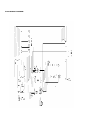
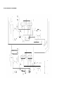
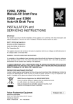
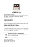
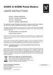
E1808, E1838, E1848
DEEP FAT FRYER
INSTALLATION, SERVICING
and USER INSTRUCTIONS
IMPORTANT
The installer must ensure that the installation of the appliance is in conformity with these instructions
and National Regulations in force at the time of installation.
Particular attention MUST be paid to BS7671 IEE Wiring Regulations
Electricity at Work Regulations
Health And Safety At Work Act
Fire Precautions Act
This appliance has been CE-marked on the basis of compliance with the Low Voltage and EMC
directives for the voltages stated on the data plate.
WARNING -THIS APPLIANCE MUST BE EARTHED
On completion of the installation these instructions should be left with the Engineer-in-Charge for
reference during servicing. Further to this, The Users Instructions should be handed over to the User,
having had a demonstration of the operation and cleaning of the appliance.
IT IS MOST IMPORTANT THAT THESE INSTRUCTIONS BE CONSULTED BEFORE INSTALLING
AND COMMISSIONING THIS APPLIANCE. FAILURE TO COMPLY WITH THE SPECIFIED
PROCEDURES MAY RESULT IN DAMAGE OR THE NEED FOR A SERVICE CALL.
PREVENTATIVE MAINTENANCE CONTRACT
In order to obtain maximum performance from this unit we would recommend that a Maintenance
Contract be arranged with SERVICELINE. Visits may then be made at agreed intervals to carry out
adjustments and repairs. A quotation will be given upon request to the SERVICELINE contact
numbers below.
WEEE Directive Registration No. WEE/DC0059TT/PRO
At end of unit life, dispose of appliance and any replacement parts in a safe manner, via
a licenced waste handler. Units are designed to be dismantled easily and recycling of all
material is encouraged whenever practicable.
Falcon Foodservice Equipment
HEAD OFFICE AND WORKS
Wallace View, Hillfoots Road, Stirling. FK9 5PY. Scotland.
SERVICELINE CONTACT
Phone: 01438 363 000
Fax: 01438 369 900
T100696 Ref. 4
IMPORTANT INFORMATION
Warranty Policy Shortlist
Warranty does not cover :• Correcting faults caused by incorrect installation of a product.
• Where an engineer cannot gain access to a site or a product.
• Repeat commission visits.
• Replacement of any parts where damage has been caused by misuse.
• Engineer waiting time will be chargeable.
• Routine maintenance and cleaning.
• Gas conversions i.e. Natural to Propane gas.
• Descaling of water products and cleaning of water sensors where softeners/ conditioners are not
fitted, or are fitted and not maintained.
• Blocked drains
• Independent steam generation systems.
• Gas, water and electrical supply external to unit.
• Light bulbs
• Re-installing vacuum in kettle jackets.
• Replacement of grill burner ceramics when damage has been clearly caused by misuse.
• Where an engineer finds no fault with a product that has been reported faulty.
• Re-setting or adjustment of thermostats when unit is operating to specification.
• Cleaning and unblocking of fryer filter systems due to customer misuse.
• Lubrication and adjustment of door catches.
• Cleaning and Maintenance
• Cleaning of burner jets
• Poor combustion caused by lack of cleaning
• Lubrication of moving parts
• Lubrication of gas cocks
• Cleaning/adjustment of pilots
• Correction of gas pressure to appliance.
• Renewing of electric cable ends.
• Replacement of fuses
• Corrosion used by chemical use of cleaners
SECTION 1 – INSTALLATION
UNLESS OTHER WISE STATED, PARTS WHICH HAVE BEEN PROTECTED BY THE
MANUFACTURER ARE NOT TO BE ADJUSTED BY THE INSTALLER
1.1 MODEL NUMBER, NETT WEIGHTS and DIMENSIONS
MODEL
E1808
E1838
E1848
WIDTH
300mm
600mm
600mm
DEPTH
850mm
850mm
850mm
HEIGHT
900mm
900mm
900mm
WEIGHT
51kg
78kg
100kG
1.2 SITING
The appliance should be installed on a firm, level floor in a well lit and draught free position.
The installation of the appliance must be made in accordance with local/or national regulations as listed
on the cover of this manual, and a competent installer must be employed.
The unit may be installed against both side and rear walls.
1.3 ELECTRICAL SUPPLY
The fryers are for use on A.C. supplies only, and the terminals are normally arranged for 2 or 3 phase
operation. Is single phase is specified it is possible to link live connections together. Cable entry is at rear
RH side of the unit, in the form of a 30mm diameter conduit connection. A conduit tube extends forward
into the control compartment. Acess to this area is gained upon removing the cover behind the door.
A suitably rated isolating switch with contact separation of at least 3mm in all poles must be installed and
the wiring executed in accordance with the relevant regulations on the front cover of this manual.
Note
When a unit is stored for a long period prior to installation, especially in damp conditions, the insulation
resistance of the elements may fall to an unacceptable level (i.e. below 2 megohm).
Should this occur, it is recommended that the elements be switched on for an hour then be allowed to
cool. This process being repeated as necessary to restore the required insulation resistance.
Warning
This appliance must be earthed.
The electrical loadings are as stated on the appliance data plate.
1.4 PRE-COMMISSIONING CHECK
Fill the pan with oil to the mark on the element guard. Approximately 19 litres (4 gallons) per pan for the
E1808 and E1848 models and 39 litres ( 8 and a half gallons) for the E1838 model. Switch on at the
isolator switch and at the fryer control panel switch. Turn the thermostat to maximum setting and check
that it operates when the oil heats up.
If possible the operator of the fryer should be made familiar with its use; the importance of never switching
on unless the elements are covered must be stressed.
SECTION 2 – MAINTENANCE
BEFORE ATTEMPTING ANY MAINTENANCE, SWITCH OFF AT THE MAIN ISOLATING SWITCH AND
TAKE STEPS TO ENSURE THAT IT IS NOT INADVERTENTLY SWITCHED ON.
2.1 ELECTRICAL CONTROL GEAR
The terminals, contactor and the thermostats are contained within a box at the front of the unit. To gain
access, open the door and remove the cover panel behind. The control panel and neon lamps are
mounted on the fascia panel, which is secured by two screws.
2.2 NEON INDICATOR LIGHTS
These must be replaced by the new lights in the event of failure. To remove a faulty light, first remove the
fascia panel. Undo the two screws through the trim, ease the panel and trim downwards then withdraw.
Pull off the terminal light connectors, and remove the light by taking off the fixing nut.
2.3 THERMOSTATS
The fryer has an electronic control thermostat and an electro-mechanical safety thermostat. Both are
mounted inside the front of the fryer but only the control thermostat is adjustable
Access is gained by removal of the control cover plate. The safety thermostat is designed to cut off the
power to the elements if the oil temperature exceeds 230°C. Manual intervention is required to re-set the
control in the event of a cut out. Re-set button is located at the bottom of the control compartment,
accessible by opining the fryer door.
2.3.1 User’s Thermostat
a) Remove the control pane.
b) Remove the control cover plate by undoing four screws on the E1808 model, and five screws on the
E1838 and E1848 models. Disconnect the electric leads to the potentiometer.
c) Undo the screws which secure the P.C.B. and withdraw.
d) Replace in reverse order.
e) To check thermostat calibration, select a temperature of 190°C on the control knob and allow the oil to
heat up. With a suitable thermometer of thermocouple immersed 25mm below the surface of the oil at
the pan centre. Check that the oil temperature corresponds with this setting.
2.3.2 Potentiometer
a) Remove the control panel.
b) Remove the control cover plate by undoing four screws on the E1808 model, and five screws on the
E1838 and E1848 models. Disconnect the potentiometer leads at the P.C.B.
c) Pull off the potentiometer knob and undo the securing screws to allow the potentiometer and bracket
to be withdrawn.
d) Undo the nut which secures the potentiometer to the bracket.
e) Replace in reverse order.
f) To check thermostat calibration, select a temperature of 190°C on the control knob and allow the oil to
heat up. With a suitable thermometer of thermocouple immersed 25mm below the surface of the oil at
the pan centre. Check that the oil temperature corresponds with this setting.
2.3.3 High Temperature Limit Device
This device is set to shut off the power to the element should the oil temperature exceed 230°C. Manual
intervention is required to reset the control in the event of a failure.
To Reset
Open the fryer door and push the button which protrudes from the underside of the control chamber.
To Replace
a)
b)
c)
d)
e)
f)
Remove the control panel.
Remove the controls cover plate.
Disconnect the electrical leads from the safety thermostat
Unscrew the nut holding the safety thermostat to the control box.
Withdraw the safety thermostat probe by undoing the nut from the boss on the fryer body. Ensure the
pan has been drained of oil. Withdraw the capillary and probe from the pan.
Replace in reverse order.
2.4 Cooling Fan
a)
b)
c)
d)
e)
Remove the control panel.
Remove the controls cover plate.
Disconnect the electric leads.
Undo the four securing nuts and remove the fan.
Replace in reverse order.
2.5 On/off switch
a)
b)
c)
d)
Remove the control panel.
Pull off the electric connections.
Push the switch out of the control panel.
Replace in reverse order.
2.6 General note
After any maintenance task, check the appliance to ensure that it performs correctly. Carry out any
adjustments necessary as in section1 – installation.
2.7 Spare Parts
When ordering spare parts, always quote the appliance type and serial number. This information will be
found on the data badge attached to the control cover behind the door.
.
E1808 WIRING DIAGRAM
E1838 WIRING DIAGRAM
E1848 WIRING DIAGRAM