1
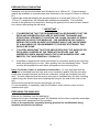
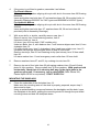
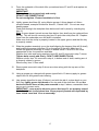
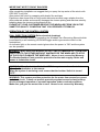
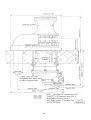
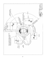
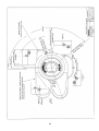
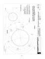
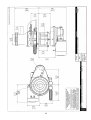
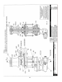
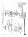
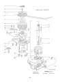
VWC, VWCLP 3500
Owners Manual
©
COPYRIGHT 1991 MAXWELL MARINE LTD
ALL RIGHTS RESERVED.
PATENTS PENDING.
PRINTED IN NEW ZEALAND.
Product Manual
Code P19073
050406
MAXWELL MARINE reserve
the right to make engineering
refinements on all products
without notice.
Illustrations and
specifications not binding as
to detail.
VWC/VWCLP 3500 OWNERS MANUAL
Page Number
CONTENTS
INTRODUCTION
SPECIFICATIONS
1
2
3-4
IMPORTANT PERSONAL SAFETY WARNINGS
APPLICATION
INSTALLATION
LOCATION - WINDLASS
- CHAIN STOPPER
- FOOTSWITCHES
- REVERSING SOLENOID
- BREAKER/ISOLATOR PANEL
- CONTROLS
CONTROL CIRCUITS
MAIN ELECTRICAL SYSTEM
HYDRAULIC SYSTEMS
PREPARATION OF MOUNTING
PREPARING THE WINDLASS
MOUNTING THE WINDLASS
OPERATION OF THE CONTROL SYSTEM
OPERATING THE WINDLASS
MAINTENANCE
SERVICING OF GEARBOX
SERVICING OF MOTOR
ORDERING SPARE PARTS AND TECHNICAL SUPPORT
5-7
8
9
9
10
10
11
11
11
12
12-13
14
15
15-16
16-18
18
19-22
23
24
24
25
INSTALLATION DRAWINGS
VWC 3500
VWCLP 3500
Deck Cutout details
WIRING DIAGRAM (DUAL DIRECTION)
WIRING DIAGRAM (SINGLE DIRECTION)
HYDRAULIC CONTROL DIAGRAM
HYDRAULIC SCHEMATIC
B203047 B203048
B203045 B203046
3338
B3424
B3555
B203101
P101820
26-27
28-29
30
31
32
33
34
P102462
35
36-37
38-39
B203099
B203100
B202039
40-41
42-43
44-45
ASSEMBLY DRAWINGS
VWC 3500 Typ. Install Drawing
VWC 3500 ACW Assembly
VWC 3500 CW Assembly
VWCLP 3500 ELECTRIC
VWCLP 3500 HYDRAULIC
GEARBOX
WARRANTY REGISTRATION
1
INSTALLATION, OPERATING INSTRUCTIONS AND SERVICE MANUAL
VWC 3500 AND VWCLP 3500 WINDLASSES
INTRODUCTION
You now own a Windlass from MAXWELL’S premier range, designed for automatic
anchor handling.
The compact deck saving vertical design allows 180º wrap of the chain ensuring
maximum engagement with the chainwheel. On VWC types a vertical drum allows
working of mooring or docking lines from any direction.
A clutch allows manual control for lowering the anchor under free fall and manual
override when using the emergency crank. The clutch also allows independent
operation of the drum on VWC types.
** IMPORTANT **
FAILURE TO ADHERE TO THE CORRECT APPLICATION, INSTALLATION,
OPERATION AND TO CARRY OUT THE MAINTENANCE SERVICE AS DESCRIBED
HEREIN, COULD JEOPARDISE YOUR SAFETY AND INVALIDATE THE
WARRANTY.
Your MAXWELL Windlass is a precision engineered product. Please read these
instructions carefully.
2
SPECIFIATIONS
PULL AT CHAINWHEEL
CHAIN SIZE
LINE SPEED AT NORMAL WORKING LOAD,HYD
LINE SPEED AT NORMAL WORKING LOAD,12VDC
LINE SPEED AT NORMAL WORKING LOAD,24VDC
POWER OPTIONS
VWC 3500
100mm (4”) Deck Clearance
200mm (8”) Deck Clearance
VWCLP 3500
100mm (4”) Deck Clearance
200mm (8”) Deck Clearance
ELECTRIC MODELS
Current at Normal Working Load
12 Volt
24 Volt
1590 kg Max (3500 lbs)
Short Link Max 14mm (9/16”)
12Metres/min (39 feet/min )
8.7Metres/min (29 feet/min )
11Metres/min (36 feet/min )
Product Code
P10086
P10088
P14076
P10096
P10098
P14085
12 Volt DC
24 Volt D.C.
Hydraulic
12 Volt DC
24 Volt DC
Hydraulic
P12091
P12093
P14091
P12096
P12098
P14095
12 Volt D.C.
24 Volt D.C.
Hydraulic
12 Volt DC
24 Volt DC
Hydraulic
130-160 Amps
66-82 Amps
Current at Stall
12 Volt
24 Volt
450 Amps
220 Amps
SUPPLY CABLES
See Pages 13-14
* HYDRAULIC MODELS
Recommended Flow
Maximum Flow
Maximum Pressure
Hydraulic Supply Lines
Hydraulic Motor Ports
Oil
40 Litre/min (11 US Gal/min)
48 Litre/min (13 US Gal/min)
138 BAR (2000 p.s.i.)
12mm (½”) diameter
7/8” UNF st’d motor (options ¾” UNF)
Viscosity ISO 32 - ISO 68 @ 20-50ºC
Suitable oils: Shell Rimula X 15W-40;
Shell Myrina M 15W-40; Penzoil SAE
10W-40; Texaco 2109 SAE 15W;
Texaco 1814 SAE 10W-40. BP
HLPHM 32-68; Castrol Hyspin AWS
T0410.
* Levels of flow/pressure below that specified can be accommodated with a motor
change - see options page 5.
Motor
Option
Max Flow/Min
Lt
US Gal
Max Pressure
Bar
P.S.I.
Max
Kg
P14367
P14366
P14365
30
25
15
138
138
138
1430 3150
1160 2550
565 1240
8.3
7.0
4.0
2000
2000
2000
3
Pull
Lbs
Normal Rate/Min
Metres
Feet
12
12
12
39
39
39
WEIGHT (Nett including Emergency Crank)
VWC 3500
Product Code
KGS
LBS
100mm (4”) Deck Clearance
P10086
P10088
P14076
P10096
P10098
P14085
48.3
48.3
40.1
49.3
49.3
41.1
106.3
106.3
88.3
108.5
108.5
90.5
P12091
P12093
P14091
P12096
P12098
P14095
43.2
43.2
35.0
44.2
44.2
36.0
95.1
95.1
77.0
97.3
97.3
79.2
200mm (8”) Deck Clearance
VWCLP 3500
100mm (4”) Deck Clearance
200mm (8”) Deck Clearance
4
IMPORTANT
PERSONAL SAFETY WARNINGS
WHEN USING YOUR WINDLASS AT ALL TIMES PRACTICE GOOD SEAMANSHIP
AND AVOID ANY LIKELIHOOD OF INJURY OR ACCIDENT BY ADHERING TO THE
FOLLOWING RULES.
AT ALL TIMES KEEP HANDS, FEET, LOOSE CLOTHING AND HAIR WELL CLEAR
OF THE WINDLASS.
NEVER USE THE WINDLASS UNDER POWER WITH THE LEVER INSERTED
EITHER IN THE CLUTCH NUT OR EMERGENCY CRANK COLLAR.
WHEN OPERATING THE CHAINWHEEL PAWL, KEEP FINGERS AWAY FROM THE
INCOMING CHAIN. OPERATE USING THE LEVER UNDER, AND GUARDED BY,
THE CHAINPIPE.
WHEN THE WINDLASS IS NOT IN USE, OR WHEN USING THE EMERGENCY
CRANK, MAKE SURE THE WINDLASS IS ISOLATED FROM THE POWER SUPPLY
BY TURNING THE WINDLASS ISOLATOR SWITCH TO “OFF”.
NEVER OPERATE THE WINDLASS FROM A REMOTE STATION WITHOUT A
CLEAR VIEW OF THE WINDLASS AND HAVING MADE SURE THAT EVERYONE IS
WELL AWAY FROM THE WINDLASS.
IF YOUR WINDLASS DOES NOT HAVE A REMOTE CONTROL STATION AND IS
OPERATED FROM THE FOOTSWITCHES ONLY, ALWAYS IMMEDIATELY AFTER
USE, TURN THE WINDLASS ISOLATOR SWITCH TO “OFF”. THIS WILL PREVENT
ACCIDENTAL WINDLASS OPERATION IF YOU OR PASSENGERS ACCIDENTALLY
STAND ON FOOTSWITCHES.
5
** IMPORTANT HINTS FOR SAFE USE OF WINDLASS **
BE SURE YOUR WINDLASS HAS BEEN CORRECTLY SPECIFIED AND
INSTALLED, YOURS AND OTHERS SAFETY MAY DEPEND ON IT. THE
WINDLASS SHOULD BE USED IN CONJUNCTION WITH A CHAINSTOPPER OF
THE APPROPRIATE SIZE. FOR AUTOMATIC OPERATION TO BE POSSIBLE, THE
ANCHOR MUST BE SELF LAUNCHING.
MAXWELL WILL NOT IN ANY WAY BE HELD RESPONSIBLE FOR SELECTION OF
A WINDLASS BY OTHERS, INCLUDING DISTRIBUTORS AND AGENTS. IF IN
DOUBT, SEND FULL DETAILS OF YOUR CRAFT TO OUR SALES DEPARTMENT
FOR APPRAISAL AND WRITTEN RECOMMENDATION.
1. Run the engine whilst raising or lowering the anchor. Not only is this a safety
precaution, it also helps minimise the drain on the batteries.
2. Always motor up to the anchor while retrieving the chain.
Do not use the Windlass to pull the boat to the anchor.
3. If the anchor is fouled, do not use the Windlass to break it out.
With the chainstopper taking the load, use the boats engine to break the anchor
loose.
4. Do not use the Windlass as a Bollard.
In all but the lightest conditions, engage the chainstopper after completing the
anchoring manoeuvre.
5. In heavy weather conditions, always use a heavy anchor snub from the chain directly
to a Bollard or Sampson Post.
6. DO NOT USE THE CHAINSTOPPER OR WINDLASS AS A MOORING POINT.
7. ALWAYS TURN THE ISOLATOR SWITCH TO “OFF” BEFORE LEAVING BOAT.
8. When using the Windlass DO NOT SWITCH IMMEDIATELY FROM ONE
DIRECTION TO THE OTHER WITHOUT WAITING FOR THE WINDLASS TO STOP
AS THIS COULD DAMAGE THE WINDLASS. Abuse is not covered by Warranty.
9. The Circuit Breaker and Isolator Switch Panel provides high current protection for the
main supply cables and also the means to isolate the circuit. When the Isolator
Switch is “ON” (red indicator light shows) the system can be activated at either the
footswitches or the remote control station. When the system is not being used,
ensure that the Isolator Switch is turned “OFF”.
10. Never proceed at speed with a bow mounted self launching anchor in position,
without first ensuring that your winch clutches are fully engaged, and having made
fast the anchor and engaged your chainstopper.
6
DO NOT DEPEND ON THE WINDLASS TO HOLD THE ANCHOR IN ITS BOW
ROLLER. A NYLON LINE SHOULD BE USED TO SECURE THE ANCHOR INTO
ITS STOWED POSITION WHEN UNDERWAY AND WILL NEED TO BE REMOVED
BEFORE OPERATION OF THE WINDLASS. ALTERNATIVELY, A PIN THROUGH
THE BOW ROLLER AND THE SHANK OF THE ANCHOR CAN BE USED FOR
SECURING.
Most Windlass models have clutches for the manual pay out of ground tackle in the
event of a loss of power. It is therefore prudent to secure the anchor to the boat by
the means described above.
7
APPLICATION
THE MAXWELL VWC AND VWCLP 3500 WINDLASSES ARE DESIGNED FOR ALL
CHAIN SYSTEMS USING UP TO A MAXIMUM CHAIN SIZE OF 14MM (9/16”)
SHORT LINK CHAIN.
To save weight, a smaller size High Tensile Chain may be used.
** WARNING **
BE SURE YOUR WINDLASS HAS BEEN CORRECTLY SPECIFIED BEFORE
INSTALLATION, YOURS AND OTHERS SAFETY MAY DEPEND ON IT.
MAXWELL WILL NOT IN ANY WAY BE HELD RESPONSIBLE FOR SELECTION OF
A WINDLASS BY OTHERS, INCLUDING DISTRIBUTORS AND AGENTS. IF IN
DOUBT, SEND FULL DETAILS OF YOUR CRAFT TO OUR SALES DEPARTMENT
FOR APPRAISAL AND WRITTEN RECOMMENDATION.
Your Windlass should have a rating of approximately 3 times total combined weight of
the anchor and chain.
The ground tackle should have been selected taking into account:
a)
Boat size, displacement and windage.
b)
Conditions of operation such as maximum depth of water, type of bottom and
weather conditions.
c)
Holding power and size of anchor, taking special note of the manufacturers’
recommendations.
CHAIN FIT
CORRECT FIT OF CHAIN TO CHAINWHEEL IS ESSENTIAL FOR THE WINDLASS
TO OPERATE PROPERLY.
A range of chainwheels are available to suit your Windlass.
The correct fit can only be guaranteed where a standard chain known to us is used.
Alternatively a 450mm (18”) or 12 links (whichever is longer) sample must be forwarded
to us to match fit. Where patterns to suit are not held by us we are able to manufacture
to instructions and reserve the right to charge cost thereof.
CHAIN STOPPER
THE WINDLASS SHOULD BE USED IN CONJUNCTION WITH A MAXWELL CHAIN
STOPPER OF THE APPROPRIATE SIZE.
8
INSTALLATION
WHERE TO LOCATE THE WINDLASS
Please refer to the installation drawings with these instructions/.
The MAXWELL VWC AND VWCLP 3500 Windlasses operate in dual direction power
UP/DOWN.
On standard installations “UP” is clockwise rotation when looking down on the
windlass. Opposite handed chain pipes are available so that handed dual Windlass
installations can be made. On the opposite hand Windlass, “UP” would correspond with
counter clockwise rotation when looking down on the Windlass.
The deckplate should be mounted pointing in the direction of the incoming chain
and with the left hand side parallel to the line of the incoming chain. This arrangement
allows the chain to have maximum engagement with the chainwheel.
The Windlass must be positioned to allow the chain to have a clear run from the
fairlead or bow roller on to the chainwheel.
The bow roller should have a vertical groove to suit the profile of the chian. This
will align the chain so that it enters the chainwheel without twisting. Ideally the
outlet from the chainpipe should be directly over the chain locker and the chain
should have at least 600mm (2ft) clear fall to allow the chain to straighten before
passing through the Windlass.
If it can be arranged the chain locker bulkhead should pass between the
chainpipe outlet in the deckplate and the Windlass gearbox. This will keep the
gearbox, motor and wiring or hydraulic hoses dry and away from flaying chain. Access
for servicing from inside the cabin area can usually be arranged through a locker.
The chain must gravity feed into the locker. If the chainpipe cannot be positioned
directly over the locker, heavy wall flexible plastic pipe can be used to direct the chain to
the required area.
It is important that the chain slips through easily, completely unaided. It may be
necessary to provide the pipe with a bell mouth or to bell mouth the entrance to the
chainpipe from the locker to assist the free flow of the chain from the locker.
The chain locker must be of such a size that the chain will heap up and feed out
naturally without fouling.
9
NOTE: Make sure you securely fasten the end of the chain to the boat.
** IMPORTANT **
FOR AUTOMATIC OPERATION TO BE POSSIBLE, THE ANCHOR MUST BE SELF
LAUNCHING. This is, once the Windlass is operated to reverse out the chain, the
anchor must free fall, or the bow roller arrangement be such that the anchor is
automatically launched.
When positioning the Windlass, make sure that there is room to swing the
emergency crank so that it will clear the pulpit and life lines or Bulwark
Allow access for conveniently connecting the supply lines under deck after the
Windlass is bolted in position.
It should be noted that the gearbox can be indexed through 4 different positions
in relation to the deckplate This can be achieved on installation by referring to the
appropriate assembly drawing and indexing at either end of the spacer tube on bolts.
Be sure to select the most convenient position and allow for the best run for the chain to
clear the motor.
WHERE TO LOCATE THE CHAIN STOPPER
The chain stopper should be positioned and aligned in a convenient position between
the Windlass and the bow roller, so that it clears the anchor stock. The chain should
pass through the stopper without being deflected.
WHERE TO LOCATE THE FOOTSWITCHES
FOOTSWITCHES SHOULD BE POSITIONED FAR ENOUGH AWAY FROM THE
WINDLASS TO ENSURE OPERATOR SAFETY.
To allow the operator to tail from the warping drum, footswitches should be at least
500mm (20”) from the Windlass.
THE BELOW DECK PORTION OF THE FOOTSWITCH SHOULD NOT BE EXPOSED
TO WATER OR WET ENVIRONMENT AND THE BREATHER HOLES MUST BE
KEPT CLEAR.
Ideally, they should be external to the chain locker. The arrows on the footswitches
should be arranged to indicate the direction of operation.
10
WHERE TO LOCATE THE REVERSING SOLENOID (Electric Windlass Only)
This unit is used ONLY when a Dual Direction control system is being installed.
(Refer wiring diagrams). The Reversing Solenoid should be located in a dry area in
close proximity to the Windlass.
IT MUST NOT BE LOCATED IN THE WET ENVIRONMENT OF THE CHAINLOCKER.
Locating close by the Windlass considerably shortens the total length of the main power
supply conductors required.
WHERE TO LOCATE THE BREAKER/ISOLATOR PANEL (Electric Windlasses Only)
The Maxwell Breaker/Isolator Panel is used when either the Dual Direction system or
the Single Direction System is used.
The Breaker/Isolator Panel is selected to provide limited protection only for the
motor and full protection for the supply cables.
This unit also provides the means for isolating the electrical system from the battery.
This should be mounted in a dry place within 1.8 metres (72”) of cable length
from battery.
This equipment or equivalent is mandatory to meet U.S.C.G. requirements.
WHERE TO LOCATE THE CONTROLS
The remote control stations can be positioned as required, i.e. Bridge, Helm, Cockpit or
Foredeck to suit your requirements.
Mount the panels where the terminals project into a dry area and if mounted in an
area where the face is exposed to the weather, i.e. Fly Bridge, the mounting must be
bedded down with sealant.
They may be wired directly to, or linked together in series to the Reversing Solenoid
(Refer wiring diagrams).
11
CONTROL CIRCUITS
MAXWELL Windlasses may be installed for single direction or dual direction
operation. The control circuits are detailed in Drawings D3555 and B3424.
These systems should be wired throughout using 1.55mm² (16 AWG) Cable. A
manually resettable ignition proof 3 amp fuse or breaker should be fitted within
one metre (40”) of the Breaker/Isolator Panel as shown on Drawing B3424.
The above requirements are mandatory for this system to meet USCG, ABYC AND
NMMA.
After all connections have been made and system tested, seal terminals against
moisture by spraying with CRC2043 “Plasti-Coat”, CRC3013 “Soft Seal” or CRC2049
“Clear Urethane”.
MAIN ELECTRICAL SYSTEM
The main electrical system is a two cable ungrounded fully insulated negative return
system.
The motor is of the isolated earth type.
This system is used to minimise electrolytic and corrosion problems.
The system should be wired as per drawing B3424 or B3555, having taken into
consideration the best location for the main elements as previously discussed.
After all connections have been made and system tested, seal terminals against
moisture by spraying with CRC2043 “Plasti-Coat”, CRC3013 “Soft Seal” or CRC2049
“Clear Urethane”.
The main supply cables should be selected from the table on the following page.
12
RECOMMENDED MAIN CABLE CONDUCTOR SIZE
12 VOLT D.C. SYSTEMS
Conductor Length
Battery to Winch
Conductor Size
Engine Room
Size Correction
____________________________________________________________________
Metres
3.1
4.6
6.2
7.7
9.2
10.8
12.3
15.4
Feet
10
15
20
25
30
35
40
50
MM²
34
34
34
42
54
54
67
85
A.W.G
2
2
2
1
0
0
00
000
MM²
42
42
42
-
A.W.G
1
1
1
-
MM²
13.3
13.3
13.3
13.3
13.3
22.0
22.0
22.0
A.W.G
6
6
6
6
6
4
4
4
MM²
22
22
22
22
22
-
A.W.G
4
4
4
4
4
-
24 VOLT D.C. SYSTEMS
Metres
3.1
4.6
6.2
7.7
9.2
10.8
12.3
15.4
Feet
10
15
20
25
30
35
40
50
NOTE
a) Conductor length means the actual length of the conductor between the battery and
Windlass.
b) Recommendations allow for a maximum 10% voltage drop approximately over the
conductor length.
c) Where portion of cable runs through the engine room a size increase should be
made as indicated.
d) Recommendations assume cable insulation has a minimum thermal rating of 90ºC.
e) The above recommendations are in accordance with the requirements of
USCG, ABYC AND NMMA.
13
HYDRAULIC SYSTEMS
Pressure/flow quoted in specification on pages 4-5 assumes operation at rated
capacity with standard motor fitted. Levels below that specified can be accommodated,
by a motor change, with a corresponding change to stall torque and/or speed. (Refer
chart page 5).
Several levels of supply and control are possible.
BASIC SYSTEM (Refer Hydrualic diagrams).
This covers applications where the Windlass is supplied from an engine driven pump or
single function power pack. Control of the Windlass is via a hydraulic bi-directional
solenoid valve which is operated by a self centering UP/DOWN toggle switch type
remote control or the footswitches.
.
14
PREPARATION OF MOUNTING
Standard units will accommodate deck thickness up to 100mm (4”). Extra clearance
models are available to accommodate deck thickness in the range of 100mm to 200mm
(8”).
It should be noted that keeping the deck thickness to no more than 75mm (3”) and
175mm (7”) respectively, will considerable enhance serviceability. This will allow
access to the gearbox mounting bolts, allowing the gearbox to be removed as a sealed
unit, without dismantling the top works.
** IMPORTANT **
1.
IT IS IMPERATIVE THAT THE DESIGNER/INSTALLER ENSURES THAT THE
DECK AND UNDERDECK PAD ARE OF SUFFICIENT THICKNESS AND
STRUCTURAL STRENGTH TO SUSTAIN THE LOADS CAPABLE OF BEING
IMPOSED ON OR BY THE WINDLASS. THE UNDERDECK PAD SHOULD
SPREAD THE LOADS AS WIDE AS POSSIBLE AND IF USE CAN BE MADE
OF A BULKHEAD OR CROSS MEMBER TO PROVIDE STIFFENING, THIS
SHOULD BE DONE.
2.
IT IS VERY IMPORTANT THAT THE ABOVE DECK PAD TOP SURFACE OR
DECK AREA COVERED BY THE TEMPLATE SUPPLIED, AND THE
UNDERDECK AREA AGAINST WHICH THE LOAD WASHERS SEAT, ARE
SMOOTH, FLAT AND GENERALLY PARALLEL.
3.
A template is supplied with these instructions for accurately spotting the mounting
holes and marking the cut outs. After spotting, bore the necessary holes. These
must be drilled parallel to each other and square to the mounting face.
Note: For boats of steel or aluminium construction, it is very important that the
deckplate is insulated from the deck with a non conductive gasket, that the mounting
studs pass through insulators and that the underdeck fixings are insulated from the
deck. It is also important that the anchor and chain is insulated from the hull, including
rubber lining, the chain locker and insulating the fixing for the end of the chain to the
hull.
Without these precautions severe electrolysis can occur.
It is not necessary to separately earth the Windlass, as the electric motor is of the
isolated earth type.
PREPARING THE WINDLASS
Remove the Windlass from the packaging.
Subject tot he type of packaging used, the Windlass will be either completely assembled
or with the motor separated from the gearbox.
Refer to the appropriate assembly drawing provided for the Windlass being
installed and proceed as follows:
15
4.
If the motor is not fitted to gearbox, assemble it as follows:
For Electric Motors
Offer motor up to gearbox aligning drive pin with slot in the worm item 20 Drawing
B202039.
Insert and tighten two bolts item 37 and washers items 38, 39 provided (refer to
Assembly Drawings B202097 for VWC types and B202099 for VWCLP types).
For Hydraulic Motors
Offer motor up to gearbox aligning drive pin with slot in the worm item 20 Drawing
202039.
Insert and tighten two bolts item 37, washers items 38, 39 and nuts item 44
provided (refer to Assembly Drawings).
5.
With a pen knife, or similar, carefully remove cap, item 1.
Remove screw, item 2 and retaining washer, item 3.
Unscrew clutch nut, item 4.
Lift drum, item 42 from shaft (VWC models only).
Undo two Bolts, item 6, with washers item 7 and remove stripper arm item 8, from
chainpipe item 13.
Lift outer clutch cone, item 5, chainwheel, item 9 and inner clutch cone, item 10
complete with springs and plungers items 46 and 45 from shaft.
Remove two keys, item 31 and retaining circlip (two halves), item 32 from shaft,
item 30.
Lift wave washer item 11 and emergency crank collar item 12 from shaft.
6.
Remove washers items 27 and 23, by undoing six nuts item 29.
7.
Remove top set of four bolts item 22 with spring washers item 23 and lift deck
plate 14 from gearbox. Remove shaft item 30 from gearbox. With gearbox held
horizontally, check that oil is showing half way up the sight glass in the
gearbox upper half. If necessary, top up with SAE90 (Shell Omala 320,
Castrol Alpha SP320 or equivalent). DON’T OVER FILL.
MOUNTING THE WINDLASS
8.
Clean the underside of the deckplate item 14.
Make sure the mounting area on the deck is properly prepared, as per step 3
above and is clean.
Using a sealant/bedding compound between the deckplate and the deck, lower
the deckplate to the deck, guiding the mounting studs 26 through the pre drilled
mounting holes and bed the deckplate down.
16
9.
From the underside of the deck offer up washers items 27 and 23 and replace six
nuts item 29.
IMPORTANT
Tighten the nuts progressively and evenly.
DO NOT USE POWER TOOLS.
Do not overtighten. Ensure installation is firm.
10. Lightly grease shaft item 30, using Marine grease, Lithium based or Lithium
complex based, example Duckhams ‘Keenol’; ‘Castrol LMX’. Do not use soap
based grease.
Feed shaft through the deckplate from below and hold in place by inserting key
item 31.
Note: If space doesn’t permit access from below, then shaft may be replaced from
the top. This will involve removing key item 33 and other circlip item 34. Replace
these from the underside once the shaft is installed.
Make sure that the circlip is properly located in the upper groove and that the key
is properly seated.
11. Slide the gearbox assembly up on the shaft aligning the keyway (this will lift shaft)
and locating the spacer tube item 35 on the spigot of the deck plate item 14.
Rotate the gearbox assembly to locate on downs Items 21 and 25 in the most
appropriate of the four positions available.
Replace four bolts and spring washers items 22 and 23 removed in step 7 above.
Tighten bolts evenly and firmly - DON’T USE POWER TOOLS.
Replace circlip item 34, removed in step 4, in bottom end of shaft, making sure it
is properly seated in groove.
Remove key item 31 from shaft.
12. Ensure parts removed in step 5 above are clean along with the top area of the
deckplate.
13. Using a grease gun charged with grease (specified in 10 above) apply to grease
nipple item 24 and grease main bearing.
14. Use grease (specified in step 10 above) and with the aid of a clean brush or nonfluffy rag, lightly grease the thread on the top end of the shaft item 30 and the
bores and clutch faces of the parts removed in step 5 above, reassemble them
as you go in reverse order.
IMPORTANT - care must be taken to ensure that keys 31 are properly seated
in shaft and that circlip halves item 32 are properly seated and captivated by
inner clutch cone item 10 on re-assembly.
17
IMPORTANT NOTE TO BOAT BUILDERS
After completing installation we suggest that you spray the top works of the winch with
CRC3097 “Long Life”
Also protect the winch by wrapping with plastic film and tape.
Experience has shown that on long ocean deliveries as deck cargo sulphur from the
ships exhausts settles and severely damages the chrome plating and stainless steel by
breaking down the chrome oxide protective film.
PLEASE LET YOUR CUSTOMER RECEIVE THE WINDLASS FROM YOU IN THE
SAME TOP QUALITY CONDITION THAT YOU RECEIVED IT FROM US.
OPERATION OF THE CONTROL SYSTEM
DUAL DIRECTION SYSTEM (Refer electrical drawings)
This system provides means of controlling the Windlass via a Reversing Solenoid which
is actuated by a self centering UP/DOWN toggle switch type remote control or the
footswitches.
An indicator light on the remote control glows when the power is “ON” and the system
can be operated.
WARNING: When using the Windlass DO NOT SWITCH IMMEDIATELY FROM ONE
DIRECTION TO THE OTHER WITHOUT WAITING FOR THE WINDLASS TO STOP
AS THIS COULD DAMAGE THE WINDLASS. Abuse is not covered by Warranty.
The Breaker/Isolator Panel provides protection for the main supply cables and
means to isolate the circuit.
WARNING: When the Isolator Switch is “ON” the system can be activated at
either the footswitches or the remote.
When the system is not being used, ensure that the Isolator Switch is turned
“OFF”.
WARNING: This system provides protection for the motor from excessive current
and short circuit. It does not provide protection against excessive heat build up
due to prolonged operation or repeated operation under overload conditions.
Make sure you give the motor time to cool. Abuse is not covered by Warranty.
18
OPERATING THE WINDLASS
LOWERING THE ANCHOR UNDER POWER
Proceed as follows:
1.
Insert the lever, item 41, into the clutch nut item 4 and check that the clutches are
tightened down firmly by turning the nut clockwise.
REMOVE THE LEVER.
2.
Check that the chain stopper is open and the pawl item 17 is disengaged from the
chainwheel.
NOTE: This may require jogging the Windlass “UP” by momentarily operating the
footswitch.
3.
If clutches are tightened down and the chain stopper and pawl are disengaged, the
Windlass may be operated under power by either using the “DOWN” footswitch or
the “DOWN” button on the Remote Control Station. Pulse the winch down to
prevent over speeding of the motor. Continue until the required amount of chain is
out.
RAISING THE ANCHOR UNDER POWER
Proceed as follows:
1.
Carry out step 1 above.
2.
If the clutches are tightened down, the Windlass may be operated under power by
either using the “UP” footswitch or the “UP” button on the Remote Control Station.
Hold until the required amount of chain has been brought in.
Care should be taken when docking the anchor. Jog in the last metre (few feet)
carefully seating the anchor home.
NOTE: It is not necessary to disengage the pawl or open the chain stopper to
operate the Windlass in the “UP” direction.
LOWERING THE ANCHOR UNDER MANUAL CONTROL
This method is generally used in tight anchorages or an emergency situation, where a
fast dump is required.
Proceed as follows:
1.
Insert the lever item 41 into the clutch nut item 4 and check that the clutches are
tightened down firmly by turning the nut clockwise.
REMOVE THE LEVER.
2.
Check that the chainstopper is open and the pawl item 17 is disengaged from the
chainwheel.
19
NOTE: This may require jogging the Windlass “UP” under power or in an
emergency by using the emergency crank lever.
IF JOGGING UNDER POWER MAKE SURE THAT THE LEVER IS REMOVED
FIRST.
3.
Standing well clear, insert the lever into the clutch nut.
Slowly back off the clutch nut.
This will release the chain.
Regulate the speed at which the chain goes out by tightening to slow, or easing to
increase.
** CAUTION **
DO NOT ALLOW THE CHAINWHEEL TO FREE WHEEL AS THIS WILL ALLOW
DANGEROUSLY HIGH CHAIN SPEEDS TO BUILD UP.
4.
When the required amount of chain is out, tighten the clutch nut firmly, remove
the lever and stow.
20
RAISING THE ANCHOR MANUALLY IN AN EMERGENCY
An emergency crank facility for raising the anchor is provided.
To use proceed as follows:
1.
Check that the chainstopper is engaged.
If a chainstopper is not fitted ensure that the pawl item 17 is engaged with the
chainwheel.
2.
Insert the lever in the clutch nut and release clutches by backing off the clutch nut
in a counter clockwise direction.
3.
Insert the ratchet lever into the emergency crank collar item 12, and engage pawl
with one of the dogs in the chainwheel in the furthermost forward position.
4.
Take the weight by pulling the lever back as far as possible, bring in the chain.
Ease off and the pawl will take the load.
Push lever to furthermost forward position and re-engage with the chainwheel.
Repeat cycle, progressively bring in the anchor.
NOTE: If a chainstopper is not fitted, or if found more convenient, the pawl item 17 may
be engaged with the chainwheel after each upward (clockwise) movement to hold the
chainwheel from reversing.
Engage pawl by using lever under the chainpipe.
USING THE WARPING DRUM (VWC Models only)
The vertical Capstan can be used independently of the chainwheel. This is ideal for
handling mooring lines, docking lines or a second anchor.
To use proceed as follows:
1.
Check that the pawl item 17 is engaged with the chainwheel.
2.
Insert the lever item 41 in the clutch nut item 4 and back off in a counter clockwise
direction until it stops.
The Capstan will now operate whilst the chainwheel remains stationery.
3.
Take several turns of line around the drum in a clockwise direction.
Whilst pulling on the tail press the “UP” footswitch. The Capstan will rotate in a
clockwise direction.
Increasing or decreasing the load on the tail, whilst holding the footswitch down
will increase/decrease the rate at which the line will be hauled in.
21
Extra turns around the drum will increase the grip and require less load on the tail.
CAUTION: ENSURE THAT FOOTSWITCH IS NOT OPERATED
ACCIDENTALLY WHILST EXTRA TURNS ARE BEING TAKEN. KEEP
FINGERS CLEAR.
DON’T PUT SO MANY TURNS ON THE DRUM THAT EASING THE LOAD ON
THE TAIL WILL NOT ALLOW THE ROPE TO SLIP ON THE DRUM.
22
MAINTENANCE
** IMPORTANT **
Failure to carry out the maintenance and service as described herein will
invalidate warranty.
Recommended Lubricants
Gearbox Oil:
SAE 90, e.g. Shell Omala 320, Castrol Alpha SP 320.
Mainshaft & Bearing:
Marine grease, lithium based or lithium complex based, e.g.
Duckhams ‘Keenol’; ‘Castrol LMX’. Do not use soap based
grease.
Above Deck
Components:
CRC 3097 Spray
1.
Prior to Season - the above deck components should be removed and greased
following the instructions under steps 5, 12, 13 and 14 of the installation
instructions.
Check level of oil in gearbox. If necessary top up as per step 7 of preparing the
windlass instructions.
The underdeck components should be sprayed, preferably with CRC3097 “Long
Life” or alternatively, CRC6-66 or WD40.
Particular attention should be paid to the motor on electric units, including the
motor terminals, footswitch terminals, terminals on the Reversing Solenoid Pack or
the Overload/Control Box plus the battery and isolator terminals.
2.
Bi-monthly throughout the Season - grease the main bearing as per step 13 of
the installation instructions.
3.
Six monthly - repeat procedure under item 1 above.
4.
End of Season - before storage carry out procedure under item 1.
5.
Above deck components - clean the Windlass with a cloth damp with Kerosene
(paraffin). Spray preferably with CRC3097 “Long Life” or alternatively, CRC6-66
or WD40. Polish off with a clean non-fluffy cloth.
Regular use of CRC3097 “Long Life” will assist maintaining the bright chrome
finish.
Natural lustre of bronze units can be restored by polishing with mild abrasive liquid
polish. Don’t use on chrome units.
23
SERVICING OF GEARBOX
The gearbox is a totally self contained sealed unit. Providing the Windlass is not
abused this unit should give years of trouble free service.
Every three years the gearbox should be removed, oil drained, cleaned and oil replaced
with SAE 90, e.g. Shell Omala 320, Castrol Alpha SP 320.
If further maintenance is required, refer to drawing B202039 and accompanying parts
list, for disassembly.
SERVICING OF MOTOR - Electric Units
If necessary, the motor can be removed from the gearbox without draining the gearbox
oil as the gearbox is a sealed unit.
The motor is removed by undoing two bolts item 37 and washers items 38 and 39 (refer
to assembly drawing B203097 for VWC types and B203099 for VWCLP types).
A replaceable drive pin item 40 is a press fit in the output end of the drive shaft. This
pin engages the slot in the worm item 20 drawing B202039.
Providing the Windlass is properly installed with the Maxwell Overload Control Box and
Breaker Panel, and the Windlass is not abused, trouble free operation can be expected.
Replacement brush sets are available - order Part No. S.P. 1383 - 12 Volt, Part No.
S.P. 1384 - 24 volt.
SERVICING OF MOTOR - Hydraulic Units
If necessary, the motor can be removed from the gearbox without draining the gearbox
oil as the gearbox is a sealed unit.
The motor is removed by undoing two bolts, item 37, washers items 38 and 39, and
nuts item 44.
(Refer assembly drawings).
24
ORDERING SPARE PARTS AND TECHNICAL SUPPORT
Please refer back cover for your nearest MAXWELL distributor
or visit our website www.maxwellmarine.com.
When ordering spare parts and for technical support, please quote the following:
Windlass Model…………………………….
Serial Number………………………………
Power Supply 12V, 24V or Hydraulic
Drawing Reference Number……………..
Item No………………………………………
Part No………………………………………
Description…………………………………
Quantity Required…………………………
25
26
27
28
29
30
31
32
33
34
35
36
37
38
39
40
VWCLP 3500 ELECTRIC
ITEM PART NO.
1
2
3
4
5
6
7
8
9
10
11
12
13/A
13/B
14
15
16
17
18
19
20
21
22
23
24
25
26/A
26/B
27
28
29
30/A
30/B
31
32
33
34
35/A
35/B
36
37
38
39
40
41
42/A
42/B
43
44
45
46
47
E3227
SP40
E3267
C3181
D3185
SP254
E3856
E1509
C3182
C3184
SP468
C3158
C3191
C3192
B1506
SP167
E3435
E2324
SP463
SP871
E3205
E3188
SP287
SP457
E2048
E3175
E3174
E3217
SP423
SP322
C3206
C3218
E3207
E2311
E3150
SP846
C3169
C3204
P12063
SP288
SP413
SP467
SP530
P20040
P10156
P10157
E3569
E3570
SP2484
DESCRIPTION
B203099
QTY
CAP
SCREW - CSK ST. ST. 3/8” x 1” LG
RETAINING WASHER
CLUTCH NUT
CLUTCH CONE - OUTER
BOLT - HEX HD M8 X 20 LG ST. ST.
LABEL
STRIPPER ARM
CHAINWHEEL
CLUTCH CONE INNER
WAVE SPRING WASHER SSR-0187-S17
EMERGENCY CRANK COLLAR
CHAINPIPE - CLOCKWISE UP - STANDARD AS SHOWN
CHAINPIPE - ANTICLOCKWISE - OPTIONAL
DECK PLATE
CAP SCREW SOC. HD. M8 X 20 LG ST.ST.
PAWL PIN
PAWL
WAVE SPRING WASHER SSR-0100-S17
SPIRAL RETAINING WASHER
PLUG
STOP PIN
BOLT - HEX HD 3/8” x 1 ¼” LG ST.ST.
WASHER - SPRING 3/8” ST.ST.
GREASE NIPPLE
DOWEL
STUD (4” TDC)
STUD (8” TDC)
WASHER
1
1
1
1
1
2
1
1
1
1
1
1
1
1
1
4
1
1
1
1
1
1
4
14
1
3
6
6
6
NUT - HEX 3/8” ST. ST.
MAINSHAFT (4” TDC)
MAINSHAFT
KEY
CLUTCH RETAINING CIRCLIP
KEY
CIRCLIP - EXT. DIAM. 1 ½” Shaft ST. ST.
SPACER TUBE (4” TDC)
SPACER TUBE (8” TDC)
GEARBOX ASSY
BOLT - HEX HD M8 x 25LG ST. ST.
WASHER - 5/16” ST. ST
WASHER - SPRING 8mm ST. ST.
ROLL PIN
EMERGENCY CRANK LEVER
MOTOR 12 V
MOTOR 24V
6
1
1
1
1
1
2
1
1
1
2
4
2
1
1
1
1
PLUNGER
SPRING
CAP SCREW
4
4
4
41
42
VWCLP 3500 HYDRAULIC
ITEM PART NO.
1
2
3
4
5
6
7
8
9
10
11
12
13/A
13/B
14
15
16
17
18
19
20
21
22
23
24
25
26/A
26/B
27
28
29
30/A
30/B
31
32
33
34
35/A
35/B
36
37
38
39
40
41
42
43*
44
45
46
47
*
DESCRIPTION
B203100
QTY
E3227
CAP
1
SP40
SCREW - CSK ST. ST. 3/8” x 1” LG
1
E3267
RETAINING WASHER
1
C3181
CLUTCH NUT
1
D3185
CLUTCH CONE - OUTER
1
SP254
BOLT - HEX HD M8 X 20 LG ST. ST.
2
E3856
LABEL
1
E1509
STRIPPER ARM
1
C3182
CHAINWHEEL
1
C3184
CLUTCH CONE INNER
1
SP468
WAVE SPRING WASHER SSR-0187-S17
1
C3158
EMERGENCY CRANK COLLAR
1
C3191
CHAINPIPE - CLOCKWISE UP - STANDARD AS SHOWN
1
C3192
CHAINPIPE - ANTICLOCKWISE - OPTIONAL
1
B1506
DECK PLATE
1
SP167
CAP SCREW SOC. HD. M8 X 20 LG ST.ST.
4
E3435
PAWL PIN
1
E2324
PAWL
1
SP463
WAVE SPRING WASHER SSR-0100-S17
1
SP871
SPIRAL RETAINING WASHER
1
E3205
PLUG
1
E3188
STOP PIN
1
SP287
BOLT - HEX HD 3/8” x 1 ¼” LG ST.ST.
4
SP457
WASHER - SPRING 3/8” ST. ST.
14
E2048
GREASE NIPPLE
1
E3175
DOWEL
3
E3174
STUD (4” TDC)
6
E3217
STUD (8” TDC)
6
SP423
WASHER
6
SP322
NUT - HEX 3/8” ST. ST.
6
C3206
MAINSHAFT (4” TDC)
1
C3218
MAINSHAFT (8” TDC)
1
E3207
KEY
1
E2311
CLUTCH RETAINING CIRCLIP
1
E3150
KEY
1
SP846
CIRCLIP - EXT. DIAM. 1 ½” Shaft ST. ST.
2
C3169
SPACER TUBE (4” TDC)
1
C3204
SPACER TUBE (8” TDC)
1
P12063
GEARBOX ASSY
1
SP279
BOLT
2
SP413
WASHER - 5/16” ST. ST
6
SP467
WASHER - SPRING 8mm ST. ST.
2
SP530
ROLL PIN
1
P20040
EMERGENCY CRANK LEVER
1
P14368
MOTOR HYDRAULIC (STANDARD MGG - 200-25)
1
SP366
NUT - HEX M8 ST. ST.
2
E3569
PLUNGER
4
E3570
SPRING
4
SP2484
CAP SCREW
OPTIONAL (SEE SPECIFICATIONS)
P14367 = MGG - 200-20
P14366 = MGG - 200-16
P14365 = MGG - 200-10
43
44
GEARBOX ASSY
ITEM PART NO.
1
2
3
4
5
6
7
8
9
10
11
12
13
14
15
16
17
18
19
20
21
22
23
24
25
26
27
28
B3135
E3168
E3146
B3134
D3225
SP650
E3141
D3226
SP644
SP722
SP172
SP726
E3170
D3137
E3288
E3287
SP838
E3145
SP643
D3140
SP642
SP844
SP721
C3136
SP159
SP720
D3263
D3223
DESCRIPTION
GEARCASE - UPPER
BUSH
BUSH
GEARCASE - LOWER
GEAR & PINION
BUSH - (FB 307) 5/18” x ¾” x 1 ½”
LAYSHAFT
FINAL DRIVE GEAR
BEARING
SEAL
SCREW - SOC. HD M6 x 20 LG
‘O’ RING
THRUST WASHER
WORMWHEEL
PINION
KEY
CIRCLIP
BUSH
BEARING
WORM
BEARING
CIRCLIP
SEAL
WORM BOX
SCREW - SOC. HD M6 x 40 LG
‘O’ RING
PLUG
SIGHTGLASS
45
B202039
QTY
1
1
1
1
1
1
1
1
1
2
7
1
1
1
1
1
2
1
1
1
1
1
1
1
4
2
1
1
46
LIMITED WARRANTY
Warranty: Maxwell Marine Ltd provides a three year limited warranty on all windlasses for pleasure boat usage, and a one year
limited warranty for those systems used on commercial or charter vessels. Warranty, service and parts are available around the
world. Contact your nearest Maxwell office for a complete list of service centres and distributors.
This warranty is subject to the following conditions and limitations:
1.
This Warranty will be null and void if
(a) there is any neglect or failure to properly maintain and service the products.
(b) the products are serviced, repaired or maintained improperly or by
unauthorised persons.
(c) loss or damage is attributed to any act, matter or omission beyond the
reasonable control of Maxwell or the purchaser.
2.
Maxwell’s liability shall be limited to repair or replacement (as determined by Maxwell) of the goods or parts defective in
materials or workmanship.
3.
Determination of the suitability of the product and the materials for the use contemplated by the buyer is the sole
responsibility of the buyer, and Maxwell shall have no responsibility in connection with such suitability.
4.
Maxwell shall not be liable for any loss, damages, harm or claim attributed to:
(a) Use of the products in applications for which the products are not intended.
(b) Corrosion, wear and tear or improper installation.
(c) Improper use of the product.
5.
This Warranty applies to the original purchaser of the products only. The benefits of the Warranty are not transferable to
subsequent purchasers.
6.
Maxwell shall not be responsible for shipping charges or installation labour associated with any warranty claims.
7.
There are no warranties of merchantability, fitness for purpose, or any other kind, express or implied, and none shall be
implied by law. If any such warranties are nonetheless implied by law for the benefit of the customer they shall be limited to
a period of three years from the original purchase by the user.
8.
Maxwell shall not be liable for consequential damages to any vessel, equipment, or other property or persons due to use or
installation of Maxwell equipment.
9.
This Warranty sets out your specific legal rights allowed by Maxwell; these may be varied by the laws of different countries.
In addition, the purchaser may also have other legal rights which vary from country to country.
10.
To make a claim under this Warranty, contact your nearest Maxwell Marine office or distributor. Proof of purchase and
authorisation from Maxwell will be required prior to any repairs being attempted.
To be eligible for warranty protection, please either complete
the form below at the time of purchase and return it to the
appropriate address above, or fill out the electronic Warranty
Form on our website, www.maxwellmarine.com
Purchaser
Name:
Telephone:
Address:
Facsimile
Supplier / Dealer
Name:
Telephone:
Address:
Facsimile
Windlass Model
Date of Purchase
Serial Number
Boat Type
Windlasses Supplied
With boat
Name
L.O.A.
Fitted by boat yard/dealer
Purchased from dealer/chandler
Built by
47
48