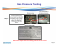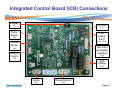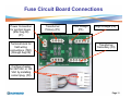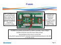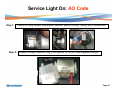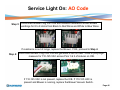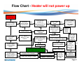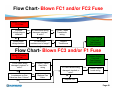
1
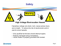
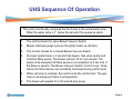
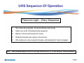
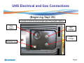
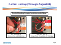
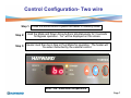
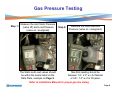
Universal H-Series
Troubleshooting Guide
© 2010 Hayward Industries
Table of Contents
Important Safety Instructions
Page 1
BD Code
Pages 30-31
Sequence of Operation
Pages 2-3
EE and CE Codes
Page 32
Electric and Gas Connections
Pages 4-5
IO and SB Codes
Page 33
Control Hookup
Pages 6-7
SF and HS Codes
Page 34
Gas Pressure Testing
Pages 8-9
HE and PF Codes
Page 35
Control Board Connections
Page 10
HF Code
Page 36
Fuse Board Connections
Page 11
LO Code
Pages 37-40
Fuses
Page 12
IF Code
Pages 41-43
Heater will not power up
Pages 13-20
AC Code
Page 44
Open FC1 and/or FC2 Fuse
Pages 21-22
AO Code
Page 45-46
Open FC3 and/or F1 Fuse
Pages 23-26
Flow Charts
Pages 47-52
Open FC4 Fuse
Pages 27-28
Wiring Schematic
Page 53
Diagnostic Codes
Page 29
Wiring Diagram
Page 54
Safety
Warning
!
High Voltage Electrocution Hazard
Hazardous voltage can shock, burn, cause serious injury
and or death. To reduce the risk of electrocution and or
electric shock hazards:
• Only qualified technicians should attempt repairs.
• Replace damaged wiring immediately.
• Insure Heater is properly grounded and bonded.
Page 1
UHS Sequence Of Operation
The control continually compares the Set Temp to the actual water temp.
When the water temp is 1° below the set point the sequence starts.
1.
The control checks for open Blower Vacuum Switch
2.
Blower starts pre-purge cycle as the igniter heats up (20 Sec).
3.
The Control checks for a closed Blower Vacuum Switch.
4.
At proper Igniter temp a 4 second trial begins. Gas valve opens and
monitors flame sense. The blower will turn off for one second. The
Igniter is de-energized at flame sense or at completion of 4 sec trial. If
the flame is sensed, The Blower Vacuum Switch, Control Loop, Temp
Sensor & Flame Sensor are constantly monitored during call for heat.
5.
When set temp is reached, the control ends the call for heat. The gas
valve is de-energized, flame is extinguished.
6.
The blower will operate for a 30 second post purge.
Page 2
UHS Sequence Of Operation
Failure to Light – Retry Sequence
1.
Gas Valve de-energizes, 30 second blower post purge.
2.
Starts over at #2 of heating mode sequence.
3.
Retries 3 times until lockout (IF Code)
4.
Waits 60 minutes then retries 3 more times
5.
Will continue to retry every 60 minutes, until demand for heat is stopped.
Note: When making keypad entries of any type there may be a 5-10 sec delay for certain situations.
Page 3
UHS Electrical and Gas Connections
(Beginning Sept 08)
Located on both the left and right side of the heater cabinet.
Gas
Supply
High
Voltage
Low
Voltage
Bonding Lug
Page 4
Electrical & Control Connections
(Beginning Sept 08)
120 VAC or 240
VAC Connection
Three Wire
Remote
Connection:
Orange (Pool),
White (24V), and
Red (Spa).
Ground
Two Wire Remote
Connection: Orange
(Pool) and White
(Common)
Page 5
Control Hookup (Through August 08)
Control hookup located outside control box.
Two Wire Hook up:
Orange (Pool) and White (24v)
Three Wire Hook up:
Orange (Pool), White (24v), and Red (Spa)
Page 6
Control Configuration- Two wire
Step 1: Press the Mode button to place the heater in Standby Mode.
Step 2:
Hold the Mode and Down Arrow buttons simultaneously for 3 seconds
for Bypass operation. “bo” will be displayed on the screen.
Step 3:
Heater must then be in Spa or Pool Mode for operation. The heater will
fire when instructed by the external control.
Note: 104° maximum temperature.
Page 7
Gas Pressure Testing
Measure the inlet Static Pressure
Step 1:
(valve off) and Load Pressure
(valve on / energized).
The Static and Load values should
be within the levels listed on the
Data Plate, example on Page 9.
Step 2:
Measure the outlet Manifold
Pressure (valve on / energized).
Manifold reading should be
between 1.8”- 2.0” w.c for Natural
or 6.8”- 7.0” w.c for Propane.
Refer to Installation Manual for proper gas line sizing.
Page 8
Gas Pressure Testing
Remove plug
Step 3:
Turn clockwise to
increase pressure.
If inlet pressures are
correct and the Manifold
Pressure is low or high,
adjust the Manifold
Pressure at the Gas
Valve.
Heater Data Plate
Note: Never adjust valve if incoming pressure is not correct.
Page 9
Integrated Control Board (ICB) Connections
Display
3A Fuse
(E7)
(F1)
Temp.
Sensor
Low
Voltage
R&C
(E2)
(E12 , E13)
Flame
Sensor
Gas Valve
and Safety
Switches
(E4)
Remote
Control
(E11)
(E1)
High
Voltage
(E10)
Igniter
Blower/Inducer
(E3)
(E6)
Page 10
Fuse Circuit Board Connections
Power Connection
for junction boxes.
(after Aug 08)
(P1)
Terminal block for
field wiring
connections. (TB1)
(through Aug 08)
Transformer
Primary (P3)
Low Voltage
(P5)
High Voltage (P6)
Transformer
Secondary (P4)
3a
3a
Configure heater
for 240 VAC or 120
VAC by installing
correct plug. (P2)
Page 11
Fuses
FC1 and FC2 fuses
protect the primary
input voltage. These
fuses blow due to a
shorted Fuse Board,
shorted Transformer,
improper or
excessive voltage.
3A
3A
The FC4 fuse
protects the
transformer
(120VAC
secondary output
voltage) from a
failed Blower,
Igniter, or ICB.
The FC3 fuse protects the transformer 24VAC secondary output voltage.
Situations that will cause this fuse to blow include:
•Short between FC3 to R & C on the ICB.
• Any short to ground at the E1 connector (external remote terminal) on the ICB
or 24 VAC circuit.
Page 12
Troubleshooting: Heater will not power up
Step 1:
Verify incoming voltage to heater is present (110-125 or 220-245 VAC), if
voltage is present, proceed to Step 2. Otherwise, correct incoming line
power to heater.
Models Prior to August 2008
Models After August 2008
Page 13
Troubleshooting: Heater will not power up
Step 2: Verify Voltage Selector Plug matches incoming line power.
Step 3: Inspect Fuse Board wiring and ensure all plugs are securely fastened to board.
Page 14
Troubleshooting: Heater will not power up
Step 4:
Verify that FC1 and FC2 Fuses are not open. Check incoming voltage at bottom
of both fuses (Fig. A) and out going voltage at top of both fuses (Fig. B), if no
voltage present at top of both fuses, remove fuses from the Fuse Holders and
measure continuity across each Fuse (Fig. C).
Fig. A
Fig. B
Continuity
Fig. C
If Fuses are open, proceed to Page 22. Otherwise, reinstall the Fuses and continue to Step 5.
Page 15
Troubleshooting: Heater will not power up
Step 5: Disconnect plug from P4 connector from Fuse Board. Measure for 22-28 VAC
between pins 1 & 2 of plug from Transformer and 110-125 VAC between pins 4 & 6.
If either voltage is incorrect, proceed to Page 22. Otherwise, proceed to Step 6.
Page 16
Troubleshooting: Heater will not power up
Disconnect plug from P5 connector on Fuse Board and measure for low voltage (22-28
Step 6: VAC) between R & C pins of P5 receptacle on Fuse Board. If voltage is not present,
proceed to Step 7. Otherwise, proceed to Step 8.
Measure for low voltage (22-28 VAC) between P5 C pin and bottom of FC3 fuse. If
Step 7: voltage is not present, replace Fuse Board. Otherwise, measure for low voltage
between P5 C pin and top of FC3 fuse. If voltage is not present check for blown fuse.
If fuse is blown proceed to Page 12, if voltage is present proceed to Step 8.
Page 17
Troubleshooting: Heater will not power up
Step 8: Inspect ICB wiring and ensure all plugs are securely fastened.
If wiring is OK and plugs are securely fastened, proceed to Step 9.
Page 18
Troubleshooting: Heater will not power up
Step 9:
Verify low voltage (22-28 VAC) to ICB between R & C terminals.
If voltage is incorrect, replace the Wire Harness. If voltage is correct, proceed to Step 10.
Page 19
Troubleshooting: Heater will not power up
Step 10:
Verify that F1 Fuse (3 AMP) on ICB is not open by measuring continuity across
the Fuse. If fuse OK, proceed to Step 11. If fuse is blown, proceed to page 24.
Verify 22 – 28 VAC is present between COM and AC terminals on ICB board. If
Step 11: voltage is present and display is blank, replace Display Board. If voltage is not
present, replace ICB.
Page 20
Troubleshooting: Open FC1 and/or FC2 Fuses
Step 1:
Verify that 120 VAC Voltage Selector Plug is NOT installed with a 240
VAC field power supply.
If correct plug is installed, proceed to Step 2. If incorrect, turn the power off and
install the 240 VAC plug. Then replace FC1 and FC2 Fuses.
Page 21
Troubleshooting: Open FC1 and/or FC2 Fuses
Step 2:
Check for faulty Transformer
wiring and ensure the insulation
on the wiring is not worn.
Remove P4 and P3 plugs. Measure
Transformer for resistance of
Step 3:
1.9 - 2.9 ohms between Black to
Brown wires and between Orange
to Yellow wires of P3.
If resistance is out of range, replace the Transformer.
Page 22
Troubleshooting: Open FC3 and/or F1 Fuse
Step 1: Check low voltage wiring / connections for worn insulation or pinched wiring.
Page 23
Troubleshooting: Open FC3 and/or F1 Fuses
Step 2:
Inspect Gas Valve wiring and ensure insulation is not worn.
If wiring is OK, proceed to Step 3.
Page 24
Troubleshooting: Open FC3 and/or F1 Fuses
Step 3:
Measure resistance across Gas Valve terminals (greater than .5 ohms)
and between each terminal to Ground for short (there should be no
continuity between either terminal to ground).
If a short exists (less than .5 ohms), replace the Gas Valve.
Otherwise, proceed to Step 4.
Page 25
Troubleshooting: Open FC3 and/or F1 Fuses
Step 4: Check for faulty ICB wiring and ensure insulation on wiring is not worn.
If wiring is OK, replace the ICB.
Page 26
Troubleshooting: Open FC4 Fuse
Step 1:
Inspect the Igniter and Blower Wiring and ensure the insulation is not worn.
If wiring is OK, proceed to Step 2. Otherwise, replace the defective component(s).
Page 27
Troubleshooting: Open FC4 Fuse
Step 2:
Disconnect the Igniter Plug from the ICB and measure resistance across the
Igniter. Resistance should be 10.9 – 19.7 ohms @ 77 degrees.
If resistance is out of range, replace the Igniter. If OK, proceed to Step 3.
Step 3:
Disconnect the Blower Plug from ICB and measure the Blower resistance. Resistance
should be 8-9 ohms from Black to Red wires and White to Blue wires.
If resistance is out of range, replace the Blower. Otherwise, proceed to Page 30.
Page 28
Diagnostic Codes
Below is a list of all Diagnostic Codes for the UHS Heater.
Troubleshooting Steps for each Code are covered on the following pages.
Diagnostic Code
Description
AC
Blower Vacuum Switch closed
AO
Blower Vacuum Switch open
BD
Bad board or secondary high voltage fault
CE
Communication Error Between Control Module and Display Interface Assembly
EE
Bad board
HE
Rapid water temperature rise
HF
Flame present with Gas Valve not energized.
HS
Maximum return water temperature exceeded.
IF
Ignition Failure
IO
Igniter Failure
LO
Water Pressure Switch, Vent Pressure Switch, or Temperature Limit Switch Fault
PF
Voltage polarity reversed, low voltage detected
SB
Keypad failure
SF
Temperature Sensor (thermistor) input failure
Page 29
Service Light On: BD Code
Step 1:
BD Code: Bad Board or Secondary High Voltage Fault. Remove
FC4 Fuse and measure continuity.
If Fuse is blown, go to Page 27 (Open FC4 Fuse). If OK, proceed to Step 2.
Step 2:
Disconnect plug from P6 connector of Fuse Board and measure for
110-125 VAC across Pins 3 and 5 of P6 receptacle on Fuse Board.
If OK, proceed to Step 3. Otherwise, go to Step 4.
Page 30
Service Light On: BD Code
Step 3:
Disconnect plug from E10 connector of ICB and measure for 110 -125 VAC
across pins 1 and 3 of plug on Wire Harness.
If 110-125 VAC is present, replace the ICB. Otherwise, replace the Wire Harness.
Step 4:
Disconnect plug from P4 connector of Fuse Board and measure for 110 -125
VAC between pins 4 and 6 of plug from Transformer.
If 110-125 VAC is present, replace the Fuse Board. Otherwise, replace the Transformer.
Page 31
Service Light On: EE and CE Codes
EE Code: “EEPROM Error” Defective ICB board. Replace ICB.
CE Code:
“Communication Error” between ICB and display board. Error may be
cleared by cycling line power off and on. Otherwise, inspect Display
Interface ribbon cable and ensure plug is securely attached to ICB.
Front
Back
ICB
Display
Board
If Display Interface ribbon cable and connector plug is OK, replace the
Display Interface Assembly. If code is still present, replace the ICB.
Page 32
Service Light On: IO and SB Codes
IO Code: “Igniter Open” Inspect Igniter wiring, ensure Igniter plug is securely
attached to the ICB. Verify Igniter ohm resistance (10.9-19.7 Ohms).
If wiring damaged and/or ohms resistance is out of range, replace the Igniter.
SB Code: “Stuck Button” requires the Bezel/Keypad assembly to be replaced.
Page 33
Service Light On: SF and HS Codes
Step 1: SF Code: “Sensor Failure” Inspect Temperature Sensor (thermistor) wire, make
sure sensor is plugged into ICB securely.
Measure resistance between black wire and each red wire, the Temperature
Step 2: Sensor resistance should be the same (10k ohms at 77 degrees). If readings are
significantly different from each other, replace the temperature sensor. Otherwise
replace the ICB.
HS Code: “High Temperature Sense” If water temperature exceeds 105°F the heater will
shut down and go into lockout. Automatic restart is 2 minutes after water temp
drops below 105°F.
Page 34
Service Light On: HE and PF Codes
HE Code:
“Heat Rise Excessive” Inlet water temperature exceeds 5°F in a 5
second period. This is interpreted as a superheated water condition. If
the control detects this condition 3 times, it will lock out and will require
a power-cycle to reset.
“Polarity Failure” This code will display if 120V polarity is reversed, low
PF Code:
voltage is detected, or if the ground path is not sufficient. Reset is
immediate after error is corrected.
Page 35
Service Light On: HF Code
HF Code:
“Heat or Flame Sensed” Heat sensed when gas valve should be “OFF”. If flame is
sensed with the gas valve off, the control will go into lockout. The blower will
continuously run until error condition is corrected. When corrected, control will run
blower for 5 seconds then automatically restart heater after 2 minutes.
Reset heater, cycle line power off and on.
If the code is still present, the Gas Valve is defective and needs to be replaced.
Page 36
Service Light On: LO Code
Step 1:
LO Code: “Limit Open” Verify pump is running and adequate water is
flowing through heater. LO Code is normal when the pump is turned off.
Step 2:
Inspect Water Pressure Switch wiring and ensure Wire Harness terminals are
securely fastened to the spade terminals on the Water Pressure Switch.
Remove wires from Water Pressure Switch and measure continuity across the
Step 3: terminals while pump is running. If open, replace Pressure Switch. Otherwise, go
to Step 4.
Page 37
Service Light On: LO Code
Step 4:
Certain applications will require the adjustment of the Pressure Switch, refer to
section of the installation/service manual Water Pressure Switch Test /
Adjustment Procedures.
Step 5:
Inspect Temperature Limit Switch Wiring and ensure wire
harness terminals are securely fastened.
Page 38
Service Light On: LO Code
Step 6: Measure continuity across the Temperature Limit Switches.
If open, replace the Temperature Limit Switch(s).
Applies Only To Indoor Installations
Step 7: Inspect the Vent Pressure Switch Wiring and Hose connections. Ensure Wire Harness
is securely fastened and tubing is attached to Blower and Vent Pressure Switch.
If OK, proceed to Step 8.
Page 39
Service Light On: LO Code
Applies Only To Indoor Installations
Step 7: Ensure that flue is not blocked or restricted. See indoor vent sizing requirements
in Installation Manual.
Step 8:
Remove wires from Vent Pressure Switch and measure continuity between
terminals. While heater is running, measure continuity across the Vent Pressure
Switch.
If open, replace Vent Pressure Switch.
Page 40
Service Light On: IF Code
Step 1:
IF “Ignition Failure” Ensure main gas shutoff outside the heater is open and that
the Gas Valve inside the heater is in the “ON” position.
Step 2: Inspect Flame Sensor and Gas Valve wiring and ensure wire harness is securely
fastened to the terminals.
Step 3: Ensure Gas Static, Load and Manifold pressures are correct. See Page 8.
If OK, proceed to Step 5, Otherwise proceed to Step 4
Page 41
Service Light On: IF Code
Step 4: Measure for 22-28 VAC across Gas Valve during trial for ignition.
If 22-28 VAC is present and Gas Valve does not open with manometer connected
to valve, replace Gas Valve. See Page 8 for reference. If 22-28 VAC is not
present, replace the ICB.
Step 5:
For models manufactured prior to 4/14/2009
Verify which flame sensor is installed. If 3" flame sensor installed, replace to
5" flame sensor. Part # IDXLFLS1930
Page 42
Service Light On: IF Code
Step 6: Remove and inspect Gas Orifices and Burners for blockage.
NOTE: Check for excessive moisture in combustion chamber.
Determine possible causes; roof run-off, sprinklers, etc..
Page 43
Service Light On: AC Code
Step 1:
AC Code: “Air Switch Closed” Blower vacuum switch closed when
expected open. Disconnect wires and tubing from switch, measure continuity
between terminals on switch, if continuity exist, replace switch.
Step 2: With heater off, If blower continues to run, replace ICB.
Page 44
Service Light On: AO Code
Step 1:
Step 2:
Check for faulty Blower and Blower Vacuum Switch Wiring, Tubing, and Connections.
Ensure Voltage Selector Plug is configured for correct field supplied voltage.
Page 45
Service Light On: AO Code
Step 3: Disconnect Blower Plug from ICB and measure resistance across Blower
windings for 8 to 9 ohms from Black to Red Wires and White to Blue Wires.
If resistance is out of range, replace the Blower. If OK, proceed to Step 4.
Step 4: Disconnect Blower Plug from ICB and generate a call for heat. While in pre-purge,
measure for 110-125 VAC across Pins 1 & 2 of inducer on ICB.
If 110-125 VAC is not present, replace the ICB. If 110-125 VAC is
present and Blower is running, replace the Blower Vacuum Switch.
Page 46
Flow Chart - Heater will not power up
Heater will not
power up
Is 22-28 VAC
present on P5?
Yes
No
Is all ICB
wiring secure
and correct?
Yes
Is 22-28 VAC
present on
terminals R & C of
Control Board?
No
Yes
Go to “Blown FC3
and/or F1 fuse”
section.
No
Is field supply
voltage present
on P1?
Replace Wire
Harness
Yes
Replace ICB.
Is all Fuse Board
wiring secure and
correct?
Yes
Is FC1 or FC2 Fuses Open?
No
Correct wiring.
Problem Solved. If not, call
Tech Support (908) 355-7995
Replace Wire Harness
Correct field wiring to heater.
Replace Fuse Board.
Replace Transformer.
Yes
Go to “Open
FC1 and/or
FC2 fuse”
section
(Page 21)
No
Is proper Voltage
Selector installed?
No
No
Replace
Display
Board
No
Yes
Is field supply
voltage present in
junction box?
Yes
(Page 23)
Is 22-28 VAC
present on pins
1&4 of E7?
Yes
No
Go to “Open
FC3 and/or F1
fuse” section
No
No
Correct wiring.
Is FC3 Fuse
blown?
Yes
Is F1 Fuse
Open?
Install correct plug.
Yes
No
Is 110125 VAC
present at
P4?
Yes
Is 22-28
VAC
present on
pins 1&2 of
P4?
Yes
No
Replace
Transformer.
Page 47
Flow Chart- Blown FC1 and/or FC2 Fuse
Blown FC1 and/or
FC2 Fuse
Is proper
voltage selector
installed?
Yes
Is Transformer wiring
damaged, pinched,
or worn?
No
Install proper
voltage selector.
Yes
Correct / repair
Transformer
wiring
Problem Solved.
If not, call
Tech Support
(908) 355-7995
No
Is Transformer
resistance out of range?
Yes
Replace
Transformer
No
Flow Chart- Blown FC3 and/or F1 Fuse
Blown FC3 and/or
F1 Fuse
Is Gas Valve wiring
damaged, pinched, or
worn?
Yes
Correct / repair
Gas Valve
wiring
No
Is resistance on Gas
Valve less than .5 ohms?
No
Yes
Replace Gas
Valve.
Problem Solved.
If not, call
Tech Support
(908) 355-7995
Is Control Board wiring
damaged, pinched, or
worn?
Yes
Correct / repair
board wiring.
No
Replace ICB.
Page 48
Flow Chart- BD Code
BD Code
Is the FC4
Fuse open?
Go to “Open
FC4 Fuse”
Section
Yes
(Page 27)
No
Is 110-125 VAC
present on pins 3 & 5
of P6 receptacle?
Yes
Is 110-125 VAC
present on pins 1 & 3
of E10 Plug? (Page 31)
Yes
Replace the ICB.
(Page 30)
No
No
Replace the
Wire Harness.
Replace the
Transformer.
No
Is 110-125 VAC
present on pins 4 & 6
of P4 Plug? (Page 31)
Yes
Replace the
Fuse Board.
Problem Solved. If not,
call Tech Support
(908) 355-7995
Page 49
Flow Chart- LO Code
LO Code
Is the pump
running?
Yes
Is water flow
above
minimum
required?
Yes
Is the Water
Pressure
Switch
closed?
Yes
(Page 37)
No
Turn the
circulation
pump on.
No
Backwash or
clean the filter.
No
Adjust Water Pressure
Switch if needed. refer
to the pressure switch
adjustment section of
the installation /
service manual. LO
Code Cleared?
Indoor Installations
Only
Is the Vent
Pressure Switch
closed? (Page 39)
No
Is the flue blocked
or restricted?
Yes
Are the High
Limit Switches
closed? (Page 38)
No
Replace the
High Limit
Switches
No
No
Replace the
Water
Pressure
Switch
Replace the
Vent Pressure
Switch
Problem Solved. If not,
call Tech Support
(908) 355-7995
Page 50
Flow Chart - IF Code
IF Code
Gas supply
shutoff valves
and Gas Valve
turned on?
No
Yes
Is inlet gas
supply pressure
between min.
and max.? (Page 8)
No
Yes
Is the Flame
Sensor plugged
in and 5” in
length? (Page 42)
Yes
No
During 4 sec trial for
ignition, is 22-28 VAC
present at Gas Valve
and 110-125 VAC at
Igniter? (Page 42)
Yes
No
Turn on Gas
valves.
Adjust the gas
pressure
(Page 8)
Plug in or replace
the Flame
Sensor.
Inspect Orifices
and Burner
Tubes (Page 43)
Replace the ICB.
Yes
Is the Manifold
gas pressure
correct? (Page 8)
No
Problem Solved. If not,
call Tech Support
(908) 355-7995
Inspect Combustion
Chamber for
moisture
Adjust Manifold
gas pressure.
(Page 43)
(Page 9)
Page 51
Flow Chart - AO & AC Code
AO Code
Is the Blower
Vacuum tubing
and wiring.
OK? (Page 45)
No
Replace
damaged parts.
Yes
Is the correct
Voltage Selector
Plug installed?
Yes
(Page 45)
Is the Blower
resistance
within range?
Yes
(Page 46)
No
No
Install correct
plug.
Replace the
Blower.
Is 110-125
VAC present
at Blower
relay? (Page 46)
Yes
Replace the
Blower
Vacuum
Switch.
No
Replace the
ICB.
Problem Solved. If not,
call Tech Support
(908) 355-7995
AC Code
Is the Blower
relay open?
(Page 44)
Yes
Replace the Blower
Vacuum Switch.
No
Replace the
ICB.
Problem Solved. If not,
call Tech Support
(908) 355-7995
Page 52
L / L1
240v
plug
N / L2
Schematic
120v
plug
P1/2
P1/1
P2 / T4
P2 / T2
P2 / T3
P2 / T1
FWP
FWP
FC2 Fuse
FC1 Fuse
circuit # 3
circuit # 1
P3 / T3
P3 / T4
120v
P4 / C
P4 / 24v
circuit # 2
FC3 Fuse
E12 / R
E10 / H
P4 / N
circuit # 4
FC4 Fuse
FWP
Relay
P6 / N
ICB
E10 / N
E3 L Igniter
E3 R
E6 R Blower
E6 W
F1 / 3 Amp Fuse
Relay
Display Board
120v
P6 / H
Note:
Integrated
Control Board
COM
24 VAC
P4 / 120v
P5 / R
E11/6
E11/5
E11/4
E11/3
E11/1
E11/2
E7
AC
(opt) VPS n/c
BVS n/o
WPS n/o
Relay
Hi Limit n/c
ICB
Hi Limit n/c
E13 / C
Gas Valve
FWP
120v
Isolation
Transformer
24v
P5 / C
P3 / T1
P3 / T2
Temp Sensor - (ohms)Ω
between black and each
red should read the same.
77°F = 10,000 Ω
1.
The Igniter, Blower and Gas Valve
relays are an integral part of the ICB
(Integrated Control Board)
2.
Wiring internal to the ICB and temp
sensor are indicated by a dotted line,
i.e. ……………..
3.
Isolation transformer creates 4 circuits
as shown for troubleshooting.
Bezel Ribbon Cable Continuity
1 & 4 Mode Switch
1 & 3 Temp Set Red (up)
1 & 2 Temp Set Blue (down)
Top
4
3
2
1
Page 53
Wiring Connection Diagram
Page 54