1
Donated by John & Susan Hansen - For Personal Use Only
L-UNE MOTOR TRUCK SERVICE MANUAL
CLUTCHES
Specifications
and Index
Page 1
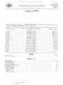
CLUTCH GROUP Motor truck models and their corresponding clutch models are shown in the following list. Clutch
model specifications will be found on specification page 2.
TRUCK MODEL
CLUTCH MODEL
RK-IOB
L-IIO. . ..
. .......... . RK-IOB
L-120. . . .
. .......... . RK-IOB
LM-120 . . .
. ......... . RK-IOB
L-130 . . . . . . . . . . . . . . . . . . . . LB-140 . . . . . . . . . . . . . . . . . . . RK-IOB
L-150 . . . . . . . . . . . . . . . . . . . . RK-IOB
L-153. .
. ......... . LM-150
.......... . RK-IOB
R-IIA-l
L-160. .
. ....... . R-IIA-l
L-163. . . . .
. ...•.... L-164 . . . . . . . . . . . . . . . R-IIA-l
R-IIA-l
L-165 . . . . . . . . . . . . . . . . . . . . LC-160 . . . . . . . . . . . . . . • . . . . R-IIA-l
L-170. .
. . . . . . . . • . • . . . R-l1A-1
L-l 73 . . • . . . • . . . . . . . . . . . . . R-IIA-l
L-174. . . . . . . . . . . . .
. . . . • R-IIA-l
L-l 75 . . . • . • . . . . . . . . . . . . . . R-IIA-l
R-IIA-l
LF -170. . . .
. ........ . L-IBO. .
. . . . . RK-IIA-l
L-IB3. . . . .
. . . . . . . . . . RK-IIA-l
TRUCK MODEL
CLUTCH MODEL
L-184 . . . . . . . . . . . . . . . . . . . . RK-IIA-l
L-IB5 . . . . . . .
. . . . . RK-IIA-I
LC-IBO . . . . . . . . . . . . . . • . . . . RK-12-1Z
RK-IZ-15
L-190 . . . . . . . . . . . . . . . . . . RK-IZ-15
L-193 . . . . . . . . . . . . . . . . . . . RK-12-15
L-194 . . . . . . . . . . . • . . . . . . R-14-15
L-195 . .
. ......... . LC-190 . . . . . . . . . . . . . . . . R-14-15
LF-190 . . . . . . . . . . . . . . . • . R-14-15
L-200 . . . . . • . . . . . . . . . . . . . R-14-15
L-204 . . . . . . . . . . . . . . . . . . . . R-14-15
L-205 . . . . . . . . . . , . . . . . . . . LC-200 . . . . . . . . . . . . . . . . . . . R-14-15
L-210 . . . . . . . . . . . . . . . . . . . . LF-210 . . . . . . . . • . . . . • . . . . . R-14-15
R-15-B
L-220 . . . . . . . . . . . . . . . . . . . . R-15-B
L-ZZ5 . . . . . . . . . . . . . . . . . . . . LF-220 . . . . . . . . . . . . . . . . . . . L-Z30 . . . . . . . . . .
. .•.. LF-230 . . . . . . . . . . . . . . . . . . . INDEX SPECIFICA TIONS . . . . . . . . . . , . . . Page
Z
SECTION "An
A.djustments . . . . A.ssembling clutch :::;lutch chatter . . . :::;lutch description . . . . . . . . . . . . .
Jriven member assembly . . . . . . . .
:nstalling clutch . . . . . . . . )verhaul fixture. . . . . .
. .....
::ledal adjustment . . . . . . . . . . . . . .
'Zelease levers . . . . . . . . . . . . . . . .
'Zemoval . . . . . . iervicing clutch . . . . PRINTED IN UNITED STATES OF AMERICA
1 To 3
7
9
.
.
.
.
.
4
4
B
5
9
7
4
5, 6
Donated by John & Susan Hansen - For Personal Use Only
'1jPlUl()
Pl ~ 't:l .....
OQP- (\\ l
(\\H
OC
N~~~
g- o· ()
>(Pl::r::
::tM
§Ul
[/l
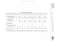
CLUTCH SPECIFICATIONS
-_ _----
-
CL UTCH MODELS (IH)
- -
RK-IOB
---
.............
--------------
R-llA-1
RK-12-12
r
RK-12-15
-----
R-14-15 R-15-8 t
z
tTl
Clutch Model (Manufacturer). .
Number of plates . . . • . .
Vibration dampener . . . .
10-TT
1
Coil Spring
Il-TT
1
Coil Spring
Pressure Springs;
Number used . • . . . . . . .
Pounds pressure . • . . . .
at. • . . . . . . • . . . . .
9
145
1-7/16 11
12
145
1-7/16 11
12-TT
12-TT
1
1
Coil Spring Coil Spring
12
145
1-7/16 11
15
145
1-7/16 11
14-TT 1
Coil Spring 15-TT 1
Coil Spring 15 175 1-13/16 11 18 175 1-13/16 11 3:
o-l
o~
-l
~
C
n
7\
Clutch Facings:
Number used . . . . . . . . .
2
2
2
2
2
(f)
2
tTl
~
<
Release Lever Adjustment:
Flywheel surface to
levers . . . . . . . . • . .
1-13/16 11
2"
Clutch Pedal Free Travel. . . .
1 to 1-1/2 11
1 to 1-1/2 11
2-1/8 11
2-1/8 11
1 to 1-1/2 11 1 to 1-1/211
Capscrew size for
removal and installation . 3/8-16xl-3/4 11 3/8-16xl-3/4 11 3/8-16x2 11
-
n
2-5/8 11 1 to 1-1/2" 2-3/4 11 1 to 1-1/2 11
3/8-16x2 11 3/8-16x2-1/4 11 3/8-16x2-1/2"
------------
tTl
3:
»z c
»
r
Donated by John & Susan Hansen - For Personal Use Only
R-LINE MOTOR TRUCK SERVICE
CLUTCH
Section A
Page 1
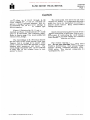
CLUTCH
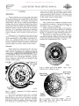
Clutches on the R-110 through R-190
series chassis (1011, II" and 12" clutches) use
a new cushion type driven member. this re
quires a change in release lever settings to
accommodate the new thicker cushion type
driven member.
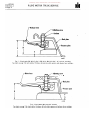
Figure 1 illustrates the 10. 11 and 12 inch
clutches and Figure 2 illustrates the 14" clutch
used in R-line trucks (see following page).
Refer to chart on page 3 for truck models and
release lever settings.
The clutch linkage on R-lSO and up chassis
has two holes in the clutch release lever (see
Figures 3 and 4 on page 4) to assure clean
clutch release and afford the operator a choice
between pedal pressures and travel.
The
clutch linkage adjustable yoke can be installed
in either hole on the release lever to suit
operator's choice.
CTS 12-MARCH 1953 (Supplemental pages (or CTS·)l).
The clutch pedal free travel for all R-line
chassis is 2 inches. It is important that clutch
pedal free travel be maintained to avoid pre
mature clutch failure. Keep clutch control
linkage lubricated.
Clutch release bearing sleeves on all R-line
chassis incorporate a lubricator fitting to pro
vide means of lubricating the clutch release
bearing. sleeve and fork without their removal
from chassis. Lubricate as follows:
Fill release bearing sleeve using hand
gun. Do not over-lubricate. Lubricate every
15,000 to 20,000 miles. Under unusual "Stop
and-Go" driving conditions lubricate every
10,000 miles.
Use lubricant comparable to
"Lubriplate No. 110."
PRINTEO IN UNITED STATES OF' AMERiCA.
Donated by John & Susan Hansen - For Personal Use Only
CLUTCH
II
III
R-L1NE MOTOR TRUCK SERVICE
Section A
Page 2
-Release lever
Adjutinr screw
C
B
A..J051T
Fig. 1· Clutch Models RK.10-B, R-llA-l, RR·12·12, RK·12-15 (10",11" and 12" clutches).
See cha1't on page 3 for truck models, thickness of pressure plate spacers and release lever settings.
Release lever
Adjusting screw
Loclmut
B
A-3051B
Fig.2 - Clutch Model RK-14-15 (14" Clutch).
See chart on page 3 for truck models, thickness of back plate spacers and release lever settings.
Donated by John & Susan Hansen - For Personal Use Only
E·
Q
en
...
I
~-
~
.... <il
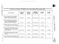
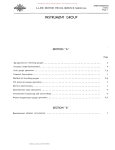
The following chart shows truck model, clutch model number, type of driven member, thickness and part number of spacer plate,
and release lever settings for R- LINE Chassis when using the SE-990 Clutch Overhaul Fixture.
-Ii
";;9 ~
=
~ 'll
i
TRUCK MODEL
IH CLUTCH
MODEL
NUMBER
TYPE OF
DRIVEN MEMBER
~.
~
R-ll0, R-120, R-130, R-lS0, RA-120,
RA-140, RM-120, RM-lS0 Series
Chassis (10" Rockford Clutch) •.•.•
SPACER
THICKNESS
AND NUMBER
A
LEVER
SETTING
B
LEVER
SETTING
C
¢l
RK-I0-B
Cushion
S/16" (CR-99)
l-S/S"
c·
z
1-lS/16"
[T1
3:
R-ll0, R-120, R-130, R-lS0, RA-120,
RA-140, RM-120, RM-lS0 Series
Chassis with SD-220 Engine (11"
Rockford Clutch with 9 Springs) . . . .
R-11A-I
Cushion
S/16 11 (CR-99)
1-11/16"
2"
::0
R-160, RC-160, R-170 Series Chassis
(11" Rockford Clutch with 12 Springs).
R-llA-l
Cushion
S/16" (CR-99)
1-11/16"
2" ~
~
(')
7'
U>
R-170, RC-lS0, RF-170 Series Chassis
and R-lS0, R-lS1, R-lS2, R-lS3,
R-lS4 Chassis (12" Rockford Clutch
with 12 Springs) • • • . . . . . . . . • . . .
RR-12-12
Cushion
3/S" (CR-S4)
1-S3/64 11
R-18S, R-lSS3, R-190, R-191, R-192, R-194 (12 11 Rockford Clutch with IS Springs) . • . . . . . . . . • • • . . . . • . .
RK-12-1S
Cushion
3/S" (CR-84)
I-S3/64 11
~n
2-13/64"
[T1
2-13/64 11 ------
R-190, R-200, R-210, RF-190, RF-210 Series Chassis (14" Rockford Clutch).
RK-14-15
Solid
47/64 11 (CR-71)
2-S/32"
. . ....... . .. til
------
t"1
nO
ItIjr<
Ploe:
OQ
z I-i
0
I.>J>:C
(l)
Donated by John & Susan Hansen - For Personal Use Only
CLUTCH
III
HI
R·LINE MOTOR. TRUCK SERVICE
Section A
Page 4
INNER HOLE PROVIDES HIGHER PEDAL PRESSURE WITH LESS PEDAL TRAVEL .
OUTER HOLE PROVIDES LOWER
PEDAL PRESSURE WITH GREATER
PEDAL TRAVEL
r
---L
RELEASE BEARING SLEEVE
i
l
RELEASE BEARING SLEEVE
A·30486
Fig. 3. Clutch Release Lever, Sleeve and Bearing. For R.150, R.160, R·170 series trucks, also R·180, R·181, R·182, R·1S3 and R.184 trucks. r...11----- LUBRICATOR
ELEASE BEARING SLEEVE
~
OUTER HOlE PROVIDES LOWER
PEDAL PRESSURE WITH GREATER
PEDAL TRAVel --'"'\.
,,
I
INNER HOlE PROVIDES '... r; ....".".
PEDAL PRESSURE WITH LESS
PEDAL TRAVEL ----..
RELEASE LEVER
A.30487
Fig. 4· Clutch Release Lever, Sleeve and Bearing. For R.185 to RF·210 trucks. Donated by John & Susan Hansen - For Personal Use Only
CLUTCHES
Section A
L-LINE MOTOR TRUCK SERVICE MANUAL
Page 1
CLUTCHES
Models RK-10B, R-llA-l, RK-12-12,RK-12-15, R-14-15, R-15-8
Fig. I (RK-IOB CLUTCH)
(a) Pressure plate to flywheel surface. . . . . . . . . . . . . . . . .
11/32 11
(b) Release lever to pressure plate surface. . . . . . . . . . . .. 1-15/32!T
(c) Release lever to flywheel surface . . . . . . . . . . • . . . . .. 1-13/16 11
H
G
Fig. 2 (R-11A-1 CLUTCH)
(a) Pressure plate to flywheel surface. . . . . . . . . . . . . . . . .
11/32"
(b) Release lever to pressure plate surface. . . . . . . . . . . .. 1-21/32"
(c) Release lever to flywheel surface . . . . . . . . . . . . . . . . .
PRINTED IN !JNITEO STATES OF AMERICA
2"
Donated by John & Susan Hansen - For Personal Use Only
CLUTCHES
Section A
Page 2
L-UNE MOTOR TRUCK SERVICE MANUAL
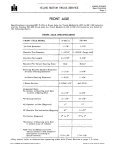
Fig. 3 (RK-12-12, RK-12-15 CLUTCHES)
(a) Pressure plate to flywheel surface. . . . . . . . . . . . . . . . .
(b) Release lever to pressure plate surface . . . . . . . . . . . . . .
1-3/4" (c) Release lever to flywheel surface • . . . • . . . . . . . • . . . .
2-1/8" Fig.
*
*
*-
3/8" ij (R-I~-15
CLUTCH)
(a) Pressure plate to flywheel surface (not shown). . . . . . . . .
15/32 11
(b) Release lever to pressure plate surface. . . . . . . . . . . ..
2-5/32"
(c) Release lever to flywheel surface (not shown) . . . . . . . . .
2-5/8"
(d) Cover plate mounting surface to pressure plate surface. . .
47/64"
Not shown in illustration.
Donated by John & Susan Hansen - For Personal Use Only
CLUTCHES
Section A
Page 3
L-LINE MOTOR TRUCK SERVICE MANUAL
-III •
~_
..
,:111&- ....
L
H
A-2JS75
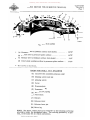
Fig. 5 (R-15-8 CLUTCH)
*
*
(a) Pressure plate to flywheel surface (not shown), , , , , , . , ,
15/32"
(b) Release lever to pressure plate surface . . . . . . . . . . . . .
2-9/32" (c) Release lever to flywheel surface (not shown) . . . . . . . . .
2-3/4"
(d) Cover plate mounting surface to pressure plate surface. . .
1-9/32"
* - Not shown
in illustration.
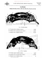
LEGEND FOR FIGS. 1 TO 5 INCLUSIVE
(A) Capscrew (for assembly purposes only)
(B) Adjusting screw lock nut
(C) Adjusting screw
(D) Cover
(E) Pressure plate
(F) Pressure spring
(G) Release lever spring
(H) Pivot block
(1) Rollers
(K) Release lever
(L) Release lever pin
(M) Drive lug
NOTE: The above clutch parts are referred to in the following serviCing procedure under the deSignated letter. The servicing procedure, in gen eral, is the same for all clutch assemblies. PRINTt::b IN UNITEO STATES OF A..,(JIl:ICA
Donated by John & Susan Hansen - For Personal Use Only
CLUTCHES
Section A
Page 4
L-UNE MOTOR TRUCK SERVICE MANUAL
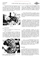
CLUTCH
Description
These clutches are of the single dry-plate
type, and release lever adjustments should not
be requi red during the normal life of the clutch
driven-plate facings. As pedal free-play is
reduced by wear of the clutch driven-member
facings, the correct amount of pedal free travel
should be re sto red by means of the pedal adjust
ment, which will also give the proper clearance
between clutch release levers and the release
bearing. It is extremely important to maintain
free travel of the pedal at all times to avoid
clutch slippage, and to protect throw-out bear
ing.
Whenever it is necessary to do any service
work on the clutch, advantage should be taken
of the opportunity to thoroughly recondition it.
This is a comparatively short job and will
assure satisfactory operation over a long period
-of time, whereas failure to do this may neces
sitate another tear-down within a short time.
capscrews holding the assembly compressed,
remove clutch from flywheel by backing out the
capscrews which hold it inplace. All capscrews
should be backed out gradually to avoid damage
to the clutch cover or back plate.
Driven Member Assembly
The clutch driven member assembly should
be carefully inspected. Facings showing con
siderable wear, or facings that are rough or
oil soaked, should be replaced.
When installing new facings of the continu
ous ring type, and in cases where two different
thicknesses are used on each plate, the thick
facing is installed on the pressure plate side.
The thin facing is installed on flywheel side.
Installation of clutch facings on the cushion
type driven member differs from the other type
in that each facing is attached to the discs sep
arately and independently (Fig. 7 and 8).
Removal
~--""Rivets
When removing transmission for the pur
pose of gaining access to the clutch, or for any
other reason, extreme care should be taken to
support the weight of the transmission until it
is completely removed so that the main shaft
splines will clear the driven member. Other
wise, there is a possibility of distorting the
driven member which will not permit a free
release of the clutch.
Capscrew "A"
For assemhly'
only
.
r
t
Fig. 7 - Solid type driven member,
secures both linings to disc.
/
Each
rivet
Rivets securing
thin facing
~.J;;:;::;::?-:::::;::::::::::-~
Segment
cushion
type disc
capscrews
•
A-21578
Fig. 6 - Instal I capscrews "A" before removing
clutch assembly. ~
The clutch pressure plate (E) is drilled
and tapped so that three capscrews (A) (see
specifications for sizes) with washers may be
inserted through the cover plate (D), thereby
holding the clutch assembly compressed when
it is removed or installed (Fig. 6). With three
A-21573
Fig. 8 - Cushion type driven member. Half of
the rivets hold thin facing and other half
secure thick facing to disc
Donated by John & Susan Hansen - For Personal Use Only
L-LlNE MOTOR TRUCK SERV1CE MANUAL
CLUTCHES
Section A
Page 5
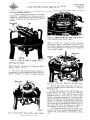
Clutch Overhauling Fixture
A clutch overhauling fixture is available
(Fig. 9) and is adapted to the overhaul and ad
justment of clutches used in International Motor
Trucks. Complete instructions accompany the
machine.
Fig. 11 - Spacer blocks are used when pressure
plate extends below clutch cover.
(Figs. 10 and 11). Center clutch assembly
over space plate. Draw fixture down to sur
face plate being sure fixture arms are seated
so as not to damage cover (Fig. 12). Compress
the assembly lightly.
Fig. 9 - Placing clutch in Sf-990 fixture.
Servicing the Clutch
NOTE: (Letter references in the text are those
shown in Figs. 1 to 5.)
The cover and pressure plate assembly is
dismantled by placing specified spacer plate or
spacer blocks on clutch overhaul machine
Fig. 12 - Draw clutch down with pulldown arms.
Fig. 10 -Use proper spacer plate, where needed,
PRINT£P IN UNITEO STATES OF AMERJC,A.
Remove the three capscrews (A) used to
hold the assembly while removing it from fly
wheel (Fig. 6).
Loosen and remove lock nuts (B) from ad
justing screws (C), Fig. 13. Screw adjusting
screws (C) out of cover (D) turning screws
clockwise three or four turns at a time while
slightly releasing pre>ssure on backing plate.
Repeat until pressure from the clutch pressure
springs is relieved and adjusting screws (C)
are free of cover (D). This procedure of grad
ually releasing the assembly and backing out of
the screws (C) must be followed in order to
avoid damage to the lever assemblies (K).
The clutch may then be fully re leased, afte r
which all parts are readily dismantled for in
spection and replacement if necessary. (Fig.
14.)
Donated by John & Susan Hansen - For Personal Use Only
CLUTCHES
Section A
Page 6
L-L1NE MOTOR TRUCK SERVICE MANUAL
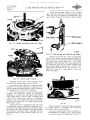
Clutch spring tester (Fig. 15) or similar
unit should be used for testing springs, (F).
They may also be tested by comparison with
new springs. Discard those not of same length.
spring
Scale (pounds)
Fig. 13 - Remove adjusting screw lock nuts.
A-22fT2
Fig. 15 - Check spr j ngs on SE-1565 Spr i ng tester.
Release levers (K) that show considerable
wear at the release bearing contact points as
well as at the pivot points should be replaced.
as should worn lever pins (L).
The lever
spring (G) should hold the lever adjusting screw
(C) and pivot block (H) up firmly against the
pivot points on the release levers. If this con
dition does not exist on the old levers. it is
sufficient reason for replacement with new
lever assemblies.
Fig.
I~ -
Clutch cover removed.
Remove cotter keys from release lever
pins (L) and remove pins and levers (K).
A pressure plate (E) that is badly scored,
checked or warped should be replaced, as it
will not pe rform satisfactorily, and in addition,
will damage the clutch driven member.
If the clutch surface on the flywheel is not
smooth, the flywheel should be removed,
mounted in a lathe and smoothed with emery
cloth using first a coarse cloth, finishing with
a fine cloth. Where the surface is extremely
rough, a light cut should be taken on the fly
wheel with a lathe tool, finishing and polishing
with emery cloth.
Clutch pressure springs (F) that have had
considerable service should be replaced, as it
is possible that they may have lost their origi
nal tension (see Specifications) and thus permit
the clutch to slip under load. Springs that are
discolored due to heat should always be re
placed.
A-22175
Fi g. 16
When overhauling clutch assemblies, where
no clutch fixture is available, the following
procedure will be found helpful:
The cover and pressure plate assembly is
dismantled by placing it on a drill press
or arbor press with supporting blocks of
Donated by John & Susan Hansen - For Personal Use Only
CLUTCHES
Section A
Page 7
L-LINE MOTOR TRUCK SERVICE MANUAL
wood or metal under pressure plate. (Fig.
16.) These blocks should not extend out
beyond the outside edges of the pressure
plate. (E). A bar is then placed across the
top of the cover assembly "D" and the drill
press or arbor press arm brought down to
a point where the assembly is compressed
slightly. From this point on, the same pro
cedure can be followed as used with the
special type clutch overhaul fixture pre
viously explained.
Clutch Release Levers
Hardened-steel, disc-type rollers (J)
used between the adjusting screw block (H)
lever (K) which reduces operating friction
relieves the stress on the adjusting screws
are
and
and
(C).
Assembling The Clutch (Using Clutch Overhaul
Fixture)
Place the clutch pressure plate (E) with
release levers assembled to plate on top of
specified spacer plate (Fig. lO or Fig. 11).
Installpressure springs (F) inposition on pres
sure plate (Fig. 14).
Place clutch cover or back plate
springs, making sure that springs
seated properly both above and below,
the adjusting screw holes in cover are
over the clutch lever adjusting screws
(D) over
(F) are
and that
directly
(C).
Draw fixture down to clutch cover or back
plate (D), Fig. 12, being sure fixture arms are
seated so as not to damage cover. The assem
bly can then be co:rnpressed slowly until the ~op
unthreaded portion of each adjusting screw (C)
can b~ guided by hand up through the tapped
holes m cover plate (D). At this point care
should be taken to see that both pressure plate
(E) and cover (D) are lined up correctly, so as
to permit free entry of the three drive lugs (M).
Turn each adjusting screw (C) up into
cover (D) approxi:rnately five turns at a ti:rne
(turning screw driver counter clockwise) and
after each five turns, co:rnpress the asse:rnbly a
s:rnall amount.
Fig. 17 - Checking lever setting.
FOR SERVICE STATIONS NOT EQUIP
PED WITH QVER'H.AUL FIXTURE, the follow
ing procedure may be used:
Place the pressure plate with release
levers assembled on supporting blocks on
drill or arbor press. From this point on,
same procedure as outlined in the above
paragraphs may be followed.
The release levers (K) may be adjusted to
correct setting as follows:
Adjust the pressure plate in relation to the
clutch cover as shown (Fig. 18). Use a
straight edge across the cover plate sur
face and, turning the capsc rews a small
amount at a time, secure di:rnension given
in specifications. Recheck this operation
several times to assure accurate adjust
ment.
Turb capscrews
.-
i~' adjusT
.
The release levers (K) :rnaynow be adjusted
to the correct setting as follows:
Clutch Release Lever Adjustments
The release levers (K) should be set to the
di:rnensions shown in Figs. 1 to 5. Lever ad
justing tool as shown in Fig. 17 can be used for
accurate adjust:rnent of levers. It is very i:rn
portant that all three levers be set exactly the
sa:rne height. After levers are set to the cor
rect height, the adjust:rnent lock nuts (B) are
installed and tightened securely. Care should
be taken not to upset the adjust:rnent when tight
ening the lock nuts.
PRINTED IN UNITED STATts OF AMERiCA
cover
A-21580
Fig. 18
Donated by John & Susan Hansen - For Personal Use Only
CLUTCHES
Section A
Page 8
L-UNE MOTOR TRUCK SERVICE MANUAL
The release levers are adjusted in a man
ner similar to that used when the "Clutch
Fixture" is available. Place the clutch assembly
on a flat surface and, with the adjusting screw
lock nuts loose, adjust the levers to secure
specified dimensions (Fig. 19). Recheck at
each lever to assure accuracy.
arrow is stamped on the outer flange of the
clutch cover which indicates the HEAVY side
of the clutch assembly
The clutch should be
assembled to the flywheel so that this mark is
adjacent to the mark "L!I stamped on the fly
wheel which indicates the LIGHT side. Fig. 20.
Bolt clutch assembly to flywheel making
sure that the marks on the flywheel and outer
flange of clutch cover match as nearly as pos
sible. This is important in order to maintain
the correct balance of the flywheel and clutch
assembly.
Remove the three capscrews (A) holding
the assembly compressed. The transmission
stub shaft or aligning bar is also removed, as
the driven-member assembly will now be held
in position by the clutch pressure plate. Care
should be exercised when installing the trans
mission, so as not to permit the transmission
to hang by the clutch shaft, which would bend
the hub of clutch-driven member, creating mis
alignment, with resultant clutch !ldrag ff •
Fig. 19
Installing Clutch
Figs. 21 to 25 inclusive illustrate clutch
and control installation.
When installing the clutch on flywheel in
truck, care should be taken to see that the
clutch driven-member is aligned properly by
inserting a transmission stub shaft or aligning
bar through the driven member splines and
into pilot bearing. Have dampener mechanism
of clutch driven member toward the transmis
sion. IMPORTANT: An inspection mark or
With transmission installed and floor
boards in place, make correct pedal adjust
ments. Do not adjust the clutch release levers,
which were previously set to the correct height
and require no further adjustment during the
life of the clutch-driven plate facings. Pedal
adjustments only are required to maintain the
recommended amount of pedal free travel. The
specified pedal clearance will assure proper
clearance between the clutch release bearing
and release levers. (Figs. 21 to 25 incl.)
NOTE: When installing the R-15-8 clutch
on the International Continental Engine fly
wheel, place the white paint marking on the
clutch cover as close to the letter !ILl! (light
side) on the flywheel as possible. The white
dab of paint on these clutch covers indicates
the heavy side of the clutch assembly.
Important
Fig. 20 - Showing use of aligning bar
when assembling clutch to flywheel.
or shaft
Oil and grease must be kept off the driven
member facings. The clutch release bearing is
lubricated at assembly and should require no
further lubrication during the life of the clutch
facings. If this bearing is removed for any
reason it should be examined and replaced if it
shows signs of lack of lubrication. The bearing
and retaining sleeve are available as a unit and
neither is furnished separately.
Donated by John & Susan Hansen - For Personal Use Only
L-LINE MOTOR TRUCK SERV1CE MANUAL
CLUTCHES
Section A
Page 9
Clutch Control Adjustment
Clutch Chatter
Figs. 21 to 25 inclusive illustrate the
assembly of the clutch control mechanism.
Clutch chatter cannot always be attributed
to the type of lining being used {molded or
woven}. It is generally chargeable to grease
or oil on the clutch facing, the source of which
may be:
The clutch pedal should have a specified
amount of free movement before clutch pres
sure is felt. (See Specifications or Figs. 21 to
25 inclusive). The clutch release bearing will
just touch the clutch release levers when the
clutch pedal is depressed the above amount.
If clutch pedal free movement is 1" or less,
adjustment is necessary to provide adequate
bearing-to-lever clearance.
As wear of the clutch facing takes place,
the clutch release levers move outward. reduc
ing the clearance between the clutch release
levers and clutch release bearing. The ad
justable yoke on clutch release rod provides
means of adjusting the clearance.
1. Failure to remove anti-rust grease from
the flywheel and pressure plate.
2. Excessive anti-rust grease in the cover
plate assembly.
When dismantling a clutch for service, the
flywheel, pressure plate, and cover plate
assembly should be thoroughly cleaned. If the
clutch facings show evidence of lubricant, they
should be replaced. It is impossible to remove
oil or grease from clutch facings with solvents
or by burning.
THE FOLLOWING PAGES - 10 to 14 inclusive ILLUSTRATE
CLUTCH INSTALLATIONS PRINTED IN UNITED STA T£S Of' AMERICA
Donated by John & Susan Hansen - For Personal Use Only
CLUTCHES
Section A
Page 10
L-UNE MOTOR TRUCK SERVICE MANUAL
Clutch pedal
For assembly purpose only
I
¥'\
il
I:,/A
E=!.'I
.~
D
:!
I
.
Pul,' back
I
spnng
~-~_-d
Release bearing sleeve
8,4563
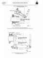
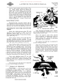
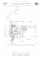
Fig. 21 - Control installation - L-IIO, l-120, L-130, L-150, L-153 Series.
A
I
B
11/32" 11-15/32"
C
1-13/16"
I
I
D
I 1 To 1-1/2
11
Donated by John & Susan Hansen - For Personal Use Only
L-UNE MOTOR TRUCK SERVICE MANUAL
CLUTCHES
Section A
Page 11
For assembly purpose only
Release bearing sleeve
Adjusting yoke
8·4562
Fig. 22 - Control Installation - LM-120, LM-150.
A
I
11/32"
I
B
I
c
D
1-15/32" ll-13/16 t1
1 To 1-1/2"
!
PRINTED IN UNITED STA't£S OF' AM£RICA
Donated by John & Susan Hansen - For Personal Use Only
CLUTCHES
Section A
Page 12
L-UNE MOTOR TRUCK SERVICE MANUAL
Clutch pedal
Adjustable yoke
Release sleeve
Release bearing
B.4564
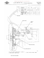
Fig. 23 - Control Installation - L-160, L-163,
L-16~,
L-165, LC-160 Series.
,
A
B
C
D
11/32"
1-21/32"
2"
1 To 1-1/2"
Donated by John & Susan Hansen - For Personal Use Only
CLUTCHES
L-UNE MOTOR TRUCK SERVICE MANUAL
~D~
~, ,
,
Section A
Page 13
!
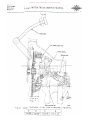
MODELS
L-170, L-173,
L-174. L-175,
LF-170
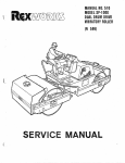
A
B
11/32" 1-21/32"
D
C
1
O/S FOR L-170 I
SERIES L-180, 25/64" 1-3/4"
L-183, L-184,
L-185
2"
1 to 1-1/2"
2-1/8" 1 to 1-1/2"
Clutch pedal
Release bearing
/
Pul! back
spnng
I
./
/j
L
n.\
( --,IN,
", ,I '
o.
,
Iii
II ..
I~'l-j ~
~\c ~
Adjusting yoke
i
l,\
----_.-_._--
\--.. _----------
I, l
I
,
~
I)
Release bearing sleeve
'I
I
'
1E~J_1111
I
-J
B
k-~
/
/1I
For assembly purpose only
)'
'-=-++=- /
Fig. 21t - Control Installation - l-170, l-173, l-171t, l-J75, LF-170, l-180,
l- 183, l-161t, l-185 Series.
PRrNTEO IN UNITED ST4TES OF" AMERICA
8-4561
Donated by John & Susan Hansen - For Personal Use Only
CLUTCHES
Section A
Page 14 L-UNE MOTOR TRUCK SERVICE MANUAL
Clutch pedal
'-------+--_.----
\..
I
Adjustable yoke
B.4691
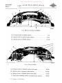
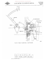
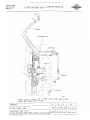
Fig. 25 - Control Installation - L-190, L-193,
L-200, L-20~, L-205, L-210, LF-210. L-19~,
L-195, LF-190, B
C
D
MODELS
A
L-190, L-193, L-194
3/81! 1-3/4"2-1/8" 1 To 1-1/2" !
O/S FOR L-190, L-194 15/32" 2-5/32" 2-5/8" 1 To 1-1/2"
L-195, LF-190, L-200, L-204, L-205, L-210, LF-210