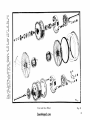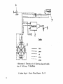
1
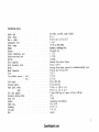
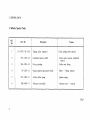
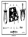
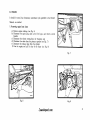
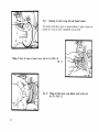
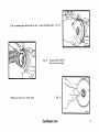
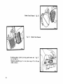
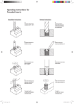
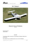
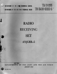
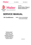
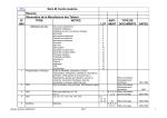
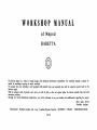
WORKSHOP
MANUAL
of Moped
BABETTA
The Babetta moped is a vehicle of simple design, with minimum maintenance requirements . The workshop manual is mainly intended for workshops carrying out major overhauls .
We assume that your workshop is well equipped with standard tools and naturally also with the respective special tools for the
Babetta moped .
With an adequate stock of genuine spare parts, you will be able to effect all repairs within the shortest possible time and with
maximum precision.
Through our Service Information Department, you will be informed of any new models and modifications regarding the moped .
After Sales Service
Povaiske strojarne
Manufacturer : Povaiske strojarne, Nat . Corp ., Povazska Bystrica Exporter :
1972
MOTOKOV - PRAHA - CZECHOSLOVAKIA
This copy provided free-of-charge by JawaMoped.com for your own personal use.
Not to be sold or used for any commercial purpose. Enjoy.
Printing Tip:- These pages are A5 size landscape.
If you want to print a copy, in printer set-up,
set to print full size - multiple page – vertically - 2 to an A4 sheet.
JawaMoped.com
Page
GENERAL INDEX
I . General Data
1.
2.
3.
4.
5.
Babetta Special Tools
Lubrication Chart .
List of Bearings and Seal Rings
List of Gears .
.
Transmission layout
4
6
8
10
12
II . Engine
1.
2.
3.
4.
Engine - Removing from Frame
Engine - Dismantling
Carburettor
Crankshaft
13
14
18
24
III . Frame
1 . Wheels,
Brakes
31
IV. Electrical Equipment
1 . Alternator .
2 . Wiring Diagram
3 . Tranz :mo Unit
2
32
33
35
TECHNICAL DATA
Engine type
Swept volume
Bore x stroke
Compression ratio
Power output
Clutch
.
.
Gearbox
Overall transmission ratio
Pedals-to-rear-wheel ratio
Starting
Front suspension
Front suspension stroke
Brakes
Brake dimensions
Tyres
.
Tyre inflation pressure - front
- rear
Curb weight .
Carrying capacity
Road speed, steady
peak
Fuel tank capacity
Maximum climbing ability
Noise level
.
.
Ignition
Spark plug
I Ieadlamp
Tail light
Bell
two-stroke, air-cooled, single cylinder
49 c . c.
39 X 41 mm (1 .55 X 1 .61")
1 to 6 .5
1 .5 HP at 4500 RPM
automatic, centrifugal, dry
One-speed unit
1 : 15 .75
1 : 0 .568
by pedals
telescopic fork without damper
60 mm (2 .36")
shoe-type drum brakes, operated by handlebar-mounted levers
85 X 20 mm (3 .35 X 0 .79")
23 X 2"
1 .75 atp
2 .25 atp
42 kg (92 .6 lbs)
90 kg (220 lbs)
35 km p . h . (32 m . p . h .)
40 km p . h . (25 . m . p . h .)
3 litres (2 .64 Imp . pt), reserve 0,5 litre (0 .88 pt)
10
73 dB
contact-less, semi-conductor
PAL 14-512
21W,6V
5 W, 6 V
smooth
3
JawaMoped . co m
I . GENERAL DATA
1 . Babetta Special Tools
Ref.
No.
Part. No.
1
16-19755-3S-U14
2
Description
Purpose
Tipping puller (remover)
Clutch sealing sleeve removal
975-1100-1 .2
Crankshaft remover (drift)
Clutch carrier removal, crankshaft
removal
3
928-1200-1 .2
Fitting cartridge
Guffero seal fitting
4
50-1200-1 .1
Gudgeon (piston) pin remover (drift)
Piston - fitting, removal
5
975-1400-1 .1
Advance feeler gauge
Ignition timing
6
928-6000-1 .1
Alternator rotor puller
Alternator rotor - removal
Fig . 1
4
J awaMoped . co m
2 . Babetta Moped Lubrication Chart
Ref.
No.
6
Lubrication point
Note
Lubricant
1
Engine
two-stroke engine oil SAE 30
(M 2 T)
upper engine lubrication . Oil petrol ratio 1 :30
2-
Gearbox
gear oil SAE 30-80 (PP80)
filling capacity 0 .13 litre
3
Steering
bearing grease (AV2)
on dismantling, wash and lubricate
4
Twist grip, throttle control
lubrication grease (A00)
5
Brake and decompressor
levers
SAE 30 oil (M6A)
6
Bowden controls
light oil
fill into bowden casings
7
Wheel hub bearings
bearing grease (AV2)
top up bearings
8
Brake cam lever pin, brake
cams, brake shoe fulcrum
pin
lubrication grease (A00)
after cleaning, provide with a light
grease coating
9
Chains
graphite grease oil (A00)
clean and lubricate, as necessary
10
Stand pin
SAE 30 oil (M6A)
11
Pedal bearings
SAE 30 oil (M6A)
12
Front fork telescopes
SAE 30 oil (M6A)
13
Idling run wheel
SAE 30 oil (M6A)
after washing, apply to sliding
parts
Fig . 2
J awaMoped . co m
3 . List of Bearings and Seal Rings
Ref .
No.
Part No.
I
Description
Dimensions
(mm)
PCs
Engine bearings
1
2
3
4
43204
43005
43006
28-2207
43001
Bearing 6203/C3
Bearing 6001/C3
Bearing 6004/C3
Primary transmission needle
rollers
Wheel hub bearings
Bearing 6001
17X 40X 12
12 X 28 X 8
20 X 42 X 12
2 X 12
12 X 28 X 8
2
2
2
26
4
Steering mounting
40001
Ball 5
42
Seal rings (Guffero)
5
6
7
8
9
10
8
50112
50102
50101
50115
50009
50305
Guffero seal
Guffero seal
Guffero seal
Guffero seal
Seal ring
Seal ring CSN 02 9281 .2
17 X 28 X
28 X 38 X
28 X 30 X
15 X 24 X
25 X 21
0 100 X
7
7
7
7
5
2
1
1
1
1
1
43005
6001/C3
OS
50112
17x28x7
04
28-2207
2x12
•
50112
17x28x7
i
€
50102
28x38x7
50101
20x30x7
c
50009
25x21
rl\
43204
6203 /C3
.10
.m
~O
43006
6004/C3
50305
100x 5
‚
50115
P)
15x24x7
Fig . 3
JawaMoped . corn
9
4 . Review of gears
Ser.
No .
Description
Number
of teeth
1
Gear
20
2
Gear
34
3
Gear
12
4
Gear
36
5
Sprocket
12
Sprocket
39
Fig . 2a Filling and discharging oil screw
1 . Filling hole screw
2. Discharge oil screw
3 . Control hole
Pedal transmissions
10
Sprocket
32
Idling sprocket
18
Fig . 4
J awaMoped . co m
It
5 . Transmission - Layout
1 .3,25
,r.
I
O'0
.1,201
z8.32
1
1 .0,568
I .6.39
MIS
x4 .36
M34
I
Fig . 5
92
II . ENGINE
It should be noted, that elementary maintenance jobs specified in the Driver's
Manual, are omitted.
1 . Removing engine from frame
a) Remove engine cowlings (see Fig . 6)
b) Disconnect the spark plug cable, petrol feed pipe, and throttle control
bowden
c) Disconnect the electric wiring from the Tranzimo unit
d) Disconnect the chain from the primary sprocket (see Fig . 7)
e) Disconnect the exhaust pipe from the cylinder
f) Free the engine, and pull it clear of the frame (see Fig . 8)
Fig. 7
Fig . 6
Fig . 8
J awaMoped . co m
13
Fig. 9
Slackening of clutch securing bolts and flywheel removal
The starting clutch plates require no special attention. A point of prime importance His to keep the clutch compartment dry and clean .
Pulling off sleeve by means of special service tool No. 16-19755-3S
Fig . 11
Fig. 10
14
Pulling off clutch carrier using Babetta special service tool
No . 975-1100-1 .2
Prior to removing the clutch drum, be sure to take out Seeger circlip
Fig . 12
Pulling seal ring out of clutch drum
Fig . 13
Starting clutch removal
Do not lose wire clips
Fig . 14
JawaMoped . com
15
Cylinder Barrel Removal Fig . 16
Fig . 15
Cylinder Head Removal
Removing gudgeon (piston) pin using special service tool
Fig. 17
No . 50-1200-1 .1
Maximum permissible gap of a worn piston ring is 0 .5 to 0 .6 mm
(0 .002 to 0 .024") .
16
Cylinder Grading Table
Diameter X H6
Standard
Rebore I
Rebore II
Reborn III
Rebore IV
39 .00+0 .016
39 .25+0 .016
39 .50+0 .016
39 .75+0 .016
40 .00+0 .016
I
A
39 .00+0 .006
39 .25+0 .006
39 .50+0 .006
39 .75+0 .006
40 .00+0 .006
B
C
39 .006+0 .005
39 .256+0 .005
39 .506+0 .005
39 .756+0 .005
40 .006+0 .005
39.011+0 .005
39 .261+0 .005
39.511+0 .005
39 .761+0 .005
40 .011+0 .005
B
C
Piston Grading Table
Piston Grading
A
1
39 .116-0 .006
39.106-0 .006
39 .111 -0 .005
39 .116-0 .005
Rebore II
39 .366-0 .016
39.356-0 .006
39 .361-0.005
39 .365-0 .005
Rebore III
39 .616 -0 .016
39.606 -0.006
39 .611-0.005
39 .616-0 .005
Rebore IV
39 .866-0 .016
39 .856-0 .006
39 .861-0 .005
39 .866-0.005
Rebore
J awaMoped . co m
17
3 . CARBURETTOR
The Babetta moped is provided with a JIKOV 2909 DC carburettor with the following technical specifications :
Main jet
Idling jet
Throttle needle
Fast idling screw
63
35
IInd notch from above
1'/2 turn
The basic maintenance of the carburettor comprises dismantling, flushing with clean petrol, and blowing dry with compressed air .
Be sure to clean the jet solely with petrol (or acetone) and air . Never use pieces of wire or any other hard items, in order to
avoid any hazard of damage to the calibrated holes .
In case of a more thorough overhaul of the carburettor, proceed as follows :
1 . Remove the carburettor from the engine, dismantle it, and clean thoroughly the individual components .
2 . Discard any worn parts and replace them with new ones .
3 . Check the flange for level face, and if pitted, true it on a piece of emery cloth placed on a flat surface .
4 . Having reground the carburettor body, clean it again thoroughly .
5 . Check the setting components for compliance with specifications . For checking, use the JSK 3 test station with the respective
attachments and scales, as follows :
a) For checking the main jet, use the hose attached to the extension marked A-D . Attach the general-purpose holder to
scale D .
b) When checking the idling jet, proceed in a similar manner, attaching the holder to scale A .
c) Check the carburettor throttle for wear with regard to the throttle chamber . The play must not be excessive, otherwise the
throttle is likely to vibrate (noisy operation, pinking) .
_
6 . Having reassembled the carburettor, check the needle valve for leakage . Attach the hose of the valve tester to the fuel feed
line, and turn the carburettor so as to close the needle valve . The tester must be set to a reading of 0 .4 kg/cm 2 (5.69 psi) .
The maximum permissible pressure drop is one graduation, i . e ., 0 .05 kg/cm 2 (0 .71 psi) per 5 seconds .
7 . Adjust the throttle needle and throttle stop screw as per specifications, and finish the assembly procedure .
8 . Install the carburettor in position on the engine . Start the engine, warm it up, and adjust the required mixture richness by
means of the air screw. Adjust the idling speed by means of the fast idling screw, and the twist grip play by means of the
bowden control . Adjust the throttle stop screw so as to ensure as regular operation of the engine as possible, with smooth transition points between idling and higher speed (RPM) .
1S
Fig . 18
JawaMoped . co m
19
Fig. 19
Releasing Alternator Cover Spring and its removing
Removing Alternator Rotor Using Special
Service Tool No. 16-65672-4 .3
Fig . 20 .
20
Fig . 21
Slackening Alternator Holding Bolt
Fitting Guffero Seal 17 X 28 X 7 Using Special Service Tool
No . 928-1200-1 .2
Fig . 22
Fig . 23
Removing Alternator Stator
Removing L-H Engine (Crankcase) Cover
Fig . 24
JawaMoped . co m
21
Fig. 25
Removing Primary Transmission Gear
Take care of the needle roller bearing .
26 needle rollers are fitted, the respective dimensions being 2X12
On fitting, grading according to the Table below is to be observed
Classing
Class
Fig . 26
22
0
2-0 .01
Dimension
1
0 2 .000-0 .002
2
0 1 .998-0 .002
3
0 1 .996 -0 .002
4
0 1 .994 -0.002
5
0 1 .992 -0 .002
Pulling Off of Gear Wheel
Fitting Gufero Seal in Position in Crankcase
Pressed Out Crankshaft c/w RH Crankcase Cover
Fig . 27
Fig . 28
Using Special Service Tool No . 928-1200-1 .2
Pressing Out Crankshaft From Crankcase Using
Special Service Tool No . 975-1100-1 .2
Pressing Out Crankshaft Fig . 29
JawaMoped . com
23
4 . Crankshaft
Dismantling and Reassembly
1 . To dismantle the crankshaft, use a press developing a pressure of approximately
5000 kg (11,023 lbs) . Prior to dismantling, mark the respective position of the
crankshaft flywheels by means of check marks (using a square) .
2 . Press out the crankpin first from one crankshaft web, and then_ from the other one .
3 . Renew the connecting rod, crankpin . and cage complete with rollers according to
the Grading Table .
4 . Thoroughly clean the crankshaft components, paying particular attention To the
journals, which must be perfectly dry .
5 . Press the crankpin home into the flywheel so that its face is just flush with the
flywheel outer face .
6 . Install the cage complete with rollers - lubricate with mineral jelly .
7 . Press fit the flywheel according to the check marks previously provided .
8 . After press-fitting, the crankshaft must be centred .
Crankshaft Alignment
Check the crankshaft for alignment and permissible out-of-round tolerances in a special jig (between centres), using two dial indicators . Clamp the crankshaft between
the centres so as to ensure free rotation . The maximum permissible peripheral out-of-true of the functional points is 0 .06 mm (0 .0024") . The shoulders for the bearings
are to be considered as functional points . Both the desing of the machine and the
respective production technology ensure the tolerance limits specified above . Be sure
to check the crankshaft for correct running (alignment) prior to fitting it to the
engine . In case of a new crankshaft, misalignment may be due to an accident, careless transport, dropping it on the ground, or possibly reconditioning of the shaft . To
ensure correct axial play of the crankshaft in the crankcase, adhere to the specification of 38-0 .2 mm (1 .496-0 .008") regarding the distance between the bearing
shoulders after press-fitting . Ensure a correct distance between the flywheels at the
point of crankpin, specified to a minimum of 12 .1 mm (0 .476") .
Fig. 30
24
ti
Crankshaft Alignment Procedure
Check axial alignment of the crankpins as per Fig . 30 . If the two crankshaft halves
are misalined (out of parallel), take the shaft from between the centres, place it on
a suitable pad (copper, aluminium), and using a hammer of soft material or possibly
a hand-operated crank press, proceed to align, until thee most correct axial alignment
of the crankpins is obtained .
The two crankshaft halves are not misaligned . if the readings of the two dial indicators are equal while the shaft turns . After this check (if the respective out-of-true of
the functional parts exceeds 0 .06 mm (0 .0024")), aling the centre line of the crankshaft by bending the two shaft halves, as necessary .
The procedure can be seen in Fig . 33, Ref . Nos . 2, 3 . According to the respective
misalignment of the crankshaft centre line (as per the dial indicator readings), bend
the flywheels so as to converge (in case of - - readings), or so as to diverge (in
case of + + readings) .
If necessary, proceed to align at several levels, not only as shown in the picture .
For final alignment, observe the specification 0 .06 mm (0 .0024") regarding the permissible out of true of the functional points . If this method fails to ensure the permissible tolerance limits in the peripheral out of true of the shoulder carrying the
drive gear of the primary transmission, the respective half the crankshaft is faulty
and must be replaced with a new one or reconditioned by grinding . Since this operation is considered rather exacting, it is advisable to entrust it to skilled craftsmen
only.
J awaMoped . co m
25
Table of Con-Rod Big End Grading
Connecting
rod
9
10
8
7
6
C
D
E
Roller
I
A
9
8
7
6
5
A
B
C
D
E
8
7
6
5
A
B
C
D
7
6
A
B
6 .7
5 .6
~
4 .5
B
I
C
Pin
Roller
II
I
Roller
III
I
5
I
4
IV
V
I
A
I
C
D
I
babetta
26
I
E
I
3
I
3 .4
D
Pin
I
Roller
I
E
2 .3
E
Pin
Pin
Roller
I
Pin
Detail of Engine
Drive Release Mechanism
Fig . 31
Fig . 32
Removing Control Gear
On fitting, be sure to lock the pin in position .
Removing drive Gear
Fig. 33
The change over switch pin be assembled so the pin grooves are between the
change over switch balls .
J awaMoped . co m
27
III . FRAME
Pedal Transmission - Removal
0
Fig . 35
AI-C.
Fig. 34
Removing Drive Gear Shaft
When replacing the bearings, it is advisable
to warm up the crankcase to approximately 80 €C .
MEW A
Front Telescope Plug - Removal Fig . 36
~hIIIII~I IIIIIII~7"
28
Front Telescope Nut - Slackening
Fig . 37
Front Telescope Slider (Plunger)
Fig . 38
Front Telescope Spring Retainer - Release
- Removal
Fig . 39
JawaMoped . co m
29
Fig . 40
Front Fork 30
Exploded View
c.
u
.. N
a
N
0 3
N
N
E
L
C7
a
€
a
a
ps
Q' 3
oio w ,b
,Y .N U
€
O' (1
C
w
u
N U
€
G
"
C
3
d F
Front and Rear Wheel
J awaMoped . co m
Fig . 41
31
IV . ELECTRICAL EQUIPMENT
1 . Alternator
Electric current is supplied from a 6-pole alternator of standardized unit design, with
ferrite basis .
The ignition system proper is contactiess . Instead of contact breaker arm, a trip coil
is fitted in the arm of the alternator stator .
Individual alternator circuits :
First circuit : Ignition feed pole, and primary (path indicator) coil of contact breaker
Second circuit : Headlamp and tail light feed pole
Bulbs : One PS 25-1, 6 V/21 W Ba 15s
One C 11, 6 V/5 W, SV 8 .5
32
Babetta Alternator
JawaMoped. com
Fig . 42
33
L.
€
6
€
' TRANZIMO
Cable :
black
green
red .
white
yellow
1 . Alternator . 2 . Tranzimo unit . 3. Sparking plug with cable
shoe . 4 . Tail lamp . 7. Headlamp
2 . Babetta Moped - Electric Wiring Diagram
34
Fig, 43
3 . Tranzimo Unit
MS-50 Moped Ignition Circuit
- Checking Procedure
1 . Check the spark length on a standardized three-electrode spark gap ; on starting.
a flashover of 6 mm (0 .23b") must occur . (Turn the engine with the spark plug
screwed in) . If the spark length is satisfactory, check the spark plug, or possibly the
cable shoe . If these components are sound, the fault is to be traced outside the ignition system .
2 . If the spark length is unsatisfactory, or if misfiring takes place, check the following
points :
a) Sound condition of the ,TRANZIMO" rear cap - if the cap is defective, replace
it with a new one and clean the area round the transistor .
b) Correct connection of the individual conductors to the semi-conductor part of the
TRANZIMO unit as per the Wiring Diagram .
c) Perfect connection in the connectors .
3 . If the fault persists, check the semi-conductor TRANZIMO part for sound condition,
by connecting a tested TRANZIMO unit to the connecting wires . If the spark is
now satisfactory, the defect is due to the semi-conductor part . If the fault still continues, the alternator is faulty .
4 . In the alternator compartment, check whether the wires are properly soldered to the
coil ends, or if they are not mechanically damaged . In addition, check the air gap
between the rotor and pole shoes . (0 .3 mm, i . e . 0 .012") . If no defect of this sort is
found, or if rectification of the respective defect has not helped, measure the feed
voltage as follows :
Disconnect
the
red wire from
the
TRANZIMO
unit,
charge
the
4 ,tF
(600 V capacitor via the KY705 diode, and check the capacitor voltage by
means of the Avomet-II . (DUIO) measuring unit . At 600 RPM of the engine,
i . e ., starting speed of the engine, a voltage of approximately 40 V must be ascertained . If the voltage is below this specification, or no voltage can be measured, the
feed (induction) coil must be replaced by a new one .
If the voltage of the feed (induction) coil is correct, check the voltage of the pulseforming coil in the same manner (white wire) - within a range of 3 V, the respective voltage must attain approximately 0 .3 V. If no voltage can be measured, the
entire stator frame with riveted-on starting coil must be replaced by new one .
5 . The semi-conductor part of the TRANZIMO unit can be repaired only if the fault is
due to the transistor itself - this can be ascertained by replacing the transistor with
a new one.
Interchanging of the wires soldered to the
transistor may result in deterioration of the
transistor . More over, care must be taken
not to overheat unduly the transistor
terminals on soldering .
Published by After - Sale Service Department .,
Pova2ske stroiarne . Povazska Bystrica - CSSR .
DTP 2963-71
35
JawaMoped . co m