1
Air Conditioner Edition:2006/1/10
CAUTION
READ THIS MANUAL CAREFULLY TO
DIAGNOSE TROUBLE CORRECTLY
BEFORE OFFERING SERVICE .
SERVICE MANUAL
Air Conditioners
MODEL: H2SM-(9+12)HV03/R2(DB)
H2SM-(9+9)HV03/R2(DB)
THIS MANUAL IS USED BY
QUALIFIED APPLIANCE
TECHNICIANS ONLY. HAIER
DOES NOT ASSUME ANY
RESPONSIBILITY FOR PROPERTY
DAMAGE OR PERSONAL INJURY
FOR IMPROPER SERVICE
PROCEDURES DONE BY ONE
UNQUALIFIED PERSON.
REVISION 0
Air Conditioner Edition:2006/1/10
IMPORTANT INFORMATION
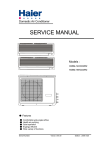
MODEL: H2SM-(9+12)HV03/R2(DB)
ƽҏFeatures
ƽҏComfortable: wide-angle airflow
ƽhealth air purifying
ƽquiet operation
ƽҏsuper energy efficient
ƽMain Specification
ƽCooling CapacityΚ 2600/3500/5300W
ƽRated Power/Current(cooling)Κ680/990/1600W/7.8A
ƽEER: 3.8/3.5/3.3W/W
ƽHeating CapacityΚ 3200/3800/6600W
ƽRated Power/Current(heating): 1185/1455/1930W/9.2A
ƽCOP: 2.7/2.6/3.4W/W
ƽAir Volume(Indoor): 500/550m3/h
ƽPower: 1PH 220-230V~ 50 Hz
Air Conditioner Edition:2006/1/10
IMPORTANT INFORMATION
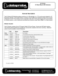
MODEL: H2SM-(9+9)HV03/R2(DB)
ƽҏFeatures
ƽҏComfortable: wide-angle airflow
ƽhealth air purifying
ƽquiet operation
ƽҏsuper energy efficient
ƽMain Specification
ƽCooling CapacityΚ 2600/5200W
ƽRated Power/Current(cooling)Κ680/1520W/7.5A
ƽEER: 3.8/3.29W/W
ƽHeating CapacityΚ 3200/6500W
ƽRated Power/Current(heating): 1185/1880W/8.8A
ƽCOP: 2.8/3.2W/W
ƽAir Volume(Indoor): 500m3/h
ƽPower: 1PH 220-230V~ 50 Hz
Air Conditioner Edition:2006/1/10
Safety Information
General Information
This Service Manual describes the operation,disassembly,troubleshooting,and repair of Haier Room Air
Conditioners,etc. It is intended for use by authorized servicers who troubleshoot and repair these units.
NOTE:It is assumed that users of this manual are familiar with the use of tools and equipment used to
troubleshoot and repair electrical,mechanical,and refrigeration systems;and understand the terminology
used to describe and discuss them.
Haier urges you read and follow all safety precautions and warnings contained in this manual. Failure
to comply with safety information may result in severe personal injury or death.
Related Publications
This is a base service manual,covering a range of similar models.It is intended to be used in
conjunction with the Parts Manual and Technical Sheet covering specific model being serviced.
General Precautions and Warnings
WARNING
To avoid risk of personal injury or death due to electrical shock,disconnect electrical power to unit
before attempting to service the unit.
WARNING
To avoid risk of personal injury or death due to electrical shock,DO NOT,under any circumstances,alter
the grounding plug .Air conditioner must be grounded at all times.Do not remove warning tag from power
cord.If a two-prong (non-grounding) wall receptacle is encountered,contact a qualified electrician and
have the receptacle replaced with a properly grounder wall receptacle in accordance with the National
Electrical Code.
WARNING
To avoid risk of personal injury or death due to electrical shock,grounding wires and wires colored like
grounding wires are NOT to be used as current carrying conductors.The standard accepted color coding
for ground wires is green or green with a yellow stripe.Electrical components such as the compressor
and fan motor are grounded through an individual wire attached to the electrical component and to
another part of the air conditioner.Grounding wires should not to be removed from individual components
while servicing,unless the component is to be removed and replaced.It is extremely important to replace
all removed grounding wires before completing service.
WARNING
To avoid risk of heat exposure,which may cause death or severe illness,air conditioner must be
monitored when malfunctions or shuts down.
Air Conditioner Edition:2006/1/10
CONTENTS
1. SPECIFICATION....................................1
2. ACCESSORIES......................................
3. OPERATION........................................
4. ELECTRICAL CONTROLL..............................
5. TROUBLE SHOOTING.................................
6. INSTALLA TION....................................
7. CIRCUIT AND WIRING DIAGRAM.......................
Air Conditioner Edition:2006/1/10
SPECIFICATION
1
Air Conditioner Edition:2006/1/10
Model˖ H2SM-(9+12)HV03/R2(DB)
Cooling Capacity:
2600/3500/5300(1300-6100)W
Rated Power/Current:
680/990/1600(380-2400)W/7.8A
Cooling
EER
Heating
Rated Power/Current:
-----
Frequency Range˖
50Hz
-------Power Cord
3200/3800/6600(1720-6960)W
Refer. No.˖
1185/1455/1930(480-2340)W/9.2A
10.4A
--------
Compressor
SANYO
manufacturer/Type
C-6RZ132H1A
Compressor
2.7/2.6/3.4
COP
220-230V~ 50 Hz
Model×Sectional Area˖
3.8/3.5/3.3W/W
Max Power/Current˖2360W/
1PH
Power
2530W/10.3A
Max Power/Current˖
Heating Capacity:
Brand Mark˖
320ml
Oil charge
Power/Current of
-----
R410A 1800g
Type/Net Charge˖
Electric Heating˖
Operating temp. range
H:
Additional Charge for
-7OC-43OC
1200/1250
Refrigerant
0g
exhausting air.
Charge if over Standrad
r/min
50g/m
Pipe Lenth
Indoor
1075
Velocity M˖
L˖
950
H˖
H˖
860
780
Velocity H˖
560
Outdoor
----
Lenth×Internal/External
r/min
Capilary
Diametre
r/min
Refer No.˖
r/min Height of rising
r/min
radiator slice
Indoor˖1.30
Outdoor˖
r/min
Indoor Weight
Air
----
mm
1.8
mm
Net˖
8.6kg
Gross˖
10.8kg
Net˖
49kg
Gross˖
53kg
Outdoor Weight
Volume Indoor˖
(High) Outdoor˖
Capacitor of Fan Motor˖
Class of electric Shock Protection
Class of Water Proof˖
Moisture Removal˖
Remote
Model:
Controller
Refer. No.˖
500(09)/ 550(12)
-----
3
m /h
795×265×182 mm
3
m /h Indoor Dimension(L×W×H)˖
……
ĉ
IP 24
1.2/2.4×10-3m 3/h
Indoor Packaging Dimension(L×W×H)
865x272x330 mm
Outdoor Dimension (L×W×H)˖
810×288×680 mm
Outdoor Packaging dimension(L×W×H)
960×405×760 mm
ij6.35/9.52 mm
liquid /Gas pipe Diametre
Refrigerant
YR-H76
Pipe
0010403792
5m
standard Lenth
Max Lenth
15
m
Remote Controller Bracket˖
-----
Lenth/Diametre of Drain Hose
----
Appearance˖
-----
Max. pressure at warm side˖
4.15
Climate Type˖
T1
Max.pressure at cool side˖
4.15MPa
Installation Bracket Type˖
-----
Plug Type(spec.)˖
---
Ammeter spec.˖
---
Area available for clooling/heating
15-23
Dry/Wet ball(indoor)˖ 32/
m
2
23 ć
Dry/Wet ball(indoor)/
Max.running
Max.running
temperature(cooling):
MPa
Dry/Wet ball(outdoor)˖43 ć/ 26 ć
2
Dry/Wet ball(outdoor):
temperature(heating):
ć --ć
Air Conditioner Edition:2006/1/10
Model˖ H2SM-(9+9)HV03/R2(DB)
Cooling Capacity:
Rated Power/Current:
2600/5200(1250-6000)W
Frequency Range˖
50Hz
EER
-------Power Cord
3200/6500(1620-6800)W
Refer. No.˖
1185/1880(420-2230)W/8.8A
10.3A
Max Power/Current˖2300W/
--------
Compressor
SANYO
manufacturer/Type
C-6RZ132H1A
Compressor
2.8/3.2W/W
COP
220-230V~ 50 Hz
Model×Sectional Area˖
3.8/3.29W/W
Heating Capacity˖
1PH
Power
2490W/10.2A
Max Power/Current˖
Heating
-----
680/1520(360-2300)W/7.5A
Cooling
Rated Power/Current:
Brand Mark˖
320ml
Oil charge
Power/Current of
-----
R410A 1800g
Type/Net Charge˖
Electric Heating˖
Operating temp. range
H:
Additional Charge for
-7OC-43OC
1200
Refrigerant
0g
exhausting air.
Charge if over Standrad
r/min
50g/m
Pipe Lenth
Indoor
1075
Velocity M˖
L˖
950
H˖
H˖
860
780
Velocity H˖
560
Outdoor
----
Lenth×Internal/External
r/min
Capilary
Diametre
r/min
Refer No.˖
r/min Height of rising
r/min
radiator slice
Indoor˖1.30
Outdoor˖
r/min
Indoor Weight
Air
----
mm
1.8
mm
Net˖
8.6kg
Gross˖
10.8kg
Net˖
49kg
Gross˖
53kg
Outdoor Weight
Volume Indoor˖
500 m
(High) Outdoor˖
Capacitor of Fan Motor˖
Class of electric Shock Protection
Class of Water Proof˖
Moisture Removal˖
Remote
Model:
Controller
Refer. No.˖
3
/h
-----
795×265×182 mm
3
m /h Indoor Dimension(L×W×H)˖
……
ĉ
IP 24
1.2/2.4×10-3m 3/h
Indoor Packaging Dimension(L×W×H)
865x272x330 mm
Outdoor Dimension (L×W×H)˖
810×288×680 mm
Outdoor Packaging dimension(L×W×H)
960×405×760 mm
ij6.35/9.52 mm
liquid /Gas pipe Diametre
Refrigerant
YR-H76
Pipe
0010403792
5m
standard Lenth
Max Lenth
15
m
Remote Controller Bracket˖
-----
Lenth/Diametre of Drain Hose
----
Appearance˖
-----
Max. pressure at warm side˖
4.15
Climate Type˖
T1
Max.pressure at cool side˖
4.15MPa
Installation Bracket Type˖
-----
Plug Type(spec.)˖
---
Ammeter spec.˖
---
Area available for clooling/heating
15-23
Dry/Wet ball(indoor)˖ 32/
m
2
23 ć
Dry/Wet ball(indoor)/
Max.running
Max.running
temperature(cooling):
MPa
Dry/Wet ball(outdoor)˖43 ć/ 26 ć
3
Dry/Wet ball(outdoor):
temperature(heating):
ć --ć
Air Conditioner Edition:2005/11/18
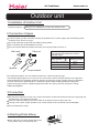
ACCESSORIES
4
Air Conditioner Edition:2006/1/10
H2SM-(9+12)HV03/R2(DB)
Failure
Quality
Remark
Rate(%)
Number
Name
Refer No.
Description
1
remote
controller
0010403792
None
1
0.2
2
battery
001A4600001
None
2
0.1
0010101274
Fix mounting plate
according to
installation position
and pipe direction
001A0900011
Choose the place
that can drain
water and connect
pipe easily
1
0.1
----
The maximal
length of the
connecting pipe is
15m,the maximal
height between
indoor unit and
outdoor unit is 5m
1
0.2
3
4
5
6
7
mounting
plate
drain pipe
connecting
pipe
connecting
wire
manual
----
001A7265614
The conecting
methods include
ring terminal and
direct
terminal .Ring
terminal
connecting
method:Unscrew
the screws ,and
put it through the
ring of connecting
line ends,then
connect it into the
terminal block.
Direct terminal
connecting
method:unscrew
the screws,then
fully insert the
cable ends into.
Operation
5
*
0
*
.
1
0.2
*
1
0
Air Conditioner Edition:2006/1/10
H2SM-(9+9)HV03/R2(DB)
Failure
Quality
Remark
Rate(%)
Number
Name
Refer No.
Description
1
remote
controller
0010403792
None
1
0.2
2
battery
001A4600001
None
2
0.1
0010101274
Fix mounting plate
according to
installation position
and pipe direction
001A0900011
Choose the place
that can drain
water and connect
pipe easily
1
0.1
----
The maximal
length of the
connecting pipe is
15m,the maximal
height between
indoor unit and
outdoor unit is 5m
1
0.2
3
4
5
6
7
mounting
plate
drain pipe
connecting
pipe
connecting
wire
manual
----
001A7265614
The conecting
methods include
ring terminal and
direct
terminal .Ring
terminal
connecting
method:Unscrew
the screws ,and
put it through the
ring of connecting
line ends,then
connect it into the
terminal block.
Direct terminal
connecting
method:unscrew
the screws,then
fully insert the
cable ends into.
Operation
6
*
0
*
.
1
0.2
*
1
0
Air Conditioner Edition:2005/11/18
OPERRATION
7
Air Conditioner Edition:2006/1/10
Cautions
Safety Instructions and Warnings
Disposal of the old air conditioner
Before starting the air conditioner, read the
information given in the User's Guide carefully. The User's Guide contains very important observations relating to the assembly,
operation and maintenance of the air
conditioner.
Before disposing an old air conditioner that
goes out of use, please make sure it's inoperative and safe. Unplug the air conditioner
in order to avoid the risk of child entrapment.
It must be noticed that air conditioner system
contains refrigerants, which require specialized waste disposal. The valuable materials
contained in an air conditioner can be recycled
.Contact your local waste disposal center for
proper disposal of an old air conditioner and
contact your local authority or your dealer if
you have any question. Please ensure that
the pipework of your air conditioner does not
get damagedprior to being picked up by the
relevant waste disposal center, and contribute
to environmental awareness by insisting on an
appropriate, anti-pollution method of disposal.
The manufacturer does not accept responsibility for any damages that may arise due
to non-observation of the following
instruction.
Damaged air conditioners are not to be
put into operation. In case of doubt, consult
your supplier.
Use of the air conditioner is to be carried
out in strict compliance with the relative
instructions set forth in the User's Guide.
Installation shall be done by professional
people, don't install unit by yourself.
Disposal of the packaging of your
new air conditioner
For the purpose of the safety,the air conditioner must be properly grounded in accordance with specifications.
All the packaging materials employed in the
package of your new air conditioner may be
disposed without any danger to the
environment.
Always remember to unplug the air
conditioner before openning inlet grill. Never
unplug your air conditioner by pulling on
the power cord. Always grip plug firmly and
pull straight out from the outlet.
The cardboard box may be broken or cut into
smaller pieces and given to a waste paper
disposal service. The wrapping bag made of
polyethylene and the polyethylene foam pads
contain no fluorochloric hydrocarbon.
All electrical repairs must be carried out
by qualified electricians. Inadequate repairs
may result in a major source of danger for
the user of the air conditioner.
All these valuable materials may be taken to
a waste collecting center and used again after
adequate recycling.
Consult your local authorities for the name
and address of the waste materials collecting
centers and waste paper disposal services
nearest to your house.
8
Air Conditioner Edition:2006/1/10
Cautions
Do not obstruct or cover the ventilation
grille of the air conditoner.Do not put fingers
or any other things into the inlet/outlet and
swing louver.
8. Young children should be supervised
to ensure that they do not play with
the applience.
9.Please employ the proper power plug,
which fit into the power supply cord.
Do not allow children to play with the air
conditioner.In no case should children be
allowed to sit on the outdoor unit.
10 .The power plug and connecting cable
must have acquired the local attestation.
11.In order to protect the units,please turn
off the A/C first, and at least 30 seconds
later, cutting off the power.
Specifications
The refrigerating circuit is leak-proof.
The machine is adaptive in following
situation
1.Applicable ambient temperature range:
Indoor
Cooling
o
o
Maximum:D.B/W.B 32 C/23 C
o
Minimum:D.B/W.B 18 C/14oC
o
o
Maximum:D.B/W.B 43 C/26 C
o
18 C
Outdoor Minimum:D.B
27oC
15oC
Indoor
Maximum:D.B
Minimum:D.B
Outdoor
o
o
Maximum:D.B/W.B 24 C/18 C
o
Minimum:D.B/W.B -15 C
Heating
2. If the power supply cord is damaged, it
must be replaced by the manufacturer
or its service agent or a similar qualified
person.
3. If the fuse of indoor unit on PC board is
broken,please change it with the type of
T. 3.15A/ 250V. If the fuse of outdoor
unit is broken,change it with the type of
T.25A/250V
4. The wiring method should be in line with
the local wiring standard.
5. After installation, the power plug should
be easily reached.
6. The waste battery should be disposed
properly.
7. The appliance is not intended for use
by young children or infirm persons
without supervision.
9
Air Conditioner Edition:2006/1/10
Cautions
Safety Instruction
Please read the following Safety Instructions carefully prior to use.
The instructions are classified into two levels, WARNING and CAUTION according to
the seriousness of possible risks and damages as follows. Compliance to the
instructions are strictly required for safety use.
Installation
WARNING
Please call Sales/Service Shop for the Installation.
Do not attempt to install the air conditioner by yourself because improper works
may cause electric shock, fire, water leakage.
lnstallation in a inadequate place may cause accidents. Do not install in the following place.
CAUTION
Connect the earth
cable.
Do not install in the Do not get the unit
place where there is exposed to vapor
any possibility of
or oil steam.
inflammable gas
leakage around the
unit.
Check proper
installation of the
drainage securely
earthing
PROHIBITION
PROHIBITION
10
STRICT
ENFORCEMENT
Air Conditioner Edition:2006/1/10
Cautions
WARNING
When abnormality such as burnt-small found,
immediately stop the operation button and
contact sales shop.
Use an exclusive power source with a
circuit breaker
STRICT
ENFORCEMENT
OFF
Connect power supply cord
to the outlet completely
STRICT
ENFORCEMENT
Do not use power supply cord
in a bundle.
PROHIBITION
Do not start or stop the
operation by disconnecting
the power supply cord and so on.
Use the proper voltage
STRICT
ENFORCEMENT
Take care not to damage
the power supply cord.
Do not use power supply cord
extended or connected in halfway
PROHIBITION
Do not insert objects into the air
inlet or outlet.
PROHIBITION
PROHIBITION
Do not channel the air flow directly
at people, especially at infants or
the aged.
Do not try to repair or reconstruct
by yourself.
PROHIBITION
PROHIBITION
CAUTION
Do not use for the purpose of storage of Take fresh air occasionally especially Do not operate the switch with
food, art work, precise equipment,
when gas appliance is running at the wet hand.
breeding, or cultivation.
same time.
STRICT
ENFORCEMENT
PROHIBITION
Do not install the unit near a fireplace
or other heating apparatus.
Check good condition of the
installation stand
PROHIBITION
Do not place animals or plants in
the direct path of the air flow
PROHIBITION
PROHIBITION
Do not pour water onto the unit
for cleaning
PROHIBITION
PROHIBITION
Do not place any objects on or
climb on the unit.
PROHIBITION
11
Do not place flower vase or water
containers on the top of the unit.
PROHIBITION
Air Conditioner Edition:2006/1/10
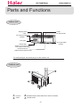
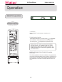
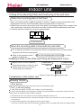
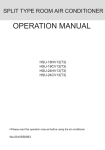
Parts and Functions
Indoor unit
Outlet
Air filter(inside)
Display board
Inlet
Air Purifying Filter
(inside)
Inlet grille
Anion generator
(inside)
Vertical flap
(adjust up and down air flow.
Don't adjust it manually)
Horizontal louver
(adjust left and right air flow)
For multi-split type, the power plug is on the outdoor unit
Outdoor unit
1
OUTLET
3 CONNECTING PIPING AND ELECTRICAL WIRING
2
INLET
4
DRAIN HOSE
12
Air Conditioner Edition:2006/1/10
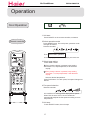
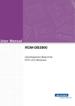
Parts and Functions
19
18
34
11
15
23
16
17
11. TIMER ON display
12. FAN SPEED display
LOW
HI
MED
AUTO
13. LOCK display
14. SWING UP/DOWN display
15. SLEEP display
16. HEALTH display
17.FRESH AIR display
28
FRESH
18. Operation mode display
POWER/SOFT
Operation mode
33
AUTO COOL
DRY
HEAT FAN
Remote controller
Display board
19.Singal sending display
20. POWER/SOFT display
21. Left/right air flow display
22. TEMP display
Remote controller: to display the TEMP. setting.
1.CODE
Used to select CODE A or B with a press,A or B
will be displayed on LCD.
Please select A without special explanation.
23. TIMER OFF display
24. CLOCK display
25. TEMP button
Used to select your desired temperature.
2.RESET
26. FAN button
When the remote controller appears abnormal,
use a sharp pointed article to press this button
to reset the remote controller normal.
Used to select fan speed: LOW,MED, HI, AUTO.
27. HEALTH AIRFLOW button
Used to set the health airflow mode.
3.LIGHT button
28. SWING UP/DOWN button
Control the lightening and extinguishing of
the indoor LED display board.
Used to select up or down air sending direction.
29. SWING LEFT/RIGHT button
4. TIMER button
Used to select left/right air flow.
Used to select TIMER ON, TIMER OFF,
TIMER ON-OFF.
30. FRESH button
5. CLOCK button
Use to set fresh air function.
Used to set correct time.
31. SET button
6. SLEEP button
Used to confirm timer and clock settings.
Used to select sleep mode.
32. POWER/SOFT button
33. LOCK
7. MODE button
AUTO
COOL
DRY
FAN
Used to lock buttons and LCD display. If pressed, the
other buttons will be disabled and the lock condition
display appears. Press it once again, lock will be
canceled and lock condition display disappears.
HEAT
8. HOUR button
Used to set clock and timer setting.
34. Ambient temp.display
9. HEALTH button
Used to set healthy operation.
When receiving the remote control signal, display the set
temperature and in the rest time the room temperature is
displayed and this room temperature is only for reference.
10. ON/OFF button
Used for unit start and stop.
NOTE:(1) The following functions and related displays are not available: 17 30
(2) Cooling only unit do not have functions and displays related with heating.
13
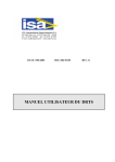
Air Conditioner Edition:2006/1/10
Parts and Functions
Clock Set
When unit is started for the first time and after replacing batteries in
remote controller, clock should be adjusted as follows:
FRESH
1. Press CLOCK button,"AM" or "PM" flashes.
2. Press or
to set correct time. Each press will increase or decrease
1 min. If the button is kept depressed, time will change quickly.
3. After time setting is confirmed, press SET, "AM" or "PM" stop flashing,
while clock starts working.
Remote controller's operation
When in use, put the signal transmission head directly to the receiver hole on the indoor unit.
The distance between the signal transmission head and the receiver hole should be within
7m without any obstacle as well.
Don't throw or knock the remoter controller.
When electronic-started type fluorescent lamp or change-over type fluorescent lamp or
wireless telephone is installed in the room, the receiver is apt to be disturbed in receiving
the signals, so the distance to the indoor unit should be shorter.
Loading of the battery
Load the batteries as illustrated right
2 R-03 (7#) batteries
Remove the battery cover:
Slightly press" "area and push down the cover
as illustrated.
Load the battery:
Be sure that the loading is in line with the "+" / "-".
request as illustrated on the bottom of the case.
Put on the cover again.
Confirmation indicator:
After pressing power ON/OFF, if no display, reload the batteries.
Note:
Full display or unclear display during operation indicates the batteries have been used up.
Please change batteries.
Used two new same-typed batteries when loading.
If the remote controller can't run normally during operation, please remove the batteries and
reload several minutes later.
Hint:
Remove the batteries in case unit won't be in usage for a long period. If there are any display
after taking-out, just need to press reset key.
14
POWER/SOFT
Air Conditioner Edition:2006/1/10
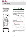
Operation
HEALTH operation
Remote controller
1.Unit start
Press ON/OFF on the remote controller, unit
starts.
2.Health anion function
Press HEALTH button. For each press,
is displayed.
Air conditioner starts health anion function operation.
For twice press,
disappears,the operation stops.
When indoor fan motor is running, it has healthy
process function. (It's available under any mode)
When the fan in the indoor unit does not work, the
health lamp lights up, but the anion generator does
not release anion.
FRESH
POWER/SOFT
BRIEF INTRODUCTION TO HEALTH ANION
FUCTION
The anion generator in the air conditioner can generate a
lot of anion effectively balance the quantity of position and
anion in the air and also to kill bacteria and speed up the
dust sediment in he room and finally clean the air in the
room.
15
Air Conditioner Edition:2006/1/10
Operation
Auto Operation
Remote controller
1. Unit start
Press ON/OFF on the remote controller, unit starts.
2.Select operation mode
Press MODE button. For each press, operation mode
changes as follows:
Remote controller:
AUTO
Then
COOL
DRY
FAN
HEAT
Select Auto operation
On the displaying board,colorful displaying bar will be white.
3.Select temp.setting
Press TEMP. button
Every time the button is pressed, temp.setting
increase 1oC,if kept depressed, it will increase
rapidly
Every time the button is pressed, temp.setting
decrease 1oC,if kept depressed, it will decrease
rapidly
FRESH
Select a desired temperature.
4.Fan speed selection
POWER/SOFT
Press FAN button. For each press, fan speed changes
as follows:
Remote controller:
LOW
MED
HI
AUTO
Air conditioner is running under displayed fan speed.
When FAN is set to AUTO, the air conditioner
automatically adjusts the fan speed according to room
temperature.
5.Unit stop
Press ON/OFF button, the unit stops.
About Auto Operation
Under the mode of auto operation, air conditioner will
automatically select Cool or Heat operation according
to room temperature.
16
Air Conditioner Edition:2006/1/10
Operation
Cool Operation
1. Unit start
Press ON/OFF on the remote controller, unit starts.
Remote controller
2.Select operation mode
Press MODE button. For each press, operation mode
changes as follows:
Remote controller:
AUTO
COOL
DRY
FAN
HEAT
Then Select COOL operation
On the displaying board,colorful displaying bar will be blue.
3.Select temp.setting
Press TEMP. button
Every time the button is pressed, temp.setting
increase 1oC,if kept depressed, it will increase
rapidly
Every time the button is pressed, temp.setting
decrease 1oC,if kept depressed, it will decrease
rapidly
FRESH
Select a desired temperature.
Press FAN button. For each press, fan speed changes as
follows:
POWER/SOFT
4.Fan speed selection
Remote controller:
LOW
MED
HI
AUTO
Air conditioner is running under displayed fan speed.
When FAN is set to AUTO, the air conditioner
automatically adjusts the fan speed according to room
temperature.
5.Unit stop
Press ON/OFF button, the unit stops.
17
Air Conditioner Edition:2006/1/10
Operation
Dry Operation
1. Unit start
Press ON/OFF on the remote controller, unit starts.
Remote controller
2.Select operation mode
Press MODE button. For each press, operation mode
changes as follows:
Remote controller:
AUTO
COOL
DRY
FAN
HEAT
Then Select DRY operation
On the displaying board,colorful displaying bar will be
light blue
3.Select temp.setting
Press TEMP. button
Every time the button is pressed, temp.setting
increase 1oC,if kept depressed, it will increase
rapidly
Every time the button is pressed, temp.setting
decrease 1oC,if kept depressed, it will decrease
rapidly
Select a desired temperature.
FRESH
POWER/SOFT
4.Fan speed selection
Press FAN button. For each press, fan speed changes as
follows:
Remote controller:
LOW
MED
HI
AUTO
Air conditioner is running under displayed fan speed.
In DRY mode, when room temperature becomes
lower than temp.setting+2oC,unit will run intermittently
at LOW speed regardless of FAN setting.
5.Unit stop
Press ON/OFF button, the unit stops.
18
Air Conditioner Edition:2006/1/10
Operation
Fan Operation
1. Unit start
Press ON/OFF on the remote controller, unit starts.
Remote controller
2.Select operation mode
Press MODE button. For each press, operation mode
changes as follows:
Remote controller:
AUTO
COOL
DRY
FAN
HEAT
Then Select FAN operation
On the displaying board,colorful displaying bar will be pink.
3.Fan speed selection
Press FAN button. For each press, fan speed changes as
follows:
Remote controller:
FRESH
LOW
POWER/SOFT
MED
HI
4.Unit stop
Press ON/OFF button, the unit stops.
About FAN operation
In FAN operation mode, the unit will not operate in
COOL or HEAT mode but only in FAN mode ,AUTO is
not available in FAN mode.And temp.setting is disabled.
In FAN mode,SLEEP and POWER/SOFT operation is
not available.
19
Air Conditioner Edition:2006/1/10
Operation
Heat Operation
Remote controller
1. Unit start
Press ON/OFF on the remote controller, unit starts.
2.Select operation mode
Press MODE button. For each press, operation mode
changes as follows:
Remote controller:
AUTO
COOL
DRY
FAN
HEAT
Then Select HEAT operation
On the displaying board,colorful displaying bar will be red
3.Select temp.setting
Press TEMP. button
Every time the button is pressed, temp.setting
increase 1oC,if kept depressed, it will increase
rapidly
Every time the button is pressed, temp.setting
decrease 1oC,if kept depressed, it will decrease
rapidly
Select a desired temperature.
FRESH
POWER/SOFT
4.Fan speed selection
Press FAN button. For each press, fan speed changes as
follows:
Remote controller:
LOW
MED
HI
AUTO
Air conditioner is running under displayed fan speed
IN HEAT mode, warm air will blow out after a short period
of the time due to cold-draft prevention function.
When FAN is set to AUTO, the air conditioner
automatically adjusts the fan speed according to room
temperature.
5.Unit stop
Press ON/OFF button, the unit stops.
20
Air Conditioner Edition:2006/1/10
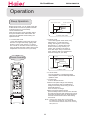
Operation
Air Flow Direction Adjustment
1.Status display of air sending
Vertical flap
Horizontal louvers
Pos.1
Pos.1
Pos.2
Pos.2
Pos.3
Pos.3
Pos.4
Pos.4
Pos.5
Pos.5
FRESH
POWER/SOFT
Pos.6
(Auto swing)
Pos.6
Pos.7
Pos.8
2.Up and down air flow direction
For each press of
button, air flow direction on remote controller displays
as follows according to different operation modes:
COOL/DRY/FAN
:
remote
controller:
Pos.1
Pos.2
Pos.3
Pos.4
Pos.6
HEAT:
remote controller:
Pos.5
Pos.4
Pos.3
Pos.2
Pos.1
Pos.6
AUTO:
remote controller:
Pos.1
Pos.2
Pos.3
Pos.4
Pos.5
Pos.6
The vertical flap will swing according to the above positions
3.Left and right air flow direction
For each press of
remote controller:
Pos.1
Pos.2
button, remote controller displays as follows :
Pos.3
Pos.4
Pos.5
Pos.6
Pos.7
Pos.8
The horizontal louvers will swing according to the above positions.
Note:When restart after remote turning off, the remote controller will automatically
memorize the previous set swing position.
21
Air Conditioner Edition:2006/1/10
Operation
Sleep Operation
SLEEP operation starts
SLEEP operation stops
Approx.6hrs
Before going to bed, you can simply press the
SLEEP button and unit will operate in SLEEP
mode and bring you a sound sleep.
Use of SLEEP function
After the unit starts, set the operation status,
then press SLEEP button before which the
clock must be adjusted and time being set.
Operation Mode
1 hr
Rises 1OC
Rises 1OC
1 hr
Unit stop
Temp.setting
In COOL, DRY mode
2. In HEAT mode
1 hours after SLEEP mode starts, temp
will become 2 OC lower than temp.
setting. After another 1 hours, temp
decrease by 2 OC further. After more
another 3 hours, temp. rises by 1OC
further. The unit will run for further 3
hours then stops. Temp. is lower than
temp. setting so that room temperature
won't be too high for your sleep.
1. In COOL,DRY mode
1 hours after SLEEP mode starts, temp. will
become 1OC higher than temp. setting. After
another 1 hours, temp. rises by 1OC further.
The unit will run for further 6 hours then stops.
Temp. is higher than temp. setting so that room
temperature won't be too Iow for your sleep.
Temp.setting
Remote Controller
1 hr
Unit stop
Decreases 2OC
1 hr
Decreases 2OC
3 hrs
3 hrs
Rises 1OC
SLEEP
operation stops
SLEEP
operation starts
In HEAT mode
3. In AUTO mode
The unit operates in corresponding sleep
mode adapted to the automatically selected
operation mode.
4. In FAN mode
It has no SLEEP function.
5.Set the wind speed change when sleeping
If the wind speed is high or middle before
setting for the sleep, set for lowing the wind
speed after sleeping.
If it is low wind, no change.
6.Note to the power failure resume:
press the sleep button ten times in five seconds
and enter this function after hearing four sounds.
And press the sleep button ten times within five
seconds and leave this function after hearing
two sounds.
FRESH
POWER/SOFT
NOTE: With the power failure resume, when setting
the TIMER ON, TIMER OFF and TIMER ON/OFF,
itís memorized as shutdown status when resuming
after power out.
22
Air Conditioner Edition:2006/1/10
Operation
Timer On/Off Operation
Set clock correctly before starting TIMER operation.
Remote Controller
1. After unit starts, select your desired operation mode
Operation mode will be displayed on LCD.
2. Timer mode selection
Press TIMER button to change TIMER mode. Every
time the button is pressed, display changes as follows:
Remote controller:
BLANK
TIMER ON
TIMER OFF
TIMER ON-OFF
Then select your desired TIMER mode (TIMER ON or
TIMER OFF). "
"or "
"will flash.
3.Time setting
FRESH
POWER/SOFT
Press HOUR
button.
Every time the button is pressed, time setting
increases 1 min, if kept depressed, it will increase
rapidly.
Every time the button is pressed, time setting
decreases 1 min, if kept depressed, it will decrease
rapidly.
It can be adjusted within 24 hours.
4.Confirming your setting
After setting correct time, press SET button to confirm
"
"or"
"on the remote controller stops flashing.
Time displayed: Unit starts or stops at x hour x min.
(TIMER ON or TIMER OFF).
5.Cancel TIMER mode
Just press TIMER button several times until TIMER
mode disappears.
Hints:
After replacing batteries or a power failure happens, time setting should be reset.
Remote controller possesses memory function, when use TIMER mode next time,
just press SET button after mode selecting if time setting is the same as previous one.
23
Air Conditioner Edition:2006/1/10
Operation
Timer On-Off Operation
Remote Controller
Set clock correctly before starting TIMER operation.
1. After unit starts, select your desired operation mode
Operation mode will be displayed on LCD.
2. Timer mode selection
Press TIMER button to change TIMER mode. Every time
the button is pressed, display changes as follows:
Remote controller:
BLANK
TIMER ON
TIMER OFF
TIMER ON-OFF
Then select your desired TIMER mode (TIMER ON - OFF).
"
"will flash.
3.Time setting
Press HOUR
button.
Every time the button is pressed, time setting increases
1 min, if kept depressed, it will increase rapidly.
Every time the button is pressed, time setting decreases
1 min, if kept depressed, it will decrease rapidly.
It can be adjusted within 24 hours.
4.Timer confirming for TIMER ON
After setting correct time, press TIMER button to confirm
"
" on the remote controller stops flashing.
"
" starts flashing.
Time displayed: Unit starts or stops at x hour x min.
FRESH
POWER/SOFT
5.Time setting for TIMER OFF
Just press HOUR button ,follow the same procedure in
"Time setting for TIMER ON"
6.Time confirming for TIMER OFF
After time setting,press SET button to confirm.
"
" on the remote controller stops blinking.
Time displayed:Unit stops at x hour x min.
To cancel TIMER mode
Just press TIMER button several times until TIMER
de disappears.
According to the Time setting sequence of TIMER ON
or TIMER OFF, either Start-Stop or Stop-Start can be
achieved.
24
Air Conditioner Edition:2006/1/10
Operation
POWER/SOFT Operation
POWER Operation
When you need rapid heating or cooling, you can use this funciton.
Selecting of POWER operation
Press POWER/SOFT button. Every time the button is pressed,display
changes as follows:
BLANK
POWER
SOFT
Stop the display at
In POWER operation status:
In HEAT or COOL mode, fan speed automatically runs in HI mode
for 15 min then returns to original status setting.
To cancel POWER operation
Press POWER/SOFT button twice ,POWER/SOFT disappears.
SOFT Operation
FRESH
You can use this function when silence is needed for rest or reading.
Selecting of SOFT operation
Press POWER/SOFT button. Every time the button is pressed,display
changes as follows:
BLANK
POWER
SOFT
Stop the display at
In SOFT operation mode, fan speed automatically takes"LOW"
To cancel SOFT operation
Press POWER/SOFT button twice ,POWER/SOFT disappears.
Hints:
During POWER operation, in rapid HEAT or COOL mode, the room
will show inhomogeneous temperature distribution.
Long period SOFT operation will cause effect of not too cool
or not too warm.
25
Air Conditioner Edition:2006/1/10
Operation
Health airflow Operation
1.Press ON/OFF to starting
Remote controller
The liquid crystal will display the working state of last time
(Except timer, sleeping, power/soft and health airflow).
Setting the comfort work conditions.
2.The setting of health airflow function
1).Press the button of health airflow,
appears on the
display. The nether inlet and outlet grills of the air conditioner are closed and the airflow is blown horizontally from
the above inlet and outlet grills. Avoid the strong airflow
blows direct to the body.
2).Press the button of health airflow again,
appears on
the display. The above inlet and outlet grills of the air conditioner are closed and the airflow is blown vertically from the
nether inlet and outlet grills. Avoid the strong airflow blows
direct to the body.
3.The cancel of the health airflow function
FRESH
POWER/SOFT
Press the button of health airflow again, both the inlet and
outlet grills of the air conditioner are opened, and the unit
goes on working under the condition before the setting of
health airflow function.
After stopping, the outlet grille will close automatically.
Notice: Cannot pull direct the outlet grille by hand. Otherwise,
the grille will run incorrectly. If the grille is not run correctly,
stop for a minute and then start, adjusting by remote controller.
Note:
1 .After setting the health airflow function, the position of inlet
and outlet grills is fixed.
2.In heating, it is better to select the
mode.
3.In cooling, it is better to select the
mode.
4.In cooling and dry, using the air conditioner for a long time
under the high air humidity, a phenomenon falling drips of
water occurs at the outlet grille .
5.Select the appropriate fan direction according to the actual
conditions.
26
Air Conditioner Edition:2006/1/10
Operation
Emergency and Test Operation
Emergency operation:
Use this operation only when the remote controller
is defective or lost.
When the emergency operation switch is
pressed,the" Pi "sound is heard once, which means
the start of this operation.
In this operation, the system automatically selects
the operation modes, cooling or heating, according
to the room temperature.
Temperature Operation Designated
mode
temperature
Timer
mode
Air flow
ABOVE 21OC COOLING
24OC
NO
AUTOMATIC
BELOW 21OC HEATING
24OC
NO
AUTOMATIC
It is not possible to operate in dry mode.
Test operation:
Test operation switch is the same as emergency switch.
Use this switch in the test operation when the room
O
temperature is below 16 C, do not use it in the normal
operation.
Continue to press the test operation switch for more
than 5 seconds. After you hear the "Pi" sound twice,
release your finger from the switch: the cooling operation
starts with the air flow speed "Hi".
After 30 minutes, test operation ends automatically.
Removal of the restriction of emergency or test operation
Press the emergency operation switch once more, or manipulate through the
remote controller; the "Pi" sound, the emergency or test operation is terminated.
When the remote controller is manipulated, it gets the system back to the
normal operation mode.
27
Air Conditioner Edition:2006/1/10
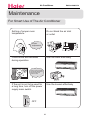
Maintenance
For Smart Use of The Air Conditioner
Setting of proper room
temperature
Do not block the air inlet
or outlet
Proper
temperature
Close doors and windows
during operation
Use the timer effectively
During cooling operation
prevent the penetration of
direct sunlight with
curtain or blind
Use the louvers effectively
If the unit is not to be used for
a long time, turn off the power
supply main switch.
OFF
28
Air Conditioner Edition:2006/1/10
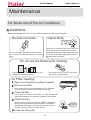
Maintenance
For Smart Use of The Air Conditioner
WARNING
Before maintenance,be sure to turn off the system and the circuit breaker.
Remote Controller
Indoor Body
Wipe the air conditioner by using a soft and
dry cloth.For serious stains,use a neutral
detergent diluted with water.Wring the water
out of the cloth before wiping.then wipe off
the detergent completely.
Do not use water, wipe the controller with a
dry cloth.Do not use glass cleaner or chemical
cloth.
Do not use the following for cleaning
O
O
Hot water over 40 C(104 F) may cause
discoloring or deformation.
Gasoline,benzine, thinner or cleanser may
damage the coating of the unit.
Air Filter cleaning
Open the inlet grille by pulling it upward.
Remove the filter.
Push up the filter's center tab slightly until it is released
from the stopper, and remove the filter downward.
Clean the filter.
Use a vacuum cleaner to remove dust, or wash the filter with
water.After washing, dry the filter completely in the shade.
Attach the filter.
Attach the filter correctly so that the "FRONT" indication is
facing to the front.Make sure that the filter is completely
fixed behind the stopper.If the right and left filters are not
attached correctly, that may cause defects.
Close the inlet grille.
29
Once every
two weeks
Air Conditioner Edition:2006/1/10
Maintenance
Replancement of Air Purifying Filter
1.Open the lnlet Grille
Open the inlet grille by pushing each ends of
the inlet grille upward.(use thumbs to push
up)
2.Detach the standard air filter
Slide the knob slightly upward to release the
filter, then withdraw it.
3.Attach old Air Purifying Filter
Put air purifying filter appliances into the
right and left filter frames.
4.Attach the standard air filter
(Necessary installation)
Detach old Air Purifying Filter
Note: the bacteria-killing mediums placed on the
left side. the multi-lights touching intermediary is
placed on the right side.
5.Close the Inlet Grille
Close the Grille surely
NOTE:
The photocatalyst air purifying filter and the bacteria-killing medium air purifying filter
will be used based on real situation.
The photocatalyst air purifying filter will be solarized in fixed time. In normal family,
it will be solarized every 6 months. The solarization time will last no less than 8 hours
under the state of abundant sun.
The bacteria-killing medium air purifying filter is available for a long time and neednít
to be changed. But it must be noticed to use the vacuum cleaner frequently to adsorb
the dusts covering the purifying filter lest the covering dusts effect the function of the
bacteria-killing medium air purifying filter. (It is strictly prohibited for the bacteria-killing
medium air purifying filter to be washed)
30
Air Conditioner Edition:2006/1/10
Maintenance
To Keep Your Air conditioner in Good Condition
after Season.
Operate in cooling mode for 2-3 hours.
To prevent breeding mold or bad smell, be sure to
operate at the designated temperature or 30OC,cooling
mode and High speed fan mode for 2-3 hours.
Put off the power supply cord.
Cleaning the body.
Take out the batteries from the
wireless remote controller.
31
Air Conditioner Edition:2006/1/10
Maintenance
Before Setting in High season
Cleaning the standard air filter.
Operation without filter may cause troubles.Be sure
to attach both right and left filters prior to the operation.
Each of them are of different shapes.
Connecting the earthing cable.
Caution
Incomplete earthing may cause an electric shock.
EARTHING
Do not block the air inlet or outlet.
Plug-in
Caution
After brush away dust at the plug, insert the
plug of the power supply cord into the outlet
completely.In case of suing exclusive circuit
breaker,switch on the circuit breaker.
32
NO WET HAND
Air Conditioner Edition:2005/11/18
ELECTRICAL CONTROLL
33
Air Conditioner Edition:2006/1/10
1. Operation Mode
1. Automatic operation
When the system is under the automatic operation option, the appropriate operation mode will
be decided according to the differences between the preset temperature and the indoor temperature
after the system starts up. Then, the system will operate according to the chosen mode. In the
following conditions, Tr stands for indoor temperature and Ts stands for outdoor temperature.
The system will choose the operation mode according to the following conditions when entering
into the automatic operation option for the first time.
Tr Ts-3
Choose the cooling mode
Tr Ts-3
Choose the warming mode
Under the automatic option, the system will switch between the cooling and warming modes
according to the change of the indoor temperature. If the air conditionic is under the cooling mode,
when the preset temperature for stopping the compressor is reached, the compressor will be stopped.
The indoor temperature will be tested again 15 minutes after the stop of the compressor. At the
moment, if the tested temperature is under the Tr Ts-3
condition, the system will be switched into the
warming mode. If not, the system will remain in the cooling mode. If the air conditionic is under the warming mode,
when the preset temperature for stopping the compressor is reached, the compressor will be stopped.
The indoor temperature will be tested again 15 minutes after the stop of the compressor. At the
moment, if the tested temperature is under the Tr Ts+8 condition, the system will be switched into the
cooling mode. If not, the system will remain in the warming mode.
2. Cooling operation mode
Temperature control range: 16 ---30
Temperature difference: ±1
* Control features: When Tr input airflow >Ts set temperature
, the outdoorunit will be
opened,the indoor fan will operate at the set speed and the mode signal will be sent to the outdoor
system. When Tr input airflow < Ts set temperature
, outdoorunit will be closed,the indoor
fan will operate at the set speed and the mode signal will be sent to the outdoor system. The system
will keep the original status if Tr= Ts.
Airflow speed control: (temperature difference 1 )
Automatic: When Tr>=Ts+3 , high speed.
When Ts+1 =<Tr<Ts+3 , medium speed
When Tr<Ts+1 , low speed
When the sensor is off, low speed
When the airflow speed has no delay from the high to low switching, the speed should be delayed
for 3 minutes (remain at high speed for 3 minutes.) before the next switch.
Manul: When the system is operating, you can set the high, medium or low speed manually. ( When
the sensor is on or off, the system will change the speed 2 seconds after receiving the signal.)
*Airgate location control: the location for the airgate can be set according to your needs.
*Defrosting function: preventing the frosting on the indoor heat exchanger (when cooling or
demoisture). When the compressor works continuously for 5 minutes (adaptable in EEPROM) and the
temperature of the indoor coils has been below zero centigrade for 10 seconds, the compressor will
34
Air Conditioner Edition:2006/1/10
be stopped and the malfunction will be recorded in the malfunction list. The indoor system will
continue to run. When the temperature of the indoor coil is raised to 7 , the compressor will be
restarted again (the prerequirement of 3 minutes delay should be satisfied.)
* timing system on/off function.
* Dormant control function.
3. Demoisture mode.
* temperature control range: 16---30
* temperature difference: ±1
Control feature: send the demoisture signal to the outdoor system.
When Tr>Ts+2 , the compressor will be turned on, the indoor fan will operate at the set speed.
When Tr is between the Ts and Ts+2 , the outdoor system will operate at the high demoisture
frequency for 10 minutes and then at the low demoisture mode for six minutes. The indoor fan will
operate at low speed.
When Tr< Ts, the outsystem will be stopped, the indoor fan will be stopped for 3 minutes and
then turned to the low speed option.
All the frequency converses have a 1
difference.
* Wind speed control: Automatic:
When Tr >= Ts+ 5 , high speed.
When Ts+3 ≤Tr< Ts+5 , medium speed.
When Ts+2 ≤Tr< Ts+3 , low speed.
When Tr<Ts+2 , light speed.
If the outdoor fan stopped, the indoor fan will be paused for 3 minutes.
If the outdoor fan stopped for more than 3 minutes and the outdoor system still operates, the system
will be changed into light speed mode.
When the airflow speed has no delay from the high to low switching, the speed should be delayed
for 3 minutes (remain at high speed for 3 minutes.) before the next switch.
Manual: When the sensor is off or Tr< Ts+3 , the manual operation can not be made. (obligatory
automatic operation.)
*Airgate location control: the location for the airgate can be set according to your needs.
*Defrosting function: preventing the frosting on the indoor heat exchanger (when cooling or
demoisture). When the compressor works continuously for 5 minutes (adaptable in EEPROM) and the
temperature of the indoor coils has been below zero centigrade for 10 seconds, the compressor will
be stopped and the malfunction will be recorded in the malfunction list. The indoor system will
continue to run. When the temperature of the indoor coil is raised to 7 , the compressor will be
restarted again (the prerequirement of 3 minutes delay should be satisfied.)
* coil protection (synchronic overheating protection) are installed for the four directions latch
malfunctions when demoisturing.
* timing system on/off function.
* Dormant control function.
35
Air Conditioner Edition:2006/1/10
4. Heating operation mode.
* temperature control range: 16---30
* temperature difference:
±1
* control feature: the temperature compensation is automatically added and the system will send
the heating signals to the outdoor system.
If Tr≤Ts, the outdoor compressor is turned on, the indoor fan will be at the cold air proof
mode.
If Tr>Ts+, the outdoor system is turned off, the indoor fan will be at the heat residue sending
mode.
If Tr<Ts+, the outdoor system will be turned on again, the indoor fan will be at the cold air
proof mode.
*Indoor fan control
manual control: You can choose high, medium, low and automatic speed control.
Automatic: When Tr<Ts, high speed.
When Ts=<Tr=<Ts+2 , medium speed.
When Tr> Ts+2 , low speed.
When the airflow speed has no delay from the high to low switching, the speed should be delayed
for 3 minutes (remain at high speed for 3 minutes.) before the next switch.
*Airgate location control: the location for the airgate can be set according to your needs.
36
Air Conditioner Edition:2006/1/10
Coldair proof operation
1. The indoor operation within 4 minutes after the start up is as the following diagram, the
air speed can be raised only after the speed has reached a certain level.
Set speed
Heat start temp 1
Low
Keep the high
Heat start temp 2
speed. The fan
Light speed
Heat start temp 3
doesn’t stop
Fan/off
Heat start temp 4
Fan/off
2. 4 minutes after the start up of the indoor fan, the light airflow and the low airflow will
be turned to the set speed airflow.
3. In the cold air proof operation, the fan won t stop after the start up.
4. During the cold air proof operation, the indoor system will continuously send indoor high
speed
signals to the outdoor system.
* Residue heat sending. The indoor fan will send the residue heat at a low speed for few seconds.
If other conditions are satisified, when the compressor stops, the indoor system will operate at
a light speed. The indoor fan will stop when the coil temperature is below the heat start temp
4 .
* Defrosting. When the system receives the defrosting signal from outdoors, the indoor fan will
stop and the indoor temperature display won t change. At the time, any indoor coil malfunctions
will be neglected. When the outdoor defrosting finishes, the coil malfunction will still be neglected
until the compressor has been started up for 30 seconds. The indoor temperature display will not
change and the system operates at the cold air proof mode.
* Automatic heating temperature compensation: when the system enters the heating mode, the
temperature compensation will be added. When the status is switched off, the compensation will be
erased.
2. Power operation
a. the system enters the mode after receiving the power signal .
Send power operation signal to the outdoor system.
power operation for 15 minutes.
The power operation stops or finishes after the 15 minutes.
The mode change finishes the power operation.
Entering soft , you can have normal operation or signal control such as timing to finish the
power operation.
When the system is at the automatic option with the power/ soft function, if the system enters the
cooling mode, the cooling power/ soft function will be offered; if the system enters the heating
mode, then the heating power/ soft function will be offered; if the system enters the airflow mode,
there will be no power/ soft function.
37
Air Conditioner Edition:2006/1/10
3. Soft operation
the system enters the mode after receiving the
soft signal .
a. soft heating: the airflow speed is slight, the system sends the soft signal to the outdoor system.
b. soft cooling: the airflow speed is slight, the system sends the soft signal to the outdoor system.
When the compressor operates, the airflow speed is soft speed. EEPROM is adaptable.
soft operation can not work under the demoisturing and airflow-sending operation.
4. Health operation
After receiving the signal from the remote control,(HV series: the background lighting is green
the health logo on. HS series: the health indicator will be lighted). If the fan operates,
the negative ion generator operates to realize the negative sending function.
If the indoor fan stops, the negative ion generator is turned off.
When the negative ion generator is turned off, if the health system is turned on, the negative ion
generator will be turned on when the fan operates.
5. Timing.
You can set 24 hours on/off timing accordingly. After the setting, the timing indicator will be
lightened. Also, the light will be turning off after the timing is finished. The followings are
several timing methods.
1.1 system /on timing: The timing indicator will be lightened and the indoor system is under
the waiting mode. The light will be turned off when the timing is finished and the rest of the system
will operate under a normal condition. The timing starts since the last reception of the timing
singal. You can have the dormacy setting under the timing mode, the order of your settings will
be operated according to the timing settings.
1.2 system /off timing: When the system is turned on, the timing indicator is lightened, the rest
of the system will operated under a normal condition. When set time comes, the indicator light will
be turned off and the system will be turned off. If you have set the dormant functions, the order
of your settings will be operated according to the timing settings.
1.3 system /on and off timing: The settings will be completed according to the orders.
6. sleep operation
The sleep timing is an eight hours unadaptable one. The timing signs are shown on the V series board. (RC series
show the sleep logo, HS series the timing light is lighted).
2.1 Under the cooling/ demoisture operation, after the setting of the sleep operation, the set temperature
will be raised for 1 centigrade after 1 hour’s operation and will be raised for 1 centigrade 1 hour later. The
system will keep this status for 6 hours and then close.
2.2 Under the heating mode, after the setting of the sleep operation, the et temperature will fall 2 centigrades
after 1 hour’s operation and will fall 2 centigrades 1 hours later. 3 hours after the preceding operations, the
set temperature will be raised for 1 centigrade and the system will keep this status for 3 hours and then close
down.
2.3
During the dormant time, except the change of the system mode or a new press on the dormant setting keys,
the timing of the 8 hours dormancy will take the first timing as the start time, any presses on other keys will
not affect the original timing.
2.4 Indoor fan control under the sleep operation.
If the indoor fan is at the high speed before the sleep operation setting, the speed will be turned to medium after
38
Air Conditioner Edition:2006/1/10
the setting. If the fan is at the medium speed before the sleep setting, the speed will be turned to low after
the setting. If the fan is at the low speed before the sleep setting, the speed will not change.
7. manual switch input
7.1 Press the manual switch the buzzer will ring. The system will enter the automatic mode if you don’t press the
button for more than 5 seconds.
Under the system off mode, if you press the manual switch for 5 to 10 seconds, the system will start the test
operation.
Under the system off mode, If you press the manual switch for 10 to 15 seconds, the display screen will show the
resume of the last malfunction.
If the system is under operation, the press on the manual switch will stop it.
Under the system off mode, the display screen will show automatic running sign.
Under the system off mode, the system will not receive the remote control signal if the press on the manual
switch doesn’t last for 15 seconds or if the key is loosened.
7.2 emergency operation: If you press the manual switch for less than 5 seconds, the buzzer will
ring when you press the manual switch. The system will enter the emergency operation when the
manual switch is loosened. The emergency operation is fully automatic.
7.3 Test operation.
a. The inlet temperature sensor doesn t work, the indoor fan and the indoor air direction
board motor works synchronically. High speed airflow, cooling, outdoor system on, etc,
will send the ambient temperature 30 centigrade and coil temperature 16 centigrade
information to the outdoor system.
b. Test operation
The defrost protection of the evaporator doesn t work.
The temperature control doesn t work.
c. The test operation will be finished in 30 minutes.
d. The test operation can be stopped by the relative commands from the remote control.
8. Low load protection control
In order to prevent the frosting of the indoor heat interaction device, the outdoor
system will be stopped if the indoor heat interaction temperature is below zero
centigrade for 5 minutes, but the fan will continue to operate. The outdoor system will
be started again when the heat interaction temperature is above 7 centigrade and the
system has been stopped for 3 minutes. The malfunction will be stored in the malfunction
resume and will not be revealed.
9. High load protection control
The outdoor system will be stopped if the coil temperature is above 65 for 2 minutes.
The indoor fan will be controlled by the thermostat. The outdoor system can be restarted
when the coil temperature is below 42
and the system has been stopped for 3 minutes.
The malfunction will be stored in the malfunction resume and will not be revealed.
10. Abnormal operation of indoor system
When the outdoor system operates, if the indoor system operation differs from the outdoor system, the abnormal
39
Air Conditioner Edition:2006/1/10
operation malfunction will be reported. 30s after the report, the indoor system will be closed.
Outdoor system mode
Indoor system mode
conflicts
cooling
heating
yes
cooling
cooling
no
cooling
airflow
no
heating
heating
no
heating
airflow
yes
heating
cooling
yes
11. The last malfunction list resume.
Nothing is presented if there is no code list.
The malfunction display will automatically finish in 10 seconds.
The remote control only receives the sigals for stop. According to the signals, the malfunction
resume presentation finishes.
The resume restores after the power supply restores.
12. abnormality confirmation approaches.
17.1 indoor temperature sensor abnormality: under the operation, the normal temperature ranges from 120 degree to
-30 degree. When the temperature goes beyond this range, the abnormality can be confirmed. If the temperature goes
back into the range, the system will automatically resume.
17.2 indoor heat interaction sensor abnormality: under the operation, the normal temperature ranges from 120 degree
to -30 degree. When the temperature goes beyond this range, the abnormality can be confirmed. If the temperature
goes back into the range, the system will automatically resume.
17.3 transmission abnormality.
If the indoor system can’t receive the outdoor system for 8 minutes, the communication abnormality can be
confirmed and reported and the outdoor system will be stopped.
13. Special features
1)Single indoor system operation
* Enter condition: First, set the high speed airflow and 30 centigrade set temperature, then press
the dormant keys for 6 times within 7 seconds, the system will feedback with 6 rings.
* After the system enters the separate indoor system operation mode, the indoor system will operate
according to the set mode and neglect the communication signals of the outdoor system. However,
it has to send signals to the outdoor system.
* Quitting condition: This mode can be quitted after receiving the quitting signal from the remote
control or urgency system. The indoor system thus can quit the single operation mode.
2)Power cut compensation.
* Entering condition: Press dormant button 10 times within 7 second, the buzzer will ring 4 times
and the present system status will be stored into the EEPROM of the indoor system.
* After entering the power cut compensation mode, the processing of the indoor system should be
40
Air Conditioner Edition:2006/1/10
as the followings:
Remote control urgency singal: operate according to the remote control and the urgent conditions,
the present status will be stored into the EEPROM of the indoor system.
* Quitting conditions: Press dormant button 10 times within 7 seconds and the buzzer will ring twice.
14
Other additional functions.
1) Display function
1-1 HV series and LCD display
When the system starts up, the background and the LCD will be fully lighted for 3 seconds. The
background colour is white.
(1) Three-color background
The multi-color indicator is not lighted when the system is off. The mode-switching will change
the indicator colors. Red color is for heating mode, blue for cooling, water color for demoisturing,
white for automatic mode, pink for airflow sending, green for health mode and yellow green for air
refreshing. The colors health, refreshing colors are preferred to the mode colors. If different
status exist at the same time, then the last set color will be shown. The lighting key of the control
board can turn on or off the display.
(2) LCD display
*Set timing to display timing signs, set dormant mode to display dormant sign.(The dormant signs
will be shown on the G series panels.), set health mode to display health sign, set new airflow
mode to display new airflow sign and set violet disinfection to display health sign.
*Set auto, heating, demoisturing, heating to display the relative signs. When you use a remote
control to switch cooling, demoisturing and heating modes, the set temperature will be shown and
the screen board will return to the room temperature 5 seconds later. If you choose the airflow
sending mode, the screen board will show the room temperature directly.
*If the system is under malfunction status, the display will show the malfunction code. Please
refer to the malfunction list.
1-2 HS series lights display
When the system starts up, the six LED indicator lights will be lighted for 3 seconds. (operation, timing,
cooling, heating, demoisturing, health)
The operation light is lighted when the compress starts up.
When the system is under cooling, demoisturing or heating conditions, relative LED indicators
will be lighted. When the system enters heating mode, the heating light will be lighted. When the
system enters cooling mode, the cooling light will be lighted. When the system enters the airflow
sending mode, the operation light will be lighted, the heating, cooling and demoistruing light will
not be lighted.
When the timing is set, the timing light will be lighted. When dormant mode is set, the timing
light will be lighted. If the health mode is set, the health light will be lighted.
If the system is under malfunction status, the malfunction display will be shown in how many times
the indicator lights flash. Please refer to the malfunction list.
2). Malfunction display
41
Air Conditioner Edition:2006/1/10
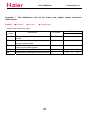
Appendix 1 The malfunction code for the indoor and outdoor system interaction
malfunctions.
Sample:
■ the led off
□ the led on
★ the led flashing
Indoor system malfunction codes
malfunctio
n codes
1#
2#
7#
14#
4#
malfunction
HV series
Indoor temperature sensor system
break
Indoor heat interaction temperature
sensor system break
Inefficient
communication
between
indoor and outdoor system
Indoor fan abnormality
Malfunction in reading or writing E2ROM
42
HS series
operation
heating cooling
E1
★
■
■
E2
★
□
□
E7
■
■
★
E14
E4
■
□
★
★
□
★
Edition:2006/1/10
Air Conditioner outdoor system malfunction code(the indoor unit can show you some malfunction code, as follow)
malfunctio
n codes
1#
2#
3#
4#
5#
6#
7#
8#
9#
10#
12#
13#
14#
15#
16#
17#
19#
21#
22#
31#
32#
HS series
malfunction
HV series
Ambient sensors circuit break
Hot temperature sensor circuit breaks or
shorts
Outlet temperature sensor circuit breaks
or shorts
DC compressor feedback.
Outdoor
system
communication
malfunction.
Current overcharge.
No load.
Overloaded/ under loaded voltage.
DC compressor failure.
Refrigerating overload
IPM protection
E2 ROM reading failure
E2 ROM coining failure
DC fan malfunction
NO AC power
Aspiration sensor circuit breaks
DC compressor speed control failure
Coil 1 sensor circuit breaks or shorts
Coil 2 sensor circuit breaks or shorts
System A communication malfunction
System B communication malfunction
F1
□
★
■
F2
★
□
□
F3
★
□
■
F4
★
■
□
F5
■
■
★
F6
★
■
★
F7
★
■
★
F8
■
★
□
F9
★
■
□
F10
★
★
★
F12
★
★
□
F13
★
□
★
F14
F15
★
□
★
F16
★
■
★
F17
□
□
★
F19
★
■
□
F21
□
□
★
F22
□
□
★
F31
■
■
★
F32
■
■
★
43
operation
heating cooling
-----
Air Conditioner Edition:2006/1/10
OUTDOOR SYSTEM FUNCTIONS
The outdoor system will decide the operation mode based on the principle of first order
preferred
according to the startup signals of the two indoor systems.
a) cooling: Under the cooling operation, the four direction latch will not be closed.
The outdoor fan will operate at the cooling mode. The compressor will operate under
the cooling frequency.
b) heating: Under the heating operation, the four direction latch will be closed. The
outdoor fan will operate at the heating mode. The compressor will operate under the heating
frequency. When frosts appear at the outdoor system, the system will enter into the
defrosting operation automatically. After the completion of the defrosting, the system
will be resumed.
1. heat defrosting operation
1.1 Under the heating operation, when the indoor heat interaction temperature is below the
ambient temperature and the heat interaction temperature is below zero centigrade, the
frosts will appear on the heat exchanger. When the aggregated frost affects the heat
interaction, the defrosting operation will begin.
1.2 frost confirmation condition. When either of the following condition appears, the system
will enter the defrosting mode.
b) continuous operation for 47 minutes and Ta 5 , if Te -3 for 2 minutes.
b) continuous operation for 47 minutes and Ta 5 , if Te -7
for 2 minutes.
c) continuous operation for 47 minutes and Ta -3 , if Te -9
for 2 minutes.
d) If Ta -3 and the compressor worked for 3 hours without a defrosting operation, the
system will process the defrosting for one time.
1.2.1 Defrosting process: After entering the defrosting operation, the compressor and the fan
will be stopped. The four direction latch will be opened 30 seconds later. And the compressor
will restart 10 seconds later. The system begins the defrosting operation.
1.2.5 defrosting quitting condition:
i) Time control: Defrosting time lasts 10 (EEPROM) minutes, the defrosting operation ends.
ii) Heat interaction control: When Te 14 (EEPROM), the defrosting operation ends.
1.2.6 Defrosting quitting process
After the completion of the defrosting, the compressor stops. 50 seconds later, the four
direction latch changes direction. 10 seconds later, the compressor will start and the original
heating operation resumes.
1.2.7 After the entering into the frosting mode, the compressor will operate at least for
1 minutes before stopping the defrosting. (The timing starts as the four direction latch
starts.)
1.3 Outdoor main relay control
The outdoor main relay closure will be delayed for 2 seconds after connecting to the circuit.
1.4 Outdoor airflow control
1.4.1 airflow control at the cooling mode.
After the compressor is turned on for 5 seconds, the outdoor fan will start at a high speed.
10 seconds later, the speed will be controlled according to the outdoor ambient temperature.
If the outdoor has only two option, M operates on H and L operates on L.
45
Air Conditioner Edition:2006/1/10
When the outdoor speed is M or L, the speed will change according to the heat interaction
temperature. The status will be checked every minute.
Ta>28
high speed
26 <Ta<28
high/ low speed
Ta<26
Te 40
high speed
37
Te<40
high/ medium speed
35
Te
medium speed
30
Te<35
medium/ low speed
Te<30
low speed
1.4.2 the speed control under the heating mode
The outdoor speed varies according to the outdoor ambient temperature. M operates on H under
the two option mode.
Ta =24
Ta =20
Ta =10
Ta =16
Outdoor speed
L
24
16
Ta>24
>Ta>20
Ta>16
>Ta>10
Ta<10
M
H
M
L
low speed
low speed/ medium speed
medium speed
medium/high speed
high speed
1.5 Outdoor four direction control
Under the cooling mode, the outdoor four direction latch is not closed. Under the heating mode,
the latch can be closed. When the heating compressor stops, the four direction latch will be
closed 100 seconds later. The latch control under the defrosting operation has been discussed
in the defrosting operation .
1.7 compressor frequency control
1.7.1 fixed test frequency
To fixing test frequency operation of the outdoor system.
the indoor system can be controlled manually. (refer to the indoor system specification).
1.7.1.1 If the indoor system has the fixed frequency test operation function, then the outdoor
system will calculate the fixed frequency according to the number of the turned on systems
and operate on the calculated frequency until the indoor system quit the test operation. When
the two indoor systems are turned on at the same time, the outdoor system will enter the
operation mode if either of the indoor systems sends the fixed test frequency.
46
Air Conditioner Edition:2006/1/10
i) The outdoor fixed frequency is set according to the indoor system signals. The operation
is on the frequency stored in EEPROM
ii) The cooling and heating value under the double system operation
Under the single system fixed frequency test, the outdoor system will operate according to
the turned-on indoor system status. The operation will on the frequency relative to the status.
Under the double system operation test, the outdoor system will automatically operates on the
double system fixed test frequency.
1.7.2 Normal operation frequency control
Under the outdoor system normal operation, the fixed frequencies of different indoor systems
should be tested according to the different capacity of the respective indoor systems. Then
the outdoor system will decide the operation frequency according to the fixed frequencies,
the difference between set temperature and the indoor temperature and the indoor fan speed.
1.8 malfunction and protection
1 8 1 Three minutes waiting mode protection
1) No matter caused by which condition, the outdoor compressor is not allowed to be restart
within 3 minutes after a compressor shut down.
2) If the compressor shut down is caused by malfunctions and the malfunction is corrected
3 minutes after, the compressor can restarted of the correction at once.
1.8.2 Intelligent power module protection.
i) Under the compressor operation, if the IPM protection happens under the voltage over/under
loading, over heating or current overcharge, the compressor will stop and restart 3 minutes
later.
ii) If the IPM protection happens 4 times continuously, the compressor will be totally turned
off and can be restarted only by a second connection to the power supply.
1.8.3 Sensor malfunction protection.
i) There are 6 sensors in the outdoor system. The outdoor system will stop if any of the six
sensors has malfunctions. The malfunction will be reported respectively.
ii) After the malfunction has been corrected for 3 minutes, the system can be restarted.
Outdoor restriction condition codes display:
When the outdoor system operates, because of the various temperature or electrical device
restrictions, the compressor has to ensure the maximal output within a safe frequency range.
This restriction condition only represent the most possible condition at the time, can only
be used as a reference in experiments.
1#
Normal, no restriction
2#
Power voltage restriction
3# outdoor heat interaction restriction under the cooling mode; indoor heat
interaction under the heating mode.
4#
main current restriction
5# outlet temperature restriction
6# indoor heat interaction temperature restriction. (frosting prevention)
7# Indoor fan speed restriction
8# Outdoor frequency conversing voltage restriction
1.8.4 The malfunction codes
47
Air Conditioner Edition:2006/1/10
After the stopping of the system, the flashing time of the LED02 is the malfunction
code.
For example
Malfunction N.O 4
2.5sec
1#
2#
3#
4#
5#
6#
7#
8#
9#
10#
11#
12#
13#
14#
16#
17#
19#
21#
22#
31#
32#
2.5sec
Ambient sensors circuit break.
Hot temperature sensor circuit breaks or shorts.
Outlet temperature sensor circuit breaks or shorts.
DC compressor feedback.
Outdoor system communication malfunction.
Current overcharge.
No load.
Overloaded/ under loaded voltage.
DC compressor failure.
Refrigerating overload.
Defrosting mode.
IPM protection.
E2 ROM reading failure.
2
E ROM coining failure.
NO AC power.
Aspiration sensor circuit breaks.
DC compressor speed control failure.
Coil 1 sensor circuit breaks or shorts.
Coil 2 sensor circuit breaks or shorts.
System A communication malfunction.
System B communication malfunction.
Dealing with the malfunctions
4#
Compressor feedback malfunction: Check the main board CN301 and the module jack CN3.
Check the CN04 on the main board and test the output of 15V DC current between the pins
of CN04. Check the location of the chip COM01 at the back of the mainborad, to see if
there is any circuit shorts. Check the states of the 3 phases of the modules. If the feedbacks
of all the checks and tests are normal, then replace COM01.
5# Outdoor system communication malfunction: check the module jack CN401 on the
main board, to see if the conducts of the jack are normally connected with
the terminal stripe. Test if there is a 5V DC current between the pin 8 and
pin 16 of IC03 on the main board. Check if the pin 3 and pin 13 of this chip
are correctly connected with the pin 44 and pin 45 of the IC01, to test if
there is any circuit shorts. Test if there is any communication wave output
at the pin 4 of PQ 404 and PQ 408 and at the pin 2 of PQ403 and PQ 407 and
if there is any circuit shorts on the systems of the surrounding devices ( the
misconnect between the live line and the zero line.)
6#. Current overcharge: Test if there is any circuit block on the system. Test the 4 diodes
48
Air Conditioner Edition:2006/1/10
D501-D504 on the main board with a multimeter. Test if there is any 5v circuit shorts at
R501-R503 and D-505. Replace device CT501.
7#. No load:
Test the 4 diodes D501-D504 on the main board with a multimeter. Test is there
is any circuit short with GND at R501-R503 and D505( special focus on the possible circuit
short condition the terminal A of D502 and terminal K of D504). To test if there is any
formation of resistance or GND circuit short at the capacitor C501. Replace device CT501.
8# Overloaded/ under loaded voltage: Test if there is 310V DC between the terminal P and N
of the program module. Test if there is any circuit short at R301-R304 , R324 and R325.
Test if there is any formation of resistance or GND circuit short at the capacitor C304.
9# DC compressor start-up failure: Please restart; Check if the input and output at 7805(IC04)
is correct. Check the status of the module on the module board. (the normal reading of the
diode mode on the multimeter should be 0.45 at the P, N, U, V, W disconnect
terminals.);Check the voltage of C4,C5,C6 on the module board is 15V or not.
10#. Refrigeration overload: the temperature of pipe is too high,if the malfunction is
reported frequency, check the refrigerant is enough or not.
11# Defrosting condition: After the completion of the defrosting, the system will return to
normal.
12#. IPM protection: check if the system circuits are at normal condition. Check if there is any
GND short at R08 on the main board, to test if there is any formation of resistance or GND
circuit short at the capacitor C02, or any other protection modes caused by temporal current
surge as a result of inappropriate operation or other reasons.
13# 14# malfunctions: Check if the installation of IC05 on the main is correct. (if the installation
is reversed), and if there is any break at the back of the main board. Replace IC05 directly.
16# No AC power: Check the power supply.
19#DC compressor speed control failure: Restart the compressor after it is turned of for a while.
If the restart doesn’t work, refer the suggestions of NO 9 and NO 4.
31# and 32# A/B system communication problem: please refer to NO 5 and check the indoor
system communication circuit.
vals can be controlled in E2.
49
Air Conditioner Edition:2005/11/18
TROUBLE
SHOOTING
50
Air Conditioner 2006/1/10
Trouble shooting
Before asking for service, check the following first.
Phenomenon
Cause or check points
The system does not restart
immediately.
When unit is stopped, it won't restart
immediately until 3 minutes have elapsed
to protect the system.
When the electric plug is pulled out and
reinserted, the protection circuit will work
for 3 minutes to protect the air conditioner.
During unit operation or at stop, a swishing
or gurgling noise may be heard. At first 2-3
minutes after unit start, this noise is more
noticeable. (This noise is generated by
refrigerant flowing in the system.)
During unit operation, a cracking noise may
be heard. This noise is generated by the
casing expanding or shrinking because of
temperature changes
Should there be a big noise from air flow in
unit operation, air filter may be too dirty.
Noise is heard
Normal
Performance
inspection
This is because the system circulates smells
from the interior air such as the smell of
furniture, cigarettes.
Smells are generated.
Mist or steam are blown out.
During COOL or DRY operation, indoor unit
may blow out mist. This is due to the sudden
cooling of indoor air.
Does not work at all.
Is power plug inserted?
Is there a power failure?
Is fuse blown out?
Multiple
check
Is the air filter dirty? Normally it should be
cleaned every 15 days.
Are there any obstacles before inlet and outlet?
Is temperature set correctly?
Are there some doors or windows left open?
Is there any direct sunlight through the
window during the cooling operation?(Use
curtain)
Are there too much heat sources or too many
people in the room during cooling operation?
Poor cooling
o
o
Application temp. range of air conditioner -7 C~43 C.
51
Air Conditioner Edition:2006/1/10
Abnormality Diagnosing
Number
1
2
3
4
Parts that may appear problems Prepared parts
Trouble
Description
phenomenon
and the Cause
and tools
7805,transformer, piezo
Use the resistance, fuse,remote controller, 7805,transfor
receiver. If it can be booted by
mer, fuse,
remote
piezo
controller to using manual emergency switch,
Not work with
that indicate the power cable and resistance,
boot
remote
wiring board are electriferousˈ
remote
machine
controller
remote controller or receiver isn’t
controller,
and it
well˗else check whether piezo receive,avome
doesn’t
resistance ,fuse and 7805 are
ter
work
wellDŽ
Optical SCR, indoor P.C. board.
Optical SCR,
Check the 2# and 4# terminal
indoor P.C.
Outdoor block of indoor unit, if it has 220V
board ,
fan motor voltage, wiring board is normal,
outdoor fan
Outdoor fan
doesn’t run then check whether the optical
motor
motor
when
SCR is good, replace it if it has
doesn’t work
capacitor,
cooling or flaw˗else check whether there are
outdoor fan
heating something wrong with connecting
motor,avomet
lineˈoutdoor fan motor capacitor
er
and coil assemblyDŽ
Optical SCRˈindoor P.C. board DŽ
Check whether indoor fan motor Optical SCRˈ
Indoor fan has 80-170V voltageˈif it hasˈ
indoor P.C.
motor wiring board is normal, then check board , indoor
Indoor fan
doesn’t run whether the optical SCR is good,
fan motor
motor
when
replace it if it has flaw˗else check capacitor,
doesn’t work
indoor fan
cooling or
whether there are something
heating wrong with connecting lineˈindoor motor,avomet
fan motor capacitor and coil
er
assemblyDŽ
Indoor P.C. board , four-way valve
coil, body of four-way valveˈCheck Indoor P.C.
the 2# and 3# terminal block of
board ,
indoor unit, if it has 220V voltage four-way valve
Cooling but
Not heating
when heating but no when cooling, coil, body of
not heating
then P.C. board is abnormal; else
four-way
check whether four-way valve coil
valve,
and the body of four-way valve are avometer
damagedDŽ
52
Applicable
machine
invariable
frequency
split unit
invariable
frequency
split unit
invariable
frequency
split unit
invariable
frequency
split unit
Air Conditioner Edition:2006/1/10
5
Drain pan, drain hose. Check
Oriented
whether the indoor unit is installed
wind panel
horizontal, drain hose of indoor
or drain
Indoor unit
unit is leveled off ,the hole is over
make water pan makes
high ˈfilter and drain hose is dirty
water when
and walled upǃdrain pipe is
used
underwaterDŽ
6
Indoor P.C. board , startup capacity
Indoor P.C.
running for compressor, overheat protector,
board , startup
indicator compressor. Check the 1# and 2#
capacity for
invariable
lights upˈ
terminal block of indoor unit
compressor,
Compressor
whether it has single AVˈif not then
frequency
but
overheat
doesn’t work
split unit
compressor examine the power relay of P.C.
protector,
board ˈelse check overheat
doesn’t
compressor,av
protector, startup capacity for
work
ometer
compressor and compressor itself
7
Remote controller ǃelectrolytic
capacitor of 2500UFǃ7805ǃ
outdoor heat exchanger sensor
Remote
and ambient temperature sensor. controller ,elec
The
Use temperature key of remote
trolytic
running
controller to watch how much
capacitor of
lamp of air
The outdoor
times the timing lamp glitters and
2500UFǃ
conditioner
Little split
judge what’s the trouble .If there is
7805ǃ
fan motor
lights but
unit of
and
no glitter we should check the
outdoor heat
the outdoor
frequency
compressor
terminal block to see if there is AC exchanger
fan motor
conversion
don’t work
voltage about 220V.Check the
sensor and
and
electrolytic capacitor of 2500UF
ambient
compressor
and see if there is current about temperature
don’t run
310V.Examine the output of the
sensorǃ
7805 and switch transformer
avometer
together with the resistance of the
sensor.
8
The outdoor
fan motor
runs but the
compressor
doesn’t run
The running
lamp of air
conditioner
lights ,the
outdoor fan
motor works,
but the
compressor
doesn’t work
drain pan,
drain hose
invariable
frequency
split unit
Power modelǃswitch transformerǃ
compressor. Check the temperature key
of remote controller to watch how many
Power modelǃ
times the timing lamp glitters and judge
Little split
switch
what’s the trouble. Examine the two
unit of
transformerǃ
ends of PN to see if there is DC voltage
frequency
compressorǃ
about 310V.Four group DC power
conversion
avometer
resource of 15V.Check the triphase coil
assembly of the compressor and see if
they are the same.
53
Air Conditioner Edition:2006/1/10
9
Don’t make
heat
10
Show error
code E8
11
Can’t start
12
Show error
code F11
Outdoor P.C. Boardǃ4 way valve
coilǃ 4 way valve body. Examine
the CN204 at Outdoor P.C. Board Outdoor P.C.
The air
and watch if there is 220V
Boardǃ4way Little split
conditioner
voltage .If there doesn’t have we valve coilǃ 4
unit of
can
refrigerate can judge that the P.C. Board is
way valve
frequency
but can’t
bad. If there has, we need to
bodyǃ
conversion
make heat connect and check the whether the avometer.
4 way valve coil and the 4way
valve body have been damaged .
Multimeter negative generatorǃ
Multimeter
indoor P.C. board ǃconnecting and
negative
The
inserting lines .Check if the
generatorǃ The series
machine Multimeter negative generator is
indoor P.C.
of
doesn’t
plane and the grounding (CF) is
Boardǃ
frequency
work and touching well, then examine not
control
fixed
shows error only whether the indoor P.C. Board board ǃ
cabinet
code E8
and control board have been
grounding
type
damaged or not but also the
(CF)ǃ
connecting lines are good.
avometer.
Transformerǃindoor
Transformerǃ The series
microcomputer plateǃfuse. Check
power wave
of
if the transformer has been
The air
filterǃindoor frequency
conditioner
burned. power wave filterǃ
microcompute
fixed
can’t start
LX102.Check whether the fuse
r plateǃfuseǃ cabinet
and indoor microcomputer plate
avometer.
type
have been damaged.
The system pressureǃoutdoor P.C.
BoardǃPower source voltageǃ
When the
power modelǃthe connecting lines
air
of compressor. The cause is that
conditioner
protective action has been taken outdoor P.C.
The
has run
when it runs with large burden, BoardǃPower machine of
about
there is more refrigerant than it
source
frequency
5minutes
should be .Examine the outdoor voltageǃpower conversion
the indoor
P.C. BoardǃPower source voltageǃ model .
split unit
unit shows
power model and see whether they
the error
have been damaged and the
code F11.
connecting lines touch well, if not,
adjust it to be normal.
54
Air Conditioner Edition:2005/11/18
INSTALLATION
55
Air Conditioner Edition:2006/1/10
Installation Manual of Room Air Conditioner
Read this manual before installation
Explain sufficiently the operating means to the user
according to this manual.
Necessary Tools for Installation
1.Driver
2.Hacksaw
3.Hole core drill
4.Spanner(17,19 and 26mm)
5.Torque wrench(17mm,22mm,26mm)
6.Pipe cutter
7.Flaring tool
8.Knife
9.Nipper
10.Gas leakage detector or
soap-and-water solution
11.Measuring tape
12.Reamer
Drawing for the installation of indoor and outdoor units
more than 5cm
The models adopt HFC free refrigerant R410A
Accessory parts
No.
1
2
Accessory parts
Remote controller
R-03 dry battery
6
7
Plastic cap
Drain-elbow
Cushion
m
Indoor unit B
Optional parts for piping
mo
re th
2
4X25
Screw
10c
Indoor unit A
Mark
Drain hose
5
an
4
Mounting plate
4
re th
2
2
3
mo
Number
of
articles
8
1
4
A
an
Parts name
m
Non-adhesive tape
B
Adhesive tape
C
Saddle(L.S) with screws
D
E
Connecting electric cable
for indoor and outdoor
Drain hose
F
Heating insulating material
G
10c
Attention must be paid to
the rising up of drain hose
C
Piping hole cover
m
an
Arrangement of piping directions
re th
re
tha
n1
Rear left
10c
mo
mo
0c
m
Rear
right
Left
Right
Below
m
an
60c
re th
mo
The marks from A to G in the figure are the parts numbers.
The distance between the indoor unit and the floor should be
more than 2m.
No.0010557180
56
more
than
15c
m
319.5
Air Conditioner Edition:2006/1/10
113.5
583
113.5
Floor fixing dimensions
of the outdoor unit
(Unit:mm)
Fixing of outdoor unit
Fix the unit to concrete or block with bolts( 10mm) and nuts firmly and horizontally.
When fitting the unit to wall surface, roof or rooftop, fix a supporter surely with nails
or wires in consideration of earthquake and strong wind.
If vibration may affect the house, fix the unit by attaching a vibration-proof mat.
Indoor Unit
Selection of Installation Place
Place, robust not causing vibration, where the body can be supported
sufficiently.
Place, not affected by heat or steam generated in the vicinity, where
inlet and outlet of the unit are not disturbed.
Place, possible to drain easily, where piping can be connected with the
outdoor unit.
Place, where cold air can be spread in a room entirely.
Place, nearby a power receptacle, with enough space around. (Refer
to drawings).
Place where the distance of more than lm from televisions, radios,
wireless apparatuses and fluorescent lamps can be left.
In the case of fixing the remote controller on a wall, place where the
indoor unit can receive signals when the fluorescent lamps in the room
are lightened.
Outdoor Unit
Place, which is less affected by rain or direct sunlight and is
sufficiently ventilated.
Place, possible to bear the unit, where vibration and noise are
not increased.
Place, where discharged wind and noise do not cause a
nuisance to the neighbors.
Place, where a distance marked
is available as illustrated
in the above figure.
Power Source
Before inserting power plug into receptacle, check the voltage without fail. The power source is the same as the corresponding name plate.
Install an exclusive branch circuit of the power.
A receptacle shall be set up in a distance where the power cable can be reached. Do not extend the cable by cutting it.
Selection of pipe
To this unit, both liquid and gas pipes shall be insulated
as they become Iow temperature in operation.
Use optional parts for piping set or pipes covered with
equivalent insulation material.
The thickness of the pipe must be 0.8 mm at least.
Liquid pipe(
Gas pipe(
57
)
)
6.35mm(1/4")
9.52mm(3/8")
Air Conditioner Edition:2006/1/10
Indoor unit
1.Fitting of the Mounting Plate and Positioning of the wall Hole
When the mounting plate is first fixed
A=80mm
35
1.Carry out, based on the neighboring pillars or lintels, a proper leveling for the plate to be
fixed against the wall, then temporarily fasten the plate with one steel nail.
2. Make sure once more the proper level of the plate, by hanging a thread with a weight from
the central top of the plate, then fasten securely the plate with the attachment steel nail.
3. Find the wall hole location A using a measuring tape
Fit the level line
When the mounting plate is fixed side bar and lintel
Fix to side bar and lintel a mounting bar, Which is separately sold, and then fasten
the plate to the fixed mounting bar.
Refer to the previous article, "
position of wall hole.
When the mounting plate is first fixed ", for the
2.Making a Hole on the Wall and Fitting the Piping Hole Cover
Make a hole of 70 mm in diameter,
slightly descending to outside the wall.
Install piping hole cover and seal it
off with putty after installation
Indoor side
Wall hole
70mm
Outdoor side
Thickness
of wall
(Section of wall hole) G Piping hole pipe
3.Installation of the Indoor Unit
Drawing of pipe
[ Rear piping ]
Draw pipes and the drain hose, then fasten them with the adhesive tape
[ Left
Left-rear piping ]
In case of left side piping, cut away, with a nipper, the lid for left piping.
In case of left-rear piping, bend the pipes according to the piping direction to the mark of hole for left-rear
piping which is marked on heat insulation materials.
1. Insert the drain hose into the dent of heat insulation materials of indoor unit.
2. Insert the indoor/outdoor electric cable from backside of indoor unit, and pull it out on the front side, then
connect them.
3. Coat the flaring seal face with refrigerant oil and connect pipes.
Cover the connection part with heat insulation materials closely, and make sure fixing with adhesive tape
58
3
Air Conditioner Edition:2006/1/10
Indoor unit
Heat insulation
material
Lid for right piping
Pipe supporting plate
Lid for left piping
Drain hose
Lid for under piping
Piping
Indoor/outdoor
electric cable
Fix with adhesive tape
Indoor/outdoor electric cable and drain hose must be bound with refrigerant piping by protecting tape.
[Other direction piping]
Cut away, with a nipper, the lid for piping according to the piping direction and then bend the pipe according
to the position of wall hole. When bending, be careful not to crash pipes.
Connect beforehand the indoor/outdoor electric cable, and then pull out the connected to the heat insulation
of connecting part specially.
Fixing the indoor unit body
Hang surely the unit body onto the upper notches of the
mounting plate. Move the body from side to side to verify
its secure fixing.
In order to fix the body onto the mounting plate,hold up
the body aslant from the underside and then put it down
perpendicularly.
4.Connecting the indoor/outdoor Electric Cable
[Cautions]
1.Make sure it is unit A or unit B, when make wiring.
2.Unit to be connected to stop valve A on outdoor unit is unit A,while the one to
be connected to stop valve B is unit B.
3.Refer to wiring diagram.
Removing the wiring cover
Remove terminal cover at right bottom corner of indoor unit, then
take off wiring cover by removing its screws.
When connecting the cable after installing the indoor unit
1. Insert from outside the room cable into left side of the wall hole, in which
the pipe has already existed.
2. Pull out the cable on the front side, and connect the cable making a loop.
59
Air Conditioner Edition:2006/1/10
Indoor unit
When connecting the cable before installing the indoor unit
Insert the cable from the back side of the unit, then pull it out on the front side.
Loosen the screws and insert the cable ends fully into terminal block, then tighten the screws.
Pull the cable slightly to make sure the cables have been properly inserted and tightened.
After the cable connection, never fail to fasten the connected cable with the wiring cover.
IMeans for disconnection from the supply mains having a contact separation in all poles must
be incorporated in the fixed wiring in accordance with the wiring rules.
The power plug is self-provided,the power plug must acquired the local attestation.
Note: When connecting the cable, confirm the terminal number of indoor and outdoor units carefully. If wiring
is not correct, proper operation can not be carried out and will cause defect.
1. If the supply cord is damaged, it must be replaced by the manufacturer or its service agent or a similar
qualified person. The type of connecting wire is H05RN-F or H07RN-F.
2. If the fuse on PC board is broken please change it with the type of T. 3.15A/250V.
3. The wiring method should be in line with the local wiring standard.
4. After installation, the power plug should be easily reached.
5. A breaker should be incorporated into fixed wiring. The breaker should be all-pole switch and the
distance between its two contacts should be not less than 3mm
YEL/GRN
YEL/GRN
3(C)
1(N) 2(L) 3(C)
YEL/GRN
2
Indoor unit B
H2SM-18HV03/R2
H2SM-(9+12)HV03/R2
Outdoor unit
BLU
{
N
YEL/GRN
POWER
N
WHT
L
BRN
BLK
BLU
{
4G0.75mm2
BLK
L
POWER
H2SM-(9+9)HV03/R2(DB)
H2SM-(9+12)HV03/R2(DB)
3(C)
YEL/GRN
BRN
WHT
WHT
RED
2
BLK
RED
1
BLK
YEL/GRN
3
4G0.75mm2
YEL/GRN
BLK
BLK
WHT
2
RED
Indoor unit A
1
B(N) B(L) B(C)
WHT
RED
4G0.75mm2
1
YEL/GRN
WHT
RED
1(N) 2(L) 3(C)
BLK
BLK
YEL/GRN
Indoor unit B
RED
3
4G0.75mm2
2
RED
1
Indoor unit A
WHT
A(N) A(L) A(C)
WHT
RED
YEL/GRN
Outdoor unit
Power cable: 3G4.0mm
2
5.Easily-demount cleaning of indoor unit
claw of the clip
1.Top inlet can be taken down
Open the inlet grille, press the claw of the clip on the unit,then
take down the top inlet.(according to figure 1)
Figure 1
2.Vertical flap can be taken down
Overturn the vertical flap, press the claw of the clip ,then take
down vertical flap.(according to figure 2)
3.Horizontal louvers can be taken down
After taking down vertical flap.Horizontal louvers are appeared,draw
the middle louver,and take down the horizontal louvers .
(according to figure 3)
60
Figure 2
Daff
Figure 3
Air Conditioner Edition:2006/1/10
Outdoor unit
1.Installation of Outdoor Unit
Install according to
Drawing for the installation of indoor and outdoor units
2.Connection of pipes
To bend a pipe, give the roundness as large as possible not to crush the pipe ,and the bending radius
should be 30 to 40 mm or longer.
Connecting the pipe of gas side first makes working easier.
The connection pipe is specialized for R410A.
The max vertical distance between the indoor unit and the outdoor unit is 5 m.
Half union
Flare nut
Forced fastening without careful centering
may damage the threads and cause a
leakage of gas.
Pipe Diameter (
Spanner
)
Fastening torque
Liquid side 6.35mm(1/4")
18N.m
Gas side 9.52mm(3/8")
40N.m
Gas side 12.7mm(1/2")
55N.m
Torque wrench
Be careful that matters, such as wastes of sands, etc. shall not enter the pipe.
The standard pipe length is 5m. If it is over 5m, the function of the unit will be affected. If the pipe has
to be lengthened, the refrigerant should be charged, according to 20 g/m. But the charge of refrigerant
must be conducted by professional air conditioner engineer. Before adding additional refrigerant,
perform air purging from the refrigerant pipes and indoor unit using a vacuum pump,then charge
additional refrigerant.
3.Connection
Use the same method on indoor unit. Loosen the screws on terminal block and insert the plugs fully into
terminal block, then tighten the screws.
Insert the cable according to terminal number in the same manner as the indoor unit.
If wiring is not correct, proper operation can not be carried out and controller may be damaged.
Fix the cable with a clamp.
4.Attaching Drain-Elbow
If the drain-elbow is used, please attach it as
figure. (Note: Only for heat pump unit.)
61
Air Conditioner Edition:2006/1/10
Outdoor unit
2-way valve
Liquid Side
6.Purging Method:To use vacuum pump
3-way valve
Gas Side
1
Detach the service port's cap of 3-way valve, the
Gaugemanifold(for R410A)
valve rod's cap for 2-way valve and 3-way's, connect
Anti countercurrent joint
the service port into the projection of charge hose
(Iow) for gaugemanifold. Then connect the projection
of charge hose (center) for gaugemanifold into
Tube(for R410A)
vacuum pump.
Vacuum pump(for R410A)
2
Open the handle at Iow in gaugemanifold, operate
Open
vacuum pump. If the scale-moves of gause (Iow)
reach vacuum condition in a moment, check 1 again.
3
Vacuumize for over 15min. And check the level gauge
which should read -0.1 MPa (-76 cm Hg) at Iow
pressure side. After the completion of vacuumizing,
close the handle 'Lo' in gaugemanifold and stop the
Close
operation of the vacuum pump.
Check the condition of the scale and hold it for 1-2min.
If the scale-moves back in spite of tightening, make
flaring work again, the return to the beginning of 3 .
2-way valve
4
Open the valve rod for the 2-way valve to an angle of
anticlockwise 90 degrees.
3-way valve
Open
O
90
After 6 seconds, close the 2-way valve and make
the inspection of gas leakage.
5
No gas leakage?
In case of gas leakage, tighten
parts of pipe connection. If
leakage stops, then proceed
6
If it does not stop gas leakage, discharge
whole refrigerants from the service port.
After flaring work again and vacuumize,
fill up prescribed refrigerant from the gas
cylinder.
steps.
2-way valve
6
Detach the charge hose from the service port, open
3-way valve
2-way valve and 3-way. Turn the valve rod anticlockwise
To indoor
unit A
6
until hitting lightly.
6
7
To prevent the gas leakage, turn the service port's
2-way valve
To indoor
unit B
cap, the valve rod's cap for 2-way valve and 3-way's
3-way valve
a little more than the point where the torque increases
suddenly.
7 Valve rod cap
8
After attaching the each caps, check the gas leakage
around the caps.
7 Valve rod cap
7 Service port cap
CAUTION:
1.If the refrigerant of the air conditioner leaks, it is necessary to
2.Please do not let other cooling medium, except specified one (R410A),
discharge all the refrigerant. Vacuumize first, then charge the liquid
or air enter into the cooling circulation system. Otherwise, there will be
refrigerant into air conditioner according to the amount marked on
abnormal high pressure in the system to make it crack and lead to
the name plate.
personal injuries.
62
Air Conditioner Edition:2006/1/10
1.Power Source Installation
The power source must be exclusively used for air conditioner. (Over I0A)
In the case of installing an air conditioner in a moist place, please install an
earth leakage breaker.
For installation in other places, use a circuit breaker as far as possible.
2.Cutting and Flaring Work of Piping
Pipe cutting is carried out with a pipe cutter and burs must be removed.
After inserting the flare nut, flaring work is carried out.
A
Flare tool for R410A
Flare tooling die
1.Cut pipe
2.Remove burs
Clutch-type
A
Conventional flare tool
clutch-type(Rigid-type) Wing-nut type (Imperial-type)
0~0.5mm
1.0~1.5mm
1.5~2.0mm
3.Insert the flare nut
Incorrect
Correct
4.Flare pipe
Lean Damage of flare Crack
Partial
Too outside
3.On Drainage
Please install the drain hose so as to be downward slope without fail.
Please don't do the drainage as shown below.
Less than 5cm
It becomes high
midway.
The end is immersed
in water.
It waves.
The gap with the ground
is too small
There is the bad smell
from a ditch
Please pour water in the drain pan of the indoor unit, and confirm that drainage is
carried out surely to outdoor.
In case that the attached drain hose is in a room, please apply heat insulation
to it without fail.
Check for Installation and Test Run
Please kindly explain to our customers how to operate through the instruction manual.
Check Items for Test Run
Gas leak from pipe connecting?
Heat insulation of pipe connecting?
Are the connecting wirings of
indoor and outdoor firmly inserted
to the terminal block?
Is the connecting wiring of indoor
and outdoor firmly fixed?
Put check mark
in boxes
Is drainage securely carried out?
Is the earth line securely
connected?
Is the indoor unit securely fixed?
Is power source voltage abided
by the code?
Is there any noise?
63
Is the lamp normally lighting?
Are cooling and heating (when
in heat pump) performed normally?
Is the operation of room temperature
regulator normal?
Air Conditioner Edition:2005/11/18
CIRCUIT AND WIRING DIAGRAM
64
Air Conditioner Edition:2006/1/10
H2SM-(9+12)HV03/R2(DB)
INDOORS CIRCUIT DIAGRAM
H2SM-(9+9)HV03/R2(DB)
+5
R11
C44
N5
2SC2412
+5
CN9
R6627
2
1
R281K
C5 102
2
CON13
T3.15A
220VL
C18
104/50V
PTF5
PTF6
E1
1UF/16V
RST
60
PTC0 mannual
10 PTF7
57
CGMXFC
09
NC
C2 104
+5V
R50 51K
R37 10K
+5
R14 1K
C43
103
N3
2UF 450V
IC10
RC1
+12V
R57
L1
0.01U*120/300V
125uH
FAN MOTOR
680
TLP3526
N10
2SC2412
N12
2SC2412
CON14 RED
+12
ANION
IC4
1
K1
JQ1A-12V
R33 10K
ANION
R32 1K
+12
CON15 WIT
C21
102
1
ANION
CN2
TLP421
C24
103/50V
103/50V
53
1 4.7KR51
2
C25
102/50V
52
C27
102/50V
51
C26
R84
ZD1
1N4007
18V
L
D4
1N4007
D3
1N4007
N
C30
CON5
103/50V
R80
RED
1
1K/1/4W 1K/1/4W
+5V
R26
4.7K
BM1
R7 10K
R8 10K
5v
JSS1247
R25
22K
C20
104
CN4
LEFT STEP MOTORRIGHT STEP MOTOR
65
C23
62
D6
C31 R54 E8
R85
+12
CN3
3
3
CN10
1
2
4
102/50V
102/50V
C7
C6
2003
+5v
IC14
IC12
4
CN5-1
C8
63
+5V
TLP421
+5
(DOOR SWITCH)B2B-XH
UP STEP MOTORDOWN STEP MOTOR
1
2
3
4
5
6
7
8
9
10
100u/25v
2
C38
102/50V
64
B9B-PH-K
E13
R55
1K 1/4W
R861K 1/4W
IC5
1
220V-N
D1
RLS4148
104
1
2
3
4
5
6
7
8
ION GENERATOR
R81
1
2
3
4
5
6
7
8
1
2
3
104/50V
16
15
14
13
12
11
10
9
CN13
2SC2412
C3
103
102
220V-L
C39
C4
C49
220V-N
R1 XT1
1M
8M
C47
+5
+5
5
4
3
2
1
FAN MOTOR FEEDBACK
E6 4.7UF/16V
R531K
RECEIVER
4.7K 1%
( )
R88330
55
54
TXFS
PTE0/TXD 13
15 PTE2/TACH0
R40
TXJS
10K
+5V
PG
feed
back
14
25
PTE1/RXD
PTG2/KBD2
R4
4.7K
06
16
R38
10K
PTF2/TBCH2
+5V
05
PG outputEE clockPTF1/TACH3
17 PTE3/TACH1
R39
4.7K
PTE4/SS
EE data
18 PTE5/MISOanion
VDDAREF 44
23
R64
10K PTG0/KBD0
+5
right switch PTD3
A
47
24
A
PTG1/KBD1
R93
46
right switch PTD2
B
B
35
43
PTD1
C
right
switch
C
PTB1/ATD1
10K
42
right switch PTD0
D
D
41
A
left step PTB7/ATD7
A
40
+5 R21 4.7K
left setp PTD6/ATD6
B
B
R19 4.7K
39
left step PTB5/ATD5
C
C
R2022K
26
A
PA0 up step A
+5
01
R22 22K
PTC4
test
27
B
PA1 up step B
28 PA2
C
up step C
R24
29
D
PA3 up step D
10K
R4822K
R73
30 PA4
A
4.7K
down step A
R46
N13
31
B
PA5 down step B
BM2 +5v
32
C
1K
5v
C15
33 PA6 down step C(A/B code)
D
PA7
R8922K D
102
38 PTB4down step D
R91
left step D
50 PTD4 door switch
4.7K
2SC2412
34
ZJ1
PTB0/ATD0
JSS1247
C19
2003
104
MC68HC908AB32
R92 TEST
+12
10K
R36 10K
C16
102
16
15
14
13
12
11
10
9
3
58
R35
61
4
4.7UF/16V
R69100
R68100
R67100
R70330
R71330
R72330
OSC2
VREFH
VDDA
19 PTE6/MOSI
20
PTE7/SPSCK
1
2
3
4
5
6
7
8
9
10
1
CN7 2
RECEIVER
04
TIMER PTF0/TACH2
PTC1
61
RED PTC5
64
BLUE PTC3
63
GREEN PTC2/MCLK62
POWER PTD7
53
RUN PTD6/TACLK
52
51
switch HEALTHPTD5
OSC1
59
E7
2
1
R1010K
C9
102
C41
102
reset
21 VSS
GND
45 AVSS/VRE GND
56
VSSA
GND
C13
104
C10
102
1
R34R44 1K
4.7K 1%
2K/1/4W
03
CN8
ROOM 2
PIPE 3
104/50V
C1
102
104
R45 1K
103/50V
R5 10K
R29
10K
220U/16V
C11
104
+5
ROOM TEMP.
PTB2/ATD236
37
PTB3/ATD3
PIPE TEMP.
PTH1/KBD4
08 PTF4/TBCH0
buzzer2
49
R42 10K
D2 RLS4148
1
R3 1K
+5
104
C46
E5
100u/16v
2
B2B-XH-A
+5V
3
R2 10K
C28
+5
VDD 22
pass zero
07 PTF3/TBCH3
buzzer1
11
5
4
3
2
1
2
E12
E4
FUSE1
+12V
+5V
CON12
48 PTH1/KBD3
CN11 1
104
1
02 IRQ
12
C35
100U/25V
474/275V
C12
102
N2
2SC2412
E15
470U/25V
S14K350
10K
R41 1K
R9 4.7K
C34
E10
2200U/25V104
RV1
CX1
R59
4.7K
10K
D12
+5
7805
220V-N
N1
2SC2412
R30
R31
D11
C17 R18
4.7k
103/50v
N4
IC7
1N4007
3
N11
2SC2412
2SC2412
R2710K
+12V
R17
10k
R49
100
1K
D14
LB2271
10K
103/50V
R13
D9
D13
1
24K/3W
C42
104/50V
T1
DB-41-23-T
LX1
10k
473/50V
103/50V
R12 1K
R16
10k
BUZZ
C45
CN12
R65
BEEP-PKM13EPY-4002 +5
C29
104/50v
+12v
R15
10k
N6
S9013
100K/1/4W
100U/50V
N7
S9013
4
+12v
A 1
12V 2
C 3
C14
104
IC2
5 SDA
6 SCL
7
8 24C02
4
3
2
1
Edition:2006/1/10
Air Conditioner OUTDOORS CIRCUIT DIAGRAM
1
2
3
H2SM-(9+12)H03/R2(DB)
H2SM-(9+12)HV03/R2(DB)
H2SM-(9+9)HV03/R2(DB)
4
5
6
8
7
+5
VA0
7
10 VA00
CN07
5
4
3
2
1
ACL
RED
LED01
C08
E03
2
470u/25v
E02
470u/25v
11 VA11
RL01
JQ1a-12V
C
+12
R15
R14
R13
R12
R11
R10
1
RC01
0.1+120/300VAC
2
8
C04
103/50V
R21
4.7K/1/4W
1
ACN
1
3
1
2
3
4
5
6
7
8
9
RC02
0.1+120/300VAC
1
2
4
+12
C09
104/50V
R18
560/1/4W
2
CN08
RL04
JQ1a-12V
1
2
B2P3-VH
+5
1K/1/4W
+12
10
9
8
7
6
5
4
3
2
1
LED2
1K/1/4W
1K/1/4W
1K/1/4W
1K/1/4W
1K/1/4W
1K/1/4W
B10B-XH-A
CN03
IC06
TD62003
+5
D505
1N4148
+12
VD3
1
16
VD2
2
15
VD1
3
14
VD0
4
13
VC3
5
12
VC2
6
11
VC1
7
10
1
2
3
4
5
6
R503
10K/1/4W
AC I
R09
4.7K/1/4W
C01
103/50V
+5
R502
510/1/4W
D503
1N4148
D504
1N4148
1
2
3
4
5
6
8
+5
C10
104/50V
1
0057W
AC I
PQ401
R402
1K/1/4W
MZ2J102M
VC0
IC07
TD62003
1
16
VB3
2
15
VB2
3
14
VB1
4
13
VB0
5
12
C
CN10
B6B-XH-A
VA3
6
11
VA2
7
10
+12
1
2
3
4
5
6
CT501
3
P401
PTC401
CN09
B6B-XH-A
D502
1N4148
2
D401
1N4007
1
N
LED02
+5
R17
R16
10K/1/4W
A
B
R501
390/1/4W
U
V
W
X
Y
Z
R19
RL03
JQ1a-12V
C
SIGC
CN11
B6B-XH-A
SIGC
SCIOC
TLP521
R405
8
C404
VA11
VA00
1
2
3
4
5
6
CN12
B6B-XH-A
B
+5 R411
1K/1/4W
ACN1
D404
1N4007
PQ406
R412
1K/1/4W
MZ2J102M
P404
PTC404
SIGD
TLP521
U
1
2
ZD401
DZB30C
PQ402
C401
102/50V
1.8K/1/4W
SCIIC
R403
4.7K/1/4W
103/50V
C403
102/50V
9
R404
20K/1/4W
C402
104/50V
+5
SIGD
C303
681/25V
ZD404
DZB30C
103/50V
C412
C410
104/50V
C411
102/50V
C
SCIIA
R418
4.7K/1/4W
C413
102/50V
C
E
PQ408
C
E
TLP521
CN401
A
A
K
K
ACN1
SIGA
C416
E
E
R419
20K/1/4W
ACN1
TLP521
1
2
3
MZ2J102M
PTC403
103/50V
K
TLP521
R417
1K/1/4W
C
C415
102/50V
K
+5
D403
1N4007
PQ407
A
P405
ACN1
C414
104/50V
PQ404
A
ZD403
DZB30C
C405
102/50V
C406
104/50V
R408
4.7K/1/4W
SCIIB
PDW
8
R416
1K/1/4W
SCIOA
C408
PDV
R410
R328
COM01C
LM339
9
14
R324
100/1/8W
B3P5-VH
+5
6
ACN1
SIGB
TLP521
103/50V
+5
TLP521
MZ2J102M
PTC402
SCIOB
R409
20K/1/4W
R323
100/1/8W
R407
1K/1/4W
C407
102/50V
R327
5.1K/1/8W
COM01B
LM339
7
D402
1N4007
PQ403
1.8K/1/4W
+5 R406
1K/1/4W
1.8K/1/4W
C409
102/50V
COM01A
LM339
12
R322
100/1/8W
R415
SCIID
PQ405
PDU
4
5.1K/1/8W
R319
5.1K/1/8W
R414
20K/1/4W
R413
4.7K/1/4W
R420
R326
5
5.1K/1/8W
C306
104/50V
3
+5
2
C301
681/25V
TLP521
+5
C305
104/50V
182K/1/8W
R316
R317
182K/1/8W
182K/1/8W
R318
+15
R321
100/1/8W
R325
10K/1/8W
1
A
ACN1
DC V
C304
104/50V
Title
Size
Number
Revision
A2
Date:
File:
1
D
P406
P407
C11
2UF
+12
2
1
H
M
L
FMC
COM
L
+12
10K/1/4W
ALARM
VC3
PFC
E2 DI
E2 DO
E2 SCK
SCIO
SCII
LED2
PDU
PDV
PDW
RL02
JQ1a-12V
B5P9-CH
SCIOD
5.1K/1/8W
R320
R314
5.1K/1/8W
5.1K/1/8W
R315
6
E501
220uF/16V
R06
C207
104/50V
R207
4.7K/1/4W
R401
1K/1/4W
9
8
7
6
5
4
3
2
1
W
310V+
V
182K/1/8W
R311
R312
182K/1/8W
182K/1/8W
R313
182K/1/8W
R306
182K/1/8W
R301
R302
182K/1/8W
R307
182K/1/8W
182K/1/8W
R308
182K/1/8W
R303
5.1K/1/8W
R304
VA1
4
AIR T
1
R309
5.1K/1/8W
12
CN06
+5
DISCHARGE T
E207
1uF/50V
C302
681/25V
5.1K/1/8W
R310
13
5
9
+15
R305
5.1K/1/8W
14
4
+12
3
2
1
CN04
B2B-XH-A
A
15
3
9
CN05
E206
1uF/50V
+12
2
FAN L
+5
8
7
6
5
VCC
DC
ORG
GND
DC V
AC I
R08
5.1K/1/4W
CN301
B9B-XH-A
B
CS
SK
DI
DO
C206
104/50V
R206
47K/1/4W
CR01
E01
16M
1uF/50V
+5
ambient temp.sensor
16
FAN M
VALVE
PTC RELAY
D501
1N4148
E205
1uF/50V
R215
10K/1/4W
3
2
1
VD2
VD3
IC02
MC33064
1
2
3
4
E2 CS
E2 SCK
E2 DI
E2 DO
SUCT T
R214
10K/1/4W
CN206
FAN M
FAN L
VALVE
E2 CS
VD0
VD1
ZERO
SUCT T
PIPED T
PIPEC T
PIPEB T
PIPEA T
DISCHARGE T
ZD402
DZB30C
3
2
1
discharge temp. sensor
IC08
TD62003
1
C205
104/50V
R205
4.7K/1/4W
CN205
R05
4.7K/1/4W
2
R213
10K/1/4W
PIPE CD sensor
1
HEAT T
E204
1uF/50V
+5
IC05
E2ROM
RA01
R8*4.7K
+5
64
63
62
61
60
59
58
57
56
55
54
53
52
51
50
49
48
47
46
45
44
43
42
41
40
39
38
37
36
35
34
33
1.8K/1/4W
4
3
2
1
+5
C204
104/50V
R204
4.7K/1/4W
CN204
IC01
8849
1
2
3
4
5
6
7
8
9
10
11
12
13
14
15
16
17
18
19
20
21
22
23
24
25
26
27
28
29
30
31
32
VA0
VA1
VA2
VA3
VB0
VB1
VB2
VB3
VC0
VC1
VC2
FAN H
PTC RELAY
+5
16
15SCIOD
14SCIOB
13SCIO
12SCIOC
11SCIOA
10 A
9 B
+5
R07
20K/1/4W
R212
10K/1/4W
C
LED01
C02
103/50V
7
8
E203
1uF/50V
GND
C05
104/50V
4.7K/1/4W
HEAT T
AIR T
SELFCHECK
PIPED T
C203
104/50V
R203
4.7K/1/4W
suction temp. sensor
SCIIC 1
SCIID 2
SCII 3
SCIIA 4
SCIIB 5
6
C202
104/50V
R202
4.7K/1/4W
E202
1uF/50V
R26
1K/1/4W
+5
3
Vout
Vin
C501
104/50V
IC03
74HC4052
R211
10K/1/4W
3
2
1
1
2
CN02
B2B-EH-A
+5
R04
3
2
1
R03
10K/1/4W
PIPEC T
defrost temp .sensor
CN203
4
5
6
R02
10K/1/4W
PIPEA T
3
R201
4.7K/1/4W
E201
1uF/50V
R210
10K/1/4W
2
1
K01
BMKG
R01
10K/1/4W
R209
10K/1/4W
1
R24
1K/1/4W
FAN H
104/50V
4.7K/1/4W
E200
1uF/50V
ALARM
C06
C07
104/50V
C200
104/50V
R200
4.7K/1/4W
PIPE AB sensor
CN202
SELFCHECK
R23
1K/1/4W
XH-2
C201
104/50V
D
CN01
1
2
PIPEB T
IC04
7805
R25
10K/1/4W
R22
10K/1/4W
+5
2
R208
10K/1/4W
4
3
2
1
104/50V
+12
L201
330uH
1
CN201
FOUR WAY VALUE
+5
2
3
4
5
66
6
7
20-Jan-2006
C:\Documents and Settings\chengyongfu\
Sheet of
Drawn
By:
\BACKUP~1.DDB
8
Air Conditioner Edition:2006/1/10
H2SM-(9+12)HV03/R2(DB)
INDOORS WIRING DIAGRAM
H2SM-(9+9)HV03/R2(DB)
B
BLACK
W
WHITE
R
RED
Y/G
67
YELLOW/GREEN
Edition:2006/1/10
Air Conditioner H2SM-(9+12)HV03/R2(DB)
OUTDOORS WIRING DIAGRAM
H2SM-(9+9)HV03/R2(DB)
OUTDOORS WIRING DIAGRAM
B
PFC REACTOR
Y/G
+
-
P8
P2(DCOUT-) P6(L)
CAPACITOR
R
2500uF/400V
0010556999
DON'T TOUCH CAPACITOR, EVEN AFTER
PLUG-OFF ( DANGER OF ELECTRIC SHOCK)
CN4
BL
P1(DCOUT+)
B
OR
R
P3(ACIN)
The capacitor retains high
voltage even after the plug-off.
For your safety, be sure to wait
at least 5 minutes. after plug
off and use a tester to confirm
the voltage between connector P1
and P2(on PFC board) is less
than DC 10V before start
servicing.
P5(L)
P4(ACIN)
PFC BOARD
CN7(17V)
CN2
(17V)
P2
B
U
W
R
V
W
R(U)S(V) C(W)
COMPRESSOR
BR
B
R
OR
BL
W
BROWN
BLACK
RED
ORANGE
BLUE
WHITE
Y/G YELLOW
/GREEN
4-WAY VALVE
CN8
P7 CN3
P4
CN301 CN08
M
P407
N
FAN MOTOR
P4
CN1
CN07
CN04 CT501
CN05
(+15V)
PFC
CN205
COMPRESSOR DISCHARGE
TEMP.SENSOR
PIPE
TEMP.SENSOR
PIPE
TEMP.SENSOR
P406
AMBIENT
TEMP.SENSOR
P6
OR
L
Y/G
Y/G
CN03
CN201
A
B
W
B
CN06
CN203
R
CN202
CN206
CN12
WHITE
CN11
RED
A
B
ELECTRIC EXPANSION VALVE
68
FUSE
B
250V/25A
SUCTION
TEMP.SENSOR
DEFROST
TEMP.SENSOR
P5
P3
P1
BL
P5
CN1
(15V)
MODULE BOARD
P2 POWER BOARD
P7
CN401
L
N
Y/G
B(C)
B(L)
B(N)
BR
W
A(C)
A(L)
A(N)
POWER
TERMINAL BLOCK
P3
TO INDOOR UNIT B
TO INDOOR UNIT A
Air Conditioner Edition:2006/1/10
Sincere Forever
Haier Group
Haier Industrial Park, No.1, Haier Road
266101, Qingdao, China
http://www.haier.com