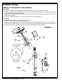
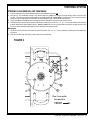
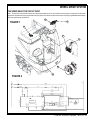
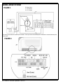
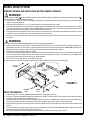
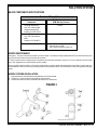
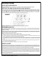
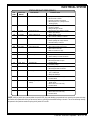
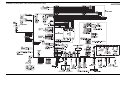
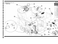
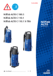
1
AquaRide™SE
BRX 700
SERVICE MANUAL
Advance MODEL 56314009
Nilfisk MODEL 56314019
5/03 revised 11/05 Form Number 56043089
TABLE OF CONTENTS
GENERAL INFORMATION ................................................................................................................................................... 2
SAFETY INSTRUCTIONS .................................................................................................................................................... 3
SPECIFICATIONS & MAINTENANCE ...............................................................................................................................4-6
PM CHECKLIST ................................................................................................................................................................7-8
KNOW YOUR MACHINE .................................................................................................................................................9-15
STEERING SYSTEM .....................................................................................................................................................16-17
STEERING COLUMN ASSEMBLY SHROUD REMOVAL ................................................................................................ 16
STEERING CHAIN REMOVAL AND TENSIONING ......................................................................................................... 17
WHEEL DRIVE SYSTEM...............................................................................................................................................18-27
GENERAL FUNCTIONAL OVERVIEW ............................................................................................................................. 18
DRIVE MOTOR SYSTEM CONTROLLER FUNCTION OVERVIEW ............................................................................... 18
WHEEL DRIVE TROUBLESHOOTING GUIDE ................................................................................................................ 21
STEERING SPINDLE & WHEEL DRIVE MOTOR ASSEMBLY REMOVAL ...................................................................... 22
DRIVE TIRE REMOVAL.................................................................................................................................................... 22
BRAKE ADJUSTMENT ..................................................................................................................................................... 24
DRIVE WHEEL BRAKE STRAP REPLACEMENT ........................................................................................................... 25
WHEEL DRIVE MOTOR CARBON BRUSH INSPECTION .............................................................................................. 25
POTENTIOMETER REMOVAL & TESTING ..................................................................................................................... 26
POTENTIOMETER INSTALLATION & ADJUSTMENT..................................................................................................... 27
DRIVE PEDAL NEUTRAL ADJUSTMENT & PEDAL REPLACEMENT ............................................................................ 27
SCRUB BRUSH SYSTEM .............................................................................................................................................28-33
FUNCTIONAL OVERVIEW ............................................................................................................................................... 28
SCRUB BRUSH SYSTEM TROUBLESHOOTING ........................................................................................................... 29
SCRUB DECK REMOVAL ................................................................................................................................................ 30
BRUSH DECK ACTUATOR REMOVAL ............................................................................................................................ 31
SCRUB BRUSH MOTOR(S) REMOVAL .......................................................................................................................... 32
SCRUB BRUSH BELT REPLACEMENT .......................................................................................................................... 32
SCRUB BRUSH SYSTEM MAINTENANCE ..................................................................................................................... 33
SCRUB BRUSH REMOVAL & INSTALLATION ................................................................................................................ 33
SOLUTION SYSTEM .....................................................................................................................................................34-39
FUNCTIONAL OVERVIEW ............................................................................................................................................... 34
OPERATIONAL OVERVIEW OF THE SOLUTION PUMP & SOLENOID FUNCTIONS ................................................... 35
TROUBLESHOOTING GUIDE ......................................................................................................................................... 36
MAJOR COMPONENTS SPECIFICATIONS .................................................................................................................... 37
NOZZLE MAINTENANCE................................................................................................................................................. 37
NOZZLE FIXTURE INSTALLATION ................................................................................................................................. 37
SOLUTION PUMP REMOVAL .......................................................................................................................................... 38
SOLUTION SOLENOID VALVE ASSEMBLY REMOVAL .................................................................................................. 38
SOLENOID VALVE DISASSEMBLY AND CLEANING ..................................................................................................... 39
RECOVERY SYSTEM ...................................................................................................................................................40-48
FUNCTIONAL OVERVIEW ............................................................................................................................................... 40
VACUUM MOTOR CIRCUIT OVERVIEW ........................................................................................................................ 41
VACUUM SYSTEM ELECTRICAL CIRCUIT OVERVIEW ................................................................................................ 42
TROUBLESHOOTING GUIDE ......................................................................................................................................... 43
VACUUM / RECOVERY SYSTEM SERVICE MAINTENANCE CHECKLIST ................................................................... 43
MAINTENANCE OF VACUUM FILTER AND FLOAT CAGE............................................................................................. 43
VACUUM MOTOR(S) REMOVAL ..................................................................................................................................... 45
RECOVERY TANK REMOVAL ......................................................................................................................................... 45
RECOVERY TANK BLADDER REMOVAL ....................................................................................................................... 46
RECOVERY TANK BLADDER INSTALLATION................................................................................................................ 46
VACUUM SHOES REMOVAL FOR MAINTENANCE ....................................................................................................... 48
72 - FORM NO. 56043089 / AquaRide™ / BRX 700
TABLE OF CONTENTS
ELECTRICAL SYSTEM .................................................................................................................................................49-76
BATTERIES / CHARGERS SPECIFICATIONS ................................................................................................................ 49
INSTALL THE BATTERIES ............................................................................................................................................... 49
DESCRIPTION OF THE BATTERY LOW VOLTAGE CUTOUT FEATURE ...................................................................... 50
DESCRIPTION OF THE BATTERY CONDITION INDICATORS ...................................................................................... 50
CHARGING THE BATTERIES .......................................................................................................................................... 50
BATTERY MAINTENANCE............................................................................................................................................... 51
BATTERY TESTING ......................................................................................................................................................... 51
ACTUATOR DRIVE NUT ADJUSTMENT ....................................................................................................................52-53
CURTIS SPEED CONTROL ........................................................................................................................................54-57
MAIN CONTROL BOARD FUNCTIONAL OVERVIEW..................................................................................................... 58
MAIN CONTROL BOARD TROUBLESHOOTING GUIDE ............................................................................................... 58
MAIN CONTROLLER ERROR CODES.......................................................................................................................58-59
MAIN CONTROLLER SERVICE TEST MODE ............................................................................................................60-63
MAIN CONTROL BOARD SPECIAL PROGRAM OPTIONS .......................................................................................64-69
ELECTRICAL COMPONENT LOCATION (before SN chart) ............................................................................................ 71
WIRING SCHEMATIC (before SN chart) .......................................................................................................................... 72
WIRING DIAGRAM (before SN chart) .............................................................................................................................. 73
WIRING DIAGRAM (after SN chart) ................................................................................................................................. 74
WIRING SCHEMATIC (after SN chart) ............................................................................................................................. 75
ELECTRICAL COMPONENT LOCATION (after SN chart) ............................................................................................... 76
Note: All references to right, left, front, or rear in this manual are as seen from the operator’s stand-point.
FORM NO. 56043089 / AquaRide™ / BRX 700 - 1
GENERAL INFORMATION
INTRODUCTION
This manual will help you get the most from your Nilfisk-Advance Rider Extractor. Read it thoroughly before servicing the machine.
Note: Bold numbers and letters in parentheses and underlined indicate an item illustrated on pages 9-10 i.e. (B).
This product is intended for commercial use only.
PARTS AND SERVICE
Repairs, when required, should be performed by your Authorized Nilfisk-Advance Service Center, who employs factory trained service personnel,
and maintains an inventory of Nilfisk-Advance original replacement parts and accessories.
Call the NILFISK-ADVANCE DEALER named below for repair parts or service. Please specify the Model and Serial Number when discussing
your machine.
(Dealer, affix service sticker here.)
NAME PLATE
The Model Number and Serial Number of your machine are shown on the Nameplate on the machine. This information is needed when ordering
repair parts for the machine. Use the space below to note the Model Number and Serial Number of your machine for future reference.
MODEL NUMBER
SERIAL NUMBER
TRANSPORTING THE MACHINE
CAUTION!
Before transporting the machine on an open truck or trailer, make sure that . . .
•
•
•
The machine is tied down securely - see tie-down locations (26).
All access doors and covers are secured (tape and strap as necessary).
The machine parking brake is set.
TOWING
CAUTION!
If the machine must be towed or pushed, make sure the Key Switch (Main Power) (J) is in the OFF position and do not move the
machine faster than a normal walking pace (2-3 mph, 3-5kph) and for short distances only.
OTHER MANUALS AVAILABLE
The following manuals are available from the Nilfisk-Advance Literature Service Department, for your Rider Scrubber:
•
Parts List - Form Number
56042439
•
Operation Manual - Form Number
56041540 (Danish, Norwegian, Swedish, Finnish)
56041541 (English, German, French, Netherlands)
56041542 (Spanish, Portuguese, Italian, Greek)
56041627 (English, Spanish)
2 - FORM NO. 56043089 / AquaRide™ / BRX 700
CAUTIONS AND WARNINGS
SYMBOLS
Nilfisk-Advance uses the symbols below to signal potentially dangerous conditions. Always read this information carefully and take the
necessary steps to protect personnel and property.
DANGER!
Is used to warn of immediate hazards that will cause severe personal injury or death.
WARNING!
Is used to call attention to a situation that could cause severe personal injury.
CAUTION!
Is used to call attention to a situation that could cause minor personal injury or damage to the machine or other property.
GENERAL SAFETY INSTRUCTIONS
Specific Cautions and Warnings are included to warn you of potential danger of machine damage or bodily harm.
•
•
•
•
•
•
•
•
•
•
•
•
•
•
•
•
•
•
WARNING!
This machine shall be used only by properly trained and authorized persons.
While on ramps or inclines, avoid sudden stops when loaded. Avoid abrupt sharp turns. Use low speed down hills. Clean only
while ascending (driving up) the ramp.
Keep sparks, flame and smoking materials away from batteries. Explosive gases are vented during normal operation.
Charging the batteries produces highly explosive hydrogen gas. Charge batteries only in well-ventilated areas, away from open
flame. Do not smoke while charging the batteries.
Remove all jewelry when working near electrical components.
Turn the key switch off (O) and disconnect the batteries before servicing electrical components.
Never work under a machine without safety blocks or stands to support the machine.
Do not dispense flammable cleaning agents, operate the machine on or near these agents, or operate in areas where flammable
liquids exist.
Do not clean this machine with a pressure washer.
CAUTION!
This machine is not approved for use on public paths or roads.
This machine is not suitable for picking up hazardous dust.
When operating this machine, ensure that third parties, particularly children, are not endangered.
Before performing any service function carefully read all instructions pertaining to that function.
Do not leave the machine unattended without first turning the key switch off (O), removing the key and applying the parking
brake.
Turn the key switch off (O) before changing the brushes, and before opening any access panels.
Take precautions to prevent hair, jewelry, or loose clothing from becoming caught in moving parts.
Use caution when moving this machine in below freezing temperature conditions. Any water in the solution or recovery tanks or
in the hose lines could freeze, causing damage to valves and fittings. Flush with windshield washer fluid.
The batteries must be removed from the machine before the machine is scrapped. The disposal of the batteries should be safely
done in accordance with your local environmental regulations.
SAVE THESE INSTRUCTIONS
FORM NO. 56043089 / AquaRide™ / BRX 700 - 3
SPECIFICATIONS
General Specifications
Machine Length
Machine Height
Machine Chassis Width w/out deck
Machine Width w/deck
Total Rated Machine Current (2) brush
Solution Tank Capacity
Recovery Bladder Capacity
Solution Flow Rate
(Maintenance)
(Restoration)
Sound power level
as per ISO 3744 (at operator)
Transport Speed (Fwd. Maximum)
Transport Speed (Rev. Maximum)
English (Metric)
60 in. (152cm)
53 in. (134.6cm)
29 in. (73.6cm)
31 in (78.7cm)
65 Amps
45 gal. (170l.)
25 gal. (95l.)
.55 GPM (2 liter/minute)
1.0 GPM (4 liter/minute)
73 dB(A)
4.2 MPH / 370 FPM (6.8km/hr)
2.9MPH / 259 FPM (4.7km/hr)
Wheel Drive Motor
Vacuum Motor (3 stage) (2 motors in parallel)
1.1 hp, 840 watt
.8 hp, 600 watt
Vacuum Water Lift (Sealed)
(Open Hole Adapter 1”)
78 in.
25 in.
Power Source (Batteries) STD
Battery Weight (each)
Battery Compartment Size
Height (Max.)
Width (Max.)
Length (Max.)
Calculated Battery Run Time
Battery Chargers – see Electrical System Battery Section
Scrub Brush Size
Diameter
Length
Scrub Brush Motor (1) AquaRide
Scrub Brush Motors (2) AquaRide SE/BRX 700
Scrub Brush Speed
Minimum Aisle Turn Width
Machine Net Weight*
Machine Gross Weight**
Cleaning Width (scrubbing path)
(6) 6V/238 @ 20 hour rate
66 lbs. (30kg)
14.5 in. (36.8cm)
22.25 in. (56.5cm)
25.25 in. (64.1cm)
3-3.5 hrs.
5.75 in. (14.6cm)
27 in. (68.6cm)
.75 HP / 560 watts
.75 HP / 560 watts
900 RPM
63 in. (160cm)
625 lbs. (283kg)
1,570 lbs. (712kg)
28 in. (71cm)
Coverage Rate Per Hour (Maintenance)
18,500 ft2 (1720 m2)
Coverage Rate Per Hour (Restoration)
8,000 ft2 (745 m2)
Approvals:
ETL and CE
*Net Weight: Standard machine without options, empty solution and recovery tanks, without removable scrub brushes and no batteries installed.
**Gross Weight: Standard machine without options, full solution tank and empty recovery tank, with removable scrub brushes and 305 AH
batteries.
***Listings for watts are maximum values.
4 - FORM NO. 56043089 / AquaRide™ / BRX 700
SPECIFICATIONS
FORM NO. 56043089 / AquaRide™ / BRX 700 - 5
MAINTENANCE
MAINTENANCE SCHEDULE
Maintenance intervals given are for average operating conditions. Machines used in severe operational environments may require service more
often.
MAINTENANCE ITEM
Daily
Weekly
Monthly
Yearly
Charge Batteries
•
Check/Clean Tanks & Hoses
•
Check/Clean/ Power Brush(s)
•
Check/Clean Vacuum Shoes
•
Check/Clean Vacuum Shut-Off Float
•
Check/Clean the vacuum motor foam filter(s)
•
Empty Debris Hopper
•
Clean Spray Nozzles
•
Check Each Battery Cell(s) Water Level
•
Inspect Brush Deck Skirts
•
Inspect and clean Solution Filter
•
Check Foot/ Parking Brake for Wear & Adjustment
•
Lubrication - Grease Fittings
•
* Check Carbon Brushes
•
Note: See the individual machine system sections for maintenance information.
* Have Nilfisk-Advance:
Check vacuum motor carbon brushes (Qty 2) once a year or after 300 operating hours.
Check brush motor carbon brushes (Qty 4) once a year or after 500 operating hours.
Note if the vacuum or brush motor brushes are 9.5mm (3/8 inches) or shorter, replace them.
Check wheel drive motor carbon brushes every 500 operating hours. The original length of each brush is 20mm (25/32 inches). Replace when
shorter than 9.5 mm (3/8 inches) to obtain the same motor efficiency as a new brush.
WARNING!
Turn the key switch off, set the parking brake and disconnect the battery before servicing the machine.
VACUUM SHOE MAINTENANCE
Check the vacuum shoes daily, they can be removed to aid in cleaning, see “Removing the Vacuum Shoes”. Remove any built-up string, hair or
carpet fibers.
SPRAY NOZZLE MAINTENANCE
Remove the spray nozzles once a week. Soak the nozzles overnight in a vinegar solution to remove chemical deposits.
LUBRICATING THE MACHINE
Once a month, pump a small amount of grease into each grease fitting on the machine until grease seeps out around the bearings.
Grease fitting locations are:
•
Steering Wheel Shaft Universal joint
Once a month, apply light machine oil to lubricate the:
•
Steering Chain
•
General Pivot Points For the Brush Deck Linkage
•
Scrub Deck Adjustment Knobs (4)
CLEANING THE VACUUM MOTOR FILTERS
Clean the vacuum motor filters daily with compressed air. For extremely dirty filters, wash with warm, soapy water and rinse thoroughly with clean
water. Allow the filters to dry completely before re-installing in the machine. MAINTENANCE NOTE: Keep a second set of filters on hand to use
while first set is drying.
POWER BRUSH MAINTENANCE
Check the brush(s) daily. Remove any built-up string, hair or carpet fibers. Check the bristle length. Have a service technician change the brush(s) when the brush
bristles are worn to 1 inch (25mm).
6 - FORM NO. 56043089 / AquaRide™ / BRX 700
Advance AquaRide SE
Nilfisk BRX 700
PM Checklist
Customer
A
B
C
D
L
M
W
Address
City
St
Model
Serial
Zip
Hours
OPERATIONAL INSPECTION ITEMS
Ref
OK
1
Steering
2
3
4
5
Drive Pedal Operation (check for Fwd/Rev Drive & any neutral creep)
Seat Safety Switch
Brakes (Service & Parking)
Drive System Performance (reference SVR Manual for Curtis drive programmer speed
changes)
Scrub System (Raise/Lower and test auto scrubbing functions Maintenance &
Restoration)
Vac Shoe Recovery System (Raise/Lower and auto lift in reverse function) (must be
programmed on)
Vacuum Performance (sealed water lift 78" and 1- inch open hole adapter 25 inches)
Solution Control (On/Off and flow volume Maintenance & Restoration)
Emergency Battery Disconnect Control Lever
Tilt Steering Mechanism and Seat
Optional Accessories (headlight, safety beacon, etc.)
Main Control Board Special Program Options (check all applicable program settings,
reference SVR Manual 560430898); Example, Fault Recall Mode, Etc.
Battery Charger Operation
6
7
8
9
10
11
12
13
14
Defect Codes
(circle)
A
A
Ref
Comments
Scrub Brushes, check for wear and rotate
Scrub Brush Motors
Scrub Brush Drive Belt, wear and tension
Scrub Brush Deck Actuator Motor
Brush Deck Idler Assembly Bearings
Scrub Deck Skirts
Solution Solenoid Valves (Maintenance & Restoration)
Solution Flow Control Valve
Solution Tank, Delivery Hoses & Filter
Vacuum Motor Carbon Brushes
Vacuum Motor Gaskets and Filters
Vacuum Float Ball & Cage Assembly
Recovery Tank Cover Gasket
Recovery Tank Drain Hose & Cap
Vacuum Pick-Up Tool & Hoses
Copyright 2003 Nilfisk-Advance.
Cylindrical
Carbon Brushes
W
sluggish
A
B
A
B
L
B
W
L
B
D
B D
D
Program as needed
D
OK
Defect Codes
(circle)
A
B
B
A
D
L
D
B
D
A
A
Does
Not
Work
W
W
W
D
M
B
C
B
C
Clean Filter Screen
Wear Limit 3/8”
W
W
L
D
L
W
W
L
C
Clean Float
C
Page 1 of 2
D
B
A
A
Flush
Back flush
D
A
C
A
Does
Not
Work
B
B
A
noisy
VISUAL INSPECTION ITEMS
15
16
17
18
19
20
21
22
23
24
25
26
27
28
29
Defect Codes
needs adjustment
binding
dirty or contaminated
damaged, bent or torn
leaks
missing
worn out
W
M
D
C
C
L
L
L
2/21/2001
FORM NO. 56043089 / AquaRide™ / BRX 700 - 7
VISUAL INSPECTION ITEMS (continued)
Ref
30
31
32
33
34
35
36
37
38
Comments
Battery Pack Condition (clean & water)
Front Drive Wheel Motor
Front Drive Tire (rim fastener torque)
Brake Band Lining Wear
Drive Pedal Linkage (neutral return)
Steering Chain (lubricate & tension)
Steering Column (knob & plunger spring) also Universal Joint
Rear Wheels
Sweep Debris Tray
OK
Load Test
Carbon Brushes
Tread Wear
Adjust Free Play
C
C
W
W
W
B
A
A
1/4” Deflection
Grease
Does
Not
Work
Defect Codes
(circle)
A
W
B
B
A
C
D
W
C
NOTE: For additional service information see service manual form number 56043089 and
operator manuals form number 56041540-56041542, 56041627 (English).
Defect Codes
A
B
needs adjustment
binding
WORK COMPLETED BY:
Service Technician Signature
C
D
L
dirty or contaminated
damaged, bent or torn
leaks
M missing
W worn out
ACKNOWLEDGED BY:
Date
Copyright 2003 Nilfisk-Advance.
8 - FORM NO. 56043089 / AquaRide™ / BRX 700
Customer Signature
Page 2 of 2
Date
2/21/2001
KNOW YOUR MACHINE
1
2
3
4
5
6
7
8
9
10
11
12
13
Recovery Tank Cover
Solution Tank Fill Cover
Operator’s Seat
Solution Tank Drain Hose
Steering Wheel Tilt Adjust Knob
Brake Pedal / Parking Brake
Solution Spray Jets
Drive Pedal, Directional/Speed
Vacuum Shoes
Drive and Steer Wheel
Wheel Drive Circuit Breaker
Control Circuit Circuit Breaker
Emergency Stop Switch / Battery Disconnect
14
15
16
17
18
19
20
21
22
23
24
25
26
Brush Deck
Rear Wheel
Battery Compartment (under seat)
Recovery Bladder Shutoff Float
Vacuum Motor Filter Housing
Recovery Bladder
Solution Filter
Recovery Bladder Drain Hose (rear of machine)
Machine Battery Connector
Control Panel
Debris Hopper
Solution Control Valve
Tie Down Locations (3)
FORM NO. 56043089 / AquaRide™ / BRX 700 - 9
CONTROL PANEL
A
B
C
D
E
F
G
H
I
J
K
Scrub OFF Indicator
Scrub OFF Switch
Maintenance Mode Indicator
Maintenance Mode Switch
Restoration Mode Indicator
Restoration Mode Switch
Hourmeter Display
Accessory Vacuum Indicator
Accessory Vacuum ON / OFF Switch
Key Switch / Main Power
Battery Condition Indicators
10 - FORM NO. 56043089 / AquaRide™ / BRX 700
K1
K2
K3
L
M
N
O
P
Q
R
Battery Condition Indicator (RED)
Battery Condition Indicator (YELLOW)
Battery Condition Indicator (GREEN)
Speed Select Switch (extract / transport)
Speed Select Indicator
Horn Switch
Vacuum Switch
Vacuum System Indicator
Solution System Indicator
Solution Switch
KNOW YOUR MACHINE
KNOW YOUR MACHINE DESCRIPTIONS:
Recovery Tank Cover (1) – Open to access Recovery Bladder for rinsing and/or cleaning Float Cage.
Solution Tank Fill Cover (2) – Open to fill the solution tank, only use low-sudsing liquid detergents designed for carpet extraction. The area around
the recovery bladder inside the recovery tank also holds solution. Total capacity is 40 gallons (151 Liters).
Operator’s Seat (3) – The machine operator sits here. The seat has a safety switch which prevents the machine from moving without an operator
in the seat.
Solution Tank Drain Hose (4) – Used to empty the solution tank.
Steering Wheel Tilt Adjust Knob (5) – Push down on this knob to adjust the Steering Wheel up or down.
Brake Pedal / Parking Brake (6) – Push down to stop machine. NEVER leave machine unattended without setting Parking Brake.
Solution Spray Jets (7) – Based upon which extraction mode is selected (maintenance or restoration) the solution will be sprayed out one of the
two different jets.
Drive Pedal, Directional / Speed (8) – The operator can make the machine go forward by pushing forward on it, or reverse by pulling backward on
it. The speed is variable depending on how far forward or backward the pedal is moved.
Vacuum Shoes (9) – Removes excess solution from carpet after cleaning.
Drive and Steer Wheel (10) – Wheel drive motor attached to this wheel to propel machine either forward or reverse. Also attached to Steering
Wheel for steering left or right.
Wheel Drive Circuit Breaker (11) – Provides overload protection to machine’s wheel drive motor, 45 Amp. If it trips, it will pop out. To reset, wait
one minute and press the button back in. If any breaker trips repeatedly, have the machine serviced.
Control Circuit Circuit Breaker (12) – Provides overload protection, 10 Amp. If it trips, it will pop out. To reset, wait one minute and press the
button back in. If any breaker trips repeatedly, have the machine serviced.
Emergency Stop / Battery Disconnect (13) – Push in on lever to disconnect batteries.
Brush deck (14) – Contains brush drive motor(s), brush(s) and solution spray jets.
Rear Wheel (15) – These two wheels along with the drive wheel, support the machine. Power and steering are supplied through the front drive
wheel.
Battery Compartment (16) – Batteries stored here, flip seat panel up to access.
Recovery Bladder Shutoff Float (17) – Shuts off vacuum when recovery bladder is full.
Vacuum Motors’ Filter Housing (18) – Location of Vacuum Motors air intake filters.
Waste Water Bladder (19) – Contains waste water as it is recovered from carpet. Total capacity of XX gallons (XX Liters).
Solution Filter (20) – Filters solution prior to entering pump and being sprayed on floor.
Recovery Drain Hose (21) – Used to empty the recovery bladder.
Machine Battery Connector (22) – Batteries plug into this connector, disconnect to charge batteries.
Control Panel (23) – Operator Controls found here, see “FUNCTIONAL DESCRIPTION OF CONTROL SWITCHES”.
Debris Hopper (24) – Collects debris that has been swept up by the machine. Empty and clean daily.
Solution Control Valve (25) – This valve should be fully open whenever extracting. Only close this valve before removing the solution filter to
prevent loss of solution.
FORM NO. 56043089 / AquaRide™ / BRX 700 - 11
KNOW YOUR MACHINE
FUNCTIONAL DESCRIPTION OF CONTROL SWITCHES:
The controls on the AquaRide™ / BRX 700 were designed with one touch operation in mind. For single pass extracting the user can simply depress
one switch and all systems on the machine will be ready to go.
For most single-pass extracting operations, the operator should only need to use the top three switches on the control panel. These are the Scrub
System Off, Maintenance Extract Mode, and Restoration Extract Mode switches. In the maintenance mode the solution spray is directed at the
scrub brush and the flow rate is reduced. The travel speed is limited to a medium speed. In the restoration mode the solution spray is directed at
the carpet ahead of the scrub brush and the flow is at maximum. The travel speed is limited to a slow speed.
Scrub System Off Switch (B) - Pressing this switch when the scrub system is active will cause the following to occur:
•
The scrub brush(s) will turn off and the scrub deck will raise to the up position
•
The solution flow will be stopped
•
The vacuum will shut off after a 10 second delay
•
The travel speed limit will return to the transport speed setting
Maintenance Extract Mode Switch (D) – If the scrub system is off, pressing this switch will cause the following to occur:
•
The scrub system will be enabled with the system configured for maintenance mode and the scrub deck will be lowered
•
The vacuum system will be enabled
•
The solution system will be enabled for maintenance mode
•
The travel speed will be limited to the maintenance mode speed setting
•
As soon as the throttle is moved from the neutral position the scrub brush(s) will start turning and the vacuum will turn on. If the direction is
forward the solution flow will start. If the direction is reverse the solution flow will be stopped. It is possible to program the control to automatically
raise the scrub deck in reverse. Refer to the Electrical System “Main Control Board Special Program Options” for details.
If the restoration mode is selected, pressing this switch will select the maintenance mode. If the maintenance mode is already selected, pressing
this switch will have no effect.
Restoration Extract Mode Switch (F) – If the scrub system is off, pressing this switch will cause the following to occur:
•
The scrub system will be enabled with the system configured for restoration mode and the scrub deck will be lowered
•
The vacuum system will be enabled
•
The solution system will be enabled for restoration mode
•
The travel speed will be limited to the restoration mode speed setting
•
As soon as the throttle is moved from the neutral position the scrub brush(s) will start turning and the vacuum will turn on. If the direction is
forward the solution flow will start. If the direction is reverse the solution flow will be stopped. It is possible to program the control to automatically
raise the scrub deck in reverse. Refer to the Electrical System “Main Control Board Special Program Options” for details.
If the maintenance mode is selected, pressing this switch will select the restoration mode. If the restoration mode is already selected, pressing this
switch will have no effect.
12 - FORM NO. 56043089 / AquaRide™ / BRX 700
KNOW YOUR MACHINE
FUNCTIONAL DESCRIPTION OF CONTROL SWITCHES (CONTINUED)
Accessory Vacuum ON/OFF Switch (I) - This switch is used when an external scrub wand is used. Pressing this switch will turn the vacuum on
continuously without regard to the throttle position. It will also enable the solution pump. If the scrub system was on it will be turned off. This includes
turning off the scrub brush(s) and raising the scrub deck and turning the solution flow to the scrub deck off. NOTE: Automatic shutoff of the vacuum
motor when the recovery bladder is full is disabled when the wand is enabled. The float in the recovery bladder will still prevent water from entering
the vacuum motor, but the motor will not shut off.
Key Switch / Main Power (J) – Main Power Switch.
Speed Select Switch (L) – This switch will allow the operator to select a faster travel speed while the scrub system is enabled thereby allowing
extracting at a higher rate of speed. This option can be disabled if desired. See the Electrical System “Main Control Board Special Program Options”
for details.
The transport, maintenance mode, and restoration mode speed limits can be programmed using a Curtis handheld programmer. Refer to the Electrical
System “Main Control Board Special Program Options” for details.
Horn Switch (N) – This switch will sound the horn as long as the switch is held.
The horn also functions as an automatic back-up alarm when the throttle is moved to the reverse position. The volume of the back-up alarm is
programmable. It can also be programmed to provide an annunciation feature that will sound whenever the throttle is in the forward position. See
the Electrical System “Main Control Board Special Program Options” for details.
Vacuum Switch (O) - This switch is used to turn the vacuum system on or off. Pressing this switch will alternate between on and off. The vacuum
will only turn on when the throttle is moved from the neutral position. It will remain on for 10 seconds after the throttle returns to neutral.
The vacuum also has an automatic shutoff feature that will turn the vacuum and scrub systems off if the recovery bladder becomes full. If this occurs,
the status display will show the word “FULL”. This feature can be disabled if desired. The shutoff threshold can also be adjusted if necessary. See
the Electrical System “Main Control Board Special Program Options” for details.
Solution Switch (R) - This switch is used to turn the solution system on or off. Pressing this switch when the scrub system has been activated will
alternate between on and off. The solution flow will only turn on when the throttle is moved from the neutral position in the forward direction. The
solution flow will turn off if the throttle returns to neutral or is moved to reverse.
FORM NO. 56043089 / AquaRide™ / BRX 700 - 13
KNOW YOUR MACHINE
DESCRIPTION OF INDICATORS ON THE CONTROL PANEL:
Scrub Off Indicator (A):
•
This indicator will be green if the scrub system is off and ready to be activated.
•
This indicator will be red if the scrub system has been turned off and the scrub deck is not up yet, or if the scrub deck is up and there is no
weight on the seat.
•
This indicator will flash red if there is a fault in the scrub system.
•
This indicator will be off if the scrub system has been activated.
Maintenance Mode Indicator (C):
•
This indicator will be green if the scrub system is on and the maintenance mode has been selected.
•
This indicator will be yellow if the maintenance mode has been selected but the throttle is in neutral.
•
This indicator will be off if the scrub system is off.
Restoration Mode Indicator (E):
•
This indicator will be green if the scrub system is on and the restoration mode has been selected.
•
This indicator will be yellow if the restoration mode has been selected but the throttle is in neutral.
•
This indicator will be off if the scrub system is off.
Hourmeter Display (G):
•
The hourmeter display will scroll the hourmeter information only if all of the systems are turned off and the Drive Pedal (8) has been in neutral
for at least ten seconds. Immediately once the key switch has been turned on the display will do a self-test (flash 8) to check all segments of
the display. Then the hourmeter information will also be displayed. The format for the display of the hours is as follows:
Example 123.4 hours
•
The display will indicate 1 followed by a short blank period
•
The display will indicate 2 followed by a short blank period
•
The display will indicate 3 followed by a short blank period
•
The display will indicate _ followed by a short blank period, this is used as a decimal point to indicate tenths of hours
•
The display will indicate 4 (tenths) followed by a long blank period
•
The display sequence will repeat
Accessory Vacuum Indicator (H):
•
This indicator will be green when the accessory function is on.
•
This indicator will be off if the accessory function is off.
Speed Selector Indicator (M):
•
This indicator will be green if a scrub mode has been selected and the faster scrub speed has been selected.
•
This indicator will be off if the faster scrub speed has not been selected.
Vacuum System Indicator (P):
•
This indicator will be green if the vacuum is on.
•
This indicator will flash green if the vacuum is in the ten second delayed-off condition.
•
This indicator will be yellow if the vacuum is enabled but the throttle is in neutral.
•
This indicator will flash yellow if there is a vacuum system fault.
•
This indicator will be off if the vacuum is off.
Solution System Indicator (Q):
•
This indicator will be green if the solution is on.
•
This indicator will be yellow if the solution is enabled but the throttle is in neutral.
•
This indicator will flash yellow if there is a solution system fault.
•
This indicator will be off if the solution is turned off.
Power Saving Sleep Function
The AquaRide / BRX 700 is equipped with a battery saving feature that will turn all of the machine systems and accessories off if the machine is left
in an idle state for a preset period of time. This sleep mode will only occur if the operator is not on the seat and the wand function is not in use. The
sleep mode is indicated by a short duration green flashing scrub system off indicator. The sleep function is automatically cancelled when the operator
sits on the seat or any of the control switches are pressed. The sleep delay period is adjustable from 10 to 90 minutes in 10 minute increments. The
default period is 10 minutes. It can also be disabled. Refer to the “Main Control Board Special Program Options” for changing the delay period.
14 - FORM NO. 56043089 / AquaRide™ / BRX 700
KNOW YOUR MACHINE
DESCRIPTION OF THE BATTERY CONDITION INDICATORS
The battery condition indicator (K) consists of three lights; a green (K3), a yellow (K2) and a red (K1). A fully charged battery pack will measure
above 37.6 volts with no load applied (2.09 volts per cell). The AquaRide™ / BRX 700 is equipped with a low voltage cutout feature that will turn the
scrub system off when the batteries are discharged to their minimum level. There are two different cutout levels to accommodate different battery
types. See the Electrical System “Main Control Board Special Program Options” for details. The voltage levels for the various indications are as
follows (the voltages shown represent the voltage under load):
Standard
Alternate
Green
34.00+
34.50+
Green & Yellow
33.00-33.99
34.00-34.49
Yellow
32.00-32.99
33.50-33.99
Yellow & Red
31.50-31.99
33.00-33.49
Red
31.00-31.49
32.50-32.99
Flashing Red/Cutoff
<31.00
<32.50
NOTE: Refer to service manual for selection of alternate cut-off level. Once the low voltage cutout level has been reached (flashing red indicator)
the batteries must be FULLY recharged (37.6V) to reset the battery condition indicator. The scrub system will not function until the indicator has
been reset.
DESCRIPTION OF ADDITIONAL HOURMETER / STATUS DISPLAY FUNCTIONS
The single character display in the upper right corner of the control panel is primarily used as a display for the hourmeter function. This display is
also used to display the following information depending upon which mode the control is in:
•
Error codes*
•
Display of control system default parameters*
•
Recovery tank FULL indicator*
If any of the systems on the machine are on or if the throttle is not in neutral, the display will be blank.
* NOTE: Reference (in the Electrical System manual section) the Main Control Board Troubleshooting Guide and the Control Board Special Program
Options sections. These sections will explain the machine error code descriptions and scrub system controller default parameter changes.
FORM NO. 56043089 / AquaRide™ / BRX 700 - 15
STEERING SYSTEM
STEERING COLUMN ASSEMBLY SHROUD REMOVAL
Upper Column
1
2
3
4
See Figure 1. Remove the center Wheel Adapter (A) from the steering wheel. Pry it off using a flat bladed screwdriver.
Remove the steering shaft retainer Hex Nut (B) (use a 3/4” socket wrench) and the two Washers (C & D). Next pull straight back on the steering
wheel to remove it from the metal Wheel Adapter (E).
Pull off the keyed metal wheel adapter from the steering shaft by using a two-jaw gear puller. With the wheel adapter off the loose Plastic Trim
Cup (F) can now be removed.
Remove the (4) Screws (G) securing the Column Shroud (H) and pull it off from the Column Base (I).
Lower Column
1
2
3
4
Tilt the steering wheel column as far back (close to the seat) as possible.
Remove the tilt column release Knob (J) (threaded) from its shaft.
Remove the (4) Screws (K) securing the Lower Shroud (L) and next pull the shroud far enough away from the column base to clear the tilt
release shaft through the shroud opening. Note: This will take some effort in prying the flexible plastic shroud around the movable tilt shaft.
Grip the shroud and pull up to completely release it from the steering column base and the foot brake assembly.
B
FIGURE 1
A
C
E
D
F
H
I
G
Remove plug
to access/grease
universal joint
L
View from back
side of panel (I)
J
K
FRONT
16 - FORM NO. 56043089 / AquaRide™ / BRX 700
STEERING SYSTEM
STEERING CHAIN REMOVAL AND TENSIONING
1
2
3
4
Turn the master key switch off and separate the battery pack emergency disconnect (13).
See Figure 2. From underneath the front of the machine loosen the (4) (M) Screws and push the lower steering column to the rear of the
machine. This is done to separate the Chain (N) from the Steer Sprocket (O). Service Note: Use a 5/8” socket with 3” extension to loosen
screws and also correctly position the large hole in the Steer Plate (P) in order to access the far back left screw.
Remove both Master Links (Q) that secure the chain to the Steer Plate (P) then remove the chain from the chassis.
Reassemble parts in reverse order and adjust chain tension so that there is about 3/16” – 1/4” (4.7 – 6.4mm) total deflection with moderate
pressure applied at the Mid-point (R) (as shown). Service Tip Note: Use a pry bar or shims between the chassis and steer column to help
secure the tension adjustment when tightening the (4) steering column mounting screws.
Maintenance
1
2
Inspect the chain for looseness and binding, re-tension the chain to 3/16”-1/4” (4.7 – 6.4mm) deflection by following the above adjustment
instructions.
Keep all of the steer chain links oiled to prevent excessive wear and binding.
FIGURE 2
M
O
R
Q
N
P
View from under
the machine
FRONT
FORM NO. 56043089 / AquaRide™ / BRX 700 - 17
WHEEL DRIVE SYSTEM
GENERAL FUNCTIONAL OVERVIEW
See Figures 1 & 2. An 840-watt 1.1 HP (permanent magnet) 36V motor/gear transmission combination wheel unit (M3) is used to propel all machines.
A Curtis model 1228 PMC solid state speed controller (A1) regulates (outputs) the variable speed Fwd/Rev wheel drive motor functions. The controller
unit is located to the left of the operator seat, behind the electrical access panel. The potentiometer R1 mounted to the operator’s foot pedal, inputs
to the (A1) controller the machine operator’s desired speed and directional demands.
DRIVE MOTOR SYSTEM CONTROLLER FUNCTION OVERVIEW
See Figure 2. To make the A1 speed controllers internal control circuits operational (power it up) the two switches S1 (key) and S2 (seat) must be
closed. This circuit inputs a positive (+) 36V to the A1 speed controls pin terminal #5 (*KSI). The F2 circuit breaker 45 Amp supplies the positive
high current (load) circuit input to the B+ controller terminal (Brn/Blk wire). The black wire from the negative (-) battery standoff supplies the battery
ground input to the B- terminal for both the control and load circuits.
See Figure 3. Depressing the foot pedal in either Fwd or Rev will move the 5K Ohm (R1) potentiometer shaft off its centered balanced (neutral)
setting of approximately 2500 Ohms. With this pot shaft movement the pot’s resistance value changes which generates a variable voltage signal
(0-5 volts). These control board voltage input signals are what energizes the Fwd & Rev directional relays, which selects the motor polarity and what
also manages switches the battery voltage On and Off (**PWM) that varies the motor speed.
*KSI: Key Switch Input
**PWM: Pulse Width Modulation, also called “chopping” is a technique that switches battery voltage to the motor ON and OFF very quickly, thereby
controlling the speed of the motor.
DRIVE MODE SELECTION OPERATION OVERVIEW
The following is a list of the speed control parameters that can be adjusted using a Curtis hand held programmer:
There are four programmable speed limits on the AquaRide. These are transport speed, fast maintenance speed, maintnance/fast restore speed, and
restore speed. For the maintenance and restore modes, the fast speed is selected by pressing the speed select switch* on the control panel.
For reference purposes, the speed control parameters below are followed by a number from 1 to 4. These are used to indicate which parameters
apply to which operating mode of the machine.
(1) Transport mode [fastest] (scrub system off)
(2) Fast Maintenance Mode (maintenance mode, speed select indicator = on)
(3) Maintenance/Fast Restore Mode (maintenace mode, speed select indicator = off OR restore mode, speed select indicator = on)
(4) Restore Mode [slowest] (restore mode, speed select indicator = off)
Value
Curtis Display Callout
3.0 sec
ACCEL MAX SPEED
3.0 sec
ACCEL MIN SPEED
3.0 sec
REVERSE ACCEL MAX
3.0 sec
REVERSE ACCEL MIN
100%
40%
M1 MAX SPEED
M2 MAX SPEED
24%
M1 MIN SPEED
17%
70%
30%
24%
OFF
M2 MIN SPEED
M1 REVERSE MAX SPEED
M2 REVERSE MAX SPEED
REVERSE MIN SPEED
THROTTLE AUTOCAL
TABLE #1
Description
Acceleration rate [time to go from stop to maximum speed
in seconds
Acceleration rate [time to go from stop to maximum speed
in seconds]
Reverse acceleration rate [time to go from stop to
maximum speed in seconds]
Reverse acceleration rate [time to go from stop to
maximum speed in seconds]
Transport speed maximum limit [% of full throttle]
Fast maintenance mode speed limit [% of full throttle]
Maintenance/fast restore mode speed limit [% of full
throttle]
Restore mode speed limit [% of full throttle]
Reverse speed maximum limit [% of full throttle]
Reverse speed maximum limit [% of full throttle]
Reverse speed maximum limit [% of full throttle]
Used for calibration of the throttle assembly
Factory
Programmed
Values
Approximate
Travel Speed
1, 2
3, 4
1, 2
3, 4
1
2
4.2 MPH
1.4 MPH
3
.8 MPH
4
1
2
3, 4
.5 MPH
*Speed Select Switch: This switch will allow the operator to select a faster travel speed while the scrub system is enabled thereby allowing extracting
at a higher rate of speed. The speed select indicator will be green if a scrub mode has been selected and the faster scrub speed has been selected.
It will be off otherwise.
18 - FORM NO. 56043089 / AquaRide™ / BRX 700
WHEEL DRIVE SYSTEM
THE SPEED SELECTOR CIRCUIT INPUT
Note: The maximum and minimum machine drive wheel speed setting for the four drive modes can be changed by using the Curtis hand held
programmer. Reference the Curtis programmer instructions found in the electrical system manual section to change programmable speed settings
from their original factory specifications.
S1
FIGURE 1
E1
S2
A1
F2
M3
R1
FIGURE 2
+
BLK
F2
BRN/BLK
2
CIRCUIT BREAKER, 45 AMP
F3
1
2 BRN/YEL
CIRCUIT BREAKER, 8 AMP
S1
1
S2
BRN
2
1
SW
SPST KEY
ORN
2
SW, SEAT
1
F4
2
ORN
FUSE, 1 A.
BRN
BRN/YEL
ORN
ORN/BLU
J4-5
STATUS
J4-11
SEAT SW.
J4-10
FOR./REV.
J4-4
REV.
VIO
1
3
R1
POT. 5K OHM
BLK
PIN 4 -- POT. WIPER
PIN 13 -- POT. LO
A1
SPEED CONTROLLER
B+
PIN5 -- KSI
PIN 18 -- SPEED LIMIT
PIN 3 -- POT. HI
PIN 8 -- SLOW/FAST
J4-3
POT. IN
VIO
GRA
YEL
B-
BLK
M2
RED/GRN
M1
YEL/BLK
M3
M
MOTOR
WHEEL DRIVE
Amps = 23
BRN/WHT
YEL
2
POT. OUT J4-9
J3-6
B- 4
J 3 - 5 B- 3
J2-5
B- 2
J4-8
B- 1
I -- BRUSH
E1
CONTROL BOARD
I -- VAC
SPEED LIMIT
ACC
BLK
GND J2-9
PIN 6 -- BRAKE
PIN 16 - REV. ALARM
INTERFACE
HORN -
PIN9 -- STATUS
KEY SW. J 2 - 1 0
B+ 1
BLU/BLK
HORN +
J4-2
J2-8
THERMISTOR
SOLUTION
VACUUM
BRUSH
J4-1
J4-7
J2-6
RED/BLK
J2-7
RED
1
B+ 2
RED
FORM NO. 56043089 / AquaRide™ / BRX 700 - 19
WHEEL DRIVE SYSTEM
FIGURE 3
R1 Voltage Values
0 – 2.5V Reverse
2.5 – 5V Forward
This drawing shows additional controller input circuit detail. The R1 pot is shown in the neutral position. Resistance is measured between pot low
and pot wiper.
FIGURE 4
20 - FORM NO. 56043089 / AquaRide™ / BRX 700
WHEEL DRIVE SYSTEM
Low Current A1 Speed Control Pin Key Detail
Pin #
Wire Color
1
2
3
4
5
6
7
8
9
10
11
12
13
14
15
16
–
–
Vio
Gra
Orn
Red/Blk
–
Brn/Wht
Orn/Blu
–
–
–
Yel
–
–
Blu/Blk
17
18
–
Blk
Controller Pin Description & Function
Open not used
Open not used.
Throttle Pot R1 pot high input
Throttle Pot R1 pot wiper input
KSI (key switch input): Battery (+) powers up controller logic circuits.
Auxiliary Driver: Battery (-) output to main controller (E1) to turn on (activate) all auto scrub functions.
Open not used
Mode Select 1: Drive motor scrub speed input, battery (+) from the (E1) Main Controller.
Status Fault: Speed controller fault output to main control panel fault indicator light (accessory wand)
Open not used
Open not used
Open not used
Throttle Pot R1 pot low input
Open not used
Open not used
Rev/Alarm Driver output Battery (-) commands turns off solution, raises scrub deck & sounds back-up
alarm
Open not used
Speed limit pot input connection (reference Table 1)
Transport and Fast-Maintenance – tied to Pot HIGH
Maintenance, Fast-Restoration and Restoration – tied to Pot LOW
WHEEL DRIVE TROUBLESHOOTING GUIDE
Problem
• Wheel drive motor will not run in
forward and reverse.
• Wheel drive in one direction only, loss of either
forward or reverse.
• Hourmeter/status display shows an error
03 fault code.
Possible Cause
• Batteries need charging (low battery voltage, recharge
batteries)
• Wheel Drive Motor Circuit Breaker (F2) tripped (reset 45A circuit
breaker)
• Control Circuit Circuit Breaker (F4) tripped (reset circuit breaker)
• Parking Brake (6) set (release parking brake)
• Emergency Stop Switch (13) tripped (pull red knob to reset)
• Safety Switch (S2) in seat not closed (check seat switch)
• Defective Wheel Drive Motor (replace motor) *
• Defective Throttle Potentiometer (R1) (replace) *
• Test the Fwd & Rev (R1) wiring outputs (pins 3, 4 & 13) at the
speed control for an open. Repair wiring or replace the R1
throttle pot.
• Controller can’t change electrical polarity to wheel motor
replace the (A1) speed control.
• Speed controller has sensed an operation error code fault.
(see the Status LED Fault Codes (Table 2) in the Electrical
System)
* = See Curtis Speed Control Troubleshooting Section.
FORM NO. 56043089 / AquaRide™ / BRX 700 - 21
WHEEL DRIVE SYSTEM
STEERING SPINDLE AND WHEEL DRIVE MOTOR ASSEMBLY REMOVAL
WARNING!
Turn the main key switch (J) to the off position and disconnect the battery pack by pushing in the emergency disconnect lever (13).
Next block both rear wheels so machine can’t roll.
1
2
3
4
5
See Figures 6 & 7. Remove the brake foot pedal (A) secured by the (2) screws (D) that fasten the pedal mount bracket to the chassis allowing
access to the spindle retainer nut.
Pull out the brake rod (E) and use a 1-7/16” socket to remove the large spindle nut (F) from its shaft.
From underneath the front of the machine loosen the (4) (G) screws and push the lower steering column to the rear of the machine. This is done
to separate the chain (H) from the steer sprocket (I). Service Note: Use a 5/8” socket with 3” extension to remove screws and also correctly
position the large hole in the steer plate (J) in order to access the far back left screw.
On the right side of the drive motor remove the motor wiring cover and observe the (2) wires (red/green & yellow/black) attached to the motor
terminal connections for reassembling. Then remove the wires using a 13mm wrench.
Remove the (1) socket head cap screw (use a 3mm hex wrench) that retains the motor wiring harness P-clamp, then pull wiring to the rear of
the machine.
WARNING!
Never work under machine without safety stands or blocking to support the machine.
6
Safely jack up or lift the front of the machine to a height of approximately 16 inches (41 cm) to remove the wheel motor spindle assembly. Place
wood blocking under both front frame legs to support machine when removing the wheel /spindle assembly. Service Note: Be careful not to
damage the threads and bearing surfaces when guiding the spindle shaft down through the frame opening.
7 Inspect bearings and shaft seal and replace as needed.
8 To remove the steer spindle weldment (K) you must remove the steer plate (J) (with splash fender) held by (4) (L) flat head socket screws (use
a 5 mm hex wrench) then separate the brake return spring and lay these removed parts to the side. Next remove the (4) item (M) flat head
socket screws (55mm length) then finish removing the spindle weldment.
9 See the “Drive Tire Removal” section for further disassembly steps.
10 Re-assemble in reverse order and tighten the spindle shaft nut (F) to 20ft/lbs (27 Nm) to eliminate any bearing play.
FRONT
Radius
Radius
FIGURE 5
DRIVE TIRE REMOVAL
1
2
3
4
5
6
Red/Grn
W ire
Yel/Blk
W ire
Follow the steps 1-8 in the “Steer Spindle and Wheel Drive Motor Assembly Removal” section.
See Figure 6. Remove the Retaining Ring (O) from the brake Pivot Pin (N). Then slide the pin out of the brake lever and support mount being
careful not to lose the washer which goes between them.
Carefully separate (tap off) the motor end bell housing (P) from the main motor case. Service Tip: To remove the housing use a brass drift or
piece of hard wood and strike the end bell edge evenly at points 120 degrees apart to slowly work it from the motor bearing.
Using a 5mm hex key wrench remove the (8) socket cap screws (Q) that secure the drive tire (R) to the motor drive hub and complete the tire
removal.
Install a new drive tire and tighten (torque) the (8) socket cap screws (Q) to 12 Ft/Lbs (16.2 N/M). Service Tip: Apply a small amount of Loctite
242 to all the cap screws to prevent the fasteners from backing out.
Re-assemble in reverse order following all the steps outlined in the steer spindle and drive motor removal section.
22 - FORM NO. 56043089 / AquaRide™ / BRX 700
WHEEL DRIVE SYSTEM
FIGURE 6
A
D
F
G
H
I
L
J
FRONT
E
M
K
O
R
P
Q
N
FORM NO. 56043089 / AquaRide™ / BRX 700 - 23
WHEEL DRIVE SYSTEM
BRAKE ADJUSTMENT
1
2
3
4
5
See Figure 7. Adjust the (E) brake rod’s length to eliminate any foot pedal free play (space between the pedal and rod end) when the pedal is
at rest (not being engaged).
The rod length can be changed by loosening the jam nut (S) and threading the adjustment screw (T) In or Out.
To access the brake rod remove the front pedal mounting hardware items (B & C), then swing (pivot) the pedal backwards out of the way.
Use a 3/8” wrench and 1/8” hex key wrench to both loosen and tighten the rods adjustable hardware.
Note: Also check the brake bands brake lining for wear when excessive pedal travel can not be eliminated through adjustments. Service by
replacing worn brake band and readjust and test for proper brake operation.
FIGURE 7
24 - FORM NO. 56043089 / AquaRide™ / BRX 700
WHEEL DRIVE SYSTEM
DRIVE WHEEL BRAKE STRAP REPLACEMENT
WARNING!
Turn the key switch to the off position and then disconnect the battery pack by activating the emergency stop switch/battery disconnect
lever (13).
1
2
3
4
See Figure 8. Remove from the brake band (U) the front lower outside retainer ring (V) (external type). Service Tip: Use retaining pliers (tip
size .038 inches/1 mm) to prevent damage when removing all retainer rings. Then drive out the pin (W) from the brake band end.
Remove the socket head cap screw (X) (use a 6mm hex key wrench) that fastens the left side brake lever to the support mount (Y). Next
separate the brake lever from the mount bracket and pull it down to access the back retaining ring and remove it at this time.
Remove the second mount pin then carefully expand the brake band enough to clear the drive wheel brake drum and remove from the
machine.
To install the brake band follow the above steps in reverse order. See the “Brake Adjustment” section in this manual and adjust the brake pedal
free play and test the brake system for proper operation.
CAUTION!
Test-drive the machine and check for positive brake pedal and parking brake functions.
WHEEL DRIVE MOTOR CARBON BRUSH INSPECTION (500 HOURS)
•
•
See Figure 8. There are (6) carbon brush assemblies, (4) of them are located equally spaced on the outside diameter of motor end bell cover.
Remove the inspection caps (Z) by carefully twisting the cap a 1/8 of a turn counterclockwise. The other (2) brushes are located behind the
motor wiring terminal cover (AA). Remove the black cover and terminal mounting hardware. Note: The (4) motor commutator brushes are
secured with two slotted screws.
A new carbon brush measures 20mm (.780 inches) in length. Replace the brushes when worn to a length less than 9.5mm (.375 inches).
FIGURE 8
FORM NO. 56043089 / AquaRide™ / BRX 700 - 25
WHEEL DRIVE SYSTEM
POTENTIOMETER REMOVAL AND TESTING
WARNING!
Disconnect the machine’s battery pack connector (13) before servicing.
Potentiometer Removal
1
2
3
4
See Figure 9. Remove the (5) Screws (AB) securing the drive pedal mount assembly to the chassis then carefully lift the pedal assembly up
and lay it on its side.
Observe the (3) wires connected to the Drive Pedal Potentiometer (pot) (AC) and also the single GRN/YEL throttle ground wire (AD), note the
proper wire colors and their terminal connections for re-assembly. Then disconnect wiring and remove the pedal mount assembly from the
machine.
Remove the Link Rod (AE) from the Pedal (AF). Note: Be careful not to lose the link rod mounting hardware items (AG).
Loosen the Nut (AH) and Screw (AI) at the drive pedal Throttle Lever (AJ). Then pry the lever off from the end of the item (AC) potentiometer
shaft. Next remove the pot from the Mount Housing (AK).
Testing the Potentiometer
Note: The pot doesn’t have to be removed from the housing to test.
1 Test the potentiometer using an Ohmmeter (the pot specification is 5K Ohms).
2 Connect the meter leads to each of the outside connections on the potentiometer. The meter should read approximately 5000 Ohms (plus or
minus 500 Ohms).
3 Next, move one of the test leads to the middle connection and turn the stem in both directions. The range of the readings should be approximately
0-5000 Ohms or 5000-0 Ohms increasing and decreasing through its full range.
4 If you do not get these readings replace the potentiometer.
FIGURE 9
26 - FORM NO. 56043089 / AquaRide™ / BRX 700
WHEEL DRIVE SYSTEM
POTENTIOMETER INSTALLATION AND ADJUSTMENT
WARNING!
The adjustment of the potentiometer is to set the drive pedal for a neutral drive motor operation. If the pot is not adjusted properly, the machine will
creep in either FWD or REV.
1 See Figure 9. Install the pot into the Mount Housing (AK) and tighten the attachment nut.
2 Connect together loosely both the Link Rod (AE) to the Pedal (AF), and the Throttle Lever (AJ) to the potentiometer input shaft. Then tighten
only the Link Rod (AE) pedal mounting Hardware (AG). Note: Check the movement of the Foot Pedal (AF) it must move freely in both Fwd and
Rev.
3 See Figure 9 inset. Attach test leads from a volt/ohm meter (set meter on 0x100 scale) to the YEL and VIO wire connection points on the
potentiometer to check it’s total resistance (example 4800 Ohms).
4 Next connect the ohmmeter test leads to the GRA and VIO potentiometer connection points. Then using a small screwdriver, turn the shaft end
on the pot to half the total resistance previously measured. Example: 4800 Ohms divided by 2 = 2400 Ohms. Then without turning the shaft,
tighten the Screw (AI) and Nut (AH) to secure the setting at the Throttle Lever (AJ).
5 Follow steps 1-2 in reverse order (see Potentiometer Removal steps) to finish the installation. Then test-drive the machine for proper speed and
FWD/REV directional control.
DRIVE PEDAL NEUTRAL ADJUSTMENT & PEDAL REPLACEMENT
If the drive pedal has been removed or replaced, the neutral position for the pedal will have to be set. Follow the steps below to accomplish this.
WARNING!
Disconnect the machine’s battery pack connector (13) before servicing.
•
Note: See Figures 9 & 10. Before making any adjustments, inspect the Torsion Spring (AL) for defects and the correct positions of both spring
ends (repair or replace).
To Adjust Pedal Spring
1 Loosen the Screw (AM) & Nut (AN), the screw with bushing is positioned between both Fwd & Rev torsion spring ends. Its placement controls
the needed pre-load pressure to eliminate excessive pedal free-play and a balanced spring rate to return the pedal to a centered (neutral)
position.
2 Push the screw back into the pedal frame slot to increase spring tension and eliminate pedal free play. Then tighten the screw & nut being careful
not to pull on the linkage connection to the pot shaft and disturb (move) its neutral setting.
To Replace Pedal or Spring
3 Position the torsion spring ends (A & B) as shown. This is with the Bushing (AO) and Screw (AM) not installed.
4 Place the bushing inside the pedal channel pilot it into position using a scratch awl or a pin punch.
5 Then pivot (press) the pedal and insert the screw from the opposite side pushing the guide tool out.
6 Use a screwdriver to tap and pry the bushing back in the pedal slot to increase spring tension
7 Work the bushing back & forth on both sides of the pedal to obtain equal spacing. Then tighten the screw and nut.
8 A correctly adjusted drive pedal will have minimal amount of free-play when selecting a drive direction.
9 Reconnect the batteries and test the machine to make sure it does not “creep” forward or reverse when the pedal returns to neutral.
10 Service Tip: Also confirm the Hourmeter/Status Display (G) is free of the error code 03 (drive system fault). If error 03 is shown the throttle is
not set properly for the potentiometer and or drive pedal neutral position. Check both again and readjust.
FIGURE 10
B
AO
A
Right Side View
Front View
FORM NO. 56043089 / AquaRide™ / BRX 700 - 27
SCRUB BRUSH SYSTEM
FUNCTIONAL OVERVIEW
• Cylindrical Brush System Overview
See Figure 6. The machines AquaRide SE and BRX 700 use two cylindrical brushes that counter rotate to sweep up light debris and scrub at the
same time. Each scrub brush is powered on opposing ends by 3/4 HP permanent magnet motors attached to separate poly-V belt/pulley drives.
• General Brush Overview
On all models the scrub deck platform is raised & lowered automatically by a vertically mounted electric lift actuator motor (M1). The operation of
the machine’s scrub functions are activated when the operator selects (presses) either the scrub maintenance or restoration (mode) panel buttons.
The scrub brush pressure ranges (light through heavy) are programmable allowing the operator the choice to vary the scrubbing effort (pressure)
for numerous carpet cleaning requirements. Note: See the Main Control Board Special Program Options section in this manual for more detailed
operation and instructions to change scrub pressure settings.
See Figure 1. The machine’s main scrub system input and output operating functions are regulated (managed) by the combined membrane switch
display panel and main control board E1. The major scrub system functions are…
• Scrub Brush Motor Run Function
To turn On (energize) the K1 brush motor solenoid either the scrub pressure maintenance or restoration buttons (location E1 panel) must be pressed
and the (foot activated) drive pedal moved off its neutral position triggering an output from the R1 directional throttle potentiometer. These twooperator functions deliver the required E1 control board and A1 speed control circuit inputs.
Detailed Explanation of the scrub motor function
A closed E1 membrane panel switch input (either maintenance or restoration) enables the E1 microprocessor automatic functions for the brush
lift, brush solenoid, solution solenoid and vacuum solenoid. The next step is the movement of the foot pedal for the needed R1 throttle output to
the A1 speed controller, which causes either FWD or REV motor action. At the moment of R1 throttle input the A1 controller closes an internal coil
driver and outputs a POS. 36V signal from pin #6 (wire color Red/Blk) to the E1 J4-10 connection. This positive input signal causes the controller
to output a NEG. 36V signal from J2 pin #1 (wire Wht/Red) and completes the K1 negative solenoid coil pulling in the high current contactor making
the brush motor(s) turn on (run). Note: The positive K1 control circuit voltage is supplied by the E1 board’s J2 pin #8 wire (Wht/Brn).
• Scrub Brush Actuator Lift Motor Function
The control board outputs activate (raise and lower) the scrub-deck for installing, removing and controlling the scrub brushes’ selected pressure
limits (current load). The negative (-) brush motor wire is specially designed so that it has a known (specified) resistance value. As brush motor
current passes through the negative wire that is, in effect, a low value resistor, a small voltage drop is measured across it which is proportional to
the motor current. This current measurement shunt circuit is made up of two small diameter sense wires (J4-12 Yel/Vio & J4-8 Blk) and are the
inputs used by the control board to calculate the exact current level of the scrub brush motor(s). Any temperature change to the large (Neg.) motor
wire affects its resistance so the circuit temperature is sensed by a thermistor (*) built into the control board. This allows the controller to provide
a level of error correction for the temperature resistance changes. When the controller senses a current draw out of the desired range (selected
pressure limit) it automatically turns on the M1 actuator motor to raise or lower the scrub deck. This process is on-going in maintaining the operator’s
selected scrub motor current load (setting #) to sustain the desired brush working pressure.
• Low Voltage Cut-Out Function
The purpose of the low voltage cutout function is to help prolong battery life. The main control board E1 is programmed to monitor the machine’s
battery pack voltage to prevent over discharging of the batteries. The brush motors, brush lift actuator and solution solenoid valve will turn OFF
automatically and cease to function when the batteries are discharged to the selected cutout level. The cutout level is adjustable between two
settings. The standard battery type (wet cell) is 31.5 volts (1.75 volts per cell) and maintenance free battery (gel) is 33 volts (1.83 volts per cell).
Note: See the Electrical System for instruction in selecting (setting) the two different thresholds.
* Thermistor: A special semiconductor resistor whose resistance value varies with temperature.
Note: See the “Know Your Machine” section in this manual for a complete explanation for all scrub system operational modes.
28 - FORM NO. 56043089 / AquaRide™ / BRX 700
SCRUB BRUSH SYSTEM
SCRUB BRUSH SYSTEM TROUBLESHOOTING
On all models the scrub system’s major electrical components are monitored by the main controller (E1) to detect any system function failures
(error codes). The system components covered are the brush motor(s) (M7 & M8), brush solenoid (K1) and brush lift actuator motor (M1). Detected
error codes from the main controller are displayed on the hour meter LED display (G) as they occur. Note: Reference the Main Control Board
Troubleshooting Guide in the Electrical System of this manual for specific fault descriptions and service repair actions.
BRN
K1
1
W HT/RED
K1
M OTOR, BRUSH
+
Amps = 22
RED
W HT/BRN
K2
L2
L1
ACC
J2-8
W HT/BRN
J2-6
J2-7
BRN/YEL
BRN/YEL
B+ 1
B+ 2
F3
M OTOR, BRUSH
M8
Amps = 22
+
BLU
BLK
2
KEY SW. J2-10
RED/W HT
RED
CONTACTOR , BRUSH Amps = .33
J3-1
ORN/BLK
RED
CONTACT N.O.
POT. IN
E1
CONTROL BOARD
J2-1 BRUSH
J3-4
S1
W HT/RED
BRN/W HT
J4-2 SPEED LIM IT
INTERFACE
I -- BRUSH
THERM ISTOR
J4-12
M 1 BRUSH LIFT
ACTUATOR
Amps = 3
+ M
YEL/VIO
F2
M
M7
A1
SPEED CONTROLLER
PIN 13 -- POT. LO
VIO
J4-3
1
YEL
J4-9
POT. OUT
J2-9
J4-5
STATUS
J4-11
SEAT SW.
J4-10
FOR./REV.
J4-4
REV.
GND
R1
POT. 5K OHM
BLK
3
BLU/BLK
RED/BLK
ORN/BLU
S2
ORN
2
BRN
J3-6
B- 4
J3-5
B- 3
J2-5
B- 2
J4-8
B- 1
F4
VIO
GRA
YEL
PIN 4 -- POT. W IPER
PIN 18 -- SPEED LIM IT
PIN 3 -- POT. HI
PIN 6 -- BRAKE
PIN 16 - REV. ALARM
RED
M
M1
M2
BPIN5 -- KSI
PIN9 -- STATUS
ORN
BLU
B+
PIN 8 -- SLOW /FAST
ORN
BRN/W HT
BRN/BLK
YEL/VIO
BLK
BLK
To W heel Drive M otor
BLK
BLK
FIGURE 1
FORM NO. 56043089 / AquaRide™ / BRX 700 - 29
SCRUB BRUSH SYSTEM
SCRUB DECK REMOVAL
1
2
See Figure 2. Pull off the two vacuum recovery Hoses (A) from the Vacuum Shoes (B).
Remove both vacuum pickup shoes by removing the two black Knobs (C) then lift up and pull out the retainer Bars (D) to separate them from
the scrub deck pins. Next pull back the pickup shoe from the deck bearing mounts to complete their removal.
3 Remove the sweep debris Hopper (E) from the scrub deck.
4 Lower the scrub deck with the brush(s) installed. Attention: Don’t turn the key switch off until after disconnecting the battery pack by pushing
in (activating) the Battery Disconnect (13). This procedure is done to prevent the scrub deck from automatically raising when the key is turned
off.
5 Remove the wing Nut (F) that secures the solution nozzle tree Assembly (G) to the scrub deck then pull the assembly with hoses to the side.
6 Unplug the brush motor wiring Harness (H) (under left side of machine).
7 Remove the lower hitch Pin (I) that secures the brush deck lift actuator to the scrub deck.
8 Remove the two Hitch Pins (J) that attach the scrub deck to the machine chassis linkage arm weldment.
9 From the right side of the machine swing the brush deck actuator housing forward to clear the deck mount bracket. Then carefully maneuver
the deck out from under the machine to complete its removal. Service Note: It is important that the disconnected deck actuator motor is not
run. This precaution will prevent the actuator drive nut from being moved from its set specification.
10 To install the scrub deck follow the above steps in reverse order.
FIGURE 2
Set stop bolt so that
brush housing is
approximately .38"
above the floor (cyl).
A
C
C
J
D
H
B
E
FRONT
30 - FORM NO. 56043089 / AquaRide™ / BRX 700
I
G
F
SCRUB BRUSH SYSTEM
BRUSH DECK ACTUATOR REMOVAL
1
Lower the scrub deck with the scrub brushes installed. Don’t turn the key switch off until disconnecting the battery pack by using the emergency
disconnect lever (13). This procedure is done to prevent the scrub deck from automatically raising when the key is turned off.
2 See Figure 3. From underneath the machine remove the clevis Mount Pin (K) that secures the lower actuator housing to the scrub deck mount
bracket.
3 Disconnect the brush lift motor wire harness at the motor.
4 Remove the top actuator (inspection) Cover (L) held with (3) screws. Cover location operator’s compartment below front of seat.
5 Remove the Hairpin (M) then slide the upper Mount Pin (N) out from the chassis mount bracket.
6 Remove the complete actuator lift motor assembly from underneath the machine. Note: Do not turn or reposition the drive nut on the actuator
shaft, mark if needed.
7 Important: After removing the actuator motor and before replacing a new motor or drive nut the IN & OUT limit switches must be set (or checked)
to their correct dimensional specifications (see the electrical section for the Actuator Drive Nut Adjustment instructions).
8 To disassemble the Drive Nut (O) from the actuator shaft, remove the (2) Screws (P) and separate both Retainers (Q & R) from the Spring
Housing (S).
9 Remove the (4) spring housing retainer Screws (T) and slide the spring housing and (long) Compression Spring (U) from the actuator shaft.
Next spin the drive nut off the shaft and save the top (short) Compression Spring (V). Note: See the Actuator Drive Nut Adjustment section in
this manual to properly install a new drive nut.
10 After adjusting the drive nut follow steps 1-9 in reverse order to re-install the scrub deck lift motor in the machine.
Service Tip: Wrap a small amount of tape around the spring housing to prevent it from spinning out of adjustment.
Service Tip: Shown in the Electrical System is the actuator power cord adapter PN 56407502 and instructions for use. This tool can be used to
help position (raise or lower) the drive nut housing for ease in the actuator mounting pin installations. An additional method to control the output
to the brush lift actuator for installation and removal is to read the instructions in the Service Test Mode section for the special output control of the
Maintenance Mode Switch (D) (See Electrical System for steps to enter the Service Test Mode).
FIGURE 3
L
N
M
FRONT
V
O
U
K
T
P
Q
S
R
FORM NO. 56043089 / AquaRide™ / BRX 700 - 31
SCRUB BRUSH SYSTEM
SCRUB BRUSH MOTOR(S) REMOVAL
1
See Figure 4. Remove the Belt Guards (W) (4 screws per side). With an operator in the driver’s seat with the key switch ON and the maintenance
mode scrub function selected press the drive pedal to start the scrub brushes and observe which brush motor needs to be removed.
WARNING!
Disconnect the battery pack by activating the emergency stop switch/battery disconnect lever (13) before servicing.
3
4
5
Next loosen the scrub brush belt tension Hex screw in the center of the Belt Idler (X) (using 5/8” & 11/16” wrenches).
Remove the wiring at both the Pos. & Neg. brush motor terminal studs and note the correct wiring connections (for reinstallation). Then remove
the (3) Screws (Y) and lift the motor out from the scrub deck.
Reassemble in reverse order and adjust the belt tension to 3/4 - 7/8 inches (19-22 mm) as shown in Figure 5. Note: Install motors with wires
pointing to the rear towards the plastic motor wiring standoffs.
SCRUB BRUSH BELT REPLACEMENT
WARNING!
Disconnect the battery pack by activating the emergency stop switch/battery disconnect lever (13) before servicing.
1
2
3
4
See Figure 4. Remove the belt guard(s) (W) (4 screws each).
Important Service Tip: The left and right side drive belts are not the same lengths they must be ordered individually (P.N. 56407465, left side
& P.N. 56407466, right side). Note: Single brush machine uses P.N. 56407465.
Loosen the scrub brush belt tension hardware on the Belt Idler Pulley (X) (using a 5/8” & 11/16” wrench). Pull the idler wheel away from the
backside of the belt and roll the belt off both the motor and brush pulleys. Then inspect for wear and replace as needed.
Re-install the drive belt and tension the belt as shown in Figure 5. Then install the belt guard, reconnect the battery pack and test the scrub
system for proper operation.
CCW *
FIGURE 4
W
Y
CCW *
Z
Y
X
Right side
belt
X
FRONT
W
*Rotation of shaft from shaft end.
Z
32 - FORM NO. 56043089 / AquaRide™ / BRX 700
SCRUB BRUSH SYSTEM
SCRUB BRUSH SYSTEM MAINTENANCE
The scrubbing system must be serviced at regular intervals to
maintain good scrubbing performance. Follow the maintenance
steps listed below.
1
2
3
4
5
6
FIGURE 5
Rinse clean, built up debris from the debris hopper drain holes
(daily).
Remove any string wrapped around the scrub brush, drive hub
and idler hub (daily).
Clean spray nozzles attached to the front of the scrub deck
(weekly).
Clean built up dirt from the inside of the scrub brush housing
(weekly).
Remove both the scrub brushes and rotate, turn end for end
(weekly). See Scrub Brush Removal and Installation (Cyl)
section.
Inspect the scrub brush bristles for wear, the brushes should
be replaced when the bristle length is 1 inch (26 mm) or less
(monthly).
SCRUB BRUSH REMOVAL AND INSTALLATION
1
2
3
4
Make sure the key switch is off and disconnect the battery pack before servicing.
See Figure 4. Loosen the black knobs (one on each side) that secure the removable bearing idler support Plate (Z) to the brush housing, then
pull the plates down and out to remove. Grip the scrub brush and slide it out from the housing end.
To install the brush slide it into the housing, lift slightly, push and turn until it seats into the drive end assembly.
Re-install the idler end plate assemblies.
FIGURE 6
FORM NO. 56043089 / AquaRide™ / BRX 700 - 33
SOLUTION SYSTEM
FUNCTIONAL OVERVIEW
See Figure 1. Two molded plastic (polyethylene) tanks rear recovery and the main body structure store the machine’s extraction solution. Total
machine solution capacity is 45gallons (170 L). Plumbed into the solution shut off Valve (C) outlet is a serviceable spin off Filter Housing Assembly
(D) that keeps debris from entering the Solution Pump (E) and solenoid valves (L1 & L2). Also fitted between the storage tanks is a short flexible
Drain Hose (F) to drain both tanks for system maintenance.
The electrical circuit that turns on (energizes) the solenoid coils is activated through the combined operator panel buttons and main controller assembly
E1. Note: See the Know Your Machine section in this manual for a detailed explanation of the complete solution operation modes. The two electrical
solenoid valves L1 maintenance and L2 restoration control (start and stop) the two specific defined solution nozzle outputs. The pump’s flow volume
is directed through one or the other operator selected (turned on) solenoid valve by hoses to the two separate brush nozzles A & B. Nozzle (A)
directs the solution spray pattern onto the scrub brush when in the maintenance extraction mode (minimum flow). Nozzle (B) directs the solution in
front of the scrub brush when in the restoration mode (maximum flow).
FIGURE 1
34 - FORM NO. 56043089 / AquaRide™ / BRX 700
SOLUTION SYSTEM
OPERATIONAL OVERVIEW OF THE SOLUTION PUMP & SOLENOID FUNCTIONS
Solution Delivery in the Auto Mode
Starts with the operator turning on the main power key switch then selecting either the maintenance or restoration mode switch.
Positive (+) battery circuit inputs and outputs
Inputs:
A Solenoid circuit control coil (+) voltage input to control board E1 connector J2 pin #’s 6 & 7 (wire colors Brn/Yel).
A closed S1 key switch supplies (+) input voltage to the E1 terminal J2 pin #10 (wire Brn). This powers up (turns on) the control board’s processing
logic functions.
•
A closed S2 operator safety seat switch enables allows the starting of the entire automatic machine scrubbing system functions. Its E1 terminal
connection is J4 pin #11 (wire Orn).
Outputs:
•
A control board E1 battery (+) voltage output from the solenoid accessory terminal connection J2 pin #8 Wht/Brn wire.
•
•
Negative (-) battery circuit inputs and outputs
Inputs:
A main (-) battery ground input for the control board E1 terminal J4 pin#8 BLK wire. This supports the operation of the boards processing logic
functions.
•
Battery ground supply input for all the (control boards) negative output coil circuits. Its E1 terminal connection is J2 pin #5 (wire Blk).
Outputs:
•
A battery ground output from the E1 control board terminal connector J2 pin #3 wire Vio/Blk for the L1 solenoid or J2 pin #4 wire Wht/Grn for
the L2 solenoid. This controlled output turns on and off the L1 & L2 solenoid coils that stops and starts the solution flow through the valve body
selected. This occurs every time the throttle is moved off its neutral setting into forward.
Solution Delivery in the Accessory Mode
Starts with the operator only having to turn on the main power key switch.
•
Positive (+) battery circuit inputs and outputs
Inputs:
Accessory/solenoid circuit (+) voltage input to control board E1 connector J2 pin #’s 6 & 7 (wire colors Brn/Yel).
A closed S1 key switch supplies (+) input voltage to the E1 terminal J2 pin #10 (wire Brn). This powers up (turns on) the control board’s processing
logic functions.
Outputs:
•
A control board E1 battery (+) voltage output from solenoid accessory terminal connection J2 pin #8 Wht/Brn wire. This feeds the pump pressure
switch S3, which is built into the pump M4. The pressure switch is normally closed and will open when the head pressure reaches its cutout
limit of 100 PSI. When the operator depresses the accessory wand trigger valve the trapped solution pressure drops below 100 PSI and the
pump will run.
•
•
Negative (-) battery circuit inputs
FIGURE 2
+ BT1 _
RED
S2
BRN
BRN
ORN
WHT/BRN
L1
VIO/BLK
J2-10
SEAT SW. J4-11
J4-10
FOR./REV.
PIN 6 - BRAKE
BLK
POT. IN J4-3 VIO
E1
Control Board
Valve, Maint. Solenoid
L2 WHT/ORN
WHT/BRN
Valve, Restore Solenoid
GND J2-9
POT. OUT J4-9 YEL
2
ACC
RED/BLK
WHT/BRN
1
3
R1
POT. 5K OHM
J2-5
B- 2
J4-8 B- 1
J2-8
J2-3
SOLUTION
J2-4
Interface
WHT/BRN
F4
ORN
Seat Switch
KEY SW.
J2-7
Sw, Spst
Key
BLK
Battery, 36 Vdc
S1
BRN/YEL
B+ 1
F3
BRN/YEL
RED
J2-6
•
A main (-) battery ground input to the control board E1 terminal J4 pin #8 BLK wire. This completes the circuit support for the operation of the
board’s processing logic functions.
A direct battery ground input for completion of the M4 pump circuit
B+ 2
•
PIN 18 -- SPEED LIMIT
VIO
PIN 3 -- POT. HI
GRA
PIN 4 -- POT. WIPER
YEL PIN 13 -- POT. LO
A1
Speed Controller
BLK
NOTE: PRESSURE SWITCH IS
PART OF PUMP ASSEMBLY
1
S3
M4
2
M
BLK
Pump, Accessory
FORM NO. 56043089 / AquaRide™ / BRX 700 - 35
SOLUTION SYSTEM
TROUBLESHOOTING GUIDE
Mechanical / Electrical / Plumbing
Problem
Inadequate or no solution flow
Possible Cause
No solution in the tank
Main solution flow shut off valve arm is in the closed position
Clogged solution filter, hoses & solenoid valves
Defective solution solenoid coils (L1 & L2)
Solution system fault in the main controller E1*
*On all models the solution system’s electrical solution solenoids L1 & L2 (maintenance & restoration modes) are monitored by the main controller
E1 to detect any system function failures (error codes). Detected error codes from the main controller are displayed on the (G) hourmeter LED
operator panel display as they occur. Note: Reference the Main Control Board Troubleshooting Guide in the electrical system of this manual for
specific fault descriptions and service repair actions.
SOLUTION SYSTEM MAINTENANCE
• Solution Tank: See Figure 1. Weekly empty the solution tank; remove the solution Drain Hose (F) from its storage area (located underneath the
left side of chassis). Direct the hose to a designated “Disposal Site” and flush the tank with clean water.
• Solution Filter: Remove and clean the inline Solution Filter (D). To access the filter housing for removal, work underneath the middle front of
the solution tank see molded “FILTER ” callout. No tools are needed to remove the filter (hand tighten only). Service Tip: The manual solution
shut off arm must be placed in the full CLOSED position (located next to filter). This prevents loss of solution when servicing the filter strainer with
a partial or full tank.
36 - FORM NO. 56043089 / AquaRide™ / BRX 700
SOLUTION SYSTEM
MAJOR COMPONENTS SPECIFICATIONS
Nozzle and Pump Data
Components
Flow Rate
GPM / Working Pressure
Nozzle (A) “Maintenance”
Spec. .057” orifice diameter
Hardened Stainless Steel
Nozzle tip I.D. QSTK-SS-3.0
.55 GPM
Nozzle (B) “Restoration”
Spec. .091”orifice diameter
Brass
Nozzle tip I.D. QTKA-BR7.5
.98 GPM
Pump Specifications
Pressure relief switch opens at 100 PSI
Max. flow rate 1.6 GPM
Max. current 3A (average current 2.7A)
NOZZLE MAINTENANCE
See Figure 4. To inspect and clean both nozzles no tools are needed. First remove the Wing Nut (G) that secures the nozzle bracket (tree) and
pull it from the brush housing slots with the hoses still connected.
To remove a nozzle to clean or replace just grip the nozzle tip and at the same time press in and twist it a 1/4 turn to separate it from the nozzle
body. Note: Suggested once a week to inspect and clean nozzles.
Clean by soaking nozzles overnight in a full strength vinegar solution or properly diluted and handled meratic acid solution to remove build up of
chemical deposits. Note: Do not ream out (increase) the orifice by cleaning with a drill bit. As this will affect the nozzle working pressure and spray
pattern.
NOZZLE FIXTURE INSTALLATION
1
2
3
Apply small amount of thread sealant (Loctite #242-blue) to the fixture threads.
See Figure 3. Thread the Nozzle Fixtures (H) into each brass barb.
Position nozzle fixture as shown (nozzle fixture flat must be 90º to bracket arm).
FIGURE 3
FORM NO. 56043089 / AquaRide™ / BRX 700 - 37
SOLUTION SYSTEM
SOLUTION PUMP REMOVAL
CAUTION!
Disconnect the machine’s battery pack connector (13) before servicing machine.
1
2
3
4
See Figure 4. Drain the solution tank using the Drain Hose (F) or put the flow shutoff Valve (C) into its closed position to prevent the uncontrollable
solution loss.
Loosen the (3) Hose Clamps (I) and remove the hose ends from the solution Pump (J) inlet and outlet fittings.
Cut the pump wiring harness tie straps then disconnect the pump wiring connector.
Remove the (2) (K) Screws that secure the pump assembly to the chassis then pull the pump out from underneath the machine. Service Tip:
Use a long thin shaft #2 Phillips screwdriver to access the two pump mounting screws.
SOLUTION SOLENOID VALVE ASSEMBLY REMOVAL
1
2
See Figure 4. Put the solution flow shutoff Valve (C) into its closed position and the scrub deck in the down position then disconnect the battery
pack.
Block rear wheels to prevent machine from rolling then jack up the front of the machine 3-4 inches.
CAUTION!
Support machine with proper blocking for safety.
3
4
5
6
7
Cut the necessary wiring harness tie straps used on the Solenoid Valve Assembly (L) then separate the wiring connectors for each valve.
Remove the two (M) screws that secure the solenoid mount bracket to the chassis.
Remove the wing nut (G) that retains the nozzle tree (bracket) and pull it off from the deck.
Loosen the necessary hose clamps from the solenoid valve that needs service then pry the hoses off their fittings.
Remove the two screws that fasten the valve body to the mount bracket to complete its removal.
FIGURE 4
38 - FORM NO. 56043089 / AquaRide™ / BRX 700
SOLUTION SYSTEM
SOLENOID VALVE DISASSEMBLY AND CLEANING
Note: See Figure 5 for valve disassembly & cleaning.
Service Tip: To just clean the valve assembly of any trapped debris it isn’t necessary to completely remove it from the chassis mount bracket. Follow
the short cut steps listed.
1 Use a flat bladed screwdriver to hold the slot on the end of the Valve Spool (N) and remove the Nut (O). Next pull off the metal protective Cap
(P), Coil (Q) and Washers (R). Use the screwdriver again and turn out (remove) the valve spool and Piston (S) (be careful not to lose any
internal parts).
2 Thoroughly wash out all debris from the Valve Body Seat (T) then reassemble and test the solenoid for proper operation.
FIGURE 5
FORM NO. 56043089 / AquaRide™ / BRX 700 - 39
RECOVERY SYSTEM
FUNCTIONAL OVERVIEW
Vacuum / Recovery System General
To start the extraction wastewater is lifted out of the carpet pile by airflow created by two 3 stage 36V vacuum motors. See Figure 1. The wastewater
and air enter at the two vacuum pick-up tools through their small narrow shoe openings that contact the carpet surface. The narrow shape of the
shoe openings are designed to help speed up the airflow producing the needed suction to lift the waste water out of the carpet. Two smaller recovery
hoses are connected together and direct the high-speed air/water movement to one large hose connected to the tank inlet. At this point the air and
water enters the large flexible sealed recovery bladder, where the air slows down because of the increased (size) of the tank. With the decreased
air speed the heavier water falls to the bottom of the recovery bladder. Then at the same time the airflow continues through shutoff float, vacuum
motors and is exhausted out the bottom of the vacuum motor housing.
The vacuum system uses a shutoff float to prevent the tank from being overfilled and also stops any water from being sucked into the vacuum
motors. This shut-off function works when the float ball reaches its tank full level and the ball becomes seated in the float housing. This action then
causes a large restriction to the vacuum airflow and the main controller E1 senses a large electrical current load change (lower Amps) to the vacuum
motors. This lower than normal vac circuit current load change tells the main controller that the recovery tank is full. This automatically shuts off
the vacuum and scrub systems and displays “FULL” on the hourmeter/status display telling the operator that the recovery tank has become full.
FIGURE 1
Recovery
Tank Cover
Float Cage
& Ball
FRONT
Vacuum M otors
Cover Gasket
Vacuum Hose
Drain Hose
Recovery Bladder
Pickup Shoes
40 - FORM NO. 56043089 / AquaRide™ / BRX 700
RECOVERY SYSTEM
VACUUM MOTOR CIRCUIT OVERVIEW
There are two vacuum switch operator modes, Auto vacuum for machine transport extraction use and manual On/Off stationary optional accessory
uses. Note: see the Know Your Machine section in this manual for a detailed description of the vacuum operation modes.
Vacuum motor system function in the Auto Mode:
Starts with the operator turning on the main power key switch then selecting either the maintenance or restoration mode function switch.
Positive (+) battery circuit inputs and outputs
Inputs:
See Figure 2. A Solenoid circuit control coil (+) voltage input to control board E1 connector J2 pin #’s 6 & 7 (wire colors Brn/Yel). Note: This
input voltage supplies all the machine’s accessory and solenoid coil circuits (solution, vacuum, brush, headlight, warning beacon etc.).
•
A closed S1 key switch supplies (+) input voltage to the E1 terminal J2 pin #10 (wire Brn). This powers up (turns on) the control board’s processing
logic functions.
•
A closed S2 operator safety seat switch enables the starting of the entire automatic machine scrubbing system functions. Its E1 terminal
connection is J4 pin #11 (wire Orn).
Outputs:
•
A control board E1 battery (+) voltage output from the solenoid accessory terminal connection J2 pin #8 Wht/Brn wire completes the positive
voltage to the vacuum solenoid coil.
•
Negative (-) battery circuit inputs and outputs
Inputs:
A main (-) battery ground input for the control board E1 terminal J4 pin #8 wire Blk. This supports the operation of the board’s processing logic
functions with the above mentioned S1 (+) key switch input.
•
A battery ground input for all the (E1 boards) negative solenoid coil output circuits. Its E1 terminal connection is J2 pin #5 (wire Blk).
Outputs:
•
A battery ground output from the E1 control board terminal connector J2 pin #2 wire Gra/Blk. This control board output completes the K2 vacuum
solenoid coil circuit (Pos. & Neg.) and pulls in the vacuum solenoid load contact K2 making the vacuum motor(s) M5 & M6 run. This occurs
every time the throttle is moved off its neutral setting and the vacuum switch is on. Note: When the throttle is returned to neutral the vacuum
will remain on for 10 seconds and the indicator light will flash green.
•
FIGURE 2
+ BT1 Battery, 36 Vdc
RED
S1
1
BRN
K2
Contact N.o.
PIN5 -- KSI
J4-11
J2-5
B-2
J4-8 B-1
I -- VAC
BLK
A1
Speed Controller
BLK
BRN/RED
- GRA/BLK
Vacuum Solenoid Coil
RED
E1
Control Board
B-
W HT
M5
M
BLK
BLK
+
SEAT SW.
Thermistor
W HT
K2
ORN
BRN/RED
W HT/BRN
W HT/BRN
J2-2 VACUUM
ACC
F4
ORN
ORN
Interface
J2-8
2
Sw , Seat
J2-10
KEY SW.
B+ 2
S2
BRN
Sw , Spst
Key
J2-7
BRN/YEL
BRN/YEL
B+ 1
F3
J2-6
RED
BLK
M6
M otor, Vac
M
FORM NO. 56043089 / AquaRide™ / BRX 700 - 41
RECOVERY SYSTEM
VACUUM MOTOR CIRCUIT OVERVIEW (CONTINUED)
Vacuum motor system function in the Accessory On/Off Switch Mode:
Starts with the operator turning on the main power key switch then selecting the accessory mode function switch.
Both Positive (+) battery and Negative (-) battery circuit inputs and outputs are the same as above except as noted below:
•
The vacuum motors will run continuously without the (normal) machine auto mode interruptions. Examples: No foot pedal throttle inputs, no 10
sec. time delay shut-off, no auto full indicator display and system shut down, no operator in seat input.
42 - FORM NO. 56043089 / AquaRide™ / BRX 700
RECOVERY SYSTEM
TROUBLESHOOTING GUIDE
When extracting the operator sees little or no (below normal) waste recovery water entering the recovery tank bladder, the vacuum system is not
working properly. When a vacuum system performs poorly, it is usually because of one of the following problems:
Vacuum Leak(s) – Air flowing into the vacuum system past a bad gasket or leaky hose, damaged tank, or a leaky drain hose cap. A vacuum leak
below the water line will create turbulence in the recovery tank, causing water to enter the vacuum motor.
Restriction(s) – Anything that blocks the flow of air through the system. Restrictions may also be caused by built-up debris in the pick-up tools,
vacuum hoses, float cage or wherever the airflow is forced to make a sharp turn.
Both leaks and restrictions decrease the quantity of air flowing through the pick-up tools. The air that does go through the pick-up tools moves with
less pressure and volume, so it has less pick-up power.
Vacuum Electrical Components – The vacuum systems major electrical components are monitored by the main controller to detect any system
function failures (error codes). The system components covered are the vacuum motors and vacuum solenoid. Detected error codes from the
main controller are displayed on the hour meter LED display as they occur. Note: Reference the Main Control Board Troubleshooting Guide in the
Electrical System of this manual for specific fault descriptions and service repair actions.
VACUUM / RECOVERY SYSTEM SERVICE MAINTENANCE CHECKLIST
Whenever there is a vacuum problem, it’s best to check over the entire system. Use the checklist below as a guide, to thoroughly check the vacuum
system.
Clean built-up dirt from the inside of both vacuum pick-up (shoes) tools.
Inspect the vacuum motors duct (plenium housing) cover gaskets, clean foam air inlet filters and screens.
Inspect the hose between the pick-up tools and the recovery tank, rinse any built-up dirt from the hoses. Replace the hose(s) if it is
kinked or damaged.
Inspect and make sure the gaskets on the recovery tank covers are sealing and not damaged.
Inspect and clean the vacuum motor float cage, float ball and shut-off seat.
Make sure that the recovery tank drain hose cap seals airtight.
MAINTENANCE OF VACUUM FILTER AND FLOAT CAGE
See Figure 3. To inspect and clean the vacuum motor foam filter just lift open the tethered Vac Duct Cover (A). Remove the filter by pulling it out
from the housing opening. Clean the filter by vacuum or washing it out in warm water. Note: The filter must be completely dry before reinstalling.
To inspect the vacuum shut off float just open the right rear recovery tank cover to access the float cage assembly (back center in recovery tank).
The cage openings must be kept free of any debris that can restrict maximum airflow. To keep it clean, wipe off with a rag regularly or remove and
flush with water. The cage is a two piece design and can be snapped apart to separate. Note: Another method of accessing the cage float for
servicing is to remove the (6) (B) Screws and remove the vacuum duct housing (C) from the recovery tank top opening.
FORM NO. 56043089 / AquaRide™ / BRX 700 - 43
RECOVERY SYSTEM
FIGURE 3
44 - FORM NO. 56043089 / AquaRide™ / BRX 700
RECOVERY SYSTEM
VACUUM MOTOR(S) REMOVAL
1
2
3
See Figure 3. Remove the vacuum duct Cover (C) that is secured to the recovery tank by a qty of (6) Screws (B).
Separate the wiring harness from each motor and lift motor(s) out from their mounting cavity.
Inspect all the vacuum/recovery system Gaskets, (items E, F, G & H) also clean the vacuum motor(s) Foam Filters (I, J & K), Screens (L) and
Exhaust Hoses (M).
4 Inspect the carbon motor brushes, if less than 3/8” (10mm) in length replace.
* Service Note: The hinged Tank Cover (D) can easily be separated from the vacuum Duct Cover (C) by removing the slotted Pin (N) (by using a
flat bladed screwdriver).
RECOVERY TANK REMOVAL
1
2
3
4
5
6
7
Drain both the solution and recovery tanks by using the system drain hoses.
See Figure 3. Loosen the hose clamps for both the small and large solution Hoses (O) & (P) (location bottom backside of tank) then remove
the hoses from their tank fittings.
Separate the vacuum Hose (Q) from the Y-shaped vacuum system Hose Assembly (R) (located inside the right rear wheel).
Pull the solution system vent Hose (S) off from the barbed elbow connected to the recovery tank.
Swing open the operator seat platform (set the prop rod) and pull apart the vacuum motors’ harness connector (located left rear of battery
compartment).
Open the hinged recovery tank Cover (D) and grip the top inside edge of the tank bladder and pull straight up to complete the tank’s separation
from the machine’s solution tank/chassis assembly.
Next guide the tank off the rear of the machine supporting the tank on its left corner to prevent crushing of the vacuum hose, then lay it down
onto the floor. Note: There is some weight to the tank assembly. Be careful when lifting it off ask for an extra helper to assist.
FORM NO. 56043089 / AquaRide™ / BRX 700 - 45
RECOVERY SYSTEM
RECOVERY TANK BLADDER REMOVAL
1
2
3
4
5
6
7
8
Drain both the solution and recovery tanks by using system drain hoses.
See Figure 3. Remove the (6) screws the secure the combined recovery tank and vacuum motor Cover Assembly (C). Then pull-up the cover
and completely remove the cover assembly by carefully guiding the float cage through its tank opening.
Loosen the drain Hose Clamp (T) and pull the hose off the tank fitting, next pry the plastic hose bushing (U) off the tank fitting.
Remove from the tank fitting the item (V) conduit lock nut by striking the nuts notched lugs (CCW) with a flat bladed screwdriver. Also remove
and save the Washer (W) and sealing O-ring (X).
From the front side of the tank loosen the Hose Clamp (Y) and pry off the solution feed Hose (O) as shown. Next use a lock pliers and remove
(unthread) from the tank the Elbow Fitting (Z).
From outside of the tank push the bladder drain fitting through its mounting hole. Note: Observe that the bottom bladder drain fitting clears the
tank-mounting hole and reach down inside the bladder and pull it up enough to complete its removal from the tank-mounting hole.
Use a 7/16-inch wrench and Phillips screwdriver and remove the (5) (AA) Screws and (5) (AB) Nuts that secure the bladder support straps as
shown.
Pull the top metal bladder supports down from the tank mount opening then collapse the bladder and pull it up and out of the tank opening.
When replacing a new bladder it will be necessary to remove and save the metal supports.
Hole #
1
2
3
4
5
Hardware used
Scr, Flt Phil SS 1/4-20 x 2.00
Scr, Flt Phil SS 1/4-20 x 2.00
Scr, Flt Phil SS 1/4-20 x 2.25
Scr, Pan Phil SS 1/4-20 x 1.00
Scr, Pan Phil SS 1/4-20 x 2.25
Wsh, Flt SAE SS 1/4
Wsh, Flt SAE SS 1/4
Wsh, Flt SAE SS 1/4
Wsh, Flt SAE SS 1/4
Wsh, Flt SAE SS 1/4
Nut, Acorn SS 1/4-20 High Crown
Nut, Acorn SS 1/4-20 High Crown
Nut, Acorn SS 1/4-20 High Crown
Nut, Hex Nyl Loc SS 1/4-20
Nut, Acorn SS 1/4-20 High Crown
AA
#1
FIGURE 4
#5
AB
AA
#2
FRONT
#4
RECOVERY TANK BLADDER INSTALLATION
1
AA
#3
Mix a one-quart volume of water and soap solution in a small spray bottle then spray the insides of the recovery tank and the outside of the
bladder just before installing. This needs to be done to help the bladder slide easily when positioning it in place. Note: Do not use any siliconebased products that will be in contact with the bladder, damage to the bladder will result.
2 Install the special rope and pulling bar inside the bladder as shown. Service Tip: Figure 5 shows the dimensions for building the pulling tool
needed to install the drain fitting through the bottom tank mounting hole.
3 Next feed the end of the rope from the drain fitting of the bladder through the bottom of the tank hole to the outside.
4 Carefully push the bladder down into the recovery tank with the needed assistance of pulling on the rope.
5 Working through the tank drain outlet opening pull the rope and pry the bladder tube fitting down where it is partially visible.
6 Spray additional soap solution through drain hole and hold the rope firmly while prying down on the fitting using a screwdriver to keep the fitting
from pulling away from the tank hole (use caution to not damage the bladder).
7 Remove the screwdriver and quickly slide in a piece of a rounded end steel shafting (approximately 3/4” in Diameter and 18” in length, a large
auto mechanics breaker bar works well) into the drain opening.
8 Pull down on the rope and quickly pull up on the lever turning and drawing the drain tube into the tank hole opening. Next pull out from the top
bladder opening the drain tube pulling tool by its free rope end.
9 Reinstall all of the previously removed plumbing fittings, support straps, hardware and hoses. Service Tip: To easily install the plastic drain
hose Bushing (U) onto the aluminum drain tube drop the bushing into a small cup of warm water to soften.
10 Fill the solution tank and check for leaks.
46 - FORM NO. 56043089 / AquaRide™ / BRX 700
RECOVERY SYSTEM
FIGURE 5
FIGURE 6
FORM NO. 56043089 / AquaRide™ / BRX 700 - 47
RECOVERY SYSTEM
VACUUM SHOES REMOVAL FOR MAINTENANCE
1
2
3
4
With the Master Key Switch (J) off have the operator check and clean the vacuum shoes daily.
See Figure 7. Pull off the two vacuum recovery hoses from the vacuum shoe inlets, then loosen the two black Knobs (AC) and lift up and pull
out the Retainer Bars (AD) to separate them from the scrub deck pins.
Next pull back the pickup shoe from the deck support bearing mounts to complete their removal.
Rinse the shoe housings with warm water to remove any build up of string, hair or carpet fibers. Then reinstall shoes in reverse order of
removal.
FIGURE 7
48 - FORM NO. 56043089 / AquaRide™ / BRX 700
ELECTRICAL SYSTEM
BATTERY SPECIFICATIONS
- Use a combination of multiple 2-volt cell units (wired in series) to construct a 36 Volt DC battery pack system.
- Nilfisk-Advance recommended battery pack capacity is a 238 or 305 AH @ 20 Hour Rate deep cycle battery system (six 6V-batteries). Note: The
battery pack must fit the battery compartment size listed in Specifications.
BATTERY CHARGER SPECIFICATIONS
- Use a 36 Volt DC output charger matching the DC battery pack voltage and the input AC line voltage supply being used.
- Always when selecting a battery charger follow the recommendation of the battery supplier to match the proper charger DC output amperage to
the amp/hour rating batteries being installed. This will prevent the battery pack from being over or under charged.
- The recommended 238 AH battery should be matched to a 36V, 20 Amp charger.
- The recommended 305 AH battery should be matched to a 36V, 25 Amp charger.
INSTALL THE BATTERIES
WARNING!
Use extreme caution when working with batteries. Sulfuric acid in batteries can cause severe injury if allowed to contact the skin or
eyes. Explosive hydrogen gas is vented from inside the batteries through openings in the battery caps. This gas can be ignited by
any electrical arc, spark or flame.
When Servicing Batteries...
•
Remove all jewelry.
•
Do not smoke.
•
Wear chemical goggles, rubber gloves and a protective apron.
•
Work in a well-ventilated area.
•
Do not allow tools to touch more than one battery terminal at a time.
CAUTION!
Electrical components in this machine can be severely damaged if the batteries are not installed and connected properly. Batteries
should be installed by Nilfisk-Advance or by a qualified electrician.
1
FIGURE 1
Remove the batteries from their shipping crate and carefully inspect
them for cracks or other damage. If damage is evident, contact
the carrier that delivered them or the battery manufacturer to file a
damage claim.
2 Turn the Master Key Switch (J) OFF (O) and remove the key.
3 To access the battery compartment tip the operator’s seat forward
and set the prop rod. Remove the battery cables from inside the
battery compartment.
4 Your machine comes from the factory with enough battery cables
to install six (6 volt), 305 Amp hour batteries. Using two people
and an appropriate lifting strap, carefully lift* the batteries into the
compartment tray exactly as shown on machine decal (Figure 1).
5 The terminals on the battery cables are marked “+” for positive and “-“
for negative. Install the battery cables as shown, with the terminals
marked “+” on the positive battery terminals and the terminals marked
“-“ on the negative terminals. Position the cables so the battery caps
can be easily removed for battery service.
6 Carefully tighten the nut in each battery terminal until the terminal will
not turn on the battery post. Then tighten the nut half an additional
turn. Do not over-tighten the terminals, or they will be very difficult
to remove for future service.
7 Coat the terminals and posts with spray-on battery terminal coating
(available at most auto parts stores).
8 Put one of the black rubber boots over each of the terminals and retain with supplied tie straps.
9 Connect the battery pack connector to the Machine Battery Connector (22) and close the operator’s seat platform.
*Note: Removal of the recovery tank can make battery installation easier.
FORM NO. 56043089 / AquaRide™ / BRX 700 - 49
ELECTRICAL SYSTEM
DESCRIPTION OF THE BATTERY LOW VOLTAGE CUTOUT FEATURE
All models discussed in this manual are equipped with a low voltage cutout feature to prevent over-discharging of the batteries. When a machine’s
battery pack voltage falls below specifically defined thresholds (voltage settings) the scrub system is automatically shut down. The cutout level is
adjustable. The standard lead acid battery (wet cell) setting is 1.72V per cell and alternate maintenance free battery (gel cell) setting is 1.81V per
cell. The standard setting is factory selected and should be used unless the battery manufacturer specifies the higher cutout voltage.
Special Service Note: On all machines (36V) a minimum recharge voltage of 2.09 volts per cell must be reached to allow the scrub brush and
solution system to (reset) function again. The 36V-battery pack must increase to a 37.6-volt minimum.
DESCRIPTION OF THE BATTERY CONDITION INDICATORS
The Battery Condition Indicator (K) will give an indication of the state of charge of the batteries. The battery condition indicator will retain the
state-of-charge even if the key has been turned off. The state-of-charge indication is reset to full charge when the batteries have been recharged.
It is also possible to choose between two different low voltage thresholds depending on whether maintenance free or standard batteries are being
used (have qualified service engineer perform this selection*). NOTE: The following percentages are based on useable battery capacity not
total battery capacity. Therefore, 100% discharge = 80% of total battery capacity for standard wet cell batteries or 70% of total battery capacity for
maintenance free batteries.
Explanation of Battery Indicator Lights and Voltage Ranges
36 volt
Battery Indicator
% of
Discharge
Standard
Alternate
Green
Green & Yellow
Yellow
Yellow & Red
Red
Flashing Red/Cutoff
Full to 50%
50% to 75%
75% to 90%
90% to 95%
95% to 99%
100%
34.0+
33.0-34.0
32.0-33.0
31.5-32.0
31.0-31.5
<31.0
34.5+
34.0-34.5
33.5-34.0
33.0-33.5
32.5-33.0
<32.5
*Important Note: See the Main Control Board Special Program Options manual section (located in the Electrical System) and follow the instructions
for changing the low voltage cutout threshold.
CHARGING THE BATTERIES
Charge the machine’s battery pack each time the machine is used, or when the Battery Condition Indicator (K) is showing red flashing indicator
lights. Note: The machine also uses a special low voltage cutout that inhibits the scrub system see in this manual section the Description of the
Battery Low Voltage Cutout Feature.
To Charge the Batteries...
1 Depress the Battery Disconnect (13).
2 Open the Battery Compartment Cover (16) to provide proper ventilation.
3 Push the connector from the charger into the Battery Connector (22).
4 Follow the instructions on the battery charger.
5 Check the fluid level in all battery cells after charging the batteries. Add distilled water, if necessary, to bring the fluid level up to the bottom of
the filler tubes.
WARNING!
Do not fill the batteries before charging. Only charge batteries in a well-ventilated area. Do not smoke while servicing the batteries.
50 - FORM NO. 56043089 / AquaRide™ / BRX 700
ELECTRICAL SYSTEM
BATTERY MAINTENANCE
Proper maintenance of electric vehicle batteries can greatly extend their life. Well-maintained batteries may last up to 3 years, but failure after 1
year is common if maintenance has been poor.
There are 3 simple rules for good battery maintenance:
•
Maintain Proper Electrolyte Level (Weekly) - Use distilled water in batteries whenever possible. If batteries are discharged, add just enough
water to cover the plates in each cell. If batteries are fully charged, fill each cell to the bottom of the filler tube. Do not over-fill the batteries!
Do not add acid to batteries!
•
Keep the Batteries Charged (Weekly) - Batteries should be charged each time that a machine is used for more than 1 hour. Machine
operators should open the battery compartment cover for charging, to avoid a concentrated build-up of hydrogen gas. Operators should follow
the instructions provided with their specific battery charger, to determine how long the batteries should be charged. Even when a machine is
stored, the batteries should be charged once a month to prevent the batteries from “sulfating”. Almost all battery caps are vented, so there’s
no need to loosen or remove them for charging.
•
Keep the Batteries Clean (Monthly) - Use a damp cloth to wipe dirt from the top of the batteries. Battery terminals must be clean and tight.
If the tops of the batteries are wet after charging, the batteries have probably been over-filled or over-charged. Note: If there is acid on the
batteries, wash the tops of the batteries with a solution of baking soda and water (2) tablespoons of baking soda to 1 quart of water.
BATTERY TESTING
A battery problem is usually recognized by the machine operator, as a decrease in the machine’s running time. This condition is usually caused by
one or more “dead cells” in the battery system that is, one or more cells that is putting out less voltage than the other cells.
Note: Always charge batteries before testing.
There are 2 ways to find a dead cell:
•
Use a hydrometer to check the specific gravity (or “state of charge”) of the fluid in each cell. A dead cell is one that reads 50 points (or more)
lower than the other cells.
•
Use a volt meter to check the voltage of each battery with the scrub and drive motors running. The battery with the dead cell will read 1 or 2
volts lower than the other batteries in the system.
If the batteries in the machine are more than 1 year old, it’s usually best to replace the whole set, rather than replacing just one battery.
The chart below shows the approximate “percent charged” of an electric vehicle battery at various specific gravity values, corrected to 80°F
(26.7°C).
APPROXIMATE STATE OF CHARGE
Charged
100%
75%
50%
25%
Discharged
1.265 Initial
Full Charge
1.265
1.225
1.190
1.155
1.120
FORM NO. 56043089 / AquaRide™ / BRX 700 - 51
ELECTRICAL SYSTEM
ACTUATOR DRIVE NUT ADJUSTMENT
This manual section explains the steps for adjusting the drive nut (housing assembly) setting for the machine’s scrub deck actuator motor. Reference
the chart below that shows the IN & OUT dimensional specification for the actuator motor that is used on the AquaRide™ & AquaRide™ SE / BRX
700.
Part #
56393303
Actuator Motor
Scrub Brush Lift (all)
Drive Nut Housing Assy IN
1/4” (6.3mm)*
Drive Nut Housing Assy OUT
3-7/8” (98.5mm)*
*The “Drive Nut Housing Assy IN/OUT Position” dimensions are measured when completely assembled. Reference points are the edge of the plastic
Spring Housing Assembly as shown in Figure 3.
General Instructions for All Actuator Motors
1 See Figure 2. This shows the special actuator
power cord adapter (PN 56407502) that is
needed to connect the machine’s battery
pack and actuator motor for setting the drive
nut limit settings.
2 Open the machine battery compartment and
disconnect the battery connector. The battery
pack is needed to power the lift actuator motor
to properly set the IN & OUT limit switches.
3 Connect the actuator motor to be tested to
the power cord adapter end. Then connect
the alligator clips from the cord adapter (red
clip to the positive and black to negative) to
battery connector or battery posts. The rocker
switch is used to change the motor rotation in
setting the correct drive nut dimension.
FIGURE 2
Instructions for Scrub Brush Lift Actuator Drive Nut Adjustment
1 See Figure 3 and 4. On a new scrub lift actuator motor remove (spin-off) the Drive Nut (A) first slide on the short compression Spring (B) onto
the actuator (lead screw) shaft. Next reinstall the plastic drive nut as shown (with the nut pin pocket away from the motor). Then finish assembly
of remaining parts (long compression spring, Spring Housing (C) and mounting hardware).
2 Hold onto the spring housing assembly and press the rocker switch to run the drive motor and retract the spring housing towards the motor
housing (its IN limit).
3 Measure the position of the spring housing assembly on the actuator shaft. Manually turn the spring housing assembly to the appropriate IN
position shown in the chart above.
4 Hold the spring housing assembly then press the adapter cord rocker switch to run the drive motor to the OUT position (wait until the motor
stops).
5 Measure the position of the spring housing assembly on the shaft and compare the measurement with the OUT position shown in the chart.
6 When the measurement doesn’t match the dimension shown in the chart it is necessary to remove the Adjuster Cover (D) and adjust the OUT
position.
7 To increase the travel of the spring housing assembly, turn the adjuster clockwise. To decrease the travel of the assembly, turn the adjuster
counter clockwise.
NOTE: Use a 1/2” (13mm) socket to turn the adjuster. Each click of the adjuster will change the spring housing assembly travel 1/16 inch
(1.6mm).
8 After each adjustment, hold the spring housing assembly, run the actuator IN & OUT and check both dimensions. After checking that the spring
housing limits are set correctly replace the adjuster cover. Service Tip Note: Use the above power cord adapter to help position the spring
housing assembly (in or out) for ease in actuator motor installations.
9 After adjusting the actuator spring housing dimensions, follow the Scrub Brush Lift Actuator Removal manual section to reassemble.
Service Tip: See Figure 4. Note the correct orientation of the Spring Housing (C) when installing the complete motor assembly and also run the
spring housing assembly to the IN (retracted) position for machine installation.
52 - FORM NO. 56043089 / AquaRide™ / BRX 700
ELECTRICAL SYSTEM
FIGURE 3
FIGURE 4
FORM NO. 56043089 / AquaRide™ / BRX 700 - 53
ELECTRICAL SYSTEM
CURTIS CONTROLLER DIAGNOSTICS
Diagnostics Method A: Uses the machine’s control panel hourmeter display and wand switch indicator.
FUNCTION OF THE SPEED CONTROLLER STATUS LIGHT AND DISPLAY
The Curtis 1228 speed control will output a fault code if there is a problem associated with the speed control and wheel drive system. See Figure
5. If a speed control fault occurs, the Hourmeter/Status display (G) will indicate “E03”. When the E03 is being displayed and detects a fault the
Green Indicator (H) normally the accessory wand indicator light will flash a special error code sequence until the fault is corrected. See “Table 1”
for a description of the fault indications. Service Note: Instructions on how to read the error code status light. Example, OO O = two light flashes,
a short pause. One flash, long pause and the code will be repeated. This indicates a fault code 2,1.
FIGURE 5
Diagnostics Method B: Uses the optional hand held Curtis programmer model 1307.
PROGRAMMER DIAGNOSTICS
With a programmer, diagnostics and troubleshooting is more direct than with the LED alone. The programmer presents complete diagnostic
information in plain language, no codes to decipher. Faults are displayed in the Diagnostic Menu, and the status of the controller inputs/outputs is
displayed in the Test Menu.
The following 4-step process is generally used for diagnosing and troubleshooting an inoperative vehicle: (1) visually inspect the vehicle for obvious
problems; (2) diagnose the problem, using the programmer; (3) test the circuitry with the programmer: and (4) correct the problem. Repeat the last
three steps as necessary until the vehicle is operational.
Example: A vehicle that does not operate in “forward” is brought in for repair.
1 Examine the vehicle and its wiring for any obvious problems, such as broken wires or loose connections.
2 Connect the programmer, put it in diagnostic mode, and read the displayed fault information. In this example, the display shows “No Faults
Present”, indicating that the controller has not detected anything out of the norm.
3 Put the programmer in test mode, and observe the status of inputs and outputs in the forward direction. In this example, the display shows
that the forward input did not activate when “forward” was selected, which means the problem is either in the electronic throttle or the throttle
wiring.
4 Check or replace the electronic throttle and wiring and repeat the test. If the programmer shows the forward switch closing and the vehicle now
drives normally, the problem has been corrected.
Refer to the Status Fault Codes (Table 1) for suggestions covering a wide range of possible faults.
DIAGNOSTIC HISTORY
The handheld programmer can be used to access the controller’s diagnostic history file. Connect the programmer, press the MORE INFO key, and
then while continuing to hold the MORE INFO key, press the DIAGNOSTICS key. The programmer will read out all the faults that the controller has
experienced since the last time the diagnostic history file was cleared. The faults may be intermittent faults, faults caused by loose wires, or faults
caused by operator errors. Faults such as HPD or over temperature may be caused by operator habits or by overloading.
After a problem has been diagnosed and corrected, clearing the diagnostic history file is advisable. This allows the controller to accumulate a new file
of faults. By checking the new diagnostic history file at a later date, you can readily determine whether the problem was indeed completely fixed.
To clear the diagnostic history file, go to the Special Program Menu (by pressing and holding the MORE INFO key, and then pressing the PROGRAM
key), scroll through the menu until “Clear Diagnostic History” is the top line in the display, and then press MORE INFO again. The programmer
will prompt you to acknowledge or cancel.
See the PROGRAMMER OPERATION section of this chapter for more detail on programmer operation.
54 - FORM NO. 56043089 / AquaRide™ / BRX 700
ELECTRICAL SYSTEM
STATUS LED FAULT CODES (TABLE 1)
LED
CODE
STATUS LIGHT
DISPLAY
EXPLANATION
POSSIBLE CAUSE
1,1
O O
over-/under-temperature cutback
1. Temperature >97°C (206°F) or < -25°C (-13°F).
2. Excessive load on vehicle.
3. Operation in extreme environments.
4. Electromagnetic, foot or parking brake not
releasing properly.
1,2
O OO
throttle fault
1. Throttle input wire open or shorted.
2. Throttle pot defective.
3. Wrong throttle type selected.
1,3
O OOO
speed limit pot fault
1. Speed limit pot wire(s) broken or shorted.
2. Broken speed limit pot.
1,4
O OOOO
battery voltage too low
1. Battery voltage <17 volts.
2. Bad connection at battery or controller.
1,5
O OOOOO
battery voltage too high
1. Battery voltage >36 volts.
2. Vehicle operating with charger attached.
3. Intermittent battery connection.
2,1
OO O
main contactor driver Off fault
1. Main contactor driver failed open.
2,3
OO OOO
main contactor fault
1. Main contactor welded or stuck open.
2. Main contactor driver fault.
3. Brake coil resistance too high.
2,4
OO OOOO
main contactor driver On fault
1. Main contactor driver failed closed.
3,1
OOO O
HPD fault present for >10 sec.
1. Misadjusted throttle.
2. Broken throttle pot or throttle mechanism.
3,2
OOO OO
brake On fault
1. Electromagnetic brake driver shorted.
2. Electromagnetic brake coil open.
3,3
OOO OOO
precharge fault
1. Controller failure.
2. Low battery voltage.
3,4
OOO OOOO
brake Off fault
1. Electromagnetic brake driver open.
2. Electromagnetic brake coil shorted.
3,5
OOO OOOOO
HPD (High Pedal Disable) fault
1. Improper sequence of throttle and KSI*,
push, or inhibit inputs.
2. Misadjusted throttle pot
4,1
OOOO O
current sense fault
1. Short in motor or in motor wiring.
2. Controller failure.
4,2
OOOO OO
motor voltage fault (hardware
failsafe)
1. Motor voltage does not correspond to
throttle request.
2. Short in motor or in motor wiring.
3. Controller failure.
4,3
OOOO OOO
EEPROM fault
1. EEPROM failure or fault.
4,4
OOOO OOOO
power section fault
1. EEPROM failure or fault.
2. Short in motor or in motor wiring.
3. Controller failure.
*NOTE: A KSI (key switch input) system problem is a specific HPD (high pedal disable) type operational fault, caused by the operator activating
the Fwd/Rev drive pedal before turning on the main key switch or activating the throttle before sitting on the seat. This can be cleared by returning
the operator’s drive pedal to neutral and cycling the key switch OFF and ON.
FORM NO. 56043089 / AquaRide™ / BRX 700 - 55
ELECTRICAL SYSTEM
INSTALLATION CHECKOUT FOR THE CURTIS SPEED CONTROLLER
SAFETY!
The 1228 controller is inherently a high power device. When working around any battery powered vehicle, proper safety precautions
should be taken. These include, but are not limited to: proper training, wearing eye protection, avoiding loose clothing and jewelry, and
using insulated wrenches.
After installing a controller and before operating the vehicle, carefully complete the following checkout procedure. If you find a problem during the
checkout, refer to the DIAGNOSTICS section of this chapter for further information.
The installation checkout can be conducted with or without the handheld programmer. The checkout procedure is easier with a programmer
otherwise observe the Status LED for codes (located on operator panel wand indicator light). The part number of the handheld programmer is
56409441. NOTE: If you have a programmer with a serial number before 2100 you will need to update your programmer. A free upgrade kit is
available, order part number 56409822. Also a different quad 4 pin programmer cable (PN 56409823) is needed to link the programmer to the
controller plug-in port.
WARNING!
Put the vehicle up on blocks to get the drive wheel off the ground before beginning these tests.
Turn the key switch off and make sure that the seat switch is open, and the throttle is in neutral.
Do not stand, or allow anyone else to stand, directly in front of or behind the vehicle during the tests.
1
2
3
•
•
4
5
6
Remove electrical panel to access controller then observe LED status light on touch pad operator panel wand indicator light. If a programmer
is available, connect it to the programmer plug-in port.
Sit on the seat and turn the key switch on. The programmer should “power up” with an initial display. If neither happens, check for continuity
in the key switch circuit and controller ground.
If you are using a programmer, put it into the diagnostic mode by pressing the DIAGNOSTICS key. The display should indicate “No Faults
Found”. Note: Before pressing the diagnostics key, wait until model # screen appears, if the throttle is activated prior to this screen appearing
the controller will shut down.
If there is a problem, the LED will flash a diagnostic code and the programmer will display a diagnostic message. If you are conducting the
checkout without a programmer, look up the LED diagnostic code in the DIAGNOSTICS section of this chapter (Table 1).
When the problem has been corrected, it may be necessary to cycle the key or seat switch to clear the fault code.
While sitting on the seat, operate the throttle. The motor should begin to turn in the selected direction. If it does not, verify the wiring to the
controller, and the motor. The motor should run proportionally faster with increasing throttle. If not, refer to the DIAGNOSTICS section of this
chapter (Table 1).
If you are using a programmer, put it into the test mode by pressing the TEST key. Scroll down to observe the status of the forward, reverse
and brake switch. Cycle each switch in turn, observing the programmer. Each input should show the correct state on the programmer.
Take the vehicle off the blocks and drive it in an open area. It should have smooth acceleration and good top speed.
56 - FORM NO. 56043089 / AquaRide™ / BRX 700
ELECTRICAL SYSTEM
PROGRAMMING VEHICLE SPEED CHANGES
The maximum high-speed M1 (transport) and maximum low speed M2 (scrub) can be changed electronically, using the handheld programmer. To
change a parameter using the programmer, press the PROGRAM key, and scroll down the Program Menu until the desired parameter is the top
line of the display. Press the appropriate CHANGE VALUE key (“up” or “down”) until the desired number is reached. The parameter is now set at
the desired value. All programming occurs in real time. In other words, the parameters can be changed while the vehicle is in operation.
The upper and lower limits of parameters are set at the factory. Some parameters have dependencies on other parameters. When the programmer
is being used to adjust a parameter and a limit is reached, the display will stop changing. To see why the display has stopped changing, press the
MORE INFO key. If the limit is related to another parameter, that information will be displayed; changing the value of the related parameter may
allow the original parameter to be adjusted further. Otherwise, the display simply says “Max Limit” or “Min Limit.”
Use of the programmer is described more fully in the PROGRAMMER OPERATION section of this chapter.
MAINTENANCE
There are no user-serviceable parts inside the Curtis PMC 1228 controller. No attempt should be made to open the controller. Opening the controller
may damage it and will void the warranty.
However, it is recommended that the controller exterior be cleaned periodically, and if a handheld programmer is available, this periodic cleaning
provides a good opportunity to check the controller’s diagnostic history file.
HANDHELD PROGRAMMER USE
Optional Curtis handheld programmer allows you to program, test and diagnose Curtis controllers. Use of a handheld programmer is described
more fully in the CURTIS PROGRAMMER MANUAL 56043101.
FORM NO. 56043089 / AquaRide™ / BRX 700 - 57
ELECTRICAL SYSTEM
FUNCTIONAL OVERVIEW OF MAIN CONTROL BOARD
The primary function of the main control board E1 is to position the scrubbing brush(s) with respect to the floor surface using a lift actuator motor
to maintain the correct brush pressure and current draw of the brush motor(s). When either the maintenance or restoration scrub mode switch is
depressed this will lower the scrub deck to the operating position and by activating the foot pedal start the brush motor. The controller is continuously
monitoring the current to the brush motor and when it senses a current draw out of the desired range it automatically raises or lowers the brush deck
by turning on the brush actuator motor. This process is repeated until the brush motor is shut off. The controller also manages the other supportive
systems such as the extract deck in reverse lift, solution on/off, and vacuum motor. Note: See the Know Your Machine system in this manual for a
complete explanation of the machine’s operation.
The secondary function of the main control is to detect any system failures and display an error code on the hour meter display or store it in the main
control board’s recall memory mode. The error code(s) are used to help the serviceperson determine the fault and to quickly guide in repairing a
specific system malfunction. Note: See the Troubleshooting Guide for further information.
An additional special feature of the main control board is to change program settings for a set of specific machine functions. See the Main Control
Board Special Program Options section in this manual for further information.
TROUBLESHOOTING GUIDE
Any error codes detected by main control board will be displayed on the hour meter LED display as they occur. If more than one-error exists the
display will sequence through the error codes at one-second intervals. The error display will show on the hour meter as the letter E followed by a
two-digit code. EX: E03 would be a drive system fault. When troubleshooting any “Fault Description” noted with a double asterisk (**) follow
the instructions for temporarily disabling the control boards special fault detection program. See the Main Control Board Special Program
Options section in this manual.
MAIN CONTROLLER ERROR CODES
Error Code
Fault Description
Troubleshooting Action
E03
Drive system fault
1. Check for a tripped drive motor circuit breaker (45 amp). Investigate
reason for possible mechanical over load. Examples: sticking brakes,
parking brake not released, prolonged ramp climbing. 2. Observe the
green flashing wand indicator light (location operator panel) then see
Curtis drive motor controller section to further troubleshoot the drive
system (Table 1).
E04
Scrub deck lift actuator overload
normal current load 1 - 2.5 Amps
max. current load 6 Amps
max. current no load 1.4 Amps
1. Check for binding or frozen brush lift linkage and
excessive weight on brush deck. 2. Check for short circuit*
in brush motor and wiring. Repair or replace.
E06
Scrub motor overload
1. Check for binding in rotation of brushes or improper brush lift actuator
operation. 2. Check the negative supply cable at the brush motor for a
wiring problem or improper modifications and also the small YEL/VIO
current sense wire. 3. Check to see that the proper “Scrub Deck Motor
Type” is selected*** (extract or sweep extract). 4. Check for short
circuit* in brush motor or wiring. 5. Check excessive belt tension and
idler bearing.
*** See the Main Control Board Special Program Options section to activate the “Scrub Deck Motor Type” Selection function.
58 - FORM NO. 56043089 / AquaRide™ / BRX 700
ELECTRICAL SYSTEM
MAIN CONTROLLER ERROR CODES (CONTINUED)
Error Code
Fault Description
Troubleshooting Action
E07
Vacuum motor overload
Normal current load 17-19 Amps
(1 motor). Normal current load
34-38 Amps (2 motors)
1. Check for debris in vac motor. 2. Worn carbon brushes.
3. Defective motor bearings. 4. Check for short circuit* in
vac motor or wiring. Repair or replace.
E08
Solution solenoid overload
1. Check for a wiring problem. 2. Check coil resistance (spec. is
185 Ohms + or – 15%). Replace solution solenoid if lower than
157 Ohms.
E17
Scrub deck lift actuator
circuit open (**)
1. Check for disconnected actuator wiring, open in
wiring or defective actuator motor. Repair or replace. 2. Check
controller output voltage should be 36V if 0V controller failure
(replace).
E18
Scrub deck lift actuator short
1. Check for binding or frozen brush lift linkage and excessive weight
on brush deck. 2. Check for short circuit* in brush lift motor and
wiring. Repair or replace.
E21
Scrub motor circuit open (**)
Brush solenoid coil resistance
120 Ohms +/- 10%
1. Check for open in brush motor wiring or defective motor. 2.
Check the negative supply cable at the brush motor for a wiring
problem or improper modifications (this is a special cable and must
be replaced with the original OEM). 3. Replace defective brush motor
contactor. 4. Check if brushes are installed.
E22
Scrub motor short
Same as E06.
E23
Vacuum motor circuit open (**)
Vac solenoid coil resistance
120 Ohms +/- 10%
1. Check for disconnected vacuum motor wiring, open in
wiring, defective vacuum motor and vac contactor failure.
Repair or replace. 2. Check controller output voltage should be 36V
if 0V controller failure (replace).
E24
Vacuum motor short
Same as E07
E25
Solution solenoid circuit open (**)
1. Check for disconnected solenoid wiring plug, open in wiring or
defective solenoid. Repair or replace. 2. Check controller output
voltage should be 36V if 0V controller failure (replace).
E26
Coil / solution solenoid short
1. Check for a short circuit* in wiring or solenoid coil. Repair or
replace.
E27
No accessory / wiring
1. Loss of battery (pos.) output to all system contactors (brush,
solution solenoid and vacuum) and system accessories (headlight,
warning beacon, solution pump). 2. Check controller accessory
terminal output (J2-8 Wht/Brn wire) voltage should be 36V if 0V
controller failure (replace).
*Short Circuit definition:
• A short circuit is a parallel path of very low resistance, often caused accidentally.
• With low resistance there is an excessive amount of current.
• The excessive current will either melt the wires or open a fusible link.
FORM NO. 56043089 / AquaRide™ / BRX 700 - 59
ELECTRICAL SYSTEM
SERVICE TEST MODE:
To assist in the troubleshooting and servicing of the electrical system and related components on the AquaRide extractors, a special test mode
which allows independent control of the various outputs and monitoring of the various inputs has been incorporated.
To enter the service test mode perform the following steps:
1 Turn the main power key switch to the off position.
2 Press and hold the Wand Switch (I).
3 While holding the wand switch turn the main power key switch to the on position.
4 Continue to hold the wand switch until the status display indicates “t” for test mode.
5 Release the wand switch.
6 The function of each switch and indicator is described in the following pages.
7 To exit this mode, turn the main power key switch to the off position.
CONTROL PANEL
A
B
C
D
E
F
G
H
I
J
K
Scrub OFF Indicator
Scrub OFF Switch
Maintenance Mode Indicator
Maintenance Mode Switch
Restoration Mode Indicator
Restoration Mode Switch
Hourmeter Display
Accessory Vacuum Indicator
Accessory Vacuum ON / OFF Switch
Key Switch / Main Power
Battery Condition Indicators
FIGURE 9
60 - FORM NO. 56043089 / AquaRide™ / BRX 700
K1
K2
K3
L
M
N
O
P
Q
R
Battery Condition Indicator (RED)
Battery Condition Indicator (YELLOW)
Battery Condition Indicator (GREEN)
Speed Select Switch (extract / transport)
Speed Select Indicator
Horn Switch
Vacuum Switch
Vacuum System Indicator
Solution System Indicator
Solution Switch
ELECTRICAL SYSTEM
SERVICE TEST MODE (CONTINUED)
Input Indicators:
See Figure 9 for button locations. Note: the seat switch must be closed for any of the following three indicators to be lit.
Battery status red indicator (K1):
Speed control reverse signal. This indicator will be lit if the reverse signal from the speed control is active.
Battery status yellow indicator (K2):
Speed control forward/reverse signal. This indicator will be lit if the forward/reverse signal from the speed control is active.
Battery status green indicator (K3):
Speed control status signal. This indicator will be lit if the status signal from the speed control is active. If a speed control fault exists, this indicator
will flash the fault code from the speed control. Refer to the speed control section for details on these codes.
Status Display (G):
If no over-current faults are present, the status display will show the battery voltage. This display is accurate to within +/- 0.15 volts. Therefore,
the voltage displayed may not correlate precisely to a high-accuracy, calibrated voltmeter.
•
•
•
•
•
•
An example of how 36.0 volts would be displayed is as follows:
The display will show “3” followed by a brief blank period
The display will show “6” followed by a brief blank period
The display will show “_” followed by a brief blank period (serves as decimal point)
The display will show “0” followed by a long blank period
The above sequence will repeat
If over-current faults are present, the status display will indicate the error codes.
Output Controls:
See Figure 9. The control panel switches are used to control various output functions of the main control unit. Below is a list of each switch and
the function it controls. Following the list is a detailed description of each function.
Scrub off switch (B): Controls brush motor(s).
Maintenance mode switch (D): Controls scrub deck lift actuator.
Restore mode switch (F): If this switch is pressed, the restore mode indicator will illuminate.
Vacuum switch (O): Controls vacuum motor(s).
Solution switch (R): Controls solution solenoids.
Horn switch (N): Used to jog the actuator.
Fast/Slow switch (L): Selects the various speed control speed limits.
Wand switch (I): If this switch is pressed the wand indicator will illuminate.
Scrub System Off Switch (B):
This switch is used to toggle the state of the brush motor. Pressing and releasing this switch will alternately turn the brush motor(s) on and off. The
indicator provides the following status information:
Off - Brush motor output is off and there is no brush motor current sensed.
Steady Green - Brush motor output is on and there is normal brush motor current sensed.
Brief On Green Flash – Brush motor output is off and brush motor current is being sensed (abnormal condition).
Brief Off Green Flash – Brush motor output is on and brush motor current is not being sensed (abnormal condition).
Flashing Red – Brush motor overload has occurred.
FORM NO. 56043089 / AquaRide™ / BRX 700 - 61
ELECTRICAL SYSTEM
SERVICE TEST MODE (CONTINUED)
Maintenance mode Switch (D):
This switch is used to control the output to the scrub deck lift actuator. Pressing and releasing this switch will cycle the actuator output through 4
states. These are:
1 - output off, direction = up
2 - output on, direction = down
3 - output off, direction = down
4 - output on, direction = up
When the output is in state 1, the actuator output is turned off. The maintenance mode indicator should be off. If the indicator is flashing green, this
indicates that the control is sensing current flow through the actuator (shorted output driver, control error). If the maintenance mode switch was the
last switch pressed, it is possible to momentarily activate the actuator output using the horn switch. This can be used to jog the actuator to allow
precise positioning of the actuator. NOTE: the actuator can only move in this situation if it is not at its up limit.
When the output is in state 2, the actuator output is turned on. The maintenance mode indicator should be green or flashing green. The indicator
will be a steady green if the control senses current flow through the actuator. It will flash green if no actuator current flow is sensed (actuator at
limit, open circuit, open output driver). The horn switch has no effect in this state.
When the output is in state 3, the actuator output is turned off. The maintenance mode indicator should be off. If the indicator is flashing green, this
indicates that the control is sensing current flow through the actuator (shorted output driver, control error). If the maintenance mode switch was the
last switch pressed, it is possible to momentarily activate the actuator output using the horn switch. This can be used to jog the actuator to allow
precise positioning of the actuator. NOTE: the actuator can only move in this situation if it is not at its down limit.
When the output is in state 4, the actuator output is turned on. The maintenance mode indicator should be green or flashing green. The indicator
will be a steady green if the control senses current flow through the actuator. It will flash green if no actuator current flow is sensed (actuator at
limit, open circuit, open output driver). The horn switch has no effect in this state.
Restore Mode Switch (F):
This switch does not control any output functions. Pressing this switch will illuminate the restore mode indicator.
Vacuum Switch (O):
This switch is used to toggle the state of the vacuum motor. Pressing and releasing this switch will alternately turn the vacuum motor on and off.
The indicator (P) provides the following status information:
Off - Vacuum motor output is off and there is no vacuum motor current sensed.
Steady Green - Vacuum output is on and there is normal vacuum motor current sensed.
Brief On Green Flash - Vacuum motor output is off and vacuum motor current is being sensed (abnormal condition).
Brief Off Green Flash - Vacuum motor output is on and vacuum motor current is not being sensed (abnormal condition).
Flashing Red – Vacuum motor overload has occurred.
62 - FORM NO. 56043089 / AquaRide™ / BRX 700
ELECTRICAL SYSTEM
SERVICE TEST MODE (CONTINUED)
Solution Switch (R):
This switch is used to toggle the state of the solution solenoids. Pressing and releasing this switch will alternately turn the solution solenoids on
and off. The indicator (Q) provides the following status information:
Off - Solenoid output is off.
Green - Solenoid output is on.
Flashing Red – Solution solenoid / contactor coil overload has occurred.
Horn Switch (N):
This switch is used to momentarily activate the scrub deck lift actuator. See the descriptions above for more details.
Fast / Slow Switch (L):
This switch is used to toggle the state of the multimode output to the speed control. This is used to select which speed limit the speed control uses.
Pressing and releasing this switch will alternately turn the multimode output on and off. The indicator (M) provides the following status information:
Steady Green – Speed control mode 1 is selected (transport speed).
Brief Off Green Flash – Speed control mode 2 is selected (scrub speed).
Wand Switch (I):
This switch does not control any output functions. Pressing this switch will illuminate the wand indicator.
FORM NO. 56043089 / AquaRide™ / BRX 700 - 63
ELECTRICAL SYSTEM
MAIN CONTROL BOARD SPECIAL PROGRAM OPTIONS
Displaying the Control Unit Revision Level:
If it is desired to view the revision level of the control unit perform the following steps:
1
2
3
4
5
6
7
Turn the main power key switch to the off position.
Press and hold the scrub system off switch and the fast/slow switch.
While holding both switches turn the main power key switch to the on position.
Continue to hold both switches until the fast/slow indicator is flashing.
Release both switches.
The status display will now indicate the revision level of the control unit. The displayed value will be a letter from A to Z.
To exit this mode, turn the main power key switch to the off position.
Selection of Low Voltage Cutout Threshold:
FACTORY DEFAULT: S (STANDARD)
The AquaRide is equipped with a low voltage cutout feature to prevent over-discharging the batteries. This feature will automatically shut down the
scrub system when the battery voltage falls to the selected threshold. The cutout level is adjustable. The standard setting is 31 volts (1.72 volts per
cell) and the alternate setting is 32.5 volts (1.81 volts per cell). Select the proper cutout level based on the battery manufacturer’s specifications. It
is important to note that some maintenance free batteries (including some gelled electrolyte cells) are capable of being safely discharged down to
1.72 volts per cell. To select between the two cutout levels:
1
2
3
4
5
6
7
8
Turn the main power key switch to the off position.
Press and hold the scrub system off switch.
While holding the scrub system off switch turn the main power key switch to the on position.
Continue to hold the scrub system off switch until the scrub off indicator turns green.
Release the scrub off switch.
The status display will now show “S” or “A”. Pressing and releasing the scrub off switch will now select between the two options. For the
standard cutout level, select “S”. For the alternate cutout level, select “A”.
To save the new setting, turn the main power key switch to the off position.
The new setting will be saved and will remain in effect until it is changed again.
Selection of Scrub Switch Operation and Scrub Pressure Limits:
FACTORY DEFAULT: MODE = 0 (FIXED PRESSURE MODE), MAINTENANCE SCRUB PRESSURE = 3, RESTORE SCRUB PRESSURE = 8
The scrub brush pressure on the AquaRide can be adjusted to compensate for different brush and/or carpet types. The maintenance mode settings
are 1 to 5 and the restore mode settings are 6 to 9. For each mode (maintenance or restore) the values represent a relative load on the motors
with the small numbers (1 & 6) being the least load and the larger numbers (4 & 9) being the greatest load. A setting of 1 for the maintenance mode
and 6 for the restore mode will provide an equal load for the motors. The same is true for settings 2 & 7, 3 & 8, and 4 & 9. NOTE: 4 & 5 provide
the same load for the maintenance mode.
Fixed Pressure Mode
1
2
3
4
5
6
7
Turn the main power key switch to the off position.
Press and hold the maintenance mode switch.
While holding the maintenance mode switch turn the main power key switch to the on position.
Continue to hold the maintenance mode switch until the maintenance mode indicator is green.
Release the maintenance mode switch.
Press the scrub system off switch to proceed to the pressure adjustment operation.
The status display will now show a number from 1 to 5. This represents the maintenance mode scrub pressure. Use the maintenance mode
switch to set the desired pressure.
8 Press the scrub system off switch to save this setting.
9 The status display will now show a number from (1 + the setting from step 7) to 9. This represents the restore mode scrub pressure. The restore
mode indicator will now be illuminated. Use the restore mode switch to set the desired pressure.
10 Press the scrub system off switch to save this setting.
11 The status display will now show “d” to indicate that the procedure is done.
12 The new setting will be saved and will remain in effect until it is changed again.
64 - FORM NO. 56043089 / AquaRide™ / BRX 700
ELECTRICAL SYSTEM
SPECIAL PROGRAM OPTIONS (CONTINUED)
Restoring the scrub modes and pressures to factory default settings:
FACTORY DEFAULT: MODE = 0 (FIXED PRESSURE MODE), MAINTENANCE SCRUB PRESSURE = 3, RESTORE SCRUB PRESSURE = 8
If it is desired to restore the scrub switch operating mode and pressure limit to the default setting, perform the following steps:
1
2
3
4
5
6
7
Turn the main power key switch to the off position.
Press and hold the restore mode switch.
While holding the restore mode switch turn the main power key switch to the on position.
Continue to hold the restore mode switch until the restore mode indicator is green.
Release the restore mode switch. The status display will now indicate “d” for done.
The scrub switch operating mode and pressure settings have now been restored.
Turn the main power key switch to the off position.
Turning the Automatic Vacuum Shutoff Option On or Off:
FACTORY DEFAULT: ON
The AquaRide is equipped with a feature that will automatically shut off the vacuum and scrub systems and display “FULL” on the status display if
the recovery tank becomes filled. If problems are encountered with the vacuum automatic shutoff feature, such as the vacuum shutting off even
if the recovery tank is not full, this feature can be turned off (see also, vacuum auto-shutoff threshold adjustment). To turn this feature on or off
perform the following steps:
1
2
3
4
5
6
7
8
Turn the main power key switch to the off position.
Press and hold the vacuum switch.
While holding the vacuum switch turn the main power key switch to the on position.
Continue to hold the vacuum switch until the vacuum indicator is green.
Release the vacuum switch. The status display will now indicate “E” or “d”.
Pressing and releasing the vacuum switch will now select between “E” for enabled or “d” for disabled. Enabled means that the automatic shutoff
feature is turned on, disabled means that the automatic shutoff feature is turned off.
To save the new setting, turn the main power key switch to the off position.
The new setting will be saved and will remain in effect until it is changed again.
FORM NO. 56043089 / AquaRide™ / BRX 700 - 65
ELECTRICAL SYSTEM
SPECIAL PROGRAM OPTIONS (CONTINUED)
Vacuum Automatic Shut-off Threshold Adjustment:
FACTORY DEFAULT: 4
The sensitivity of the automatic vacuum shut-off feature can be adjusted if necessary. This adjustment sets the amount of change required in
the vacuum power consumption to cause the control unit to indicate a full recovery tank condition. The setting is adjustable from 0 to 9. 0 is the
minimum sensitivity, 9 is the maximum sensitivity. If the unit falsely indicates a tank full condition, try setting this parameter to a lower value. If the
control unit fails to shut the vacuum system off when the recovery tank float ball plugs the vacuum inlet, try setting this parameter to a higher value.
To adjust the vacuum shut-off sensitivity perform the following steps:
1
2
3
4
5
6
7
8
Turn the main power key switch to the off position.
Press and hold the maintenance mode and the solution switch.
While holding both switches turn the main power key switch to the on position.
Continue to hold both switches until the solution indicator is flashing yellow.
Release both switches. The status display will now indicate a number from 0 to 9 depending on the threshold setting.
Pressing and releasing the solution switch will now select the threshold level. The level will increment from 0 to 9. 0 = minimum sensitivity, 9
= maximum sensitivity.
To save the new setting, turn the main power key switch to the off position.
The new setting will be saved and will remain in effect until it is changed again.
Recall Of Stored Error Codes:
Whenever an electrical system fault is detected by the main control unit, one or more error codes are displayed and stored by the control unit. If it
is desired, the error code (if any) from the previous operation of the machine can be recalled for troubleshooting purposes. To recall the last stored
error codes perform the following steps:
1
2
3
4
5
6
7
Turn the main power key switch to the off position.
Press and hold the solution switch.
While holding the solution switch, turn the main power key switch to the on position.
Continue to hold the solution switch until the solution indicator is green.
Release the solution switch.
If there were previously no error codes stored, the display will now show “-”. Go to step 11.
If error codes were stored, the display will now show the stored code(s) and the scrub system off indicator will now be red. An example of how
two codes, 6 and 18, would be displayed is as follows:
•
The display will show “E” followed by a brief blank period
•
The display will show “0” followed by a brief blank period
•
The display will show “6” followed by a slightly longer blank period
•
The display will show “E” followed by a brief blank period
•
The display will show “1” followed by a brief blank period
•
The display will show “8” followed by a long blank period
•
The above sequence will repeat
8 To pause the display, press and hold the solution switch.
9 To clear the stored codes press and release the scrub system off switch. The display will now show “-“. Go to step 11.
10 If it is desired to save the codes, go to step 11.
11 To exit the error code recall mode, turn the main power key switch to the off position.
66 - FORM NO. 56043089 / AquaRide™ / BRX 700
ELECTRICAL SYSTEM
SPECIAL PROGRAM OPTIONS (CONTINUED)
Turning Fault Detection On or Off:
FACTORY DEFAULT: ON
Normally, the main control unit will perform checks of the electrical system during operation. If a fault occurs in a particular system that system
(and possibly others) will be shut down. This can make troubleshooting the system difficult. This option will allow service personnel to disable
some of the fault detection checks to facilitate troubleshooting. This will not disable the over-current protection on any of the systems. To turn the
fault checking on or off:
1
2
3
4
5
6
7
8
Turn the main power key switch to the off position.
Press and hold the scrub system off switch and the solution switch.
While holding both switches turn the main power key switch to the on position.
Continue to hold both switches until the solution indicator is yellow.
Release both switches. The status display will now indicate “E” or “d”.
Pressing and releasing the solution switch will now select between “E” for enabled or “d” for disabled. Enabled means that the fault checking
is turned on, disabled means that the fault checking is turned off.
To save the new setting turn the main power key switch to the off position.
The new setting will be saved and will remain in effect until it is changed again.
Turning the High Speed Scrub Option On or Off:
FACTORY DEFAULT: ON
The control system on the AquaRide is programmed to limit the maximum speed while scrubbing to a value less than that allowed for driving when
not scrubbing. The speed select switch on the control panel will override this speed limit feature and allow scrubbing at a higher rate of speed. If it is
desired to prevent scrubbing at this faster speed the fast/slow feature can be turned off. To turn this feature on or off perform the following steps:
1
2
3
4
5
6
7
8
Turn the main power key switch to the off position.
Press and hold the fast/slow switch.
While holding the fast/slow switch turn the main power key switch to the on position.
Continue to hold the fast/slow switch until the fast/slow indicator is green.
Release the fast/slow switch. The status display will now indicate “E” or “d”
Pressing and releasing the fast/slow switch will now select between “E” for enabled or “d” for disabled. Enabled means that the high speed
scrub feature is turned on, disabled means that the high speed scrub feature is turned off.
To save the new setting, turn the main power key switch to the off position.
The new setting will be saved and will remain in effect until it is changed again.
Scrub Deck Motor Type Selection:
FACTORY DEFAULT: MODE = E (EXTRACTOR), MOTOR TYPE: 1 IF EXTRACT ONLY DECK, 2 IF SWEEP EXTRACT DECK.
The AquaRide can be equipped with two different scrub deck options. This function configures the control unit current settings for each of the
scrub deck types. Improper setting of the motor type may result in motor damage due to overloading. To select the proper scrub deck motor
type:
1
2
3
4
5
6
Turn the main power key switch to the off position.
Press and hold the scrub system off and restore mode switches.
While holding both switches turn the main power key switch to the on position.
Continue to hold both switches until the restore mode indicator is yellow.
Release both switches. The status display will now indicate “S” or “E”.
Pressing and releasing the restore mode switch will now select between “S” for scrubber and “E” for extractor. Make sure that “E” is
displayed.
7 Press the scrub system off switch to save this setting
8 The status display will now display “1”, or “2”. Pressing the restore mode switch will now select between the two settings. Select “1” if the
machine is equipped with an extract-only deck. Select “2” if the machine is equipped with a sweep-extract deck.
9 Once the proper setting is displayed, press the scrub system off switch to save this setting.
10 The status display will now display “d” to indicate that the operation is done.
11 Turn the main power key switch to the off position.
FORM NO. 56043089 / AquaRide™ / BRX 700 - 67
ELECTRICAL SYSTEM
SPECIAL PROGRAM OPTIONS (CONTINUED)
Single or Dual Vacuum Motor Selection:
FACTORY DEFAULT: 2 (DUAL VACUUM MOTORS)
The AquaRide comes with standard dual vacuum motors. If for some reason it is desired to use only one vacuum motor, the control must be
programmed accordingly to provide the proper overcurrent protection for the vacuum motor. To program the control for the number of vacuum
motors perform the following steps:
1
2
3
4
5
6
7
8
Turn the main power key switch to the off position.
Press and hold the scrub system off and vacuum switches.
While holding both switches turn the main power key switch to the on position.
Continue to hold both switches until the vacuum indicator is yellow.
Release both switches. The status display will now indicate “1” or “2”.
Pressing and releasing the vacuum switch will now select between “1” for a single vacuum motor or “2” for dual vacuum motors.
To save the new setting turn the main power key switch to the off position.
The new setting will be saved and will remain in effect until it is changed again.
Control Unit Sleep Delay Period:
FACTORY DEFAULT: 1 (10 MINUTES)
If the AquaRide is left in an idle state for a period determined by the sleep delay setting the control unit will automatically raise the scrub deck and
turn off any accessories. This is to conserve battery power. The sleep period is adjustable from 10 to 90 minutes in 10 minute increments. It can
also be turned off. To change the sleep delay period perform the following steps:
1
2
3
4
5
6
7
8
Turn the main power key switch to the off position.
Press and hold the scrub system off and the wand switch.
While holding both switches turn the main power key switch to the on position.
Continue to hold both switches until the wand indicator is flashing.
Release both switches. The status display will now indicate a number from 0 to 9 depending on the current sleep delay period.
Pressing and releasing the wand switch will now select the delay period. The level will increment from 0 to 9; 0 = off (sleep disabled), 1 = 10
minutes, 2 = 20 minutes, ... up to 9 = 90 minutes.
To save the new setting, turn the main power key switch to the off position.
The new setting will be saved and will remain in effect until it is changed again.
Turning the Extract Deck Raise-In-Reverse Option On or Off:
FACTORY DEFAULT: ON
To prevent chattering of the extractor pick-up shoes while backing up, the scrub deck will automatically raise to the up position. If it is desired to
allow the scrub deck to remain down while backing up, this option may be turned off. To turn this option on or off, perform the following steps:
1
2
3
4
5
6
7
8
Turn the main power key switch to the off position.
Press and hold the scrub system off and maintenance mode switches.
While holding both switches turn the main power key switch to the on position.
Continue to hold both switches until the maintenance mode indicator is yellow.
Release both switches. The status display will now indicate “E” or “d”.
Pressing and releasing the maintenance mode switch will now select between “E” for enabled or “d” for disabled. Enabled means that the
option is turned on (deck will rise in reverse), disabled means that the option is turned off (deck will stay down in reverse).
To save the new setting, turn the main power key switch to the off position.
The new setting will be saved and will remain in effect until it is changed again.
68 - FORM NO. 56043089 / AquaRide™ / BRX 700
ELECTRICAL SYSTEM
SPECIAL PROGRAM OPTIONS (CONTINUED)
Back-up Alarm Volume Control:
FACTORY DEFAULT: 0 (OFF)
The AquaRide is equipped with an audible warning device which functions as a horn, a back-up alarm, and a forward annunciator. The volume of
the back-up alarm can be adjusted to one of ten settings. 1 is the minimum setting and 9 is the maximum setting, 0 is off. To change the back-up
alarm volume perform the following steps:
1
2
3
4
5
6
7
8
Turn the main power key switch to the off position.
Press and hold the horn switch.
While holding the horn switch turn the main power key switch to the on position.
Continue to hold the horn switch until the red battery status indicator is lit and the status display shows a number from 0 to 9 depending on the
current volume setting.
Release the horn switch.
Pressing and releasing the horn switch will now select the volume level. The level will increment from 0 to 9, 9 being the loudest. To hear the
back-up alarm volume select the reverse direction by pressing lightly on the throttle.
To save the new setting, turn the main power key switch to the off position.
The new setting will be saved and will remain in effect until it is changed again.
Forward Annunciator Volume Control:
FACTORY DEFAULT: 0 (OFF)
The AquaRide is equipped with an audible warning device which functions as a horn, a back-up alarm, and a forward annunciator. The volume
of the forward annunciator can be adjusted to one of ten settings. 1 is the minimum setting and 9 is the maximum setting, 0 is off. To change the
forward annunciator volume, perform the following steps:
1
2
3
4
5
6
7
8
Turn the main power key switch to the off position.
Press and hold the scrub system off and the horn switch.
While holding both switches turn the main power key switch to the on position.
Continue to hold both switches until the green battery status indicator is lit and the status display shows a number from 0 to 9 depending on the
current volume setting.
Release the horn switch.
Pressing and releasing the horn switch will now select the volume level. The level will increment from 0 to 9, 9 being the loudest. To hear the
forward annunciator volume select the forward direction by pressing lightly on the throttle.
To save the new setting, turn the main power key switch to the off position.
The new setting will be saved and will remain in effect until it is changed again.
FORM NO. 56043089 / AquaRide™ / BRX 700 - 69
ELECTRICAL SYSTEM
Drive Motor Breakdown
70 - FORM NO. 56043089 / AquaRide™ / BRX 700
ELECTRICAL SYSTEM
For Machines before Serial Number Chart
COMPONENT LOCATION
SERIAL NUMBER CHART
AquaRide - 1837636
BRX 700 - 1839732
Item
A1
E1
F1
F2
F3
H1
H2
H3
K1
K2
L1
L2
M1
M3
M4
M5
M6
M7
M8
R1
S1
revised 9/05
Description
Controller, Speed
Control Panel Assembly
Fuse 150 Amp
Circuit Breaker, 45 Amp (Wheel Drive)
Circuit Breaker, 10 Amp (Control Circuit)
Horn / Backup Alarm
Headlight (Optional)
Strobe Light (Optional)
Contactor, Brush Motor
Contactor, Vacuum Motor
Solenoid Valve (Maintenance)
Solenoid Valve (Restoration)
Lift Actuator, Brush
Motor, Drive Wheel
Motor, Pump
Motor, Vacuum
Motor, Vacuum
Motor, Brush
Motor, Brush
Potentiometer, 5K
Switch, Key
FORM NO. 56043089 / AquaRide™ / BRX 700 - 71
ELECTRICAL SYSTEM
POTENTIOMETER, 5K
S1
S2
S3
S4
S5
SWITCH, KEY
SWITCH, SEAT
SWITCH, PUMP
SWITCH, HEADLIGHT
SWITCH, SIDE BROOM
WHT/BRN
1
L2
2
WHT/ORN
3
B- 4
B- 3
B- 2
B- 1
B+
A1
SPEED CONTROLLER
16 AWG
BLK
M3
M
MOTOR
WHEEL DRIVE
Amps = 23
COIL, RESTORE SOLENOID Amps = .19
WHT/BRN
K2
GRA/BLK
18 AWG
18 AWG
CONTACTOR, VACUUM Amps = .33
K1
WHT/BRN
WHT/RED
CONTACTOR , BRUSH Amps = .33
WHT/BRN
NOTE: PRESSURE SWITCH IS
PART OF PUMP ASSEMBLY
1
NOTE: SWITCH IS PART OF
LAMP ASSEMBLY
WHT/BRN
S3
S4
1
M4
+
2
WHT/BRN
RED
1
K2
2
BLK
PUMP, ACCESSORY Amps = 3
M
OPTIONAL
H2
2
1
H3
Wiring diagram for Machines built before this Serial Number Chart
1
8 AWG
2
LAMP, HEAD Amps = 1.67
BLK
2
BLK
LAMP, FLASHING Amps = .3
WHT
1
WHT
CONTACT N.O.
AquaRide - 1837636
BRX 700 - 1839732
2
M5
M
MOTOR, VAC
Amps = 18
2
1
MOTOR, VAC
RED
1
K1
2
8 AWG
MOTOR, BRUSH
+
BLU
BLU
CONTACT N.O.
F5
1
2
BLU
RED/BRN 14 AWG
CIRCUIT BREAKER, 10 AMP
OPTIONAL
revised 9/05
2
M6
M
M7
M
BLK
Amps = 18
Amps = 22
BLK
MOTOR, BRUSH Amps = 22
OPTIONAL
72 - FORM NO. 56043089 / AquaRide™ / BRX 700
PIN5 -- KSI
PIN 13 -- POT. LO
R1
POT. 5K OHM
J3-6
J3-5
J2-5
J4-8
PIN 6 -- BRAKE
PIN 4 -- POT. WIPER
YEL/BLK
BRN/WHT
1
PIN 7 -- SLOW/FAST
VIO
GRA
YEL
2
VIO
PIN9 -- STATUS
PIN 16 - REV. ALARM
J4-5
STATUS
J4-11
SEAT SW.
J4-10
FOR./REV.
J4-4
REV.
I -- BRUSH
I -- VAC
J4-6
J4-3
POT. IN
J4-12
VIO/BLK
YEL
M1
BRN/RED
R1
2
VALVE, MAINT. SOLENOID Amps = .19
POT. OUT J4-9
M2
BLK
LIFT ACTUATOR, BRUSH
MOTOR, DRIVE WHEEL
MOTOR, PUMP
MOTOR, VACUUM 36VDC
MOTOR, VACUUM 36VDC
MOTOR, BRUSH 36VDC
MOTOR, BRUSH 36VDC
MOTOR, SIDE BROOM (OPTIONAL)
L1
E1
CONTROL BOARD
PIN 18 -- SPEED LIMIT
PIN 3 -- POT. HI
BLK
RED/GRN
YEL/VIO
M1
M3
M4
M5
M6
M7
M8
M9
ACC
BLK
GND J2-9
B-
S5
1
SW, SIDE BROOM
M8
M
+
BLK
SOLENOID VALVE (MAINTENANCE)
SOLENOID VALVE (RESTORATION)
BLU/BLK
BRN/RED
YEL/VIO
L1
L2
ORN
INTERFACE
HORN -
J2-8
1
ORN
2
HORN +
J4-7
16 AWG WHT/BRN
WHT/BRN
THERMISTOR
J4-1
F4
FUSE, 1 Amp
ORN/BLK
CONTACTOR, BRUSH MOTOR
CONTACTOR, VAC MOTOR
2
Amps = .1
GRN/BLK
1
RED/BLK
J3-4
K1
K2
1
22 AWG
ORN/RED
ORN
2
SW, SEAT
ORN/BLU
RED/WHT
HORN / BACKUP ALARM
HEADLIGHT (OPTIONAL)
STROBE LIGHT (OPTIONAL)
BLK
M
J3-1
H1
H2
H3
HORN-BACKUP ALARM
H1
BRN
FUSE, 150 AMP
CIRCUIT BREAKER, 45 AMP (WHEEL DRIVE)
CIRCUIT BREAKER, 10 AMP (CONTROL CIRCUIT)
FUSE, 1 AMP
CIRCUIT BREAKER, 10 AMP (SIDE BROOM / OPTIONAL)
1
M1
SCRUB DECK LIFT ACTUATOR
Amps = 3
+
J2-6
F1
F2
F3
F4
F5
BT1
S2
BRN
2
SW
SPST KEY
B+ 1
CONTROL PANEL ASSEMBLY
S1
1
KEY SW. J2-10
RED
MAINT. SOL.
RESTORE SOL.
J2-2 VACUUM
J2-1 BRUSH
J4-2 SPEED LIMIT
E1
+
BATTERY, 36 Vdc
BRN/BLK
J2-3
J2-4
BATTERY
RED
2
10 AWG
2
CIRCUIT BREAKER, 45 AMP
F3
16 AWG
1
2 BRN/YEL
CIRCUIT BREAKER, 10 AMP
WHT/RED
BRN/WHT
1
CONTROLLER
BT1
F1
F2
RED
BRN/YEL
A1
Description
1
FUSE, 150 Amp
J2-7
Item
1 AWG
RED
B+ 2
WIRING DIAGRAM / SCHEMATIC FOR
AquaRide™ / BRX 700
(before Serial Number Chart)
GRN/RED
M9
+
MOTOR, SIDE BROOM
M
BLK
Amps = 8.8
SCHEMATIC FOR AquaRide™ / BRX 700 (before Serial Number Chart)
S1
BRN 18-1
BRN 16-1
2
SW, SPST KEY
2
W HT/BRN 16-1
W HT/BRN 16-2
K1
2
3
BLK 12-1
W HT 12-1
BLK 12-2
W HT 12-2
W HT/BRN 16-9
BLK 18-4
W HT/BRN 16-2
W HT/BRN 16-3
4
1
K2
2
3
1
2
SP4
RED/GRN 10-1
ORN/RED 20-1
RED 8-2
RED 8-1
RED 10-1
RED 16-1
GRN/BLK 20-1
3
4
5
1
2
1
X2
BRN 16-1
2
SW, SEAT
1 X7
GRN/YEL 16-2
ORN 16-1
X1
2
1
BRUSH LIFT ACTUATOR
M1
F E D C B A
X28
X29
X6
X31
2
X8 1
X15
1
BLK 10-4
BLK 10-3
YEL/VIO 18-1
E D C B A
X13
3
2
BLK 16-4
BLK 16-3
BLK 16-2
BLK 14-1
BLK 10-1
BLK 10-2
X30
-
M
BLK
PANEL BONDING
BLK 1-2
X14 A B
+
2
2
2
X44
1
B A
X45 B
SP3
GRN/YEL 16-1
RED 1-2
BLK 1-2
GRN/YEL 16-2
X10
BLK 14-2
BLK 18-3
BLK 18-2
BLK 18-1
BLK 14-1
+
X9
W HT/GRN 16-1
BLK/YEL 16-1
BATTERY, 36 Vdc
+
W HT/BRN 16-3
W HT/BRN 16-4
W HT/BRN 16-5
W HT/BRN 16-6
W HT/BRN 16-7
W HT/BRN 16-8
BT1
RED 1-1
BLK 1-1
2
FUSE, 150 A.
BLK 10-3
BLK 16-1
-
F1
RED 1-2
S2
+
M2
M1
A
M
M3
+
-
M OTOR, BRUSH
X18
+
M
M
2
-
M OTOR
W HEEL DRIVE
M8
M7
+
X33
A B
X16
2 X38
1 3
X35 2
3
1
CHASSIS BONDING
X32
A B
-
M OTOR, BRUSH
B A
B A
L1 1
X17
X19
1
B A
X21
B A
L2
2
VALVE
VALVE
SOLENOID SOLENOID
Note:
On The Extractor L1 Is For M aintenance
And L2 Is For Restoration Cleaning.
revised 9/05
A B
F5
1
2
1
SW,
SIDE BROOM
CIRCUIT BREAKER
15 AM P
A B
S5
2
M9
+
M
-
BLK 14-3
1
+
2
B-
M OTOR
SIDE BROOM
A B
X20 A
B
S3 2
1
M4
+
M
1
-
PUM P
R1
3
POT.
5K OHM
2
X5 1
THROTTLE
GROUND
Note:
Pressure Sw itch Is Part Of Pump Assembly
BLK 18-3
1
B+
BRN/BLK 10-1
BLK 10-1
YEL/BLK 10-1
GRN/RED 14-1
2
BRN/RED 18-1
BLK 10-2
-
W HT 12-3
GRA/BLK 18-1
GRN/RED 14-1
HORN
BLK 12-3
BLK 12-4
H1
RED 8-1
W HT 12-4
W HT/BRN 16-8
A B C D E F
A1
SPEED CONTROLLER
RED/BRN 14-1
CONTACTOR
VACUUM
A B C D E F
BLK 18-1
W HT/BRN 16-4
W HT 12-3
BLK 12-3
W HT 12-4
BLK 12-4
1
W HT/RED 18-2
RED/BRN 14-1
X4
X11
RED 8-2
BLU 10-1
BLU 14-1
GRN/YEL 16-1
X34
1
YEL 20-1
W HT/BRN 16-9
BLK 18-4
4
4
5
6
P2
CONTACTOR
BRUSH
18 SPEED LIM IT POT
REVERSE
HORN
BDI
BRAKE+
POT LOW
PROGRAM M ER
INHIBIT
B+
P1
B+
2 4
STATUS
1 3
M ODE(M 1, M 2)
PUSH
BRAKEKSI
POT W IPER
POT HIGH
B1 B-
X27
A B
BLU 14-2
B X26
RED/GRN 10-1
A
ORN 16-1
YEL/BLK 10-1
2
2
J3
1
2
3
4
5
6
7
8
9
10
11
12
13
14
15
16
17
18
1
FUSE, 1 A.
VIO 20-1
M OTOR, VACUUM
1
F4
1
2
3
BLK 16-5
BLU/BLK 20-1
YEL 20-2
YEL 20-1
ORN/BLU 20-1
BRN/W HT 20-1
RED/BLK 20-1
ORN 20-1
GRA 20-1
VIO 20-2
VIO 20-1
ORN 20-1
ORN 20-2
CIRCUIT
BREAKER
10 AM P
E1
CONTROL BOARD
6
7
8
9
10
GRA 20-1
CIRCUIT
BREAKER
45 AM P
J2
2
F2
1
1
2
3
4
5
BLU 14-2
BLK 14-3
M
H3
2
BLK 10-4
BLU 10-1
M6
LAM P,
FLASHING
1
7
8
9
10
11
12
BLU 14-1
BLK 14-2
2
BLK 12-2
W HT 12-2
BRN/YEL 16-3
BLK 10-5
BLU 10-2
1
X42
B
A
X40
B
A
BRN/YEL 16-4
2
2
SP2
2
3
4
5
6
W HT/BRN 16-5
BLK 18-2
F3
M OTOR, VACUUM
1
ORN/RED 20-1
BRN/W HT 20-1
VIO 20-2
BLU/BLK 20-1
ORN/BLU 20-1
BRN/RED 18-1
YEL/VIO 18-1
ORN 20-2
RED/BLK 20-1
YEL 20-2
BLK 16-1
GRN/BLK 20-1
W HT/RED 18-2
GRA/BLK 18-1
VIO/BLK 18-1
W HT/ORN 18-1
BLK 16-2
BRN 18-1
BLK 16-5
W HT/BRN 16-1
BRN/YEL 16-4
BRN/YEL 16-3
RED/W HT 16-1
W HT/GRN 16-1
BLK/YEL 16-1
BLK 16-4
BLK 16-3
ORN/BLK 16-1
W HT/BRN 16-7
W HT/ORN 18-1
M
BRN/YEL 16-1
BLK 12-1
W HT 12-1
BRN/YEL 16-2
M5
X41
B
A
RED 16-1
X39
B
A
2
RED 10-1
1
BRN/BLK 10-1
BRN/YEL 16-1
ORN/RED 20-1
BRN/W HT 20-1
VIO 20-2
BLU/BLK 20-1
ORN/BLU 20-1
BRN/RED 18-1
YEL/VIO 18-1
ORN 20-2
RED/BLK 20-1
YEL 20-2
BLK 16-1
GRN/BLK 20-1
W HT/RED 18-2
GRA/BLK 18-1
VIO/BLK 18-1
W HT/ORN 18-1
BLK 16-2
BRN 18-1
BLK 16-5
W HT/BRN 16-1
BRN/YEL 16-4
BRN/YEL 16-3
RED/W HT 16-1
W HT/GRN 16-1
BLK/YEL 16-1
BLK 16-4
BLK 16-3
ORN/BLK 16-1
ORN/BLK 16-1
W HT/BRN 16-6 RED/W HT 16-1
VIO/BLK 18-1
1
ELECTRICAL SYSTEM
J4
1
X24
X25
X22
X23
S4
2
SW SPST
1
H2
1
2
LAM P, HEAD
Note:
Sw itch Is Part Of Lamp Assembly
FORM NO. 56043089 / AquaRide™ / BRX 700 - 73
ELECTRICAL SYSTEM
S1
S2
S3
S4
S5
S6
SWITCH, KEY
SWITCH, SEAT
SWITCH, PUMP (part of M4)
SWITCH, HEADLIGHT (part of H2)
SWITCH, SIDE BROOM (OPTIONAL)
SWITCH, PUMP (part of M11)
J3-4 ORN/BLK
STATUS
J4-11
SEAT SW.
J4-10
FOR./REV.
J4-4
REV.
3
R1
POT. 5K OHM
GRA
YEL
B+
PIN5-KSI
PIN 4 -- POT. WIPER
PIN 13 -- POT. LO
A1
SPEED CONTROLLER
PIN 8 -- SLOW/FAST
2
1
PIN9-STATUS
PIN 16
REV. ALARM
PIN 6-BRAKE
J3-3
J3-2
J3-1 RED/WHT
J4-5
VIO
+
M
-
MOTOR, WHEEL DRIVE
BLK
YEL/VIO
CONTACTOR , BRUSH
L1
1
2
VIO/BLK
VALVE, SOLENOID
L2
1
2 WHT/ORN
WHT/BRN
VALVE, SOLENOID
WHT/BRN
VIO/BLK
WHT/ORN
WHT/BRN
WHT/BRN
RED/WHT
M12
M
POT. HI J4-3
YEL/BLK
BRN/RED
WHT/BRN
+
YEL
M3
M1
BRN/WHT
GRA/BLK
CONTACTOR, VACUUM
K5
WHT/BRN
WHT/RED
E1
CONTROL BOARD
POT. LO J4-9
PIN 18 -- SPEED LIMIT
PIN 3 -- POT. HI
-
BLU/GRA
J1-10
J1-5
J1-3
J1-9
J1-4
NOTE: WHEN CHEMICAL INJECTION IS NOT USED,
BLU/YEL CONNECTS TO WHT/BRN AND BLK/WHT
CONNECTS TO BLK.
D1
E2
CHEMICAL
SYSTEM
J1-8
BLK/WHT
J1-6
D2
ZENER TVS
S3
1
2
J1-1
PUMP, CHEMICAL
ZENER TVS
M11
S6
2
+ M - PUMP, SOLUTION
1
BLU/YEL
OPTION
S4
1
WHT/BRN
H2
2
1
M4
+
M
-
PUMP, ACCESSARY
BLK
2
LAMP, HEAD
H3
WHT/BRN
1
BLK
2
LAMP, FLASHING
BRN/RED
POTENTIOMETER, 5K
ACC
BLK
VIO
M13
WHT/BRN
+
M
1
R1
SPEED LIMIT J2-9
M2
RED/GRN
Wiring diagram for Machines built before this Serial Number Chart
& all AXP/ECO+Solution machines
BLK
2
LIFT ACTUATOR, BRUSH
MOTOR, DRIVE WHEEL
MOTOR, PUMP (OPTIONAL)
MOTOR, VACUUM 36VDC
MOTOR, VACUUM 36VDC
MOTOR, BRUSH 36VDC
MOTOR, BRUSH 36VDC
MOTOR, SIDE BROOM (OPTIONAL)
MOTOR, PUMP (OPTIONAL)
PUMP, CHEMICAL (AXP/ECO+Solution only)
MOTOR, FAN
INTERFACE
HORN -
BLK
B-
BLK
MOTOR, FAN
BLK
M1
M3
M4
M5
M6
M7
M8
M9
M11
M12
M13
HORN +
K4
WHT/BRN
THERMISTOR
BLU/BLK
J3-6
B- 4
J3-5
B- 3
J2-5
B- 2
J4-8
B- 1
SOLENOID VALVE, (MAINTENANCE)
SOLENOID VALVE, (RESTORATION)
ORN
RED/BLK
J1-7 BLK
J1-2 BLK
L1
L2
16 AWG WHT/BRN
J2-8
2
FUSE, 1 A.
ORN/BLU
I -- BRUSH
CONTACTOR, BRUSH MOTOR
CONTACTOR, VAC MOTOR
F4
ORN
I -- VAC
K1
K2
2
HORN
BACKUP ALARM
GRN/BLK
J4-7
1
ORN
-
J4-6
HORN / BACKUP ALARM
HEADLIGHT (OPTIONAL)
STROBE LIGHT (OPTIONAL)
1
22 AWG
ORN/RED
J4-1
M
J4-12
H1
H2
H3
H1
BRN
FUSE, 150 AMP
CIRCUIT BREAKER, 45 AMP (WHEEL DRIVE)
CIRCUIT BREAKER, 10 AMP (CONTROL CIRCUIT)
FUSE, 1 AMP
CIRCUIT BREAKER, 10 AMP (SIDE BROOM / OPTIONAL)
J2-10
F1
F2
F3
F4
F5
+
2
SW, SEAT
M1
BRUSH
LIFT ACTUATOR
KEY SW.
CONTROL PANEL ASSEMBLY
CONTROL ASSEMBLY (AXP/ECO+Solution only)
CIRCUIT BREAKER, 10 AMP
S2
1
BRN
BRN/WHT J4-2 SPEED LIMIT
E1
E2
S1
1
2
SW, SPST KEY
16 AWG
BRN/YEL
2
J2-6
BATTERY
F2
1
RED
B+ 1
BT1
BLK
BATTERY, 36 Vdc
BRN/BLK
VIO/BLK
WHT/ORN
CONTROLLER
2
BRN/YEL
A1
BT1
+
-
RED
CIRCUIT BREAKER, 45 AMP
J2-7
Description
2
F3
1
RED
B+ 2
Item
F1
FUSE, 150 A.
J2-2
VACUUM
J2-1
BRUSH
J2-3
MAINT. SOL.
J2-4
RESTORE SOL.
WIRING DIAGRAM / SCHEMATIC FOR
AquaRide™ / BRX 700
(after Serial Number Chart)
1
RED
M5
M
1
K2
MOTOR, VAC
WHT
2
CONTACT N.O.
2
RED
1
AquaRide - 1837636
BRX 700 - 1839732
M6
RED
1
2
CONTACT N.O.
BLU
BLU
MOTOR, BRUSH
M8
-
M
BLK
BLK
MOTOR, VAC
M7
+ M -
K1
YEL/VIO
M
+
MOTOR, BRUSH
BLU
1
F5
M9
S5
2
FUSE, 5 A.
RED
2
1
SW, SIDE BROOM
OPTIONAL
74 - FORM NO. 56043089 / AquaRide™ / BRX 700
revised 11/05
RED
+
M
-
MOTOR, SIDE BROOM
BLK
SCHEMATIC FOR AquaRide™ / BRX 700 (after Serial Number Chart)
1
2
3
4
5
6
7
8
9
10
ELECTRICAL SYSTEM
revised 11/05
FORM NO. 56043089 / AquaRide™ / BRX 700 - 75
ELECTRICAL SYSTEM
For Machines after Serial Number Chart
COMPONENT LOCATION
SERIAL NUMBER CHART
AquaRide - 1837636
BRX 700 - 1839732
76 - FORM NO. 56043089 / AquaRide™ / BRX 700
Item
A1
E1
E2
F1
F2
F3
H1
H2
H3
K1
K2
L1
L2
M1
M3
M4
M5
M6
M7
M8
M11
M12
M13
R1
S1
revised 11/05
Description
Controller, Speed
Control Panel Assembly
Control Assembly (AXP/ECO+Solution only)
Fuse 150 Amp
Circuit Breaker, 45 Amp (Wheel Drive)
Circuit Breaker, 10 Amp (Control Circuit)
Horn / Backup Alarm
Headlight (Optional)
Strobe Light (Optional)
Contactor, Brush Motor
Contactor, Vacuum Motor
Solenoid Valve (Maintenance)
Solenoid Valve (Restoration)
Lift Actuator, Brush
Motor, Drive Wheel
Motor, Pump (Optional)
Motor, Vacuum 36V
Motor, Vacuum 36V
Motor, Brush 36V
Motor, Brush 36V
Motor, Pump
Pump, Chemical (AXP/ECO+Solution only)
Motor, Fan
Potentiometer, 5K
Switch, Key
Austria (Sales Sub)
Nilfisk-Advance GmbH
Voralberger Allee 46
A-1230 Wien
[email protected]
www.nilfisk-advance.at
Belgium (Sales Sub)
Nilfisk-Advance NV/SA
Doornveld Sphere Business Park
Industrie Asse 3, No. 11
B-1731 Zellik-Asse
www.nilfisk-advance.be
Czech Republic (Sales Sub)
Nilfisk-Advance s.r.o.
Lysinská 44/1863
143 00 Praha - Modrany
Czech Republic
Denmark
Nilfisk-Advance A/S
Sognevej 25
DK-2605 Brøndby
[email protected]
www.nilfisk-advance.com
Denmark (Prod. Sub)
Gerni A/S
Myntevej 2
DK-8900 Randers
www.gerni.com
Denmark (Sales Sub)
Nilfisk-Advance Nordic A/S
Sognevej 25A
Postbox 344
DK-2605 Brøndby
[email protected]
www.nilfisk-advance.dk
France (Sales Sub)
Nilfisk-Advance S.A.
27 avenue de la Baltique
Villebon sur Yvette
P.B. 246
F-91944 Courtaboeuf Cedex
[email protected]
www.nilfisk-advance.fr
Germany (Sales Sub)
Nilfisk-Advance AG
Siemensstrasse 25-27
Postfach 1361
D-25462 Rellingen
info@nilfisk-advancede
www.nilfisk-advance.de
Greece (Sales Sub)
Nilfisk-Advance A.E.
8, Thoukididou Str.
Argioupoli
Gr - 164 52 Athens
Greece
Phone: +43
1616 58 30 22
Fax: +43
1616 58 30 40
Phone: +32
(0)2467 60 50
Fax: +32
(0)2463 44 16
Phone: +420
2 44 09 09 12
+420
2 44 09 09 21 4
Fax: +420
2 44 40 23 93
Phone: +45
43 23 81 00
Fax: +45
43 43 77 00
Phone: +45
89 12 22 00
Fax: +45
86 43 14 81
Phone: +45
43 23 40 50
Fax: +45
43 23 40 60
Phone: +33
1695 98 700
Fax: +33
1695 98 701
Phone: +49
4101 3990
Fax: +49
4101 39 91 91
Tel.: +30
210 963 3443
Fax: +30
210 965 0975
Holland (Sales Sub)
Nilfisk-Advance B.V.
Camerastraat 9 (2e verdieping)
1322 BB Almere
Postbus 60112
1320 AC Almere
www.nilfisk-advance.nl
Ireland (Sales Sub)
Nilfisk-Advance Limited
28 Sandyford Office Park
Sandyford, Dublin 18
Ireland
Italy (Prod & Sales Sub)
CFM SpA
Nilfisk-Advance Div. Guardamiglio
Localita Novella III
I-26862 Guardamiglio (Mi)
Italy (Prod & Sales Sub)
CFM S.p.A.
Via Porrettana 1991
I-41059 Zocca (Modena)
[email protected]
Norway (Sales Sub)
Nilfisk-Advance AS
Ulvenveien 89C
N-0581 Oslo
Poland (Sales Sub)
Nilfisk-Advance Sp.Z.O.O.
05-800 Pruszków
ul. 3-go MAJA 8
Poland
Portugal (Sales Sub)
Nilfisk-Advance, Lda.
Sintra Business Park
Zona Industrial Da Abrunheira
Edificio 1, 1o A
P-2710-089 Sintra
Russia (Sales Sub)
Nilfisk-Advance LLC
Vyatskaya str. 27, bld. 7
127015 Moscow
Russia
Spain (Sales Sub)
Nilfisk-Advance S.A.
Torre D’Ara
Passeig del Rengle, 5 Pl.10
E-08302 Mataró (Barcelona)
[email protected]
Sweden (Sales Sub)
Nilfisk -Advance A/S
Sjöbjörnsvägen 5
Box 44045
S-100 73 Stockholm
[email protected]
www.nilfisk-advance.se
Phone: +31
36 546 07 00
Fax: +31
36 523 51 48
Phone: +35
3 12 94 38 38
Fax: +35
3 12 94 38 45
Phone: +39
0377 /414021
/45 1124
Fax: +39
0377 51 443
Phone: +39
059 973 0000
Fax: +39
059 973 0099
Phone: +47
23 06 75 00
Fax: +47
23 06 75 01
Phone: +48
22 738 37 50
Fax: +48
22 738 37 51
Phone: +35
121 911 2670
Fax: +35
121 911 2679
Phone: 7
095 783 9602
Fax: +7
095 783 9603
Phone: +34
93 741 2400
Fax: +34
93 757 8020
Phone: +46
8555 94400
Fax: +46
8555 94430
Sweden (Prod.)
Nilfisk-Advance A/S
Åmål Branch
Strömsbergsgatan
Box 127
S-662 23 Åmål
Switzerland (Sales Sub)
Nilfisk-Advance AG
Ringsstrasse 19
Kirchberg/Industrie Stelzl
CH-9500 Wil
www.nilfisk-advance.ch
UK (Sales Sub)
Nilfisk-Advance Limited
Newmarket Road
Bury St. Edmunds
UK-Suffolk IP33 3SR
USA (Prod.)
Nilfisk-Advance Inc.
14600 21.st Avenue North
Plymouth, MN 55447-3408
www.mn.nilfisk-advance.com
USA (Sales Sub)
Nilfisk-Advance America Inc.
300 Technology Drive
Malvern, PA 19355
www.pa.nilfisk-advance.com
Canada (Sales Sub)
Nilfisk-Advance Canada Comp.
396 Watline Avenue
Mississauga, Ontario L4Z 1X2
Australia (Sales Sub)
Nilfisk-Advance Pty. Ltd.
48 Egerton Street
Silverwater, NSW 2128
Postal addresse:
PO Box 6046
Silverwater. NSW 1811
[email protected]
www.nilfisk-advance.com.au
China (Shenzhen)
Nilfisk-Advance (Shenzhen) Ltd
Blok 3, Unit 130, 1001 Honghua Road
Int. Commercial & Trade Center
Fuitian Free Trade Zone
518038 Shenzhen
P.R. China
China (Suzhou)
Nilfisk-Advance Professional
Cleaning Equipment (Suzhou) Co. Ltd.
306 Su Hong Zhong Road, Build. 2
Suzhou Industrial Park
215021 Suzhou
P.R. China
Phone: +46
5321 7500
Fax: +46
5321 7595
Phone: +41
71 92 38 444
Fax: +41
71 92 35 283
Phone: +44
1284 763163
Fax: +44
1284 750 562
Phone: +1 763
745 3500
Fax: +1 763
745 3718
Phone: +1 610
647 6420
Fax: +1 610
647 6427
Phone: + 1 905
712 3260
Fax: +1 905
712 3255
Phone: +61(0)2
9648 2700
Fax: +61(0)2
9648 2711
Phone: +86 755
8359 7937 el.
8359 7939-42
Fax: +86 755
8359 1063
Phone: +86 512
8918 5656
Fax: +86 512
8918 5666
Hong Kong (Sales Sub)
Nilfisk-Advance Ltd.
2001 HK Worsted Mills Ind’l Bldg.,
31-39 Wo Tong Tsui St.
Kwai Chung, Hong Kong
Japan (Sales Sub)
Nilfisk-Advance Inc.
3-17-40-101 Chigasaki Higashi
Tsuzuki-ku, Yokohama 224-0033
Japan
Malaysia (Sales Sub)
Nilfisk-Advance Sdn Bhd
No. 21, Jalan SS 25/41
Mayang Industrial Park
47301 Petaling Jaya
Selangor, Malaysia
New Zealand (Sales Sub)
Nilfisk-Advance Limited
Danish House
6 Rockridge Avenue
Penrose 92-829
Auckland1135
Postal addresse:
Private Bag 92 825
Auckland
New Zealand
Singapore (Sales Sub)
Nilfisk-Advance Pte. Ltd.
22,Woodlands Industrial Park E1
Singapore 757740
[email protected]
Taiwan, ROC (Sales Sub)
Nilfisk-Advance Ltd.
Taiwan Branch (H.K.)
1F, No. 193, Sec.2
Xing Long Rd., Taipei
Taiwan, R.O.C.
Thailand (Sales Sub)
Nilfisk-Advance Co. Ltd.
89 Soi Chokechai-Ruammitr
Viphavadee-Rangsit Road
Ladyao, Jatuchak, Bangkok 10900
Thailand
Phone: +852
2427 5951
Fax: +852
2487 5828
Phone: +8145
942 7741
Fax: +8145
942 6545
Phone: +60 3
7956 8188
Fax: +60 3
7966 6828
Phone: +64(0)9
525 0092
Fax: +64(0)9
525 6440
Phone: + 65
6 7599100
Fax: +65
7599133
Phone: +886
2 2239 8812
Fax: +886
2 2239 8832
Phone: +66 2
275-5630
Fax: +66 2
691-4079
www.nilfisk-advance.com
© 2005