1
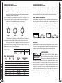
NATIONAL PARTS & SERVICE HOTLINE:
1-800-247-5767
WEB SITE: www.paceamerican.com
Manufacturing Facility
Dealer Location
TRAILER
USER’S
GUIDE
Pace American Inc.
11550 Harter Drive
Middlebury, IN 46540
574-825-7223
Fax: 574-825-7393
Pace American of Georgia
223 Rip Wiley Road
Fitzgerald, GA 31750
229-423-7966
Fax: 229-423-3859
Pace American of Utah
210 North Highway 91
Hurricane, UT 84737
435-628-7667
Fax: 435-628-7677
Pace American of Texas
2290 McGuffey Road
McGregor, TX 76657
254-840-4323
Fax: 254-840-4002
2
1
Introduction to Pace American
General Trailer Maintenance
Loading Your Trailer
2
3
7
Tongue Jacks & Landing Gear
Trailer Towing Safety Tips
Hitching Up Your Trailer
18
19
21
Hitch Selection Chart
Electrical and Wiring Systems
Trailer Wheel Bearings
Brake Adjustment/Maintenance
Tire Load Limits
Vendor Doors
8
9
11
15
16
17
Trailering Tactics
Safety Checklist
Pace Replacement Parts
Trailer Information Form
Maintenance Schedule/Record
Warranty Information
22
24
25
26
27
29
CUSTOMER
SERVICE
HOTLINE
1-800-247-5767
USER’S GUIDE CONTENTS
™
LEGACY
BY PACE AMERICAN
You have chosen a quality trailer from America’s most popular trailer
manufacturer—Pace American. Even though Pace American trailers are built for
the long haul, proper and routine maintenance will assure
even more years of hassle-free operation.
Pace recommends you consider the inspection and
service guidelines outlined in this easy-toR understand manual. Following these simple
FAI
•
A
instructions will help maintain proper operation
STT ● F
F● A
FAS of electrical systems, wheels, bearings, hitches, and
•
STEST
E
ON
N
H
other important function devices on your trailer. Should you have
HO
a problem, a Pace representative will review your warranty and take action
to correct the problem
immediately. Your complete
satisfaction has and will
always be our first objective at Pace. Please keep
this manual in your trailer or
tow vehicle and review the
safety checklists before
you set out on the road.
For factory-installed options and accessories such as air conditioning units,
awnings, heaters, winches, TVs and sound systems, refrigerators and other
such items, consult the separate manufacturer’s owner’s manual you received
with your trailer. And should there be a problem in workmanship or material, a
service hotline is always open.
Again, thank you for choosing a quality Pace American trailer!
INTRODUCTION TO PACE AMERICAN
THANK YOU FOR CHOOSING A PACE AMERICAN TRAILER
USER’S GUIDE CONTENTS
4
3
GENERAL MAINTENANCE
BREAKAWAY SYSTEM
DOT regulations require that a trailer’s battery keep or hold the trailer from rolling forward for 15-minutes after stopping. Check the battery on a regular basis for
adequate output and charge if necessary. The proper hookup for cable is to loop it
around something permanent on the tow vehicle but not the ball hitch insert or
hitch. If there is a failure of any of these
THE BATTERY SUPPLIED WITH
items, the plug pulls out of the switch
THIS KIT IS RECHARGEABLE
AND MUST BE MAINTAINED.
and activates brakes. The plug must
be pushed in completely so the brakes
are not dragging. This will drain the
battery if the pin remains pulled out.
ROOF VENTS
Roof vents on all Pace American trailers are designed to allow light into the
trailer during the daytime along with fresh air. Also warm air will escape when
the vent is open. However, your roof vent is not designed to be open when
traveling. Make sure that all vents are closed prior to towing over the road.
FRAME MAINTENANCE
Cargo trailers take the worst kind of abuse on the underneath, frame side.
Anything thrown up by the tow vehicle will chip away at the frame coating. It
is suggested that inspections are made periodically and any bare spots be
touched up with undercoating.
• CHECK CONDITION OF BATTERY
AND CHARGE PRIOR TO TRIP.
• CHARGE BATTERY PER
ENCLOSED INSTRUCTIONS.
• DO NOT EXCEED 1.2 AMPS
MAX. CHARGE.
INLINE CHARGER IS AVAILABLE THROUGH PACE AMERICAN
ROOF MAINTENANCE
Inspect the roof coating once a year. Check for shrinking or cracked sealant that will lead
to roof leak. Pace uses high quality self leveling caulk which is available through Pace or
local RV dealers. Do not allow excessive snow build-up on the roof. Brush snow off of
roof after a heavy snow. The excessive weight may damage trailer voiding warranty. Do
not walk on trailer’s roof unless you ordered a trailer with extra support for that purpose.
GENERAL MAINTENANCE
EXTERIOR SKIN MAINTENANCE
Clean exterior aluminum streaks with Black Streak Remover. Wash exterior
often with a soft brush and a quality
RV or Trailer Wash and Wax solution.
• ALL FLOOR AND RAMP SURFACES ARE SLIPPERY WHEN
COVERED WITH ICE, SNOW OR WET.
FLOOR TREATMENT
• TO PREVENT WARPING AND ROTTING OF FLOORING,
REMOVE STANDING SNOW AND WATER AFTER EACH USE.
To promote longevity and ease of
• FOR BEST MAINTENANCE OF EXTERNAL FINISH, WASH
ROAD SALT OFF TRAILER AFTER EACH USE.
clean-up on your plywood floor we
suggest painting it with a good quality oil-based porch and deck enamel. This
will seal the floor and make oil clean-up and sweeping-out much easier. When
parking trailer housing recently used snowmobiles, tilt the trailer and open
doors to allow melted snow to run out. This will allow floor to dry.
(continued)
WHITE AND CHROME WHEEL MAINTENANCE
Your new wheels do require care to maintain their factory appearance. We
strongly suggest you take a few reasonable steps to protect your investment.
Typical road soils trap moisture which can cause corrosion over a period of
time. Brake dust is also corrosive and can cause pitting of the wheels finish.
These soils must be removed regularly, possibly weekly, depending on your
driving habits. After cleaning, always apply a coat of soft non-abrasive cream
wax to help prevent surface corrosion. Surface corrosion or rust can be prevented with proper care and is not covered under warranty.
ALUMINUM RIM MAINTENANCE
Your wheels’ finish should be treated as you would treat the finish of your car.
The aluminum rims are clearcoated to preserve the finish and ease the cleaning. Most household cleaning agents are too harsh for the finish on your
wheels and must be avoided. Do not use any cleaning agent with a lye or acid
base. The only factory-approved wheel cleaner is: Aluminum Wash and
Brightener, Wheel Care Symbol F, by Eagle One. Always follow the manufacturer’s recommendations on the bottle for safe and effective cleaning.
TIRES, RIMS AND LUGNUTS
This trailer is equipped with quality
• ON THE FIRST TRIP, TIGHTEN WHEEL LUGS AT START AND
AT 10 MILES, 25 MILES AND AGAIN AT 50 MILES.
tubeless tires. The recommended
• THEREAFTER, CHECK WHEEL LUGS BEFORE EACH TRIP.
air pressure is found on the tire • FOLLOWING WINTER STORAGE, CHECK BEFORE
BEGINNING A TRIP.
sidewall. Always replace tires with • FOLLOWING EXCESSIVE BRAKING, INSPECT WHEEL LUGS.
the same designated type and size.
It is extremely important to apply and maintain proper wheel mounting torque
on your trailer axle. Torque is a measure of the amount of tightening applied
to a fastener (nut or bolt) and is expressed as length x force. For example, a
force of 90 pounds applied at the end of wrench one foot long will yield 90
GENERAL MAINTENANCE
GENERAL MAINTENANCE
6
5
GENERAL MAINTENANCE
(continued)
lbs.-ft. of torque. Torque wrenches are the best method to assure the proper
amount of torque is being applied to a fastener.
NOTE: Wheel nut or bolts must be applied and maintained at the proper
torque levels to prevent loose wheels, broken studs, and possible dangerous separation of wheels from your axle.
Be sure to always use only the fasteners matched to the cone angle of your
wheel (usually 60° or 90°). The proper procedure for attaching your wheels is:
1. Start all bolts or nuts by hand to prevent cross threading.
2. Tighten bolts or nuts in the following sequence.
1
1
1
4
3
6
6
3
3
8
5
2
5 BOLT
4
7
4
5
2
6 BOLT
8 BOLT
GENERAL MAINTENANCE
1st Stage
20/25
ft. lbs.
WHEEL TORQUE REQUIREMENTS
AXLE
WHEEL
STUD
SIZE
SIZE
SIZE
2000#
13"
1/2”
3500#
15"
1/2”
5200#
15"
1/2”
6000#
16"
9/16”
7200#
16"
9/16”
8000#
12"-16.5"
5/8”
8000#
17.5"
5/8”
2nd Stage
55/80
ft. lbs.
STEEL WHEEL
TORQUE
50#-75#
90#-120#
90#-120#
90#-120#
90#-120#
90#-120#
275#-325#
Warranties on axles and trailer will not apply to damage or injuries caused by
loose or improperly tightened lug nuts or broken studs. Inspect wheel stud
holes for roundness. If oblong, this is a sure sign that the unit has been run with
improperly tightened lugnuts. In these instances, the rim must be replaced.
DOORS, BARLOCKS AND RAMP HINGES
Door holdbacks are designed to hold doors open when on uneven ground. They
are not designed to hold doors open under windy conditions. Lubricate all door
and ramp hinges every 3 months with a SAE 30 weight engine oil. WD-40 and
similar lubricants will free hinges, however, they will also lose all lubricating qualities within a short period of time. Use a conventional grease gun tip to apply
grease at ramp hinges.
5
2
RIGHT
3. The tightening of the fasteners should be done in stages. Following the
recommended sequence, tighten fasteners per wheel torque chart below.
4. Wheel nuts/bolts should be torqued before first road use and after each
wheel removal. Check and re-torque after the first 10 miles, 25 miles, and
again at 50 miles. Check periodically thereafter.
TORQUE STAGES
(continued)
3rd Stage
Full Torque
ALUMINUM WHEEL
TORQUE
N/A
90#-120#
90#-120#
90#-120#
90#-120#
N/A
N/A
Parallel with ground and tow vehicle
WRONG
Trailer not level, adjust hitch
HITCH HEIGHT
You must adjust the hitch ball height to position tag trailers in a level condition.
This loads the axles equally and gives a desirable tongue weight. Under these
conditions your trailer should ride properly and not sway back and forth.
COUPLER OPERATION
Check the coupler or Kingpin for fatigue, damage,
CHECK COUPLER SIZE
cracks or missing parts before towing. Test the lock
PRIOR TO HOOKUP
mechanism for complete and correct latching so the
trailer will not come unhooked. For ball type couplers, make sure the coupler
and ball size match. If you are using a bumper hitch type coupler, it is recommended to put a bolt or similar device through the latch mechanism when
hooking to the tow vehicle for safety. It is advised that mini fifth wheel hitches
should have a wheel diameter that is close to the width of Pace American’s
Pinbox. A smaller wheel diameter does not get adequate vertical support from
the Pinbox and pushes the bottom plate upward.
GENERAL MAINTENANCE
GENERAL MAINTENANCE
8
7
Always refer to your car or truck manufacturer’s owner’s manual for additional trailer towing information and limitations.
Class IV
Weight-Distributing
Hitch
Class II
Frame Hitch
Class I
Sportframe
Class I
Sportframe
Minivans
Full-Size Cars, Pick-ups
Vans, Utility Vehicles
Class II
Frame Hitch
Class I
Sportframe
Sportframe Deluxe
Class II
Frame Hitch
Class IV
5,000–10,000 lbs. (GTW)
500–1,000 lbs. (TW)
Class I
2,000 lbs. (GTW)
200 lbs. (TW)
Class II
3,500 lbs. (GTW)
300 lbs. (TW)
Mid–Size Cars/
Small Pick-ups
YOU MUST HOOK TRAILER TO
SECURE THE LOAD
TOW VEHICLE WHEN LOADING,
Motorcycles, cars and cargo should be
ESPECIALLY WHEN LOADING
secured in your trailer. Pace American offers
TRAILER FROM THE REAR.
various solutions and items such as wheel
chocks, E-track and a variety of tie-down rings installed wherever you wish
inside the trailer. Your trailer must be hooked to the tow vehicle when loading or
unloading a car or heavy item from the rear. Inspect E-track and tie-downs regularly for cracks or damage that may weaken them or cause them to fail.
TOW
VEHICLES
70% OF
WEIGHT
TRAILERS
30% OF
WEIGHT
JUDGING TONGUE WEIGHT
The desired hitch weight is 10% of the
total loaded trailer weight. If scales are
not readily available, you may estimate your total loaded hitch weight by comparing a known weight to the hitch weight. The proper way, however, to
accurately measure tongue weight is by taking your loaded trailer to a local
scale, such as those found at gravel companies or highway weigh station
scales. Weigh the trailer and then the tongue separately and the tongue should
be 10% of total loaded trailer weight. 10% tongue weight is necessary for safe
towing and handling of trailer. To obtain the correct tongue weight, the trailer
must be setting level to the ground.
HITCH SELECTION CHART
For a gooseneck type trailer you should load 70% of your cargo’s weight in the
front of the trailer as depicted below This will put approximately 10% of the
loaded trailer weight on the hitch. If there is insufficient or too much hitch
weight, the trailer will not tow properly.
Class IV
Weight-Distributing
Hitch
Class V
10,000–14,000 lbs. (GTW)
1,400 lbs. (TW)
(continued)
LOADING TRAILER
You should load 60% of your cargo’s weight in the front of the trailer. This will
put approximately 10% of the loaded trailer weight on the hitch. If there is
insufficient hitch weight the trailer will not tow properly. It could be unstable,
difficult to control, and make towing unsafe. Proper weight distribution is
imperative and diagramed below.
40% OF
60% OF
Always secure trailer to tow vehicle
WEIGHT
WEIGHT
when loading or unloading, especially
from the rear of trailer.
GENERAL MAINTENANCE
HITCH SELECTION CHART
GENERAL MAINTENANCE
10
9
ELECTRICAL AND WIRING
GREEN
Use 8ga for
triple axle units
2 TRAILER CONNECTOR
2
3
3 BREAK-AWAY SWITCH
TOW VEHICLE WIRING
110 VOLT POWER INLET
15 Amp Motorbase
Extension Cord
30 Amp Motorbase
NEMA L 530
30 Amp Lifeline
NEMA 3830 Rcpt.
50 Amp Lifeline
NEMA 3894 Rcpt.
4 ROADSIDE BRAKE ASSEMBLY
4
4
4
4
GROUND
LEFT TURN
RUNNING
LIGHTS
WHITE
1
YELLOW
Use 10ga for single
& tandem axle units
YELLOW
1 BRAKE CONTROLLER
BROWN
RIGHT TURN
Tow vehicles must have the correct plug at the hitch
and be connected to the correct tow vehicle circuits
using acceptable practices in wire routing and connections. Pace uses two different types of plugs. Trailers
that are not equipped with brakes will have the 4-way
4-WAY PLUG
flat plug like the wiring code pictured at right.
TRAILER END
All other trailers will have the larger 7-way plug
which accommodates electric brakes and a separate
line for inside lights.
The inside lights are
wired to the #4 post.
THIS TRAILER IS EQUIPPED WITH 120 VOLT/60 HZ/AC
(HOUSE CURRENT) ELECTRICAL POWER. UL APPROVED NON-METALLIC SHEATHED CABLE (IE. ROMEX) HAS
The auxiliary center post is used for backup
BEEN INSTALLED IN THE WALL/ROOF CAVITY OF THE
TRAILER. PROCEED WITH CAUTION WHEN ATTACHING
EQUIPMENT TO THE TRAILER OR CUTTING INTO THE
lights or other special order/use wiring.
ROOF OR WALLS OF THE TRAILER.
IF YOU ARE IN DOUBT, CALL
It is important to ground the wiring propPACE CUSTOMER SERVICE AT 1-800-247-5767
erly. The ground wire should run from the
plug and attach to tow vehicle’s frame. Hitches, coupler/ball, safety chains
and load leveling equalizer bars will NOT provide an adequate continuous ground and may result in electrical
system failure. In addition, any hot line or auxiliary
4
3
line should be run with an in-line fuse.
If an auxiliary battery is added to the trailer,
6
5
7
there must be a fuse installed between the battery
and the load.
2
1
Pace recommends that a separate fused line be
run from the tow vehicle’s battery, through a 20 Amp inline fuse, to an aftermarket toggle switch mounted on the
TOW VEHICLE
dash. This switch should have a 20 Amp capacity. Wiring
RECEPT.
WHITE
1 GROUND
should be run from the switch to the #3 post for running
BLUE
2 BRAKES
lights. Newer vehicles’ wiring and headlight switches are
GREEN
3 RNG LTS
many times marginal and do not have the capacity to
BLACK
4 HOT LINE
carry the current required for larger trailers with lots of
RED
5 L/H TURN
BROWN
6 R/H TURN
running lights. If your tow vehicle has amber turn signals,
YELLOW 7 AUXIL.
see your hitch & wiring specialist for installation of a relay
or "splitter" to operate your trailer turn signals and brake lights. The hot line
should have a 15 Amp in-line fuse installed between battery & tow vehicle plug.
ELECTRICAL AND WIRING
TOW VEHICLE WIRING
12
11
Trouble-free trailering depends upon proper bearing lubrication, maintenance
and inspections. Bearings fail when lubrication fails or when improperly adjusted. In both cases, heat build up occurs. Normal bearing operating temperate
is up to 140° and can be touched by hand without
burning. Above this temperature, the grease will start
INACTIVITY CAN
to fail and destroy the bearings, drum and/or the
BE MORE DAMAGING
spindle. Brakes are designed to operate at up to
TO BEARINGS THAN
EVERYDAY USE
600°F. A good practice for both experienced and new
trailer owners is to touch each hub within ten miles of starting out when bearings have been repacked and at each stop along the way. (Do not try testing
the hub after several miles of continuous hard braking). This will give an
advanced warning of pending trouble so corrections can be made prior to failure and breakdown. Remember, inactivity can be more damaging to bearings
than every day use. When a trailer is parked, many times the spindle, bearings
BEARING, RACE & SEAL NUMBERS
Axle Size
2000#
Brake Size
N/A
14
1 2 3
11
4 5 10
5200#
6000#
7200#
8000#
10 x 2
12 x 2
12 x 2
12 x 2
121/4 x 33/8
1/4
1/2
Typical Bolt Pat. 5 on 4 ”
Bolt Circle
5 on 4 ”
Bolt Circle
6 on 5 “
Bolt Circle
8 on 6 ”
Bolt Circle
8 on 6 ”
Bolt Circle
8 on 61/2”
Bolt Circle
Inner Bearing
L44649
L68149
25580
25580
25580
25580
Inner Race
L44610
L68111
25520
25520
25520
25520
Outer Bearing
L44649
L44649
LM67048
14125A
02475
02475
Outer Race
L44610
L44610
LM67010
14276
02420
02420
1/2
1/2
1/2
1/2
1/2
GREASE SEALS
2000#
2500#/3500#
5200#
6000#
7200#
8000#
—
—
—
442109
—
—
National
NOK
13
2500#/3500#
AD2548-EO
—
—
—
—
Chicago Rawhide 533409
AD2267-EO
—
—
—
—
—
Dexter Replacements
010-019
010-036
010-036
010-063
010-063
Magnet Kit
N/A
K71-104
K71-105
K71-105
K71-441
K71-375
Shoe & Lining
N/A
K71-047
K71-048
23-105/23106
K71-048
23-105/23106
K71-410
23-105/23106
K71-049 LH
23-105/23106
Electric Brakes
23-26/23-27
All Parts are available through Pace American Corporate Pars Dept., Middlebury, IN at 800-247-5767
Exp3500
12
EXP3500.eps
9-28-94
4/4/96 1. Grease Seal for E-Z Lube
TM
2. Inner Bearing Cone
WHEEL BEARINGS
Inner Bearing Cup
3,5003.lbs.
4. Outer Bearing Cup
5. Outer Bearing Cone
6. Special Jam Nut
7. Spindle Nut Retainer
6 7 8
8. Grease Cap for E-Z LubeTM
9. Rubber Plug for E-Z LubeTM
10. Spindle Washer
11. 1/2-20 Pressed Wheel Stud
12. Lug Nut
13. LH/RH Electric Brake
14. Hub/Drum
9
or hub is warm. As these cool down, a spot of condensation forms which is
the start of a rust spot. The longer the trailer sits idle, the deeper this rust spot
becomes. When in doubt of the coverage of grease on bearings—inspect and
replace those that have rust spots, metal flaking, wear, cage damage or other
visual damage.
If you ever have questions regarding maintenance requirements or how to perform a maintenance task, please do not hesitate to contact us at our customer
service hotline listed below or on the back of this manual. A Pace representative will be glad to answer your questions. Ask for a Customer Service
Representative at:
1-800-247-5767
WHEEL BEARINGS
WHEEL BEARINGS
14
1
2
7
8
REMOVE HUB ASSEMBLY
Pry dust cap off with screwdriver. Straighten out
tang washer. Remove spindle nut, tang washer and
spindle washer. Pull hub toward you to loosen outer
bearing. Do not let bearing fall. Pull the hub assembly off spindle. The inner bearing and seal will come
with it. Pry out the inner seal and discard. The inner
bearing will now come out. Caution- do not remove
seal by hitting the inner bearing.
INSPECT BEARING RACES (CUPS) AND HUB
Inspect races for pitting, rusting, frosting, scoring, metal flaking and other obvious damage. If
damaged, remove with brass bar or mild steel
bar. Inspect race seat and remove any burrs or
nicks that prevent the race from seating correctly. Replace races and bearings in sets.
INSTALL HUB ASSEMBLY
Slide the hub over the spindle with care not to
damage the seal or spindle threads.
Seat the hub against the seal journal. Insert the
outer bearing, D-Shaped spindle washer, tang
washer, and spindle nut.
3
4
9
CLEAN AND INSPECT THE SPINDLE
Clean spindle with solvent to remove old
grease. Inspect the spindle for nicks, scratches, scoring, damaged threads, or bending.
File off nicks or burrs and smooth out with
emory cloth. Apply thin film of bearing grease
to spindle.
CLEAN AND INSPECT BEARINGS (CONES)
Clean bearings with solvent and long bristled
brush. Do NOT use air pressure to clean out old
grease or to dry. Allow to air dry. Inspect bearings for pitting, rusting, frosting, scoring, metal
flaking, cage damage or other obvious damage. Replace all damaged bearings and mating
races in sets.
ADJUST BEARING
Using a 12” wrench on the spindle nut apply
50ft-lb of torque at the same time the hub is
rotated counterclockwise. Leave the hub stationary while backing off the spindle nut to
relieve the preload torque. Then hand tighten
5
6
INSTALL RACE (CUP)
Using a brass bar or a mild steel bar to drive in
new race into hub until solidly seated against
hub shoulder. Use caution to not damage race
surfaces. Never use a bearing to drive a race.
INSTALL GREASE SEAL
Install new seals when they leak or when bearings are being visually inspected. Install inner
bearing in hub, then the seal. Make sure the
seal is installed correct side in. Use soft wood
to seat seal in flush with hub.
11
FILL WITH GREASE
Apply nozzle of grease gun to the grease zerk
at the end of the spindle. Pump grease into the
assembly until it comes out around the spindle
washer.
10
the spindle nut to the first slot that lines up
with a tang on the washer. Flatten the tang
into the slot as far as it will go. Use caution
that the tang is not fractured in this step. The
correct adjustment for all bearings is .001 to
.012 end play.
12
INSTALL DUST CAP
Install dust cap with rubber plug. Care must be taken
so that cap goes on evenly and is not crimped on
inner lip. Cap is fully seated when rib on the cap is up
against the hub all the way around. This prevents
grease from being thrown out of hub onto the rim.
WHEEL BEARINGS
WHEEL BEARINGS
13
16
Actual unit or axle load ratings will be determined by the lowest rated component (Tire, Wheel, or Axle)
3695
Note: Load capacity limited to 4500 lbs. @ 125 PSI with Dexter 17-241 single wheel
215/75R17.5
The information shown above is valid only for trailer (ST) or light truck (LT) design tires. Passenger car tires (P designation) used in trailer service must be de-rated 10% from the maximum load
capacity branded on the tire sidewall (branded load capacity divided by 1.10 equals the load capacity for trailer service.)
4340 4495 4650 4805(H)
4180
3860 4020
3415 3550
2485 2623(D) 2765 2905 3042(E) 3170 3300
2335
1700 1870 2030
LT235/85R16
2600
2090(B) 2270 2430
ST235/80R16
2205
2730 3000(D)
2380 2540(D)
2270
2150
1760 1880 2020
1480 1610 1720 1820(C)
Note: capacity limited to 2150 lbs. @ 50 PSI when mounted on 5 bolt wheel
1600
1360
1260
ST225/75R15
1430
1070
ST205/75R15
1120
1430 1530 1640 1760(C)
1300
1030
ST205/75R14
1170
1480 1610 1720 1820(C)
1360
1070
F78-15 bias
(ST205/75D15)
1120
1430 1530 1640 1760(C)
1300
1030
F78-14bias
(ST205/75D14)
1170
1100 1190 1270 1360(C)
1000
905
795
B78-13 bias
(ST175/80D13)
25
Note: Load range G tire requires compatible wheel, cannot be used with standard 16" wheels
1045(C)
840(B)
5.30-12 bias
EZ-LUBE HUBS
See EZ-Lube Hub instructions in Dexter service manual. Lube hubs every 12
months or 12,000 miles. Check the Dexter Service Manual for recommended
wheel bearing lubrication specifications.
PSI 20
Spring Loaded
Double Lip Seal
TIRE SIZE
TRAILER BRAKES
Grease Zerk
Metal End Cap
3675 3750(G)
125
115
110
105
100
95
90
85
80
75
70
65
60
55
50
45
40
30
Grease
Flow
35
Rubber Plug
(Letters in parenthesis denote load range for which BOLD FACE loads are maximum)
Outer Bearing
& ADJUSTMENT SEE
ENCLOSED DEXTER SERVICE
MANUAL.
Inner Bearing
TIRE LOAD LIMITS (LBS) AT VARIOUS INFLATION PRESSURES (PSI) COLD
See your hitch specialist for your brake controller. They will provide a brake
controller manual which gives information on proper controller adjustments.
Load and road conditions will require different sensitivity settings of the controller. Heavy loads will need maximum sensitivity as opposed to an empty
trailer which will require a very light braking action.
*FOR ADDITIONAL SERVICE
MATCH AIR PRESSURE & TIRE CAPACITY TO WEIGHT ON AXLES
1.) Jack up trailer and secure on adequate capacity jack stands. Lifting and supporting must be on the main I-beams or the perimeter tube frame that the axle is
attached to. Check that the wheel and drum rotates freely.
2.) Remove the adjusting hole cover from the adjusting slot on the bottom of the brake
backing plate.
3.) With a screwdriver or standard adjusting tool, rotate the starwheel of the adjuster
assembly to expand the brake shoes. Adjust the brake shoes out until the pressure of the linings against the drum makes the wheel very difficult to turn.
4.) Now rotate the starwheel in the opposite direction until the wheel turns freely with
a slight lining drag. Usually 8 clicks.
5.) Replace the adjusting hole cover and lower the wheel to the ground.
6.) Repeat the above procedure on all brakes.
120
Brakes must be adjusted after the first 200 miles of operation when the brake
shoes and drums have seated. After the initial adjustment the brakes should
be readjusted at 3000 mile intervals or as use and performance requires. The
brakes should be adjusted in the following manner:
TIRE LOAD LIMITS
TRAILER BRAKES –BRAKE ADJUSTMENT*
USE ONLY APPROVED TIRE AND
WHEEL COMBINATIONS. FAILURE
TO DO SO OR FAILURE TO COMPLY WITH LOAD AND INFLATION
LIMITS MAY RESULT IN SERIOUS
INJURY OR DEATH.
15
18
17
TONGUE JACKS FOR BUMPER- PULL MODELS
If your trailer was ordered with a vendor door(s), it may have the ratchet style
door prop to open the door. The operation of this type of prop is to swing the
door open until the ratchet system engages and holds the door open. There will
be a safety pin provided for each door prop that must be installed. This ensures
the door will not come down. To release the prop system, first remove the safety pin, then lift the door slightly to release
the ratchet assembly system. If the door is
SAFETY PINS ARE PROVIDED FOR USE ON
pulled downward without first lifting, the
THE VENDOR DOOR PROPS. WHEN IN THE
OPEN POSITION, SAFETY PIN SHOULD BE
ratchet system will be damaged.
INSERTED THROUGH THE INNER AND
Pace American also offers the OUTER SLIDES TO PREVENT INADVERTENT
UNLATCHING OF THE PROP.
option of gas shocks to assist in the opening of the vendor door, especially helpful with heavier, large doors. After
unlatching the door, install one end of each of the pipe-style props provided
into the “camel back” bracket mounted on the lower side of the vendor door.
One prop goes on each end of the door. After installing both props onto the
vendor door, lift the door and allow the gas shocks to push up to the full open
Pace American uses two types of manual tongue jacks. Lubrication and proper maintenance of jacks will enhance jack life and make operation smoother.
The two types that Pace American uses are: 1) the side-wind model and 2) the
top-wind model. The internal gearing and bearings of the jack must be kept
lubricated. Using a needle nose applicator, pump a small amount of automotive
grease through the lubrication opening. The lubrication opening can be found
on the side of the jack tube, directly
below the handle. Rotate the jack handle to distribute the grease evenly.
Lightly grease the inner tube of the
jack using the same type of grease. A
lightweight oil must also be applied to
the handle unit at both ends of the
outer tube. The top-wind jack has an
access hole on the front side that will
allow oil to be sprayed into the threaded rod. By using a product similar to
ANTI-SEIZE TECHNOLOGY’s product no. 17061, you will be able to free up
rusty and corroded parts, and it leaves a protective anti-rust film. Some sprayon lubricants will only provide short term lubrication and will need to be
reapplied more frequently than once a year.
VENDOR DOORS AND TONGUE JACKS
FIFTH WHEEL AND GOOSENECK LANDING GEAR
The vendor door on the left is held open by a ratchet style prop that
requires a safety pin. The swing-out arm is shown on the right.
position. Next, install the bottom end of the pipe props into the “camel back”
brackets mounted on each side of the opening. Use of these pipe props
ensures the doors will not close due to high wind when people may be standing underneath the vendor door. To close doors, unfasten the lower end of the
pipe props and pull the door down by using the pipe props.
These kinds of trailers are equipped with a two-speed, twin landing gear. Low
speed eases the raising of the unit. High speed will rapidly retract the legs into
the travel position. The shaft that the crank handle attaches to is what accomplishes this gear change. Pushed IN sets the high speed operation while pulling
OUT is low speed. If you have questions, please contact us at the Customer
Service Hotline toll-free number: 1-800-247-5767.
TONGUE JACKS AND LANDING GEAR
VENDOR DOORS
20
19
TRAILER TOWING SAFETY TIPS
INSTABILITY
Swaying (or whipping) of a tow vehicle/trailer combination at low speeds may
get worse as speed increases. If this happens, take your foot off the gas pedal.
Steer straight ahead while manually applying the
trailer brakes. Then brake gently after the combination has begun to stabilize itself. Stabilizer or weight
NEVER INCREASE
SPEED WHEN TRAILER
equalizing bars will help reduce trailer sway and may
IS SWAYING
also be required by law in some states.
OR WHIPPING
Check cargo first to be sure that the trailer is
loaded heavier in the front. If not, reposition the load so you get 10% of the
total trailer weight on the tongue. Next, make certain the rear of the tow vehicle is not overloaded. Then check for wheel wobble on both vehicles caused
by bearing failure, loose lug nuts or loose spindle nuts. Now check the tow
vehicle’s suspension alignment. Finally, make sure that you are not exceeding
the recommended maximum speed limit for safety and IT’S THE LAW.
If the above instructions have been followed, instability should now be
corrected. If not, something may be wrong with your tow vehicle.
TIPS FOR THE BEGINNER (ALSO SEE HITCHING UP ON P. 21)
Place your hand at the bottom of the steering wheel. While watching in your
outside mirrors, if you want the rear of the trailer to go to the right, move your
hand to the right. If you want the rear of the trailer to go to the left, move your
hand to the left. If the trailer starts to jackknife—STOP—pull ahead to straighten out then start procedure over again. When making turns, be aware the
trailer will turn quicker than a tow vehicle. Allow extra
turning space so that the trailer wheels don’t jump
over a curb, hit a soft shoulder, road sign or tree.
TRAILER TURNS QUICKER THAN TOW VEHICLE.
Your axle and/or tire and rim can be severely damALLOW EXTRA TURNING
aged as a result or from hitting the curb at a bad
SPACE FOR TRAILER.
angle and too hard.
CHECK YOUR POLICY
Most automobile and some homeowners insurance policies will provide some
coverage for cargo trailers. They should also provide for you a “grace period”
of a set number of days from the date of purchase. Call your agent.
HITCH AND BRAKE SAFETY
For safe towing it is the trailer owner’s responsibility to CORRECTLY MATCH
the combination of tow vehicle and trailer.
1. MATCH the maximum trailer weight allowed for the tow vehicle to the
GVWR of the trailer.
2. MATCH the hitch weight carrying capacity of the tow vehicle with the loaded
tongue weight of the trailer. This is generally 10% of GVWR on tag models
and 20% of GVWR on 5th wheels and Goosenecks. Tag models may require
a weight distributing hitch with sway controls. Contact your hitch specialist
to properly set up your tow vehicle/trailer combination.
3. MATCH the size of the brake controller to the number of braking wheels on
your trailer. These are sold usually as 2 to 4 wheel brake or 2 to 6 wheel brake
units. For proper controller adjustment, see your brake controller manual.
4. MATCH the wiring of the tow vehicle to the wiring code on the trailer. Ensure your
tow vehicle does have a ground wire running from the receptacle to the frame.
5. MATCH the ball size to the coupler size.
6. MATCH your Fifth Wheel or Gooseneck trailer to a correct and compatible
hitch provided by your hitch specialist. Then consult your hitch specialist for
proper maintenance of the hitch assembly.
7. Match your rear vehicle suspension to the loaded hitch weight of the rear
axle of the tow vehicle.
All marginal situations should be corrected for safe trailering. Remember, you
are the one that will be trying to control a large combination of weight and size
at high speeds. It is your responsibility to set up tow vehicle/trailer properly.
Contact or confirm your set up with a local hitch company professional.
GROSS TRAILER WEIGHT (GTW) & TONGUE WEIGHT (TW)
Class I
Class II
Class III
2,000 lbs. (GTW)
200 lbs. (TW)
Compact Cars
3,500 lbs. (GTW)
300 lbs. (TW)
Mid Size Cars & Small Pick Ups
3,500–5,000 lbs. (GTW)
300–500 lbs. (TW)
Minivans
Class III
Class IV
Class V
4,000 lbs. (GTW)
350 lbs. (TW)
Mid Size Cars
Small Pick Ups
Minivans
5,000–10,000 lbs. (GTW)
500–1,000 lbs. (TW)
Pick Ups
SUV's
14,000 lbs. (GTW)
1,700 lbs. (TW)
20,000 lbs. (GTW)
2,000 lbs. (TW)
Also see Hitch Selection chart on page 8
TRAILER TOWING SAFETY TIPS
TRAILER TOWING SAFETY TIPS
22
21
TRAILERING TACTICS*
Hitching up a trailer to your tow vehicle is usually a one-person job, but it is
easier if someone helps you. Here are a few of the basic steps:
With a trailer in tow, you’re operating a vehicle combination that is longer,
heavier and sometimes wider and taller, than you’re used to. So you’ll have to
make some compensating adjustments in your normal driving practices. The
following is advice in trailering tactics:
1. Back your tow vehicle as close as possible to the trailer. It is easier and
safer to do this than it is to pick up and pull the trailer to your car or truck.
2. Release the coupler locking device.
3. Raise the front end of the trailer. Place coupler directly over the hitch ball
then lower it until it is seated on the hitch ball, covering it completely.
4. Check under the coupling to ensure the ball clamp is below the ball and
not riding on top of it.
5. Latch the coupler to the hitch ball. Make sure it is locked in place by lifting up the trailer tongue. If the coupler comes loose form the ball, unlatch it
and go back to Step 3.
6. Make sure your jack is fully raised.
HITCHING UP YOUR TRAILER
7. If you have a weight distributing hitch with spring bars, follow the above
procedures. Then attach the spring bar chain to the trailer and tighten it until
your trailer and car are in a normal, level position.
8. If your trailer has a surge brake breakaway cable or chain, attach the
cable or chain to your tow vehicle, allowing enough slack for you to make tight
turns.
Take a “Shakedown Cruise”. At least one short trial run before your first trip
will help familiarize you with your trailer’s operating characteristics. It will also
allow you to check the trailer’s lights, brakes, hitch, etc., and let you know they
are all working properly.
Slow down. Moderate to slower driving speeds put less strain on your tow
vehicle and trailer and make for safer traveling.
Allow extra time and space between your rig and traffic. You will need both
when passing and stopping, especially if your trailer is not equipped with
brakes.
Check rear view mirrors. Doing this frequently will let you know that your
trailer is riding properly. We recommend outside rear view mirrors on both
sides of your tow vehicle.
Swing wider. You need to make wider swings (turns) at curves and corners
because your trailer’s wheels are generally closer to the inside of a turn than
the wheels on your tow vehicle.
Pass with extra care and caution. It takes more time and distance to get
around a slower vehicle and return to the correct lane when you’ve got a trailer in tow.
9. Attach the safety chains as described on page 22.
10. Connect the trailer wiring harness to the lighting system of your tow
vehicle and check its operation (also see page 9 in this manual for details).
* Hitching Up courtesy of REESE PRODUCTS, INC.
Watch the wind direction and speed. To avoid swaying, be prepared for sudden changes in air pressure and wind buffeting when larger vehicles pass from
either direction. Slow down a bit and keep a firm hold on your steering wheel.
Aim straight down your lane.
Conserve fuel. You’ll go farther on a tank of gas at moderate speeds. Higher
speeds increase wind resistance against the trailer and reduce fuel mileage.
TRAILERING TACTICS
HITCHING UP YOUR TRAILER*
24
23
Avoid sudden stops and starts. This can cause skidding, sliding, or jackknifing, even if your trailer has brakes. Avoid quick stops while turning.
Smooth, gradual starts and stops will improve your gas mileage.
Signal your intentions. Let surrounding vehicles know what you intend to do
well in advance before you stop, turn, change lanes, or pass.
Shift to a lower gear. A lower gear will help ease the load on the transmission
and engine when going over steep hills, sand, gravel, or dirt roads. If your tow
vehicle has an “overdrive” gear, shifting out of overdrive to a lower gear may
improve your gas mileage.
Always be courteous. Make it as easy as possible for faster moving vehicles
to pass you. Keep to the right of the road and prepare to slow down if passing vehicles need extra time to return to their proper lane.
TRAILERING TACTICS
Don’t tailgate. Allow at least one car and trailer length between you and the
vehicle ahead for each 10 mph on your speedometer. Three seconds should
be the minimum distance.
If a problem occurs don’t panic. Stay calm and cool. Say you experience a
sudden bumping or fishtailing. It may indicate a flat tire. Don’t jam on the
brakes or mash the accelerator in an attempt to drive out of it. Instead, come
to a stop slowly as you keep driving in as straight a line as possible. If conditions permit, coast to a very slow speed and try to avoid braking, except when
your wheels are straight ahead and your trailer and tow vehicle are in line with
each other.
If your trailer begins to fishtail as you accelerate to highway speed, back
off the accelerator a bit. This should stop the fishtailing. If it begins again as
you increase speed, stop and check you load. It probably isn’t distributed
evenly from side to side, or it is too far back to put a sufficient load on the hitch
ball. It is recommended that 10% of the trailer load be on the hitch. (See page
19 for more details). Redistribute the load as necessity dictates before continuing on the highway.
* Trailering Tactics courtesy of REESE PRODUCTS, INC.
SAFETY CHECKLIST
❏ Maintenance Checklist (Up to Date)
❏ Hitch Ball Tight
❏ Hitch Ball Lubricated
❏ Hitch Secured in Receiver
❏ Safety Chains Crossed and Attached*
❏ Coupler Latched onto Ball
❏ Load Distributed Correctly and Securely
❏ Trailer Level when Hooked Up
❏ Trailer Lights Working Correctly
❏ Lug Nuts Checked and Tightened
❏ Inspect Tires for Cuts
❏ Tire Pressure Checks
❏ Breakaway Battery Charged
❏ Breakaway Cable Hooked Up
❏ Pin or Bolt through Coupler Latch
❏ Block Tires when Loading and Unloading
* If safety chains are too long, twist to shorten.
THE MAIN CAUSES OF TRAILERING ACCIDENTS
1. Driver error.
2. Failure to MATCH speed with weather and road conditions.
3. Trailer sway due to improper loading — more or less than 10% cargo hitch
weight.
4. Failure to perform routine maintenance.
Remember, never carry passengers in trailer while moving. Check hub temperature at each stop. Adjust sensitivity of brake controller to match load. 102" axles
are legal on all Federally-funded highways (and some state highways).
SAFETY CHECKLIST
TRAILERING TACTICS* ( continued)
26
25
FACTORY SERVICE
Call the Customer Service Hotline for your nearest Pace American factory
location to schedule quality factory service, retrofitting, reskining, accident
repairs or any other service your dealer can’t do. And let Pace handle the
jobs your dealer may not want to do. Whatever it takes, Pace is dedicated to
your complete satisfaction.
Replacement parts are available through Pace. Call
your authorized dealer or the nearest Pace American
manufacturing plant. Be prepared to give the following information including everything listed on the
Trailer Information Form located opposite this page:
VIN and Model Number:
TRAILER INFORMATION FORM
/
Description of Part, Size, Color, Location on trailer, etc.:
Most small parts are shipped via ground UPS.
All larger parts orders will be crated and shipped
by truck freight lines.
CUSTOMER
SERVICE
HOTLINE
1-800-247-5767
Fill in the information form below for future use. This critical information should
be used for quick reference when ordering genuine Pace American replacement
parts, factory service or refer to it if you should have a warranty claim. Keep it
handy so Pace American can serve you promptly and efficiently.
Owner:
Address:
City:
State:
Zip:
City:
State:
Zip:
Model No:
Tire Size:
Date Purchased:
Dealership:
Dealership phone number:
PACE REPLACEMENT PARTS
Address:
Serial (VIN) No:
Color Name: (from copy of order)
Hitch Size:
TRAILER INFORMATION FORM
GENUINE PACE AMERICAN REPLACEMENT
PARTS AND ACCESSORIES
28
27
ITEM
COUPLER
EVERY
3000 MI
REQUIRED
TRIP
3 MONTHS
CHECK FOR FATIGUE &
•
6
•
23
•
3
•
4-5
•
7
•
10
LATCHING OPERATION
SAFETY
CHECK FOR DRAGGING &
CHAINS
POSSIBLE STRENGTH LOSS
BREAKAWAY
SYSTEM
LUGNUTS
PIGTAIL
LIGHTS
& SWITCH OPERATION
CHECK FOR CORRECT
TORQUE
CHECK FOR DRAGGING
& STRESS
CHECK THAT ALL ARE
OPERATING
CHECK FOR CORRECT
TORQUE & ELONGATION OF
BOLTS
THE SHACKLE LINK HOLES
CHECK PRESSURE &
UNUSUAL WEAR
BEARINGS
REPACK
HINGES
LUBRICATE
STABILIZER
LUBRICATE
JACK-SCREW
THREADED ROD
HYDRAULIC
CHECK FLUID
FLUID
LEVEL
ROOF
INSPECT FOR CRACKS
SEALANT
OR DRYING OUT
JACKS
BRAKES
12000 MI
PG
CABLE FOR DAMAGE
AXLE &
WHEELS
6000 MI
6 MONTHS 12 MONTHS #
CHECK BATTERY CHARGE
SPRING
TIRES
MAINTENANCE SCHEDULE
FUNCTION
INSPECT FOR CRACKS
INDENTATIONS
•
•
4
•
•
6
•
OPERATION
BRAKE
ADJUST FOR OPTIMUM
ADJUSTMENT
PERFORMANCE
INSPECT
FRAME WELDS
CHECK FOR
CRACKING
22
•
•
•
3
4-6
•
LUBRICATE
CHECK FOR
11-14
•
22
15
•
15
•
DATE
MILES
SERVICE PERFORMED
MAINTENANCE RECORD
MAINTENANCE RECORD
MAINTENANCE SCHEDULE
30
29
NOTES
THREE YEAR LIMITED WARRANTY
The Pace American, Inc. subsidiary whose name appears on your “Certificate of Origin” (PACE AMERICAN) warrants to the original owner that your PACE AMERICAN trailer will be free from defects in materials and workmanship for the period of three (3) years except as herein limited, from the date of the first retail purchase
provided all stated conditions and exclusions are met and satisfied. The obligation of this warranty shall be limited to repairing or replacing any part or parts which,
in the opinion of the factory are defective in materials or workmanship under normal use and service during the three(3) year period commencing with the date of
the first retail purchase. Electrical components, lights, mechanical jacks, fiberglass, doors, sealants, seals, locks, couplers, and paint are warranted for a one (1)
year period from the date of the first retail purchase, subject to the limitations contained in this limited warranty.
WARRANTY VALIDATION
A warranty registration certificate is included with the dealer paperwork. The dealer must fill out and mail this certificate to the factory within ten (10) days after making delivery of the trailer. This purchaser record is required by federal law. Failure to fill out and return this warranty registration certificate within the above period
will automatically void the warranty.
HOW TO OBTAIN WARRANTY SERVICE
1. All warranty requests must be presented to PACE AMERICAN and proper arrangements must be made and approved by the factory prior to any work being done.
2. All warranty repairs must be made at the PACE AMERICAN factory, unless prior written approval is obtained from the factory before said repairs begin. In certain cases, the PACE AMERICAN factory may, at its option, elect to have warranty work performed in the field by a qualified repair shop.
3. PACE AMERICAN will not be obligated in any way to pay for repairs made without specific written approval in advance, repairs made in any manner other than that
approved by PACE AMERICAN, labor charges in excess of those deemed reasonable by PACE AMERICAN or any parts, bills in excess of the cost if PACE AMERICAN
had supplied those parts. Labor and parts charges for any covered warranty work are limited to the amount charged by PACE AMERICAN for such labor and/or parts.
4. Except as described in this limited warranty, PACE AMERICAN will not pay any other charge or expenses including, without implied limitation, any charges
for overtime labor, service calls, towing charges or transportation costs. Such charges or expenses are the responsibility of the customer and will not be paid
for by PACE AMERICAN.
WHAT IS NOT COVERED BY THIS LIMITED WARRANTY
1. Items covered by another warranty:
Any claims on items that are covered by their manufacturer’s warranty must be presented to those manufacturers for adjustment. The
following items would be subject to the manufacturer’s warranty, including, but not limited to:
a. Axles and axle components including, without implied
g. Winches.
o. Stove/Cook Tip
limitation, tow in/tow out and camber on axles.
h. Electric Jacks.
p. Microwave
b. Tires: present a claim for tire adjustments to a tire dealer who handles
i. Hydraulic Jacks.
q. Furniture
the brand in question and is authorized to make the adjustments.
j. Food Service Equipment.
r. Water Pump
c. Rims.
k. Beverage Equipment.
s. TV, VCR, Stereo Equipment
d. Air Conditioners.
l. Water Heaters.
t. furnaces
e. Generators.
m. Refrigerators.
f. Awnings.
n. Landing Gear.
Subject to the other terms of this limited warranty, PACE AMERICAN warrants the proper installation of the above listed items.
2. Tow vehicle wiring.
3. Damage or wear caused by unreasonable use or failure to provide reasonable and necessary repairs or maintenance.
4. PACE AMERICAN will not be responsible for work performed or options installed by others. Customer will be charged for any labor, material, or parts
resulting from work performed or options installed by others, including without implied limitation:
a. Graphics.
b. Special Awnings.
c. Hydraulic Lift Systems.
5. Damage or defects resulting from or repairs required because of misuse including, but not limited to, overloading (as determined by the gross vehicle
weight rating and not payload capacity as shown on the vehicle identification label), improper loading, negligence, alteration, accident, or lack of
reasonable and proper maintenance.
6. Replacement of maintenance items that are worn out from normal use, including but not limited to bearings, magnets and brake shoes.
7. Deterioration of paint and appearance due to use and exposure.
8. Damages caused by loose or improperly torqued lug nuts.
9. Damages caused by the use of an incorrect or altered hitch ball or improper latching.
10. Damages caused by loose nuts, bolts or screws. Maintaining necessary tightness of these items is the owner’s responsibility.
11. Loss of time, inconvenience, loss of use of trailer, rental of substitute equipment, loss of revenues, or other commercial loss.
12. Trailers covered by this warranty are designed to be towed by a vehicle with up to one (1) ton capacity.
13. At no time should a towing vehicle be used with a trailer that exceeds the tow vehicle manufacturer’s specific limitations.
14. Tow vehicle wear.
ANY EXPRESSED OR IMPLIED WARRANTY NOT PROVIDED HEREIN, INCLUDING WITHOUT IMPLIED LIMITATION, ANY WARRANTIES OF MERCHANT-ABILITY OR FITNESS FOR A PARTICULAR PURPOSE, AND ANY REMEDY FOR BREACH OF CONTRACT, WHICH BUT FOR THIS PROVISION MIGHT ARISE BY
IMPLICATION OF OPERATION OF LAW, ARE HEREBY EXCLUDED AND DISCLAIMED. IF THEY CANNOT BE DISCLAIMED, ANY IMPLIED WARRANTIES OF
MERCHANTABILITY AND OF FITNESS FOR ANY PARTICULAR PURPOSE ARE EXPRESSLY LIMITED TO A TERM OF ONE YEAR. SOME STATES DO NOT
ALLOW LIMITATIONS ON HOW LONG AN IMPLIED WARRANTY LASTS, SO THE ABOVE LIMITATION MAY NOT APPLY TO YOU. UNDER NO CIRCUMSTANCES
SHALL PACE AMERICAN BE LIABLE TO PURCHASER OR ANY OTHER PERSON FOR ANY SPECIAL, INCIDENTAL OR CONSEQUENTIAL DAMAGES,
WHETHER ARISING OUT OF BREACH OF WARRANTY, BREACH OF CONTRACT, TORT OR OTHERWISE. SOME STATES DO NOT ALLOW THE EXCLUSION
OR LIMITATION OF INCIDENTAL OR CONSEQUENTIAL DAMAGES, SO THE ABOVE LIMITATION MAY NOT APPLY TO YOU. THIS WARRANTY GIVES YOU SPECIFIC LEGAL RIGHTS AND YOU MAY ALSO HAVE OTHER RIGHTS WHICH VARY FROM STATE TO STATE.
WARRANTY
NOT WITHSTANDING ANYTHING TO THE CONTRARY HEREIN, THIS LIMITED WARRANTY IS LIMITED TO REPAIR OR REPLACEMENT AND IF SUCH WARRANTY FAILS BECAUSE ATTEMPTS AT REPAIR ARE NOT COMPLETED WITHIN A REASONABLE TIME, OR IT FAILS FOR ANY OTHER REASON, ANY
DAMAGES ARE LIMITED TO THE LESSER OF EITHER THE COST OF NEEDED REPAIRS OR REDUCTION IN THE MARKET VALUE OF THE TRAILER CAUSED
BY THE LACK OF REPAIRS, IN ANY CASE.
The factory neither assumes nor authorizes any other person to give any other warranty or to assume on its behalf any other obligation or liability. This warranty is
non-transferable from original owner.
MODEL NO.:
DATE PURCHASED:
VIN NO.:
DEALER:
ADDRESS:
Reporting Safety Defects
Pace American, Inc. 11550 Harter Drive, Middlebury, IN 46540
If you believe that your vehicle has a defect which could cause a crash or could cause
injury or death, you should immediately inform the National Highway Traffic Safety
Administration (NHTSA) in addition to notifying Pace American, Inc.
If NHTSA receives similar complaints, it may open an investigation, and if it finds that
a safety defect exists in a group of vehicles, it may order a recall and remedy campaign.
However, NHTSA cannot become involved in individual problems between you, your
dealer, or Pace American, Inc.
To contact NHTSA, you may either call the Auto Safety Hotline toll-free at 1-800-4249393 (or 366-0123 in Washington, DC area) or write to:
NHTSA
U.S. Department of Transportation
400 7th Street SW, (NSA-11)
Washington, DC 20590
You can also obtain other information about motor vehicle safety from the Hotline.