1
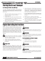
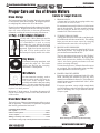
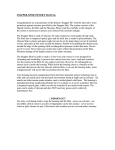
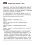
Read Operators Manual For Safety
PARTS MANUAL
&
Service Operations
FIGURE 1
PARKING BRAKE
DISENGAGED
FIGURE 3
LOCK OUT HUB
ENGAGED
FIGURE 2
PARKING BRAKE
ENGAGED
FIGURE 4
LOCK OUT HUB
DISENGAGED
FIGURE 5
WATER TANK
DRAIN
USA 1.800.428.3772
Intl. 1 .304.776.4231
WWW.TERRAMITE.COM/SAFETY
Copyright © 2007 Terramite Corporation
Charleston, WV/USA
2.1
Read Operators Manual For Safety
PARTS MANUAL
&
Service Operations
Storing the Street Sweeper
For Storage of More than 30 Days
To insure maximum performance and minimum
deterioration, the following procedures should be performed
when the Terramite Street Sweeper will be idle for more
than 30 days:
1. Wash the Terramite Street Sweeper and let dry
(waxing will help prevent paint oxidation).
2. Change engine oil.
3. Charge battery fully and disconnect the battery leads.
4. Fill fuel tank within 2 inches of filler neck (keeps out
condensation) and add fuel conditioner.
5. Squirt a small amount of oil into cylinders and crank
the engine over a few times.
6. Grease all pivot pins. Liberally apply cup grease to
all bare metal surfaces such as buckets and exposed
cylinder rods. Grease all pivot pins. Retract all
cylinder rods. Use WD40 on all electrical parts and
areas inaccessible to regular grease.
7. Set the Terramite Street Sweeper on stands so the
tires are off the ground. (Keeps tires from developing
flat spots.)
8. Deflate tires to 1/2 pressure to relax cords.
9. Use a protective such as Armor All® on hoses, seat
and tires to keep them from weathering
10. If the Terramite Street Sweeper is to be stored
outside, cover with a tarp or plastic cover to minimize
weathering.
Engine Operating Instructions
NOTE: With your Terramite Street Sweeper you will
receive an Operation and Service Folder for the particular
engine supplied with your machine. This manual contains
detailed information as to operation, maintenance and repair
of the engine and its various components. However, before
attempting any major repair of the engine, contact your
dealer or the factory as to whether it will affect your factory
warranty.
Before starting make sure that nobody is standing
in the immediate vicinity of the engine or driven machine.
1. ENGAGE PARKING BRAKE
2. CHECK THAT MACHINE IS IN NEUTRAL
3. CHECK THAT BROOM ROTATION IS IN OFF
POSITION
Engine Fuel
WARNING! Diesel fuel, although less explosive than
gasoline, is highly flammable, and its vapors can explode
under certain conditions. Store diesel fuel only in approved
containers in unoccupied buildings and away from sparks
or flames. Do not add diesel fuel while the engine is hot or
running, or start the engine near spilled fuel.
2.2
WARNING!
Do not activitate the starter for more than 20 seconds. If
the engine does not catch, wait one minute then try again.
WARNING!
If engine does not start after 2 attempts, refer to operation
manual supplied with the machine or call Terramite Service
Technicians for assistance.
Starting Kubota and Deutz Engines
1. Place key in ignition
2. Turn key clock wise to start position.
4. Release Key as soon as engine fires.
WARNING!
Do not activitate the starter for more than 20 seconds. If
the engine does not catch wait one minute then try again.
WARNING!
If engine does not start after 2 attempts, refer to operation
manual supplied with the machine or call Terramite Service
Technicians for assistance
WWW.TERRAMITE.COM/SAFETY
Charleston, WV/USA
Copyright © 2007 Terramite Corporation
USA 1.800.428.3772
Intl. 1 .304.776.4231
Read Operators Manual For Safety
PARTS MANUAL
&
Service Operations
Engine Operating Instructions (continued)
Do Not Use Ether as a Starting Aid
CAUTION!
The engine has a high compression ratio, and using ether
will ruin your engine. The damage will not be covered
under your warranty.
Total Failure of Starter
If the starter does not turn the engine over, shut off the
starter immediately. Do not make further attempts to start
the engine until the condition is corrected.
CAUTION!
Do not crank the engine continuously for more than 20
seconds at a time. If the engine does not start, allow a two
minute cool-down period between starting attempts. Failure
to follow these guidelines will burn out the starter motor.
If the engine develops sufficient speed to disengage the
starter but does not keep running (a “false start”), the engine
rotation must be allowed to come to a complete stop before
attempting to restart the engine, or engine damage may
result.
WARNING!
Do not tamper with the governor setting to increase the
maximum engine speed. Over-speeding is hazardous and
will void the warranty.
WARNING! Do not use JP4 Fuel or Ether
The minimum centane number 45 (Aviation fuel) JP4 or
either starting fluids must not be used.
Weather Considerations
Diesel Operation in Hot Weather
Below 10 Degrees
Operating the diesel engine in hot weather is mostly a
matter of keeping the coolant at the correct level, the
radiator clean and keeping an eye on the fan belt. Also, be
certain of the viscosity of lubricants.
Special procedures must be followed so your machine may
be readily started without damage. The hydraulic system
and the engine need to be fitted with electric heaters. The
machine can be warmed with a high output forced air
heater.
Temperatures Below 32 Degrees
There are several precautions which must be followed
when the temperature drops below 32 degrees Fahrenheit.
The oil in the engine and the hydraulic system needs to be
changed to winter weight and a new oil and air filter should
be considered. The battery should be kept at full charge.
As starting may be more difficult, be sure that you do not
run starter more than 20 seconds, followed by a two minute
cooling off period. Do not hit the outside of the casing of
the starter, as you may break the ceramic magnets.
Fuel Conditioner For Diesel Engines
Diesel fuel gets waxy at low temperatures and may not
flow through the filter and pump at the normal rate of flow.
Therefore, a good fuel conditioner additive is highly
recommended for temperatures below 32 degrees
Fahrenheit.
USA 1.800.428.3772
Intl. 1 .304.776.4231
WWW.TERRAMITE.COM/SAFETY
Copyright © 2007 Terramite Corporation
Charleston, WV/USA
2.3
Read Operators Manual For Safety
PARTS MANUAL
&
Service Operations
Periodic Service
General Considerations
REQUIRED MAINTENANCE
These required maintenance procedures should be
performed at the frequency stated in the table. They should
also be included as part of any seasonal tune-up. Perform
these maintenance procedures more frequently when the
engine is operated under extremely dusty or dirty conditions.
Although your Terramite Street Sweeper is made of the
finest and most durable materials, it will only hold up if
given proper care. The maintenance procedures are very
simple and easy to do. We have also included space in the
back of this handbook for keeping a service record of your
machine.
IMPORTANT: See attached New Machine First
Service Schedule for items that should be checked or
serviced during the first 4 to 50 hours.
Clean Air Intake Screen
Daily
Check Engine Oil Level
Daily
Check Hydraulic Oil Level
Daily
Check/Replace Fuel Filter**
As Required
Change Oil and Filter
As Specified
Clean Cooling Fins and
External Surfaces
50 hrs. or as required
**SEE ENGINE MAINTENANCE MANUAL
FREQUENCY
We also suggest that the air filter be checked weekly
in the event you are working in extremely dirty or dusty
conditions. The manufacturer’s air filter should be
used, or warranty may be denied. Otherwise, check
and clean monthly.
Engine Oil Service
Engine Oil (Recommended)
Changing the Engine Oil Filter
Refer to engine operating manual supplied with machine.
Your Diesel is equipped with an oil filter. Replace the oil
filter, in accordance with the “Oil Change Intervals” table.
Always use a genuine OEM oil filter and replace as follows:
Drain crankcase oil, then remove old filter. Before installing
replacement filter, apply a thin coating of clean oil on the
surface of the rubber seal. Turn filter clockwise until rubber
seal contacts the filter adapter, then tighten filter an
additional 2/3 to 3/4 turn. Add an additional 1/2 pint of oil
for the filter capacity. Start the engine and check for oil
leakage.
Checking Engine Oil
Before checking the oil, make sure the engine is stopped
and resting on a level surface. Also, make sure the engine
is cool and the oil has had time to drain into the sump.
Bring the level up to, but not over, the full mark on the dip
stick. Always check the level before adding more oil.
CAUTION: Do not operate the engine above or below
marked area on the dip stick.
Changing Engine Oil
For a new engine, change oil after the first 5 hours of
operation, after that every 100 hours (50 if multi-viscosity
oil is used). Drain oil while the engine is warm from
operation. The oil will flow freely and carry away more
impurities. Drain oil as follows: Remove the oil drain plug
and oil fill cap. Dispose of the oil in a manner that meets
Local, State and Federal regulations. Reinstall the drain
plug. Make sure it is tightened securely. Be sure the
engine is level when filling and checking oil. Then fill with
new oil to the top line on the dipstick. Refer to engine
operating manual for proper type. Always check the level
on the dipstick before adding more oil. Reinstalled the oil
fill cap and make sure it is tightened securely.
2.4
Extended Engine Oil Change Intervals
NOTICE: Using other than the proper class oil or
extending oil change intervals longer than recommended
will cause engine damage which is not covered by the
engine warranty.
Engine Air Filter (Paper Element)
The diesel engines are equipped with a high-density paper
air cleaner element. The paper element should be replaced
every 100 hours. Do not wash or use pressurized air to
clean the paper element. Before installing new filter, be
sure to inspect it for damage and that it fits perfectly when
replaced.
WWW.TERRAMITE.COM/SAFETY
Charleston, WV/USA
Copyright © 2007 Terramite Corporation
USA 1.800.428.3772
Intl. 1 .304.776.4231
Read Operators Manual For Safety
PARTS MANUAL
&
Service Operations
Hydraulic System Service
Check Hydraulic Oil Level Daily
Before checking the hydraulic oil sight gauge, all cylinders
should be retracted. The correct oil level is halfway up
the sight gauge. To avoid damage to the hydraulic pumps,
drain and replace milky-looking oil. Proceed as follows to
drain the oil out of the reservoir tank.
Hydraulic Oil Filter
When the machine is new, the system oil and filter should
be changed within the first 50 hours. After that, every 200
hours. Fill system with API SF/CD 10W below 40 degrees.
Oil should be changed on a level surface. It is
recommended that the oil be changed right after use while
the oil is warm.
Hydraulic Oil Leaks Can Be Dangerous
WARNING! As this may be your first experience with a
machine that functions primarily through hydraulic
pressure, never inspect or put your hands close to any part
of the hydraulic components of the machine while the
engine is running or within two minutes after being shut
down. If injured by escaping fluid, go to the emergency
room of the nearest hospital at once and tell them the nature
of the injury. If there is not a hospital in the vicinity, call a
physician. Serious infection or a reaction such as gangrene
can develop if proper medical treatment is not administered
immediately.
Minor Hydraulic Oil Leaks
Oil leaks are often difficult to locate, as oil may leak from
areas in the machine that are hidden from view. However,
if you can locate the leak, take a cloth and completely dry
everything around the leak to determine how fast the oil is
escaping. A drop of oil every 10 seconds is only 1/2 oz.
per hour. Do not use teflon tape to try to stop a leak, as it
can get loose in the system. You can easily over tighten a
fitting or hose wrapped with teflon, causing a housing to
crack. The preferred sealant is Loktite™ hydraulic thread
sealant with teflon paste.
DANGER! Oil and Fittings Get Hot
degrees. However, if the surface or hydraulic oil
temperatures exceed these temperatures, it may be caused
by having a control valve held open too long. Always return
control valve to neutral when not in use. It could also
indicate a low oil supply or contaminated oil. If low, refill.
If contaminated, drain and refill with new oil, and replace
filter. It could also indicate a kink or dent in a hose line or
a worn pump. (See Service Manual for Pump
replacement.)
NOTE: Always make sure major leaks are contained
and the oil disposed of in a proper manner. Stains on
concrete may be removed by applying a mixture of oil dry
and solvent. Let mixture set for a few hours before
removal. Dispose of according to applicable Local/State/
Federal Laws.
Changing the Hydraulic System Oil
1. Make sure all the cylinder rods are fully retracted.
2. Remove the sump line.
3. Remove the sump strainer, wash it in solvent, dry
thoroughly.
4. Replace in reverse order.
5. Fill the system with recommended oil until it reaches
the proper level.
NOTE: There is no need to bleed the hydraulic system,
the air will come out of the oil by itself. The machine may
vibrate for a few minutes until the air purges. Be sure to
dispose of your waste oil in a manner acceptable to Federal,
State and local authorities.
Some Tips on Hydraulic Hoses
Inspect hoses regularly for nicks, cuts and wear. There
are two wire braid layers under the rubber outer cover.
When wire is exposed but undamaged, the hose still may
be used, but should be replaced as soon as possible.
If You Need New Hydraulic Hoses or Parts
All hoses are JIC. Hoses may be obtained from Terramite
Corporation or any industrial rubber supplier or hydraulic
shop. Return the old hoses so they can match them. Short
hoses may be made from the good portion of a damaged
hose.
It is normal for the hydraulic oil to reach 170 degrees; and
the hydraulic hoses, cylinders and components, acting as a
large passive radiator, can reach temperatures of over 200
USA 1.800.428.3772
Intl. 1 .304.776.4231
WWW.TERRAMITE.COM/SAFETY
Copyright © 2007 Terramite Corporation
Charleston, WV/USA
2.5
Read Operators Manual For Safety
PARTS MANUAL
&
Service Operations
Street Sweeper Lubrication
Lubricating the Pivot Pins
The most important single thing you can do to increase the
life of the Terramite Street Sweeper is proper lubrication
of the pivot pins. The pivot pins should be lubricated with
a good lithium based grease every four hours of operation.
Wipe dirt from the fittings before greasing. Replace any
lost or damaged fittings immediately.
to your machine. An ungreased pin will rust. The next
time you use the machine the rust wears off, exposing
more metal, which also rusts. The rust and dirt make a
destructive grinding compound. Many people falsely blame
the manufacturer for their own neglect in lubricating the
machine. This is not covered under your warranty.
Use Caution when Replacing Pins
How to Ruin a Good Machine
The first 20 hours of use are critical to the life of the
machine. The pivot pins have minute edges which need
to be broken in just as an automobile engines need to be
broken in. If the pins are not adequately greased, they will
break their retainers and work out, possibly causing damage
When driving pivot pins in or out, use care to guard against
injury from particles that may chip off the pin or object
used in striking the pin. These pins can fly out at
considerable speed if they are not tapped lightly just before
they come out. Safety glassed must be worn.
Battery and Tires
Low Maintenance Battery
Avoid High Tire Pressure
Your Terramite Street Sweeper is equipped with a low
maintenance battery. It uses a special construction to
minimize water requirements. There is an “eye” on the
battery to determine the conditions.
Cold Weather Considerations
NOTE: Cold weather makes a marginal battery useless.
A battery fully charged at 80 deg. F. will have only 60% of
its capacity at 32 deg. F., and only 40% at zero. A halfcharged battery has only 32% at 32 deg. F and 21% at
zero.
CAUTION! Excessive tire pressures increase the
possibility of punctures and cause a rougher ride. The rim
or tire could blow out, causing extreme injury or even death!
Tire Traction and Hazards
Avoid excessive wheel spin when loading. On most
surfaces, wheel spin causes loss of traction and premature
wear out of tires. Watch for hazards such as nails, glass,
etc.
Tire Pressures and Rim Size
Titan - ST Radial 205/75R14
50PSI Cold -Load 1760 Lbs.
Paint and Cleaning
Protecting the Paint
Because it is highly resistant to nearly everything, it requires
little care. But constant exposure to sunlight will fade it
just as other paints eventually fade. A coat of wax will
help protect it. Leaving spilled diesel on your hood is not
only an unsafe practice, but will cause stains and will
2.6
inevitably eat through your paint. Small scratches should
be touched up or kept waxed to keep rust from attaching
the metal under the paint.
WWW.TERRAMITE.COM/SAFETY
Charleston, WV/USA
Copyright © 2007 Terramite Corporation
USA 1.800.428.3772
Intl. 1 .304.776.4231
Read Operators Manual For Safety
PARTS MANUAL
&
Service Operations
Paint and Cleaning (continued)
Paint Cleaning Solutions
Fasteners (Nuts and Bolts)
Some cleaning solutions and solvents used in high pressure
washers may bleach the finish if used in high concentration
or not rinsed from the machine. This can be avoided by
diluting the cleaning solution or not letting it set too long.
It is particularly important to check all nuts and bolts for
tightness after the first 5 hours of use. All drive train bolts
should receive extra attention. Thereafter, check every
250 hours.
Trouble Shooting
If a particular difficulty is experienced, check the symptoms
listed below. Possible causes and remedies are given for
each symptom. If the trouble is not corrected after
following the suggested solution, call your dealer or call
Terramite Corporation.
Total Failure of Hydraulic Power
(Engine is running, but nothing works)
Stripped engine to transmission coupling. Must be replaced.
Loss of Tram Power
The hubs may be disengaged for towing. This will cause
loss of tram power.
This may indicate a worn transmission. Check with factory
technician
Loss of Sweeping Power
Check for:
1. Low hydraulic oil.
2. Collapsed hose (hose can collapse internally, not
showing any visible signs.)
3. Worn Pump. Check pump pressure.
4. Internal Valve leakage. Valves will sometimes
develope leaks between the spools, yet not leak
outside. Switching hoses to another valve will
determine whether the valve section is bad.
5. Broken or weak relief valve. Check pressure. Check
for fatigued or broken relief valve spring. All
cylinders will lack power. You will have a little more
power when your machine is cold. A weakened
spring will lose power so gradually that you may not
notice the decline in power until it seriously affects
the machine performance. A broken spring will cause
a sudden drop in cylinder power.
USA 1.800.428.3772
Intl. 1 .304.776.4231
Sluggish and Slow Operation
Oil still cold. Pump badly worn or damaged. Restriction
in suction line. Clogged oil filter or sump strainer.
Control Valve Sticks or Works Hard
Normally, this is a problem for your dealer's service
department. It is usually dirty valves, tie bolts too tight or
float detent position adjusted too tight.
Street Sweeper Doesn't Move in Either
Direction
If this happened over a period of time, the transmission is
totally worn out. If it happened instantly, check for the
following:
1. Make sure rear lock-outs are in.
2. Foot pedal disconnected.
3. Bolts broken on coupling.
Transmission/Pump Makes Noise
First check the oil viscosity. If too high, replace with
specified oil. Then look for a kink or dent in oil lines. If
not of these, it may be air in the system. See your dealer.
Erratic Motion
1. Retract all rods and check hydraulic oil level.
2. Broken or weak pedal spring.
3. Worn transmission.
Hydraulic Oil Foams
1.
2.
3.
4.
5.
Low oil supply.
Air leak in line from reservoir to pump.
Incorrect hydraulic oil.
Blocked valve restrictor.
Check sump hose for tightness.
WWW.TERRAMITE.COM/SAFETY
Copyright © 2007 Terramite Corporation
Charleston, WV/USA
2.7
Read Operators Manual For Safety
PARTS MANUAL
&
Service Operations
Trouble Shooting (continued)
Hydraulic Oil Heats
1. Low oil supply.
2. Contaminated oil.
3. Control valve held open too long.
None of the Problems Listed
If the problem involves a part of the machine, such as the
engine, transmission, hydraulic pump, etc., that is
manufactured by someone other than Terramite Corporation,
first check your service manual for more detailed information.
If you do not find it there, contact your dealer or the original
manufacturer's service department. For dealer locations,
call Terramite Corporation at 1-800-428-3772 or International
1-304-776-4231.
Wheel Drive Slow or Will Not Go
1. Drive motor seal failure may be checked by removing
the plug on the rear wheel lock out. If there is any
oil present the motor shaft seal has failed.
2. Check hydraulic pressure of transmission.
Broom Rotation Stops or is Slow
1. Check Gear pump pressure using a portable hydraulic
test box, test the GPM and PSI with the engine RPM
at full throttle, the Gear Pump should produce from
9-1/2 to 10-1/2 GPM at 3,000 PSI.
2. To check broom motors individually, disconnect the
2 hoses to the motor and plug the hoses with steel
caps. Install a jumper hose between the ports to
eliminate leakage.
3. If the broom motor is not able to run the broom,
remove the broom motor and make sure the square
key on the broom motor shaft has not sheared.
Setting the Auxiliary Hydraulic System Main
Relief Valve
1. Install a 5,000 lb. pressure oil filled gauge in the outlet
port of the relief valve.
2. Start the engine and set the throttle at full. Slowly
turn the adjustment screw in (turn clockwise) until a
consistent pressure of 3,000 PSI is reached. Lock
down the lock nut and install the acorn cap on the
screw and recheck the pressure.
Main Pump Output Testing
Use a hydraulic pressure gauge and a flow meter that
measures both flow (GPM) and pressure (PSI). The
transmission pump will produce 15 GPM and approximately
3,500 PSI with the engine set at full throttle.
Machine Operation Control Location
Purpose and Scope
ITEM
LOCATION
FUNCTION
1. Seat Belt
Left and right side of seat.
2. Parking/Emergency
Brake
Lever to left of seat.
3. Variable Speed
Forward and to the right of the right
foot position on the floorboard
4. F/R Valve Lever
Located to the right of the operator
seat.
To prevent operator from falling off
machine.
To hold machine from rolling when
parked and in neutral. To be used for
emergency stopping of machine.
Varies machine speed in forward and
reverse when F/R Valve handle is
actuated.
A. Forward position allows machine
to travel forward when variable
speed pedal is depressed (See
Item 4).
B. Center position hydrostatically
locks machine in park (be sure
to also set Parking Brake).
2.8
WWW.TERRAMITE.COM/SAFETY
Charleston, WV/USA
Copyright © 2007 Terramite Corporation
USA 1.800.428.3772
Intl. 1 .304.776.4231
Read Operators Manual For Safety
PARTS MANUAL
&
Service Operations
Machine Operation Control Location (continued)
ITEM
LOCATION
5. Keyswitch
Centrally located below the steering
wheel.
6. Broom Rotary
Located to the right of the steering
wheel.
7. Broom Left-To-Right
Located to left of and furthest
from the steering wheel.
8. Broom Lift Control
Located to left of and closest to
the steering wheel.
9. Engine Throttle
To right of and below the steering
wheel.
FUNCTION
C. Rear position allows unit to travel
in reverse when the variable speed
pedal is depressed (See Item 4).
Preheats engine glow plugs when
turned and held in full left position,
starts engine when turned and held in
full right position. 1st "Notch" positions
from full right is "Run", and 2nd
"Notch" position from full right is
"Off". (On Kubota ONLY)
When pushed forward broom sweeps
forward, when in center position,
broom stops. Variable speed rotation.
When pushed forward, right end of
broom moves towards rear when
pulled back, right end of broom moves
forward.
When pushed all the way forward and
locked into detented position, broom
head goes to lowered and operating
float position. When lever is pushed
forward broom head raises off of surface.
To set engine operating speed.
Lubrication and Maintenance Chart
ITEM
DESCRIPTION/LOCATION
MAINTENANCE SCHEDULE
1. Grease Fittings
a. (2) Bearing on Front Fork
b. (1) Variable-Speed-Pedal under
floorboard
c. (2) Left and Right on Brake Rod
d. (1) Foot Brake
Grease all fittings daily
2. Hydraulic Oil
With oil hot, oil level should be in
center of eye on side of hydraulic tank
and/or 1" below top of tank.
Capacity: 20 Gallons
Change Hydraulic Oil every 6
months or as needed.
3. Hydraulic Spin-On
Filters
a. 10 Micron Part #21002
2 under floorboard.
b. Hydraulic Tank Screen Part #38072
at rear of Hydraulic Tank.
c. High Pressure Filter Element
Part #38019 inside hood and to right
of engine.
Change both Spin-On filters every
3 months.
Remove and clean every 6 months.
USA 1.800.428.3772
Intl. 1 .304.776.4231
Change every 6 months.
WWW.TERRAMITE.COM/SAFETY
Copyright © 2007 Terramite Corporation
Charleston, WV/USA
2.9
Read Operators Manual For Safety
PARTS MANUAL
&
Service Operations
Lubrication and Maintenance Chart (continued)
ITEM
DESCRIPTION/LOCATION
MAINTENANCE SCHEDULE
4. Engine Oil
Engine Oil Type: Refer to Engine
Manufacturers Operations Manual.
Change Engine oil and all filters, air,
spin-on fuel, in-line fuel, and oil every
150 hours.
5. Radiator Water/Antifreeze
Strictly 50% water and 50% permanent
Antifreeze mixture only!!!!
Check mix and level. Level to be 1/2
full in plastic over-fill tank.
6. Tire Pressure
45 PSI to 50 PSI
Check Daily.
7. Water Filters
Under Floorboard, Water Tanks
Clean as Needed
8. Front Wheel Bearings
Front Wheel inside and outside.
Repack monthly.
9. Fuel Tank Drain
Pipe plug located in center of and
at bottom of fuel tank.
Drain once a year.
Between wheel and frame. Remove
female hex plug on front or back of
housing to check.
Capacity: 6 Ounces
Motor Oil: SW 30 Wt. Detergent
Check every 3 months.
10. Wheel Lock-Out
Oil Level
Service and Maintenance Points
All references to "Left" or "Right" side of the Terramite
Street Sweeper are stated as from the Operators seat
facing forward.
Anti-Freeze Mix
Liquid cooled engines are very sensitive to the water/
antifreeze mix. To much of either water or antifreeze will
cause engine overheating. The proper mix is 50% water
and 50% antifreeze.
Air cooled engines have no need for anti-freeze.
Machine Trouble Shooting & Hydraulic Component
Check-Out
Before testing any hydraulic component always check the
hydraulic oil level. Bring the hydraulic oil temperature up
to 20° over Ambient. Place the machine on a flat surface.
2.10
The hydraulic oil level should be in center of the "Eye"
indicator and/or not more than 1" below the top surface of
hydraulic oil tank.
WWW.TERRAMITE.COM/SAFETY
Charleston, WV/USA
Copyright © 2007 Terramite Corporation
USA 1.800.428.3772
Intl. 1 .304.776.4231
Read Operators Manual For Safety
PARTS MANUAL
&
Service Operations
Proper Care and Use of Broom Wafers
Factors for Longer Brush Life.
Broom Storage
The broom portion of the Terramite Street Sweeper should
be stored away from direct sunlight. Prolonged exposure
to sunlight greatly reduces the life of the bristles.
Do not leave broom head lowered with weight on the bristles
when not in use. Weight on the bristles for long periods of
time will cause the bristles to become permanently
deformed, resulting in lowered sweeping effectiveness.
1/2 Poly - 1/2 Wire Wafers (Standard)
1/2 Poly and 1/2 Wire Wafers are used for
varying sweeping conditions. The 1/2 and
1/2 combination is used to sweep
throughout the year without changing
cores. This combination is the most used
approach. Eight foot brooms require 24
poly and 23 wire wafers and six foot
brooms require 19 poly and 18 wire wafers
Poly Wafers
For normal sweeping operations, such
as sand, dirt, paper, etc. This wafer
will be the best for dry sweeping.
Maximum 3" brush pattern.
Wire Wafers
For hard material sweeping, such as
concrete curing, mud, rock, snow, etc.
This wafer is the strongest wafer
available and with the sharpest cutting
force. For snow usage the ends pierce
the snow and ice quicker than poly wafers. This quickness
requires less down pressure.
Maximum 3" brush pattern. Exceeding this pattern will
lead to wire breakage, excessive wire wear, and short life
of the wafers.
1. BROOM LEVEL
A broom not level with the sweeping surface may
cut wafer life in excess of 50%.
For maximum broom wafer life the level of the broom
must be checked daily. The time spend in checking
and correcting the broom level will pay in the
extended life of the broom wafers.
2. TURNING BROOM CORE
Turning the broom core from end to end during the
life of the brush will also extend its life. This turning
helps prevent uneven wear caused by sweeping
material from the same side, refer to page 2.17.
3. BRUSH DOWN PRESSURE
The most common reason for short brush life is too
much down pressure. By using the proper amount
you can obtain maximum brush life.
The best sweeping action occurs by the "flicking"
action of the bristles at their tips. By applying too
much down pressure the bristles are using their
"sides", this action greatly accelerates wear and
reduces sweeping efficiency.
To limit down pressure, Terramite Street Sweepers
are equipped with an adjustable spring assembly.
Proper adjustment is shown in Figure 1.
4. PROPER GROUND SPEED
Proper ground speed is important for the life of the
brush. Running the machine too fast may allow
material to accumulate in front of it. This build up of
material creates pressure on the bristle "sides", which
leads to their "wear".
For proper operation, sweep at high enough brush
speed to discharge material and with proper ground
speed to discharge the swept material from the
sweepers path.
Brush Wafer Wear Life
The brush is one of the most important parts of the sweeper
and its operations. The brush is a replaceable component
that literally performs the hard work.
EXAMPLE OF WEAR LIFE
Fine Asphalt ............................................................................. 1 Year
Finish Coated Asphalt ............................................................ 6 Mos.
1st Pass Asphalt ................................................................. 3-4 Mons.
Milling (Ground up road surface) ....................................... 1 week
These number will be greatly reduced if used in an incorrect manner.
USA 1.800.428.3772
Intl. 1 .304.776.4231
RIGHT
WRONG
FIGURE 1
Brush Setting Decal and Proper Brush Setting
WWW.TERRAMITE.COM/SAFETY
Copyright © 2007 Terramite Corporation
Charleston, WV/USA
2.11
Read Operators Manual For Safety
PARTS MANUAL
&
Service Operations
Broom Core Removal/Wafer Replacement
1.
2.
3.
4.
5.
6.
7.
8.
9.
10.
11.
Place sweeper in level spot.
Engage parking brake
Turn off engine.
Clean the broom head.
Lower the sweeper head until the bristles just touch
the surface.
Remove the 3 bolts (Shown as “A” in Figure 1).
Remove the bolt (Shown as “B” in Figure 1).
Pull the motor assembly from the brush core and lay
it to the side. DO NOT REMOVE ANY HOSES!
Start the sweeper at low idle. Raise the broom head
enough to allow the core to be completely removed.
Turn off engine.
If turning the broom for brush life, rotate broom core
and skip to step. 16.
Remove the (2) screws and cap plate (Shown as
“A” in Figure 2).
A
A
B
FIGURE 1
FIGURE 2
FIGURE 5
Proper Placement
of Wafers on Core
FIGURE 4
Improper Placement
of Drive Pins (Circled)
2.12
12. Remove wafers.
13. Place a wafer onto the core with the drive pins
between the tube (Shown in Figure 3 for proper
placement and Figure 4 for improper placement).
14. The next wafer is flipped as it is placed over the
core and rotated 1/3 turn (Shown in Figure 4 for
proper placement and Figure 5 for improper
placement).
NOTE: To have proper number of wafers it may
be necessary to tap them with a heavy rubber
hammer.
NOTE: For 1/2 wire and 1/2 poly place a poly wafer
on each end.
15. Reattach the end cap.
16. Place broom core into broom head.
17. Reattach the motor assembly.
18. Check for proper operation.
WWW.TERRAMITE.COM/SAFETY
Charleston, WV/USA
Copyright © 2007 Terramite Corporation
FIGURE 3
Proper Placement
of Drive Pins (Circled)
FIGURE 6
Improper Placement
of Wafers on Core
USA 1.800.428.3772
Intl. 1 .304.776.4231
Read Operators Manual For Safety
PARTS MANUAL
&
Service Operations
Setting and Adjusting Broom
1. Set the broom angle to that needed. (See Figures 1,
2 and 3).
2. Set broom level. (See Figure 4). Loosen the 3/4
lock nuts. (See Figure 5). Raise or lower broom
TOP
VIEW
motor to obtain consistant brush contact across full
length of the broom.
3. Adjust broom contact. (See Figure 6).
TOP
VIEW
FIGURE 1
Angled Right
TOP
VIEW
FIGURE 2
Angled Left
FIGURE 4
Horizontal Level
FIGURE 3
Straight
FIGURE 5
Lock Nut - Left Side (Circled)
RIGHT
WRONG
FIGURE 6 - Brush Setting Decal and Example of Proper Brush Setting
USA 1.800.428.3772
Intl. 1 .304.776.4231
WWW.TERRAMITE.COM/SAFETY
Copyright © 2007 Terramite Corporation
Charleston, WV/USA
2.13