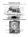
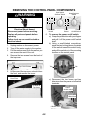
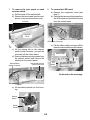
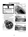
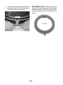
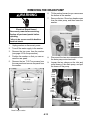
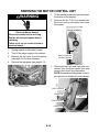
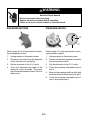
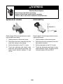
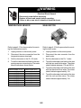
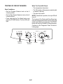
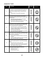
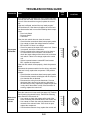
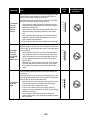
1
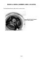
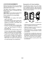
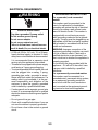
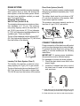
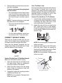
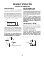
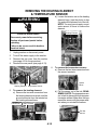
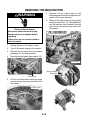
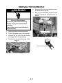
CONSUMER SERVICES TECHNICAL EDUCATION GROUP PRESENTS L-75 24″ FRONT-LOADING AUTOMATIC WASHER Model LHW0050PQ JOB AID Part No. 8178474 FORWARD This Whirlpool Job Aid “24″ Front-Loading Automatic Washer” (Part No. 8178474), provides the technician with information on the installation, operation, and service of the 24″ Front-Loading Automatic Washer. It is to be used as a training Job Aid and Service Manual. For specific information on the model being serviced, refer to the “Use and Care Guide,” or “Tech Sheet” provided with the washer. The Wiring Diagram used in this Job Aid is typical and should be used for training purposes only. Always use the Wiring Diagram supplied with the product when servicing the unit. GOALS AND OBJECTIVES The goal of this Job Aid is to provide detailed information that will enable the service technician to properly diagnose malfunctions and repair the 24″ Front-Loading Automatic Washer. The objectives of this Job Aid are to: • • • • Understand and follow proper safety precautions. Successfully troubleshoot and diagnose malfunctions. Successfully perform necessary repairs. Successfully return the washer to its proper operational status. WHIRLPOOL CORPORATION assumes no responsibility for any repairs made on our products by anyone other than Authorized Service Technicians. Copyright © 2004, Whirlpool Corporation, Benton Harbor, MI 49022 - ii - TABLE OF CONTENTS Page GENERAL ............................................................................................................................... 1-1 Safety First ......................................................................................................................... 1-1 Model & Serial Number Label Location ............................................................................. 1-2 Specifications ..................................................................................................................... 1-3 Whirlpool Washer Warranty ............................................................................................... 1-4 INSTALLATION INFORMATION ........................................................................................... 2-1 Installation Requirements .................................................................................................. 2-1 Installation Instructions ...................................................................................................... 2-4 PRODUCT OPERATION ........................................................................................................ 3-1 Theory Of Operation .......................................................................................................... 3-1 Washer Use ....................................................................................................................... 3-3 Washer Care ...................................................................................................................... 3-8 COMPONENT ACCESS ......................................................................................................... 4-1 Component Locations ........................................................................................................ 4-1 Removing The Control Panel Components ....................................................................... 4-2 Removing A Dispenser Motor And The Dispenser Assembly ........................................... 4-5 Removing The Control Board & Pressure Switch .............................................................. 4-7 Removing A Water Inlet Valve ........................................................................................... 4-8 Removing The Power Supply Cord & Interference Filter ................................................... 4-9 Removing The Door Switch ............................................................................................. 4-10 Removing The Door Seal ................................................................................................ 4-11 Removing The Drain Pump ............................................................................................. 4-13 Removing The Motor Control Unit ................................................................................... 4-14 Removing The Heating Element & Temperature Sensor ................................................ 4-15 Removing The Wash Motor ............................................................................................. 4-16 Removing The Thermostat .............................................................................................. 4-17 Removing The Filter Housing .......................................................................................... 4-18 Removing The Basket From The Tub .............................................................................. 4-19 COMPONENT TESTING ........................................................................................................ 5-1 Power On/Off Switch ......................................................................................................... 5-1 Dispenser Motors ............................................................................................................... 5-2 Pressure Switch ................................................................................................................. 5-2 Water Inlet Valves .............................................................................................................. 5-3 Door Switch ....................................................................................................................... 5-3 Drain Pump ........................................................................................................................ 5-4 Heating Element ................................................................................................................ 5-4 Temperature Sensor .......................................................................................................... 5-5 Wash Motor ....................................................................................................................... 5-5 Thermostat ......................................................................................................................... 5-6 DIAGNOSTICS & TROUBLESHOOTING .............................................................................. 6-1 Diagnostics ........................................................................................................................ 6-1 Troubleshooting Guide ...................................................................................................... 6-4 Pinouts ............................................................................................................................... 6-7 WIRING DIAGRAM ................................................................................................................. 7-1 - iii - — NOTES — - iv - GENERAL SAFETY FIRST Your safety and the safety of others is very important. We have provided many important safety messages in this Job Aid and on the appliance. Always read and obey all safety messages. This is the safety alert symbol. This symbol alerts you to hazards that can kill or hurt you and others. All safety messages will follow the safety alert symbol and either the word “DANGER” or “WARNING.” These words mean: DANGER You can be killed or seriously injured if you don’t immediately follow instructions. WARNING You can be killed or seriously injured if you don’t follow instructions. All safety messages will tell you what the potential hazard is, tell you how to reduce the chance of injury, and tell you what can happen if the instructions are not followed. 1-1 MODEL & SERIAL NUMBER LABEL LOCATION The Model/Serial Number label location is shown below. Model & Serial Number Label Location 1-2 SPECIFICATIONS DIMENSIONS Height ................................................................................................... 33-1/4″ (84.45 cm) Width .................................................................................................... 23-3/8″ (59.37 cm) Depth .................................................................................................... 23-1/8″ (58.74 cm) Depth With Door Open ......................................................................... 38-3/4″ (98.42 cm) ELECTRICAL Voltage .................................................................................................... 120 VAC, 60 HZ Fuse ..................................................................................................................... 15 amps Heating Element Rating .................................................................................. 1150 Watts Drain Pump Rating .............................................................................................. 30 Watts MISCELLANEOUS Basket Volume .................................................................................... 2.5 cu. ft. (65 liters) Spin Speed ..............................................................550 rpm, Slow; 1200 rpm, Extra High 1-3 WHIRLPOOL WASHER WARRANTY ONE-YEAR FULL WARRANTY For one year from the date of purchase, when this washer is operated and maintained according to instructions attached to or furnished with the product, Whirlpool Corporation will pay for FSP replacement parts and repair labor costs to correct defects in materials or workmanship. Service must be provided by a Whirlpool designated service company. SECOND YEAR LIMITED WARRANTY ON ALL ELECTRONIC CONTROL BOARDS For the second year from the date of purchase, when this washer is operated and maintained according to instructions attached to or furnished with the product, Whirlpool Corporation will pay for FSP replacement parts for all electronic control boards. SECOND THROUGH FIFTH YEAR LIMITED WARRANTY ON DRIVE SYSTEM BELT & PULLEYS In the second through fifth years from the date of purchase, when this washer is operated and maintained according to instructions attached to or furnished with the product, Whirlpool Corporation will pay for FSP replacement parts for the following, if defective in materials or workmanship: drive system belt and pulleys. SECOND THROUGH TENTH YEAR LIMITED WARRANTY ON OUTER TUB In the second through tenth years from the date of purchase, when this washer is operated and maintained according to instructions attached to or furnished with the product, Whirlpool Corporation will pay for FSP replacement parts for the outer tub should it crack or fail to contain water, if defective in materials or workmanship. LIFETIME LIMITED WARRANTY ON STAINLESS STEEL WASH DRUM For the lifetime of the washer, when this washer is operated and maintained according to instructions attached to or furnished with the product, Whirlpool Corporation will pay for FSP replacement parts for the Stainless Steel wash drum if defective in materials or workmanship. Whirlpool Corporation will not pay for: 1. Service calls to correct the installation of your washer, to instruct you how to use your washer, or to replace house fuses or correct house wiring or plumbing. 2. Repairs when your washer is used in other than normal, single-family household use. 3. Damage resulting from accident, alteration, misuse, abuse, fire, flood, acts of God, improper installation, installation not in accordance with local electrical and plumbing codes, or use of products not approved by Whirlpool Corporation or Whirlpool Canada Inc. 4. Any labor costs during the limited warranty periods. 5. Replacement parts or repair labor costs for units operated outside the United States and Canada. 6. Pickup and delivery. This product is designed to be repaired in the home. 7. Repairs to parts or systems resulting from unauthorized modifications made to the appliance. 8. In Canada, travel or transportation expenses for customers who reside in remote areas. WHIRLPOOL CORPORATION AND WHIRLPOOL CANADA INC. SHALL NOT BE LIABLE FOR INCIDENTAL OR CONSEQUENTIAL DAMAGES. Some states and provinces do not allow the exclusion or limitation of incidental or consequential damages, so this exclusion or limitation may not apply to you. This warranty gives you specific legal rights and you may also have other rights which vary from state to state or province to province. Outside the 50 United States and Canada, this warranty does not apply. Contact your authorized Whirlpool dealer to determine if another warranty applies. If you need service, first see “Troubleshooting” in the “Use & Care Guide.” Additional help can be found by checking “Assistance or Service,” or call our Customer Interaction Center at 1-800-253-1301 from anywhere in the U.S.A. or write: Whirlpool Corporation, Customer Interaction Center, 553 Benson Road, Benton Harbor, Ml 49022-2692. In Canada, call Whirlpool Canada Inc. at 1-800-807-6777. 1-4 INSTALLATION INFORMATION INSTALLATION REQUIREMENTS Alternate Parts TOOLS AND PARTS Gather the required tools and parts before starting installation. The parts supplied are in the washer basket. Tools Needed Pliers that open to 1-9/16″ (3.95 cm) Flashlight (optional) Adjustable or open end wrench 9/16″ (14 mm) Level Wood block Utility knife Measuring tape Torx 20 screwdriver Phillips screwdriver Parts Supplied A B C D E A. U-shaped hose form B. Water inlet hoses (2) C. Inlet hose washer (2) D. Inlet hose washer/screen (2) E. Clear plastic plug F. Black plastic plug (2) F If You Have: You Will Need to Buy: Laundry tub or standpipe taller than 35″ (89 cm) Sump pump system (if not already available) 1″ (2.5 cm) diameter standpipe 2″ (5 cm) diameter to 1″ (2.5 cm) diameter standpipe adapter, Part #3363920 Overhead sewer Standard 20 gal. (76 L) 35″ (89 cm) tall drain tub or utility sink, sump pump and connectors (available from local plumbing suppliers) Floor drain Siphon break, Part #285320; additional drain hose, Part #3357090 and connector kit, Part #285442 Drain hose too short Drain hose, Part #388423 and hose kit, Part #285442 Drain hose too long Hose kit, Part #285442 Lint clogged drain Drain protector, Part #367031 Water faucets beyond reach of fill hoses 2 longer water fill hoses: 6 ft (1.8 m) Part #76314 10 ft (3.0 m) Part #350008 Installing new water inlet hoses British to universal hose adapter, Part #3357451 2-1 LOCATION REQUIREMENTS Recessed Area Or Closet Installation The dimensions shown are for the recommended spacing allowed, except the closet door ventilation openings. The dimensions shown for the closet door ventilation openings are the minimum required. Selecting the proper location for your washer improves performance and minimizes noise and possible washer “walk.” The washer can be installed in a basement, laundry room, closet, or recessed area (see “Drain System”). IMPORTANT: Do not install or store the washer where it will be exposed to the weather. Proper installation is your responsibility. You Will Need • A water heater set to deliver 120°F (49°C) water to the washer. • A grounded electrical outlet located within 5 ft (1.5 m) of where the power cord is attached to the back of the washer (see “Electrical Requirements”). • Hot and cold water faucets located within 3-1/2 ft (1.1 m) of the hot and cold water fill valves, and water pressure of 5-100 psi (34.5-690 kPa). • A level floor with a maximum slope of 3/4″ (1.9 cm) under entire washer. Installing the washer on carpeting is not recommended. • A sturdy floor to support the washer weight (washer, water and load) of 260 lbs (118 kg). 23-3/8" 23-1/8" (59.37 cm) (58.74 cm) Front View Side View Closet Door With Vents • Additional spacing should be considered for ease of installation and servicing. • Additional clearances may be required for wall, door and floor moldings. • Additional spacing of 1″ (2.5 cm) on all sides of the washer is recommended to reduce noise transfer. • If a closet door is installed, the minimum air openings in the top and bottom of the door are required. Louvered doors with air openings in the top and bottom are acceptable. • Companion appliance spacing should also be considered. • Do not store or operate your washer in temperatures at or below 38°F (3.33°C). Some water can remain in the washer and can cause damage in low temperatures. 2-2 ELECTRICAL REQUIREMENTS WARNING GROUNDING INSTRUCTIONS For a grounded, cord-connected washer: This washer must be grounded. In the event of a malfunction or breakdown, grounding will reduce the risk of electrical shock by providing a path of least resistance for electric current. This washer is equipped with a cord having an equipment-grounding conductor and a grounding plug. The plug must be plugged into an appropriate outlet that is properly installed and grounded in accordance with all local codes and ordinances. WARNING: Improper connection of the equipment-grounding conductor can result in a risk of electric shock. Check with a qualified electrician or serviceman if you are in doubt as to whether the appliance is properly grounded. Do not modify the plug provided with the appliance – if it will not fit the outlet, have a proper outlet installed by a qualified electrician. For a permanently connected washer: This washer must be connected to a grounded metal, permanent wiring system, or an equipment grounding conductor must be run with the circuit conductors and connected to the equipment-grounding terminal or lead on the appliance. Electrical Shock Hazard Plug into a grounded 3 prong outlet. Do not remove ground prong. Do not use an adapter. Do not use an extension cord. Failure to follow these instructions can result in death, fire, or electrical shock. • A 120-volt, 60-Hz., AC-only, 15- or 20-amp, fused electrical supply is required. A timedelay fuse or circuit breaker is recommended. It is recommended that a separate circuit serving only this appliance be provided. • This washer is equipped with a power supply cord having a 3 prong grounding plug. • To minimize possible shock hazard, the cord must be plugged into a mating, 3 prong, grounding-type outlet, grounded in accordance with local codes and ordinances. If a mating outlet is not available, it is the personal responsibility and obligation of the customer to have the properly grounded outlet installed by a qualified electrician. • If codes permit and a separate ground wire is used, it is recommended that a qualified electrician determine that the ground path is adequate. • Do not ground to a gas pipe. • Check with a qualified electrician if you are not sure the washer is properly grounded. • Do not have a fuse in the neutral or ground circuit. 2-3 INSTALLATION INSTRUCTIONS 3. WARNING Excessive Weight Hazard Use two or more people to move and install washer. Failure to do so can result in back or other injury. • To prevent floor damage, set the washer onto cardboard before moving across floor. • Move the washer to within approximately 3 ft (90 cm) of the final location. Next, loosen the two locking screws “A” and remove the two bars “B,” as illustrated below. Keep the bolts, screws, spacers and bars for future use. A REMOVE TRANSPORT SYSTEM B To install the machine, follow the steps below: 1. Move the machine to its installation position and remove the outer wrapping and the polystyrene base. 2. For transport reasons, the drum is locked in position. Loosen the four locking bolts and remove them along with the plastic spacers. A B C A. Screw (2) B. Transit Bar (2) 4. Plug the holes with the 4 clear plastic plugs and 2 black plastic plugs, packed inside the parts bag. D E A. Splined spacer (4) B. Spacer (4) C. Washer (4) NOTE: If the washer is to be transported at a later date, call your local service center. D. Transit bolt (4) E. Screw (2) NOTE: If the plastic spacers cannot be removed from the machine, open the side panel by loosening the screws indicated as “E” above. Remove the spacers and replace the panel. 2-4 DRAIN SYSTEM The washer can be installed using the standpipe drain system (floor or wall), the laundry tub drain system, or the floor drain system. Select the drain hose installation method you need (see “Tools and Parts”). Standpipe Drain System Wall Or Floor (Views A & B) The standpipe drain requires a minimum diameter standpipe of 2″ (5 cm). The minimum carry-away capacity can be no less than 4.2 gal. (15.9 L) per minute. A 2″ (5 cm) diameter to 1″ (2.5 cm) diameter standpipe adapter kit is available (see “Tools and Parts”). The top of the standpipe must be at least 23.5″ (59.7 cm) high and no higher than 72″ (182.88 cm) from the bottom of the washer. Floor Drain System (View D) The floor drain system requires a siphon break that may be purchased separately (see “Tools and Parts”). The siphon break must be a minimum of 28″ (71 cm) from the bottom of the washer. Additional hoses might be needed. The minimum carry-away capacity can be no less than 4.2 gal. (15.9 L) per minute. CONNECT DRAIN HOSE 23.5 - 35" (59.7 - 88.9 cm) A B Laundry Tub Drain System (View C) The laundry tub requires a minimum carryaway capacity of 4.2 gal. (15.9 L) per minute. The top of the laundry tub must be at least 23.5″ (59.7 cm) above the floor and no higher than 72″ (182.88 cm) from the bottom of the washer. Proper connection of the drain hose will protect your floors from damage due to water leakage. To prevent the drain hose from coming off or leaking, it must be installed per the following instructions. IMPORTANT: To ensure proper installation, this procedure must be followed exactly. For standpipe or laundry tub drain systems: 1. Check the drain hose to see that it is the proper length. 2. Install the U-shaped hose form to end of the drain hose to create a hook-shaped end; as shown. A B A. Snap either end of the U-shaped hose form to the drain hose at the point where the corrugation begins. B. Bend drain hose over the form and snap into place. 2-5 3. Clear The Water Lines Run water through both faucets and inlet hoses, into a bucket or laundry tub, to get rid of particles in the water lines that might clog the inlet filter washers. The water should be clean, especially where the system is new or has been left unused for a length of time. Connect The Inlet Hoses To The Washer 1. Insert the filter washer (supplied) into the coupling of the hose fitting elbow, before connecting the water inlet hose to the valve on the back of the washer. 2. Attach the hose with the red stripe to the HOT (right) inlet valve on the washer. Screw on coupling by hand until it is seated on the washer. Make sure the hose connection is tight. Place hooked end of drain hose into laundry tub or standpipe. To prevent drain water from going back into the washer: • Do not straighten hooked end of drain hose. Do not force excess drain hose into standpipe. Hose should be secure, but loose enough to provide a gap of air. NOTE: To prevent siphoning, do not seal the drain hose to the standpipe. • Do not lay excess drain hose in bottom of laundry tub. • For floor drain installation, see kit number required under “Tools and Parts.” CONNECT THE INLET HOSES There are two hoses provided with the machine. The hot water hose is indicated with a red stripe running the length of the hose. Insert new flat washers (supplied) into the straight hose fitting of each inlet hose. Firmly seat the washers in the couplings. A 3. B NOTE: Do not overtighten. Damage to the valves can result. Attach the other hose to the COLD water (left) inlet valve. Screw on coupling by hand until it is seated on the washer. Make sure the hose connection is tight. NOTE: Do not overtighten. Damage to the valves can result. A. Coupling B. Washer Connect The Inlet Hoses To The Water Faucets Make sure the washer basket is empty. 1. Attach the hose with the red stripe to the hot water faucet. Screw on coupling by hand until seated on the washer. 2. Attach the other hose to the cold water faucet. Screw on coupling by hand until seated on the washer. 3. Using pliers, tighten the couplings with an additional two-thirds turn. NOTE: Do not overtighten. Damage to the valves can result. B A A. Cold water inlet valve B. Hot water inlet valve 2-6 LEVEL THE WASHER Check For Leaks Turn on the water faucets and check for leaks. A small amount of water might enter the washer. You will drain this later. NOTE: Replace inlet hoses after 5 years of use to reduce the risk of hose failure. Record hose installation or replacement dates for future reference. Periodically inspect and replace hoses if bulges, kinks, cuts, wear, or leaks are found. Properly leveling your washer prevents excessive noise and vibration. 1. Move washer to final location. 2. Check that the washer is level. Check side to side and back to front by lining up the level, as shown in the following illustration. SECURE DRAIN HOSE 1. 2. 3. 4. Drape the power cord over the console. Move the washer to its final location and remove any cardboard used to move washer. Place the drain hose in the laundry tub or standpipe as shown (see illustrations A and B). If the washer faucets and the drain standpipe are recessed, place the hooked end of the drain hose in the standpipe as shown (see illustration C). 3. If the washer is not level, prop up the front of the washer with the wood block and adjust the feet up or down as necessary. If the washer is against a wall, move the washer out slightly before tipping back. Repeat this step until washer is level. COMPLETE THE INSTALLATION 1. A B C NOTE: • Do not force excess drain hose back into the rear of the washer. • To prevent siphoning, do not seal the drain hose into the standpipe. 2. 3. 4. 5. 2-7 Check the electrical requirements. Be sure that you have the correct electrical supply and the recommended grounding method (see “Electrical Requirements”). Check to be sure all parts are now installed. If there is an extra part, go back through the steps to see which step was skipped. Dispose of or recycle all packaging materials. Keep the shipping bolts, spacers, and transport bars for use if the washer should be transported. Check to be sure the water faucets are on. Check for leaks around faucets and inlet hoses. 6. 7. 8. WARNING Electrical Shock Hazard Plug into a grounded 3 prong outlet. Do not remove ground prong. Do not use an adapter. Do not use an extension cord. Failure to follow these instructions can result in death, fire, or electrical shock. 2-8 Plug into a grounded 3 prong outlet. Read “Washer Use.” To test your washer, measure and add 1/2 the normal recommended amount of High Efficiency (HE) detergent to the washer. Close the door. Select any cycle, and then press START. Allow it to complete one whole cycle. PRODUCT OPERATION THEORY OF OPERATION PRESSURE SWITCH HEATING ELEMENT AND TEMPERATURE SENSOR Various water levels will be used during different cycles. A single level pressure switch is utilized to determine the low water level setting. When the cycle requires the high or maximum water setting, the electronic control will calculate additional water levels, according to the type and quantity of load placed in the tub, and the cycle selected. These fill levels are based on time (see the following example). This washer utilizes a fused heating element to heat the water during certain cycles. A temperature sensor measures the water temperature, and sends a resistance value to the electronic control. In case of a failure in the heating element circuit, the electronic control will default to a maximum heating time of 30 minutes for each heating phase. After that default time, the washer will complete the program with the colder water. LEVEL (Liters) HIGHEST (15) HIGH (13) THE WATER INLET VALVES BASE (7.5) 40 70 80 There are two water inlet valves on the washer. Depending on the cycle and water temperature, the electronic control will energize either the hot or cold water valve solenoid, to produce the selected water temperature. TIME (seconds) Switch contacts P11 to P14 are used to determine the base water level. Should an overfill condition occur, contacts P11 to P16 will be made, shutting off the water supply, and signaling the electronic control to turn on the drain pump. P11 to P14 are also used to indicate to the electronic control that water is in the tub, allowing the heating element to be energized. THE DOOR LOCK SWITCH The door lock switch consists of a heater and bimetal. When a cycle starts, the heater is energized, which causes the bimetal to warp, and lock the door. Upon completion of the cycle, the heater de-energizes. After the bimetal cools, (up to two minutes), the door can be unlocked. P14 P12 BP1 P11 P16 HEATER BP3 Pressure Switch Contacts 3-1 BP2 DETERGENT DISPENSER ASSEMBLY Wax Motors The detergent dispenser is activated by two wax motors. During the Wash cycle, wax motor A is energized. This moves the diverter, inside the dispenser assembly, to flush the detergent cavity. During the Rinse cycle, wax motor B is energized, to perform the same function for the fabric softener. B A NOTE: There is no provision for, nor is it recommended, that the customer use bleach in this washer. 3-2 WASHER USE First Wash Cycle Without Laundry Before washing clothes for the first time, select the REGULAR/NORMAL cycle and run the washer without clothes. Use 1/2 the normal recommended amount of powdered or liquid High Efficiency (HE) detergent. This initial cycle serves to ensure the interior is clean before washing clothes. 1. To load washer: Open the washer door by pulling on the handle. Sort laundry according to color and type of fabric. Place a load of sorted clothes in the washer. Do not overload washer. Overloading can cause poor cleaning. • The washer can be fully loaded, but not tightly packed. Washer door should close easily. • Mix large and small items and avoid washing single items. Load evenly. • Wash small items, such as infant socks, in mesh garment bags. It is recommended that more than one garment bag be used, and that each garment bag be filled with equal amounts of material. • When unloading garments, occasionally check under the rubber rim at the front of the tub for small items. WARNING Fire Hazard Never place items in the washer that are dampened with gasoline or other flammable fluids. No washer can completely remove oil. Do not dry anything that has ever had any type of oil on it (including cooking oils). Doing so can result in death, explosion, or fire. STARTING THE WASHER WARNING: To reduce the risk of fire, electric shock, or injury to persons, read the IMPORTANT SAFETY INSTRUCTIONS in the “Use And Care Guide” before operating this appliance. The following is a guide to using your washer. Please refer to specific sections of the “Use And Care Guide” for more detailed information. Do not store laundry products on the top surface of this washer. Vibration is normal during operation. 2. Close the washer door by pushing it firmly until the lock clicks. The washer door will remain locked during the wash cycle. 3-3 3. Open the dispenser drawer and add laundry products to the detergent or fabric softener compartments. Close drawer slowly to avoid spills (see “Using the Dispenser”). IMPORTANT: To avoid damage to clothing, do not use liquid bleach or powdered color-safe bleach in this washer. If you need extra whitening, use a HE powder detergent with bleach additive. 4. 5. 6. NOTE: • For best performance, use High Efficiency detergents. The package for this type of detergent will be marked “HE” or “High Efficiency.” The wash action along with less water could create too much sudsing with a regular detergent. • Use only HE detergent made for frontloading washers and follow label instructions. The amount of detergent varies among the different brands, but for most detergents, you need only one or two tablespoons. Too much detergent could leave a residue on your clothes and possibly damage the appliance. • Do not add detergent to the Pre Wash compartment unless you have selected the Pre Wash option. If you have detergent in both the Pre Wash and Main Wash compartments, and have not selected a Pre Wash option, the washer could oversuds and spill onto the floor. • If you select the Pre Wash option, use powdered HE detergent in the Main Wash compartment. If you use liquid detergent in the Main Wash compartment, it will dispense immediately. • Excessive use of fabric softener can damage garments. • Close the detergent drawer securely. 7. IMPORTANT: To avoid water spillage, do not open the detergent drawer while the machine is operating. Turn on the washer by selecting POWER. Select one of the cycles by turning the cycle selector. The preset settings provide the recommended fabric care for the selected cycle. Select the desired options. Not all options are available with all cycles. To begin the wash cycle Select START. When the wash cycle is complete, the DONE status light glows, the door unlocks, and the wash load can be removed from the washer. To power down the washer manually after the wash cycle is complete, press POWER once. USING THE DISPENSER The washer has a dispenser drawer with three separate compartments for your laundry products. Two are for detergent, and one is for liquid fabric softener. Laundry products are diluted and dispensed automatically at the proper time during the wash cycle, making it unnecessary for you to return to the washer during the cycle to add them. It is normal for small amounts of water to remain in the dispensers when the wash cycle is complete. Do not add laundry additives directly into the wash tub. Always use the proper dispensers when adding laundry products. Choosing The Right Detergent For best washing performance, use a High Efficiency (HE), or low-sudsing, detergent. 3-4 To Fill Dispenser Compartments 1. Pull out the dispenser drawer. 2. Add the desired laundry product to the proper compartment. 3. Push in the dispenser drawer carefully and completely (to avoid spillage). Main Wash Detergent Compartment (Letter B in Dispenser Illustration) Add liquid or powdered detergent to this compartment for the main wash cycle. IMPORTANT: If you are using the Pre Wash option, powdered detergent must be used in the Main Wash compartment, since liquid detergents may seep out of the Main Wash compartment before the main wash begins. Do not fill beyond the “MAX” level. Pre Wash Detergent Compartment (Letter A in Dispenser Illustration) Add detergent to this compartment when using the Pre Wash option. Liquid or powdered detergent may be used in this compartment. The detergent will automatically be dispensed during Pre Wash if the Pre Wash option is selected. Using High Efficiency (HE) detergent, add 1/3 the recommended amount to the Pre Wash compartment and 2/3 the recommended amount to the Main Wash compartment. Fabric Softener Compartment (Letter D in Dispenser Illustration) Add 1/4 cup (60 mL) liquid fabric softener to this compartment. Fabric softener will be automatically dispensed in the final rinse. Do not fill beyond the “MAX” level. Dispenser A. Pre Wash detergent compartment B. Main Wash detergent compartment C. Dispenser release lever D. Fabric softener compartment 3-5 CONTROLS Status Lights As the program progresses, the light for the cycle in progress will glow. The Stop indicator light glows when the program is complete. At this point, there will be a 2 minute delay before the door lock will release and you can open the door. The control panel is simple to understand and easy to operate. The following photos define the knobs and buttons, and the paragraphs define the purpose of each. Power This button switches the power to the machine on and off. The button will glow to indicate the power is on and the Start button will flash. Spin Speed Knob Use this knob to set the spin speed. In addition to the Low, Medium, High and Extra High spin speeds, there is a No Spin option. This is for delicate fabrics that should not be spun dry. Cycle Knob Turn this knob to the desired program. The Cycle Chart (shown in the “Use And Care Guide”) defines each cycle in detail, so you can determine which program is best for each type of load. Extra Rinse Button This button sets the program to add one or two rinse cycles. The button will glow when this option is on. See “Cycles” (in the “Use And Care Guide”) for an explanation of the number of rinse cycles added to each cycle. Three rinses are usually sufficient, but if you live in an area with very soft water or you are allergic to detergent, you may want to use this option. This option is not available with Quick Wash or Spin. Stop Position If you turn the Cycle Knob to Stop, the program will be cancelled. There will be a 2 minute delay before the door lock will release and you can open the door. To restart the machine, you will have to reposition the Cycle Knob and press the Start Button. NOTE: Before the program will start, the machine will drain any water already in the machine. Before you press Start, it is a good idea to make sure you do not need to add more detergent. 3-6 Pre Wash Press this button to select a Pre Wash. This is recommended only for heavily soiled items. The button will glow when this option is on. If you use Pre Wash, be sure to put detergent in the Pre Wash compartment of the detergent drawer. NOTE: Pre Wash cannot be selected for the Hand Wash, Quick Wash and Spin cycles. Start Button After you have selected a cycle and options (Pre Wash or Extra Rinse), press this button to start the program. CYCLES The table below defines each wash cycle in detail to help you determine which cycle is best for each type of load. Options Available Cycles Heavy Soil (3) Whites Normal Color Heavy Soil (3) Normal Color Temp Hot Spin Fabrics Heavy Cottons, linens Cottons, linens, Heavy blends, synthetics Cottons, linens, Warm Heavy blends, synthetics Cottons, linens, Cold Light blends, synthetics Hot Cottons, linens, Heavy blends, synthetics Cottons, linens, Warm Light blends, synthetics Cottons, linens, Cold Light blends, synthetics Hot Hand Wash (4) Warm Quick Wash Soil Level Warm N/A Machine-washable Light wool, silk, nylon Machine-washable Light wool, silk, nylon Cottons, linens, N / A blends, synthetics Load Size Cycle Descriptions (1) REGULAR Long main wash, 3 rinses, Drain & Spin Main wash, 3 rinses, Drain Full & Spin Main wash, 3 rinses, Drain Full & Spin Main wash, 3 rinses, Drain Full & Spin SYNTHETICS Full Long main wash, 3 rinses, Drain & Spin Main wash, 3 rinses, Drain Half & Spin Main wash, 3 rinses, Drain Half & Spin DELICATE High-water level wash, 3 One-Third rinses, drain, gentle spin High-water level wash, 2 Full rinses, drain, gentle spin Half Full Drain and intensive spin Spin Speed (2) Pre Wash Extra Rinse Extra High Yes 2 Extra High Yes 2 Extra High Yes 2 Extra High Yes 2 Extra High Yes 1 Extra High Yes 1 Extra High Yes 1 Medium N/A 1 Medium N/A 1 Extra High N/A N/A NOTES: 1. For an explanation of the recommended load sizes, see “Loading” in the “Use and Care Guide.” 2. These are suggested spin speeds. 3. When you select the Heavy Soil cycle, the unit heats the water to 140°F (60°C) for the main wash. 4. The Hand Wash cycle has a maximum 800 rpm spin speed to eliminate stress on delicate fabrics. 3-7 WASHER CARE CLEANING THE WASHER 1. Place a pan or towel under the filter door, since a small amount of water could spill. WARNING: Before performing the operations described below, make sure that the power is off and the unit is unplugged. Cleaning The Exterior Use a soft damp cloth or sponge to wipe up any spills. Occasionally wipe the outside of the washer to keep it looking new. Use mild soap and water. Do not use abrasive products. 2. Remove the filter by rotating it a half-turn counterclockwise and pulling outwards. Cleaning The Interior Use a soft damp cloth or sponge to occasionally wipe the inner door to remove any detergent residue. Use mild soap and water. Do not use abrasive products. Cleaning The Door Seal Use a soft damp cloth or sponge when necessary. Check the fold of the seal periodically for any foreign objects. 3. Clean the filter with a soft brush under running water until all residue is removed. 4. Replace the filter and turn it clockwise until it is securely locked in place. Give the cap a gentle tug to confirm that the filter is in securely. Cleaning The Dispenser Drawer The dispenser drawer is removable for easy cleaning. 1. Unlock the dispenser drawer by pressing on the plastic part of the softener compartment marked “PUSH.” See “Using the Dispenser.” 2. Remove the drawer. 3. Do not clean the door with cleaning solvents or abrasive cleansers. You could damage the finish. 4. Replace the inserts and return the dispenser to the drawer. Cleaning The Control Panel To clean the control panel, use only a warm, damp cloth. NOTE: To prevent penetration of liquid into the door lock and electrical components: • Do not spray water or cleaning solvents on the control panel. • Do not use abrasive cleaners or scouring pads on the outer surfaces because they will scratch the finish and could remove the writing on the control panel. • Some paper towels may also scratch the finish. Cleaning The Lint Filter The lint filter should be cleaned about once a month. Make sure the washer has drained before opening the filter door. 3-8 COMPONENT ACCESS This section instructs you on how to service each component inside the Whirlpool Front-Loading Automatic Washer. The components and their locations are shown below. COMPONENT LOCATIONS Interference Filter Water Inlet Valves Power Supply Cord Pressure Switch Dispenser Motors Control Board Dispenser Assembly LED Board Spin Speed Selector Switch Pushbutton Board Wash Selector Switch Power On/Off Switch Door Seal Door Switch Basket & Tub Heating Element Thermostat Temperature Sensor Motor Control Unit Wash Motor Drain Pump Viewed From Rear Of Washer 4-1 REMOVING THE CONTROL PANEL COMPONENTS Spin Speed Selector Switch WARNING Electrical Shock Hazard Disconnect power before servicing. Replace all parts and panels before operating. Failure to do so can result in death or electrical shock. 1. 2. 3. 4. Pushbutton Board 6. Unplug washer or disconnect power. Turn off the water supply to the washer. Pull the washer away from the wall so you can access the rear of the unit. Remove the two screws from the back of the top cover. Top Cover Screws 5. Wash Selector Switch LED Board Power On/Off Switch To remove the power on/off switch: a) Grasp the pushbutton with your fingers and pull it off the power on/off switch shaft. b) Using a small-bladed screwdriver, press the two locking tabs on the sides of the switch toward the switch body, and pull the switch out of the mounting location on the control panel. Tab Tab Lift the rear of the top cover, unhook it from the front, and remove the cover. Unhook Top Cover From Front c) Disconnect the two brown and two blue wires from the power on/off switch terminals. Lift Rear Of Top Cover Power On/Off Switch 2 Blue Wires 2 Brown Wires 4-2 7. To remove the spin speed or wash selector switch: a) Pull the knob off the switch shaft. b) Remove the two screws from the component cover and remove the cover. 8. 2 Screws To remove the LED board: a) Remove the component cover (see step 7). b) Remove the two mounting screws from the LED board and remove the board from the control panel. Component Cover LED Board (2 Screws) c) Pull the ribbon cable connector off the board connector and remove the board. c) Lift the locking tab on the selector switch board connector, and pull the connector off the switch board. d) Remove the two mounting screws from the selector switch and remove the switch from the control panel. Wash Selector Switch Connector Ribbon Cable LED Board Spin Speed Selector Switch Connector Continued on the next page. 2 Screws 2 Screws e) Lift the selector switch out of its housing. Selector Switch Switch Housing 4-3 9. To remove the pushbutton board: a) Remove the component cover (see step 7). b) Remove the four mounting screws from the pushbutton board. c) Remove the board, board seal & holder, and pushbuttons from the control panel. d) Pull the two ribbon cable connectors off the board connectors and remove the board. Board Seal & Pushbuttons Pushbutton Board Ribbon Cables Pushbutton Board (4 Screws) 4-4 REMOVING A DISPENSER MOTOR AND THE DISPENSER ASSEMBLY 5. WARNING Dispenser Motors Electrical Shock Hazard Disconnect power before servicing. Replace all parts and panels before operating. Failure to do so can result in death or electrical shock. 1. 2. 3. 4. Unplug washer or disconnect power. Turn off the water supply to the washer. Remove the top cover from the washer (see page 4-2 for the procedure). To remove a dispenser motor: a) Remove the two wire connectors from the dispenser motor you are servicing. b) Lift the dispenser motor from the top of the dispenser and remove it. BK (Top) 2 OR (Bottom) To remove the dispenser assembly: a) Lift the two dispenser motors from the top of the dispenser (do not disconnect the wires) and move them out of the way. b) Pull the dispenser drawer out as far as the stop. Press down on the locking tab, pull the drawer out the rest of the way, and remove it. Locking Tab Dispenser Motors OR (Top) Dispenser Drawer BK (Bottom) Continued on the next page. 4-5 c) Remove the four screws from the front of the dispenser. e) Unhook the tub inlet hose from the dispenser tab, and pull the hose off the dispenser fitting. Dispenser Screws Unhook Tub Inlet Hose d) Loosen the clamps on the inlet and outlet hoses at the bottom rear of the dispenser, and pull the hoses off the dispenser. Outlet Hose Inlet Hose (From Water Fill Valves) Pull Hose Off Fitting Tub Inlet Hose f) Loosen the clamp on the tub inlet hose, pull the hose off the dispenser, and remove the dispenser assembly from the unit. 4-6 REMOVING THE CONTROL BOARD & PRESSURE SWITCH b) Disconnect the wire and ribbon cable connectors from the board. WARNING 10-Pin Connector 1-Pin Connector Electrical Shock Hazard Disconnect power before servicing. Replace all parts and panels before operating. Failure to do so can result in death or electrical shock. 1. 2. 3. 4. Ribbon Cable Edge Connectors 5. Unplug washer or disconnect power. Turn off the water supply to the washer. Remove the top cover from the washer (see page 4-2 for the procedure). To remove the control board: a) Press and unlock the two tabs from the right edge of the board, and remove the board from its holder. To remove the pressure switch: a) Disconnect the three wire connectors from the pressure switch terminals. b) Remove the mounting screw from the switch. Pressure Switch Screw Red 2 Black Gray c) Pull the pressure hose off the pressure switch fitting and remove the switch. Control Board Press Locking Tabs Pressure Hose 4-7 REMOVING A WATER INLET VALVE 4. WARNING Disconnect the wire connectors from the water inlet valve you are servicing. Red Wires Hot Water Inlet Valve Cold Water Inlet Valve Black Electrical Shock Hazard Disconnect power before servicing. Replace all parts and panels before operating. Failure to do so can result in death or electrical shock. 1. 2. 3. 2 Red Unplug washer or disconnect power. Turn off the water supply to the washer. Remove the top cover from the washer (see page 4-2 for the procedure). Water Inlet Valves 5. Remove the two T-20 Torx screws from the water inlet valve and remove the valve from the rear of the unit. Water Inlet Valve T-20 Torx Screws 4-8 REMOVING THE POWER SUPPLY CORD & INTERFERENCE FILTER c) Remove the screw from the power supply cord strain relief and open the clamp. d) Pull the power supply cord out of the strain relief. WARNING Strain Relief Screw Electrical Shock Hazard Disconnect power before servicing. Replace all parts and panels before operating. Failure to do so can result in death or electrical shock. 1. 2. 3. Unplug washer or disconnect power. Turn off the water supply to the washer. Remove the top cover from the washer (see page 4-2 for the procedure). Power Supply Cord 5. Interference Filter To remove the interference filter: a) Disconnect the wires from the terminals. Brown Blue Green (GND) Green (GND) 4. White To remove the power supply cord: a) Disconnect the white and black wires from the interference filter. b) Disconnect the green wire from the ground terminal. Black b) Remove the two T-20 Torx screws from the rear panel, lift the interference filter locking tabs out of the slots, and remove the block. Interference Filter Green (GND) Screws White Black Tabs 4-9 REMOVING THE DOOR SWITCH 6. WARNING 7. Remove the door switch from behind the front panel, then remove the two flat-head screws from the door switch bracket, and remove the bracket from the switch. Cut the wire tie, and disconnect the three wire connectors from the switch terminals. Electrical Shock Hazard Disconnect power before servicing. Replace all parts and panels before operating. Failure to do so can result in death or electrical shock. 1. 2. 3. 4. 5. Unplug washer or disconnect power. Turn off the water supply to the washer. Remove the top cover from the washer (see page 4-2 for the procedure). Open the washer door. Remove the two flat-head screws from the door switch. Door Switch Wire Tie Mounting Bracket Screws Black 2 Red Brown Door Switch Screws 4-10 REMOVING THE DOOR SEAL 6. WARNING Pull the front portion of the door seal off the flange of the front panel. Front Panel Flange Electrical Shock Hazard Disconnect power before servicing. Replace all parts and panels before operating. Failure to do so can result in death or electrical shock. 1. 2. 3. 4. 5. Unplug washer or disconnect power. Turn off the water supply to the washer. Remove the top cover from the washer (see page 4-2 for the procedure). Open the washer door. Using a small-bladed screwdriver, pry the front spring clamp band out of the groove in the door seal and remove the band. 7. From behind the front panel, loosen (do not remove) the screw on the rear spring clamp band. Rear Spring Clamp Band Screw 8. From inside the door, pull the door seal and the rear spring clamp band off the tub flange. Tub Flange Front Spring Clamp Band Continued on the next page. 4-11 9. Pull the end of the drain tube at the bottom of the door seal out of the tub opening and remove the seal from the washer. REASSEMBLY NOTE: The drain tube is held in place by a high-temperature water sealant. Make sure that you reseal the drain tube with the proper sealant when you reinstall the door gasket. Drain Tube Door Seal 4-12 REMOVING THE DRAIN PUMP 6. WARNING 7. Tilt the washer forward so you can access the bottom of the washer. Remove the two 10 mm hex-head screws from the drain pump, and then lower the washer. Electrical Shock Hazard Disconnect power before servicing. Replace all parts and panels before operating. Failure to do so can result in death or electrical shock. 1. 2. 3. 4. 5. Bottom Of Washer Unplug washer or disconnect power. Turn off the water supply to the washer. Remove the top cover from the washer (see page 4-2 for the procedure). Position the washer so that you can access the rear panel. Remove the ten T-20 Torx screws from the rear panel and remove the panel from the washer. Drain Pump Screws 8. 9. Disconnect the two wire connectors from the drain pump motor terminals. Loosen the two clamps on the inlet and outlet hoses of the drain pump, and pull the hoses off the pump. Inlet Hose Clamp Drain Pump Rear Panel Screw (1 of 10) Outlet Hose Clamp Rear Panel Pump Motor Wires Drain Pump Location 4-13 REMOVING THE MOTOR CONTROL UNIT 5. WARNING 6. Tilt the washer forward so you can access the bottom of the washer. Remove the two T-20 Torx screws from the motor control unit holder, then lower the washer. Bottom Of Washer Electrical Shock Hazard Disconnect power before servicing. Replace all parts and panels before operating. Failure to do so can result in death or electrical shock. 1. 2. 3. 4. Unplug washer or disconnect power. Turn off the water supply to the washer. Remove the top cover from the washer (see page 4-2 for the procedure). Remove the rear panel (see page 4-13). Motor Control Unit Mounting Screws 7. Disconnect the 6-pin and 8-pin wire connectors from the motor control unit, and remove the control from the washer. NOTE: Squeeze the locking tabs on the 6pin connector to release it from the board. Motor Control Unit 8-Pin Connector Locking Tab 6-Pin Connector Locking Tab 4-14 Motor Control Unit REMOVING THE HEATING ELEMENT & TEMPERATURE SENSOR b) Loosen the tension nut on the heating element base, (see the photo in step 5a), and pull the element out of the tub. NOTE: You may have to apply a moderate amount of force to remove the element. WARNING Heating Element Electrical Shock Hazard Disconnect power before servicing. Replace all parts and panels before operating. Failure to do so can result in death or electrical shock. 1. 2. 3. 4. Unplug washer or disconnect power. Turn off the water supply to the washer. Remove the top cover from the washer (see page 4-2 for the procedure). Remove the rear panel (see page 4-13). 6. To remove the temperature sensor: a) Remove the two wire connectors from the sensor terminals. Sensor Wires Heating Element Temperature Sensor 5. To remove the heating element: a) Remove the two wire connectors from the heating element terminals, and the ground connector from the terminal on the heating element base. Tension Nut GND Terminal b) Pull the sensor out of the tub. REASSEMBLY NOTE: The temperature sensor is held in place with high-temperature water sealant. Make sure that you reseal the sensor with the proper sealant when you reinstall the sensor. Pull Out Sensor Element Wires 4-15 REMOVING THE WASH MOTOR 6. WARNING 7. Electrical Shock Hazard Disconnect power before servicing. Replace all parts and panels before operating. Failure to do so can result in death or electrical shock. 1. 2. 3. 4. Squeeze the two locking arms on the wiring harness connector and pull the connector off the motor terminal. Remove the wash motor mounting hardware (consists of four 1/2″ hex-head bolts, two flat washers, and locknuts) from the wash motor, and remove the motor from the washer. Motor Mounting Hardware Unplug washer or disconnect power. Turn off the water supply to the washer. Remove the top cover from the washer (see page 4-2 for the procedure). Remove the rear panel (see page 4-13). Wash Motor Wiring Harness Connector Wash Motor 5. Pull out on the drive belt while you slowly turn the pulley and remove the belt from the washer. Locking Arms Pulley & Belt 4-16 REMOVING THE THERMOSTAT 5. WARNING 6. Disconnect the two wire connectors from the thermostat terminals. Remove the thermostat screw from the tub and remove the thermostat and its holder. Thermostat Wires Electrical Shock Hazard Disconnect power before servicing. Replace all parts and panels before operating. Failure to do so can result in death or electrical shock. 1. 2. 3. 4. Unplug washer or disconnect power. Turn off the water supply to the washer. Remove the top cover from the washer (see page 4-2 for the procedure). Remove the rear panel (see page 4-13). Thermostat Screw Thermostat Thermostat With Holder 4-17 REMOVING THE FILTER HOUSING 6. WARNING 7. Lay the washer on a protected surface with the front side down. Remove the eight screws from the bottom panel and remove the panel from the washer. Electrical Shock Hazard Disconnect power before servicing. Replace all parts and panels before operating. Failure to do so can result in death or electrical shock. 1. 2. 3. 4. 5. Bottom Panel (8 Screws) Unplug washer or disconnect power. Turn off the water supply to the washer. Open the filter door. Turn the filter counterclockwise 90° and pull it out of the housing. Remove the two filter housing screws. 8. 9. From the bottom of the washer, loosen the three hose clamps on the hoses that are attached to the filter housing, and pull the hoses off the housing. Remove the filter housing from the washer. Filter Housing Screws 3 Hoses Housing Filter Housing Filter 4-18 REMOVING THE BASKET FROM THE TUB 6. WARNING Remove the twelve 10 mm hex-head screws from the tub. Electrical Shock Hazard Disconnect power before servicing. Replace all parts and panels before operating. Failure to do so can result in death or electrical shock. 1. 2. 3. 4. 5. Hex-Head Screw (1 of 12) Unplug washer or disconnect power. Turn off the water supply to the washer. Remove the rear panel (see page 4-13). Remove the two screws and starwashers from the green/yellow ground wires and remove them from the tub. Remove the wash motor from the tub (see page 4-16 for the procedure). 7. Pull the basket assembly from the tub. 8. To remove the pulley from the basket, use a 6 mm Allen wrench, and remove the screw. Ground Wires Pulley 6 mm Allen Screw Wash Motor 4-19 — NOTES — 4-20 COMPONENT TESTING Before testing any of the components, perform the following checks: • Control failure can be the result of corrosion on connectors. Therefore, disconnecting and reconnecting wires will be necessary throughout test procedures. • All tests/checks should be made with a VOM or DVM having a sensitivity of 20,000 ohmsper-volt DC, or greater. • Check all connections before replacing components, looking for broken or loose wires, failed terminals, or wires not pressed into connectors far enough. • Resistance checks must be made with power cord unplugged from outlet, and with wiring harness or connectors disconnected. • Unless stated otherwise, make all resistance checks by disconnecting the component connector at the electronic control. WARNING Electrical Shock Hazard Disconnect power before servicing. Replace all parts and panels before operating. Failure to do so can result in death or electrical shock. POWER ON/OFF SWITCH 1 2 3 4 2. Disconnect the wires from the power on/ off switch terminals. 3. Press the switch plunger and set it to the OUT position. 4. Set the ohmmeter to the R x 1 scale. 5. Touch the ohmmeter test leads to the following switch terminals. The meter should indicate an open (infinite) circuit. Pins 1 - 3 Pins 2 - 4 Press the switch plunger and set it to the IN position. 6. 7. Refer to page 4-2 for the procedure for servicing the power on/off switch. 1. Unplug washer or disconnect power. 5-1 Touch the ohmmeter test leads to the following switch terminals. The meter should indicate a closed circuit (0 Ω) . Pins 1 - 3 Pins 2 - 4 WARNING Electrical Shock Hazard Disconnect power before servicing. Replace all parts and panels before operating. Failure to do so can result in death or electrical shock. DISPENSER MOTORS PRESSURE SWITCH (4) RD (1) 2 BK (3) GY Refer to page 4-5 for the procedure for servicing the dispenser motors. 1. Unplug washer or disconnect power. Refer to page 4-7 for the procedure for servicing the pressure switch. 1. Unplug washer or disconnect power. 2. Disconnect the wires from the dispenser motor terminals you are testing. 2. Disconnect the hose and wire connectors from the pressure switch. 3. Set the ohmmeter to the R x 1 scale. 3. Set the ohmmeter to the R X 1 scale. 4. Touch the ohmmeter test leads to the dispenser motor terminals. The meter should indicate between 80 and 150 Ω for either motor. 4. Touch the ohmmeter test leads to pins 3 and 4. 5. Blow into the pressure switch air inlet, and the meter should indicate continuity (0 Ω). 6. Touch the ohmmeter test leads to pins 1 and 4, and repeat step 5. 5-2 WARNING Electrical Shock Hazard Disconnect power before servicing. Replace all parts and panels before operating. Failure to do so can result in death or electrical shock. WATER INLET VALVES DOOR SWITCH 1 650-850 Ω 1 3 2 3 2 Refer to page 4-8 for the procedure for servicing the water inlet valves. 1. Unplug washer or disconnect power. Refer to page 4-10 for the procedure for servicing the door switch. 1. Unplug washer or disconnect power. 2. Disconnect the wire connectors from the water inlet valve you are testing. 2. Disconnect the wire connectors from the door switch terminals. 3. Set the ohmmeter to the R X 1 scale. 3. Set the ohmmeter to the R X 1 scale. 4. Touch the ohmmeter test leads to the water inlet valve solenoid terminals. The meter should indicate between 75 and 125 Ω. 4. Touch the ohmmeter test leads to door switch terminals 1 and 3. The meter should indicate between 650 and 850 Ω. 5-3 WARNING Electrical Shock Hazard Disconnect power before servicing. Replace all parts and panels before operating. Failure to do so can result in death or electrical shock. DRAIN PUMP HEATING ELEMENT Refer to page 4-13 for the procedure for servicing the drain pump. 1. Unplug washer or disconnect power. Refer to page 4-15 for the procedure for servicing the heating element. 1. Unplug washer or disconnect power. 2. Disconnect the wire connectors from the drain pump terminals. 2. Disconnect the wire connectors from the heating element terminals. 3. Set the ohmmeter to the R x 1 scale. 3. Set the ohmmeter to the R x 1 scale. 4. Touch the ohmmeter test leads to the drain pump connector pins. The meter should indicate between 18 and 30 Ω. 4. Touch the ohmmeter test leads to the heating element connector pins. The meter should indicate between 8 and 18 Ω. 5-4 WARNING Electrical Shock Hazard Disconnect power before servicing. Replace all parts and panels before operating. Failure to do so can result in death or electrical shock. TEMPERATURE SENSOR WASH MOTOR Refer to page 4-15 for the procedure for servicing the temperature sensor. 1. Unplug washer or disconnect power. Refer to page 4-16 for the procedure for servicing the wash motor. 1. Unplug washer or disconnect power. 2. Disconnect the wire connectors from the temperature sensor terminals. 2. Disconnect the wire connector from the wash motor. 3. Set the ohmmeter to the R x 1K scale. 3. Set the ohmmeter to the R x 1 scale. 4. Touch the ohmmeter test leads to the temperature sensor connector pins. The meter should indicate as shown below. 4. Touch the ohmmeter test leads to the pins with the two small white wires. The meter should indicate between 170 and 200 Ω. 5. Touch the ohmmeter test leads to the pins with the black and blue wires. The meter should indicate approximately 3 Ω. 6. Touch the ohmmeter test leads to the pins with the red and blue wires. The meter should indicate approximately 3 Ω. WATER TEMP °F (°C) 68 (20) 86 (30) 104 (40) 122 (50) 140 (60) 158 (70) 176 (80) 194 (90) RESISTANCE (K Ω) 6.06 4.12 2.81 1.99 1.42 1.03 0.76 0.57 5-5 WARNING Electrical Shock Hazard Disconnect power before servicing. Replace all parts and panels before operating. Failure to do so can result in death or electrical shock. THERMOSTAT Refer to page 4-17 for the procedure for servicing the thermostat. 1. Unplug washer or disconnect power. 5-6 2. Disconnect the wire connectors from the thermostat terminals. 3. Set the ohmmeter to the R x 1 scale. 4. Touch the ohmmeter test leads to the thermostat connector pins. The meter should indicate a closed circuit (0 Ω). DIAGNOSTICS & TROUBLESHOOTING DIAGNOSTICS Before servicing, perform the following checks: • The power cord is firmly plugged into a live circuit with proper voltage. Check the household fuses and circuit breakers. • The washer is not in a Pause mode? • Both hot and cold water faucets are open, and the water supply hoses and water inlet screens are unobstructed. • All tests and checks should be made with a VOM or DVM having a sensitivity of 20,000 ohms-per-volt DC or greater. • Check all connections before replacing components. Check for broken or loose wires, failed terminals, or wires not completely pressed into the connectors. • All resistance checks must be made with the power cord unplugged from outlet, and with the wiring harness or connectors disconnected. • The most common cause for control failure is corrosion on connectors. Therefore, disconnecting and reconnecting wires will be necessary throughout test procedures. WARNING Electrical Shock Hazard Disconnect power before servicing. Replace all parts and panels before operating. Failure to do so can result in death or electrical shock. IMPORTANT Electrostatic Discharge (ESD) Sensitive Electronics ESD problems are present everywhere. ESD may damage or weaken the electronic control board. The new control assembly may appear to work well after repair is finished, but failure may occur at a later date due to ESD stress. • Use an antistatic wrist strap. Connect wrist strap to green ground connection point or unpainted metal in the appliance. -ORTouch your finger repeatedly to a green ground connection point or unpainted metal in the appliance. • Before removing the part from its package, touch the antistatic bag to a green ground connection point or unpainted metal in the appliance. • Avoid touching electronic parts or terminal contacts; handle electronic control board by edges only. • When repackaging failed electronic control board in antistatic bag, observe above instructions. 6-1 TESTING OF CIRCUIT BOARDS What The Tests Will Check • The temperature thermistor. Start Conditions • Set the Program Selector knob at the 6 o’clock position. • The Off position of the pressure switch (with no water in the tub). • The door lock switch. • Set the Spin Speed Selector knob at the 9 o’clock position. NOTE: If each test is positive, the top LED will turn off. The luminous Pre Wash and Extra Rinse buttons will change their status from On (lit) to Off (unlit) each time they are pressed. The START button will only be lit while it is being pressed. Continue to the “Diagnostic Tests” on the following page. • Press and hold the Pre Wash button and press the POWER button. The five LEDs will light. START PRE WASH EXTRA RINSE DELICATES No Spin Extra High REGULAR Spin Low Stop Heavy Soil Prewash Wash Rinse Whites Rinse Normal Quick Wash Spin High Luminous Buttons Medium Spin Speed Selector 6-2 Done Hand Wash Color Color 5 LEDs Normal Heavy Soil Program Selector POWER DIAGNOSTIC TESTS TEST # 1 PROCEDURE LEDS ON The electronic control automatically tests the operation of the thermistor, the pressure switch OFF condition (no water in tub), the program selector, and the door lock switch. Prewash PROGRAM KNOB POSITION 6 O’Clock Position Wash Rinse Spin - START position. The top LED is deactivated. Done 1 2 3 4 5 6 This procedure tests the operation of the cold water solenoid valve and the pressure switch. The top two LEDs are deactivated. - The tub fills with water through the cold solenoid valve until the pressure switch trips. - Both detergent dispenser wax motors are OFF (water enters the pre wash detergent dispenser). This procedure tests the operation of the heating element, the wash motor, and the wash detergent dispenser wax motor. The top three LEDs are deactivated. - The heating element is activated (only with water). - The motor rotates alternately in both directions (45 revolutions clockwise, pause, and the same number of revolutions counterclockwise). - The wash detergent dispenser wax motor is ON and water enters the wash compartment. This procedure tests the operation of the drain pump, spin motor, and the rinse detergent dispenser wax motor. The top four LEDs are deactivated. - The drain pump is activated, and spin runs at the preset speed. - The rinse detergent dispenser wax motor is ON, and water enters the softener compartment. This procedure tests the operation of the hot water solenoid valve, and the wash motor. All five LEDs are deactivated. - The tub fills with ten inches of hot water. - The wash motor rotates at different rpms and directions. - Both detergent dispenser wax motors are ON, and water enters the softener dispenser. This procedure tests the following components: - The drying solenoid valve. - The drying fan motor. - The drying heater element. Prewash Wash Rinse Spin Done 2 Prewash Wash Rinse Spin Done Prewash Wash Rinse Spin 4 Done Prewash Wash Rinse 5 Spin Done Prewash Wash Rinse Spin Done 6-3 3 6 TROUBLESHOOTING GUIDE PROBLEM The program will not start Water does not enter the tub LEDS ON TEST Try to start the test (see page 6-2). If the control unit does not enter the test mode, check the connections on the control unit. If the connections are good, replace the control unit. If the test is effected, wait until the top “wash program” LED switches off. If this does not happen, the control unit has discovered a fault in one of the following three components: - Door Lock Switch - Pressure Switch - Thermistor If the door lock switch does not close the contact: - Check that the connections have been properly made. - Use a tester to check the voltage between contacts BP3 and BP1. If there is no voltage: - Check for power at the input of the control unit. If there is no power, check the connections. - If there is power at the control unit input, but there is no current at the door lock switch, use a tester to check the output voltage of the control unit to the door lock switch. If there is no voltage, replace the control unit. - If there is power between contact BP3 and contact BP1, replace the component. If the door lock switch closes properly, check the pressure switch. Disconnect the pressure switch from the wiring, and retest. If the test is okay, replace the component. If the problem persists: - Check that the connections have been properly made. - Check that the pressure switch pipe and the compression chamber are not blocked. - Disconnect the wiring from the thermistor, fit a new thermistor that is known to be working, and retest. if the thermistor is okay, replace the component (the test is only valid if the washer is cold). If the thermistor is working, replace the control unit. Check that the water feed valve to the washer is open. Place the control unit in test mode (see page 6-2). Perform Test 2 (testing the solenoid valve). Perform the following tests when the LEDs switch off: - Use a tester to check the voltage at the ends of the wires connecting the solenoid valve to the control unit. - Use a tester to check the continuity between the two contacts of the solenoid valve. If the circuit is open, replace the component. - If all the above tests are okay, replace the control unit. 6-4 Prewash PROGRAM KNOB POSITION 6 O’Clock Position Wash Rinse Spin Done 1 Prewash Wash Rinse Spin Done 2 LEDS ON PROBLEM TEST The washer does not heat the water in the tub Place the control unit in the test mode (see page 6-2), and perform Test 2 to allow water to enter the tub (this is required for the heating element to function). With water in the tub, perform Test 3. Wait until the LEDs switch on, and then test the heating element: - Use a tester to check the continuity between the two contacts of the heating element, if the circuit is open, replace the component. - Use a tester to check the continuity at the ends of the wires connecting the heating element to the control unit. - Use a tester to check the continuity between the two contacts of the 90° safety thermostat. If the circuit is open, replace the component. - If all the above tests are okay, replace the control unit. The motor does not turn properly during a wash and/or spin The washer does not drain Place the control unit in the test mode (see page 6-2), and move the program knob to the Test 4 position. Wait for the LEDs to light up, and then test the motor. If the motor does not run properly: - Disconnect the motor from the wiring terminal board. - Use a tester to check the continuity at the ends of the wires connecting the wiring terminal board to the control unit and check that the connectors are not damaged or dirty. - Replace the control unit with one known to be in working order and check that the motor runs. If the motor runs replace the control unit, otherwise replace the motor. Check that the washer/drier filter or the user's drains are not blocked. Place the control unit in the test mode (see page 6-2), and move the program knob to the Test 4 position. Wait for the LEDs to light up, and then test the pump: - Remove the wires from the pump and check the continuity between the two terminals of the drain pump. - If the circuit is open, replace the pump. - If the circuit is closed, remove the pump from the washer, and use a screwdriver to check for any foreign material in the scroll. - Use a tester to check the continuity in the pump power supply wires. If the tests prove negative replace the control unit. 6-5 PROGRAM KNOB POSITION Prewash Wash Rinse Spin Done 3 Prewash Wash Rinse Spin 4 Done Prewash Wash Rinse Spin Done 4 PROBLEM TEST Water flows into the tub continuously - Check that the solenoid valve is working by carrying out the appropriate test for that particular component. - Check that the pressure switch is working by carrying out the appropriate test for that particular component. - Check that there are no leaks from the tub unit. - Remove the pressure switch pipe from the drain coupling and check that there are no holes in the pipe. - If all the above tests result negative, replace the control unit. Safety After eight failed attempts to start the motor (either in wash or spin mode), the control unit passes to the end of the cycle, and the End indicator light flashes (motor rotor blocked or tachometric open). If the control unit does not detect the pressure switch empty condition after twenty minutes of pump running time, it passes to the next step (pump blocked). If, after fifty minutes of heating element operation the set temperature has not been reached, the control unit advances, and continues the cycle as normal. 6-6 PINOUTS ELECTRONIC CONTROL Connector F 1 12 Connector B F1 F2 F3 F4 F5 F6 F7 F8 F9 F10 F11 1 Connector M 7 1 4 Con. S F12 Receives power from the ON-OFF button. Feeds door catch contact BP3. Current output to ON-OFF button. Feeds pressure switch contact P11. Feeds the heating element through the internal safety thermo-fuse. N/A Receives the pressure switch level reached signal from contact P14. Feeds door catch contact BP1. N/A Feeds door catch contact BP2. Receives the return signal from the washing heating element through safety thermostat T90°C which, when the temperature is reached, opens the contact. N/A B1-B3 B1-B2 B4 B5 B6 B7-B8 B9 B10 B11 B12 Feeds Hot Water Solenoid Valve EVH. Feeds Cold Water Solenoid Valve EVC. Common Thermo-actuator A and Thermo-actuator B. Power supply Thermo-actuator A (wash). Power supply Thermo-actuator B (softener). Power supply Drain Pump. Return signal from Pressure Switch Overfill Safety (P16), starts the pump. Common Drying Water Solenoid Valve (EVA) and Drying Fan Motor (VA-BL1). Power supply Drying Water Solenoid Valve (EVA). Power supply Drying Fan Motor (VA-BL2) and Drying Fan Motor Capacitor (VA-C). M1-M2-M3-M4-M5 M6-M7 S1-S2 Flat Cable Power Supply Motor. Return signal from thermistor. Receives signal from program selector potentiometer. Receives information from the pushbutton circuit board (wash options). 6-7 MOTOR CONTROL UNIT MAIN MOTOR R G T TK S TK S1 goes to the Motor Tachometer (TK) S2 goes to the Motor Tachometer (TK) S3 goes to the Main Control Unit - Connector M (CM2) S4 goes to the Main Control Unit Connector M (CM1) S6 goes to the Main Control Unit - Connector M (CM5) S7 goes to the Main Control Unit - Connector M (CM4) S8 goes to the Main Control Unit - Connector M (CM3) ZL goes to the Main Control Unit - Connector F (CF10) ZN goes to the Main Control Unit - Connector F (CF4) ZB goes to the Main Motor Earth wire (G) ZT goes to the Main Motor - Wire (T) ZS goes to the Main Motor - Wire (S) ZR goes to the Main Motor - Wire (R) 6-8 7-1 BP2 Door Lock Switch BP3 BP1 P11 PREH BR N L P16 P14 RD BK fa WH fa Heater GY fa BR AS2 fa BU AS5 BK AS3 AS6 RF GY BK RD T90 RD BK BR BR BK BU BK cnF 1 10 12 1 (F3) NEUTRAL (F2) BP3 - IN (F1) FASE (F7) P14 (F6) (F5) RF (F4) P11 (F9) RES. (F8) BP1 (F12) RES. (F11) T-90 RF (F10) BP2-OUT Hot Water Valve Cold Water Valve Cold Water Valve (COM) Actuator A Actuator B (COM) Actuator A (COM) PCB cnB 12 Actuator B Drain Pump ZR ZS ZT ZB S S1 S TK T TK R G RD RD PCB cnS 1 2 3 4 ELECTRONIC CONTROL cnM 1 2 3 4 5 6 7 WH OR S8 8-Wire Motor Control Unit WH OR BK RD GY BK ZN Therm. Hot Water Valve (COM) RD BK RD OR BU BK GY GY RD 6-Wire MAIN Motor RD Z Program Sel. ZL Spin Sel. RD RD BK BK 6-Wire Motor Control Unit Switch CN1 Flat Cable Flat Cable CN2 Display WIRING DIAGRAM — NOTES — 7-2 — NOTES — 7-3 — NOTES — 7-4 PRODUCT SPECIFICATIONS AND WARRANTY INFORMATION SOURCES IN THE UNITED STATES: FOR PRODUCT SPECIFICATIONS AND WARRANTY INFORMATION CALL: FOR WHIRLPOOL PRODUCTS: 1-800-253-1301 FOR KITCHENAID PRODUCTS: 1-800-422-1230 FOR ROPER PRODUCTS: 1-800-447-6737 FOR TECHNICAL ASSISTANCE WHILE AT THE CUSTOMER’S HOME CALL: THE TECHNICAL ASSISTANCE LINE: 1-800-253-2870 HAVE YOUR STORE NUMBER READY TO IDENTIFY YOU AS AN AUTHORIZED SERVICER FOR LITERATURE ORDERS: PHONE: 1-800-851-4605 FOR TECHNICAL INFORMATION AND SERVICE POINTERS: www.servicematters.com IN CANADA: FOR PRODUCT SPECIFICATIONS AND WARRANTY INFORMATION CALL: 1-800-461-5681 FOR TECHNICAL ASSISTANCE WHILE AT THE CUSTOMER’S HOME CALL: THE TECHNICAL ASSISTANCE LINE: 1-800-488-4791 HAVE YOUR STORE NUMBER READY TO IDENTIFY YOU AS AN AUTHORIZED SERVICER CORPORATION