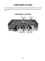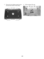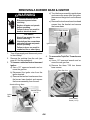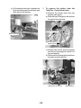
1
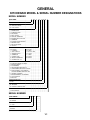
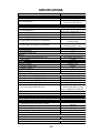
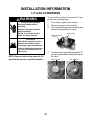
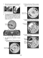
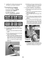
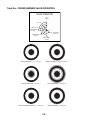
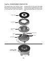
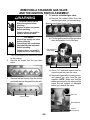
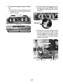
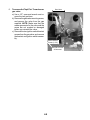
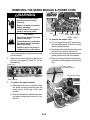
KAC-40 TECHNICAL EDUCATION Pro Line Gas Cooktop With TripleTier Crown Burner Models: KGCV465MSS & KGCV465MMT JOB AID 4317358 FORWARD This KitchenAid Job Aid, “Pro Line Gas Cooktop With TripleTier Crown Burner,” (Part No. 4317358), provides the technician with information on the installation, operation, and service of the Pro Line Gas Cooktop. It is to be used as a training Job Aid and Service Manual. For specific information on the model being serviced, refer to the “Use and Care Guide,” or “Wiring Diagram” provided with the cooktop. The Wiring Diagram used in this Job Aid is typical and should be used for training purposes only. Always use the Wiring Diagram supplied with the product when servicing the unit. GOALS AND OBJECTIVES The goal of this Job Aid is to provide detailed information that will enable the service technician to properly diagnose malfunctions and repair the Pro Line Gas Cooktop. The objectives of this Job Aid are to: • • • • Understand and follow proper safety precautions. Successfully troubleshoot and diagnose malfunctions. Successfully perform necessary repairs. Successfully return the cooktop to its proper operational status. WHIRLPOOL CORPORATION assumes no responsibility for any repairs made on our products by anyone other than Authorized Service Technicians. Copyright © 2004, Whirlpool Corporation, Benton Harbor, MI 49022 - ii - TABLE OF CONTENTS Page GENERAL ............................................................................................................................... 1-1 KitchenAid Model & Serial Number Designations .............................................................. 1-1 Model & Serial Number Label And Wiring Diagram Locations .......................................... 1-2 Specifications ..................................................................................................................... 1-3 KitchenAid Warranty .......................................................................................................... 1-4 INSTALLATION INFORMATION ........................................................................................... 2-1 L.P. Gas Conversion .......................................................................................................... 2-1 THEORY OF OPERATION ..................................................................................................... 3-1 TripleTier Crown Burner ................................................................................................... 3-1 COMPONENT ACCESS ......................................................................................................... 4-1 Component Locations ........................................................................................................ 4-1 Removing The Burners And Cooktop ................................................................................ 4-2 Removing A Burner Base & Ignitor .................................................................................... 4-4 Removing A Standard Gas Valve And The Ignition Switch Assembly............................... 4-6 Removing The TripleTier Crown Burner Ignition Switch And Gas Valve ......................... 4-8 Removing The Spark Module & Power Cord ................................................................... 4-10 COMPONENT TESTING ........................................................................................................ 5-1 Ignition Switches ................................................................................................................ 5-1 WIRING DIAGRAM ................................................................................................................. 6-1 Wiring Diagram .................................................................................................................. 6-1 - iii - — NOTES — - iv - GENERAL KITCHENAID MODEL & SERIAL NUMBER DESIGNATIONS MODEL NUMBER MODEL NUMBER K GC V 46 5 M SS 0 K = KITCHENAID BRAND PRODUCT IDENTIFICATION EC = ELECTRIC COOKTOP GC = GAS COOKTOP MERCHANDISING SCHEME C = CERAMIC GLASS D = DOWNDRAFT VENT E = ELECTRONICS G = GRILL / GRIDDLE M = MODULAR / DOWNDRAFT N = INTERNATIONAL COLLECTION P = COMMERCIAL S = STANDARD PORCELAIN METAL T = TEMPERED GLASS V = VBL PRO LINE SERIES X = 208 VOLTS CAPACITY / SIZE / SERIES / CONFIGURATION 1ST POSITION 2ND POSITION 1 = STANDARD 0 = 30" WIDE 2 = GRILL / GRIDDLE 2 = 42˝ OR 12˝ WIDE 3 = TEMPERED GLASS 3 = 33˝ WIDE 4 = COMMERCIAL 5 = 15˝ WIDE 5 = CERAMIC GLASS 6 = 36˝ WIDE 8 = MODULAR DOWNDRAFT 8 = 48˝ WIDE 0 = 2 BURNER / ELE. SYS. FEATURES 0 = STANDARD ELEMENTS / BURNERS 1 = RADIANT ELEMENTS 2 = DUAL ELEMENTS 3 = SEALED BURNERS WITH GRIDDLE 4 = SEALED BURNERS WITH GRILL & GRIDDLE 5 = SEALED BURNERS / CAST ELEMENTS OR SEALED BURNERS WITH TRIPLE TIER 6 = 5 BURNERS / ELEMENTS 7 = HALOGEN ELEMENTS / OR 6 BURNERS 8 = TOUCH CONTROLS 9 = INDUCTION YEAR OF INTRODUCTION M = 2003 COLOR CODE MT = METEORITE SS = BRUSHED STAINLESS STEEL ENGINEERING CHANGE 0 = BASIC RELEASE SERIAL NUMBER SERIAL NUMBER X P 27 06472 MANUFACTURING SITE X = OXFORD YEAR OF PRODUCTION P = 2003 WEEK OF PRODUCTION 27th Week PRODUCT SEQUENCE NUMBER 1-1 MODEL & SERIAL NUMBER LABEL AND WIRING DIAGRAM LOCATIONS The Model/Serial Number label and Wiring Diagram locations are shown below. Model & Serial Number Label Location (Bottom Of Front Panel) Wiring Diagram Location (Behind Front Panel) 1-2 SPECIFICATIONS Model Number Release Info Model Description KGCV465MMT / SS Sealed Cooktop 36" with Low Simmer to Ultra Power Wok Burner Size-Configuration Dimensions/Specifications Exterior Dimensions Overall Height (in) Overall Width (in) Overall Depth (in) Cutout Height (in) (Measure Or Min/Max) Cutout Width (in) (Measure Or Min/Max) Cutout Depth (in) (Measure Or Min/Max) Weight Net Weight (lbs) Shipping Weight (lbs) Ratings Electric Voltage/Phase/Frequency (Hz) Circuit Amps Exterior Cooktop Controls Cooktop Control Type Cooktop Control # Gas Cooktop Burners Gas Burner Type Gas Burner Configuration Gas R Front Output (BTU)(Nat/LP) Gas L Front Output (BTU)(Nat/LP) Gas R Rear Output (BTU)(Nat/LP) Gas L Rear Output (BTU)(Nat/LP) 7 1/2" (Not Including Grates or Backsplash); Backsplash: 6 1/2" 36" 26 7/8" 7 1/4" 36" (Front Console); 35 1/4" (Cooktop Body) 22 1/4" (Cutout Back to Corner of Notch); Notch: Varies 151 171 120 V/Single Phase/60 Hz 15 Amp Push-to-Turn Infinite 5 Yes Sealed 6000 BTU/5000 BTU 6000 BTU/5000 BTU 15000 BTU/12000 BTU 15000 BTU/12000 BTU Triple Tier Flame: Ultra Simmer 600 BTU/600 BTU to Ultra Power 18000 BTU/14000 BTU Electronic Kit Included Gas Center Output (BTU)(Nat/LP) Gas Ignition LP Conversion Interior Accessories Wok Ring Miscellaneous InstaWok(TM) Ring Included 8285418; LP Conversion, 8285441 4317358 8285400 AGA,CGA 3 1/2 Foot/3 Wire Installation Instructions Part/Comment Service Manual Part/Comment Use & Care Guide Part/Comment Agency Approvals Power Cord Length & # Wires Warranty Full Extended Gas Burners 12 Mo 2nd through 5th year, parts 1-3 KITCHENAID WARRANTY ONE-YEAR FULL WARRANTY For one year from the date of purchase, when this appliance is operated and maintained according to instructions attached to or furnished with the product, KitchenAid will pay for factory specified parts and repair labor costs to correct defects in materials or workmanship. Service must be provided by a KitchenAid designated service company. SECOND THROUGH FIFTH YEAR LIMITED WARRANTY ON ELECTRIC ELEMENTS, CERAMIC GLASS COOKTOP, GAS BURNERS, AND SOLID STATE TOUCH CONTROL SYSTEM On electric ranges and electric cooktops, in the second through fifth years from the date of purchase, when this appliance is operated and maintained according to instructions attached to or furnished with the product, KitchenAid will pay for factory specified parts for any electric element to correct defects in materials or workmanship. On ceramic glass ranges and ceramic glass cooktops, in the second through fifth years from the date of purchase, when this appliance is operated and maintained according to instructions attached to or furnished with the product, KitchenAid will pay for factory specified parts for the ceramic glass cooktop. KitchenAid warrants that the ceramic glass cooktop will not discolor, the cooktop pattern will not wear off, the rubber seal between the ceramic glass cooktop and porcelain edge will not crack, the ceramic glass cooktop will not crack due to thermal shock and the surface unit elements will not burn out. On gas ranges and gas cooktops, in the second through fifth years from the date of purchase, when this appliance is operated and maintained according to instructions attached to or furnished with the product, KitchenAid will pay for factory specified parts for any gas burner to correct defects in materials or workmanship. On ranges and built-in ovens, in the second through fifth years from the date of purchase, when this appliance is operated and maintained according to instructions attached to or furnished with the product, KitchenAid will pay for factory specified parts for the porcelain oven cavity/inner door if the part rusts through due to defects in materials or workmanship. KitchenAid will pay for factory specified parts for solid state touch control system and Magnetron tube in combination ovens to correct defects in materials or workmanship. SIXTH THROUGH TENTH YEAR LIMITED WARRANTY ON RANGES AND BUILT-IN OVENS PORCELAIN OVEN CAVITY/INNER DOOR On ranges and built-in ovens only, in the sixth through tenth years from date of purchase, when this appliance is operated and maintained according to instructions attached to or furnished with the product, KitchenAid will pay for factory specified parts for the oven cavity/inner door if the part rusts through due to defects in materials or workmanship. KitchenAid will not pay for: 1. Service calls to correct the installation of your appliance, to instruct you how to use your appliance, to replace house fuses or correct house wiring, or to replace owner-accessible light bulbs. 2. Repairs when your appliance is used in other than normal, single-family household use. 3. Pickup and delivery. Your appliance is designed to be repaired in the home. 4. Damage resulting from accident, alteration, misuse, abuse, fire, flood, improper installation, acts of God or use of products not approved by KitchenAid or KitchenAid Canada. 5. Repairs to parts or systems resulting from unauthorized modifications made to the appliance. 6. Replacement parts or repair labor costs for units operated outside the United States or Canada. 7. In Canada, travel or transportation expenses for customers who reside in remote areas. 8. Any labor costs during the limited warranty periods. KITCHENAID AND KITCHENAID CANADA SHALL NOT BE LIABLE FOR INCIDENTAL OR CONSEQUENTIAL DAMAGES. Some states or provinces do not allow the exclusion or limitation of incidental or consequential damages, so this exclusion or limitation may not apply to you. This warranty gives you specific legal rights, and you may also have other rights which vary from state to state or province to province. Outside the 50 United States and Canada, this warranty does not apply. Contact your authorized KitchenAid dealer to determine if another warranty applies. If you need service, first see the “Troubleshooting” section of the Use and Care Guide. After checking “Troubleshooting,” additional help can be found by checking the “Assistance or Service” section, or by calling the KitchenAid Customer Interaction Center, 1-800-422-1230 (toll-free), from anywhere in the U.S.A. In Canada, contact your KitchenAid designated service company or call 1-800-807-6777. 1-4 INSTALLATION INFORMATION L.P. GAS CONVERSION To convert the cooktop for use with L.P. gas, perform the following steps. 1. Turn off gas supply to the cooktop. 2. Disconnect power to the cooktop. 3. Use a screwdriver and remove the access cap on the gas distribution valve. WARNING Electrical Shock Hazard Disconnect power before servicing. Replace all parts and panels before operating. Failure to do so can result in death or electrical shock. Access Cap Gas Distribution Valve Fire Hazard Shut off gas supply line valve. Make all conversions before turning gas supply valve back on. Failure to follow these instructions can result in explosion, fire, or other injury. 4. NOTE: Gas conversion from natural to L.P. gas must be done by a qualified installer. Turn the access cap so that the letters L.P. are facing up and then reinstall the cap on the valve. NAT Position 2-1 L.P. Position 5. 6. Remove the grates from the cooktop and the burner caps from the burner bases. b) Remove the three T-20 torx screws from the burner cover and remove the cover. Burner Cover Screw (1 of 3) To convert the left and right front and rear burners, use a 7 mm nut driver, and remove the orifices . NOTE: Place a small piece of masking tape along the inside edge of the nut driver to help keep the orifice in the driver. c) Remove the two T-20 torx screws from the orifice cover and remove the cover. Orifice Cover (2 Screws) Burner Orifice d) Use a 7 mm nut driver and remove the two burner orifices. TripleTier Crown Burner 7. To convert the TripleTier Crown burner: a) Remove the four T-20 torx screws from the burner ring and remove the ring. External Burner Orifice Internal Burner Orifice Burner Ring Screw (1 of 4) 2-2 8. Install the L.P. orifices in the burners (see the charts for the proper locations). d) Quickly turn the gas valve from LO to HI, and then back to LO. The flame should be on steady and not go out. Parts provided with conversion kit: L.P. Orifice Package—8285442 Conversion Instructions—8285441 Conversion Label—8285453 L.P. Orifice Package for TripleTier Crown Burner—8285443 11. To set the TripleTier Crown Burner: a) Remove the control knobs from the five gas valves. b) Remove the control panel from the front panel (see page 4-6). c) Pull the rubber shield off the gas valve stem. d) Turn on the power and gas and set the inner and outer burner flames to the LO setting. e) One at a time, insert a flat-blade screwdriver into the slot in the external and internal adjustment screws. Turn each of the screws until the flame sizes are as small as possible without going out. Standard Burners (4) Rating 5,000 B.T.U. 12,000 B.T.U. Color Red Blue Size 0.70 mm 1.10 mm Burner Small Large TripleTier Crown Burner Rating 11,800 B.T.U. 2,200 B.T.U. Color Brown Orange Size 1.00 mm 0.42 mm Burner External Internal TripleTier Burner Internal Flame LO Adjustment 9. Replace the burner caps and grates. 10. To set the low flame size for the standard burners: a) Remove the control knob from the gas valve. b) Turn on the power and gas and set the flame to the LO setting. c) Insert a flat-blade screwdriver into the hollow stem of the gas valve and engage it with the slot in the adjustment screw. Turn the screw until the flame size is as small as possible without going out. TripleTier Burner External Flame LO Adjustment f) Quickly turn the gas valve from LO to HI, and then back to LO. Both flames should be on steady and not go out. Standard Burner Flame LO Adjustment 2-3 — NOTES — 2-4 THEORY OF OPERATION TripleTier CROWN BURNER The burner valve for the new 18,000 BTU TripleTier Crown burner has two gas outlets, and two burner orifices. The center burner operates as a 600 BTU simmer burner, and an 18,000 BTU full burner. The simmer burner operates when the valve burner stem is turned to that position of its rotation (see the following page). A valve-mounted ignition switch provides burner ignition from the single 6-slot spark module, which is mounted on the left side behind the front panel. TripleTier Valve W/Ignition Switch Burner Valve On Gas Manifold Burner Valve Ignition Switch 3-1 TripleTier CROWN BURNER VALVE OPERATION VALVE OPERATION OFF POSITION 1° LIGHT 42° STOP LIGHT 75° INNER BURNER 90° FULL RATE INNER BURNER 130° LOW RATE 230° TRIPLE FLAMES LOW RATE 180° TRIPLE FLAMES FULL RATE Inner Crown Ignition — 42 to 75 Degrees Outer Crown Ignition — Angle >130 Degrees Inner Crown Maximum — 90 Degrees All Crowns Maximum — 180 Degrees Inner Crown Minimum (Detention) — 130 Degrees All Crowns Minimum — 230 Degrees 3-2 TripleTier CROWN BURNER CONSTRUCTION The exploded view of the TripleTier Crown burner shows how the burner is disassembled. The burner uses two orifices that are located in the burner base. One of the orifices is mounted in the top of the burner base, while the other orifice is concealed by a cover. Technicians should be aware of the second orifice when performing any service, or gas conversion. Burner Caps Burner Ring Burner Base Cover Orifice Cover Ignitor 2 Orifices Burner Base TripleTier Crown Burner Assembly 3-3 — NOTES — 3-4 COMPONENT ACCESS This section instructs you on how to service each component inside the KitchenAid Pro Line Gas Cooktop With TripleTier Crown Burner. The cooktop components and their locations are shown below. COMPONENT LOCATIONS TripleTier Crown Burner W/Ignitor Spark Module TripleTier Crown Burner Gas Valve & Ignition Switch 4-1 Standard Burner W/Ignitor (4) Standard Burner Gas Valve (4) & Ignition Switch (4) REMOVING THE BURNERS AND COOKTOP Left & Right Front & Rear Burners WARNING Electrical Shock Hazard Disconnect power before servicing. Replace all parts and panels before operating. Failure to do so can result in death or electrical shock. 2 Burner Screws Fire Hazard Shut off gas supply line valve before servicing. Check all gas line connections and replace all parts and panels before operating. Failure to do so can result in explosion, fire or other injury. 1. 2. 3. TripleTier Crown Burner 4. Turn off gas supply and disconnect power to the cooktop. Remove the grates from the cooktop and the burner caps from the burners. To remove the TripleTier Crown burner: a) Remove the four T-20 torx screws from the burner ring and remove the ring. Burner Ring Screw (1 of 4) To remove a standard burner, remove the two T-20 torx screws from the left and right front and rear burners, and remove the burners from the cooktop (see the photo at the top of the right column). b) Remove the three T-20 torx screws from the burner cover and remove the cover. Burner Cover Screw (1 of 3) 4-2 5. Remove the four phillips screws from the front and rear corners of the cooktop 6. Rear Screws Front Screws 4-3 Lift the cooktop off the unit. REMOVING A BURNER BASE & IGNITOR d) Turn the burner assembly upside down and remove the screw from the ignitor, then remove the ignitor from the burner base. e) Remove the two burner base hex-head screws from the bracket and remove the burner base. WARNING Electrical Shock Hazard Disconnect power before servicing. Replace all parts and panels before operating. Failure to do so can result in death or electrical shock. Burner Base Screws Fire Hazard Shut off gas supply line valve before servicing. Check all gas line connections and replace all parts and panels before operating. Failure to do so can result in explosion, fire or other injury. 1. 2. 3. Ignitor Screw Turn off gas supply and disconnect power to the cooktop. Remove the cooktop from the unit (see page 4-2 for the procedure). To remove a standard burner base and ignitor: a) Use a 1/2″ open-end wrench and remove the gas line. b) Disconnect the ignitor wire from the ignitor terminal. c) Remove the two hex-head screws from the burner base bracket and remove the burner assembly from the unit. 4. To remove the TripleTier Crown burner base: a) Use a 1/2″ open-end wrench and remove the rear gas line. b) Remove the three T-20 torx burner base screws. Rear Gas Line Standard Burner Base Bracket Screw (1 of 2) Ignitor Wire Burner Base Screw (1 of 3) Gas Line 4-4 c) Lift the burner base from its bracket as far as the bottom gas line will allow, and then remove the gas line. 5. To remove the ignitor from the TripleTier Crown burner base: a) Remove the burner base from the bracket (see step 4). b) Slide the clip off the ignitor and remove the ignitor from the base. Slide Clip Off Ignitor Bottom Gas Line Ignitor Wire From Spark Module c) Remove the control and front panels from the unit (see pages 4-6 and 4-7 for the procedures). d) Disconnect the orange ignitor wire from the spark module terminal. Orange Wire Connector 4-5 Spark Module REMOVING A STANDARD GAS VALVE AND THE IGNITION SWITCH ASSEMBLY 4. WARNING Electrical Shock Hazard Disconnect power before servicing. Replace all parts and panels before operating. Failure to do so can result in death or electrical shock. Standard Valve Rubber Shield (1 of 4) Fire Hazard Shut off gas supply line valve before servicing. Check all gas line connections and replace all parts and panels before operating. Failure to do so can result in explosion, fire or other injury. 1. 2. To remove a standard gas valve: a) Remove the rubber shield from the standard gas valve you are servicing. b) Pull the ignition switch off the gas valve stem and position it out of the way. Pull Switch Off Valve Stem Turn off gas supply and disconnect power to the cooktop. Remove the knobs from the gas valve stems. Standard Ignition Switches 3. c) Use a 1/2″ open-end wrench and remove the gas line from the valve. d) Remove the gas valve mounting screw, and remove the valve from the gas manifold. NOTE: Make sure that the rubber grommets for the valve and the screw are not cracked or damaged before you reinstall the valve. Remove the two screws from the control panel and remove the panel from the unit. Screw Control Panel Gas Line Screw Gas Manifold Screw w/Grommet 4-6 5. To remove the ignition switch assembly: a) Remove the two front and three bottom screws from the front panel and remove the panel. b) Pull the 4 ignition switches off the standard gas valve stems. NOTE: The ignition switches must be replaced as an assembly. Front Screws Pull Switch Off Valve Stem Front Panel c) Disconnect the black ignition switch wire from the harness connector, and the white wire from the spark module terminal. NOTE: If necessary, loosen or cut the wire tie from around the black ignition switch wire. Bottom Screws Black Wire Connector White Wire Connector 4-7 Spark Module REMOVING THE TripleTier CROWN BURNER IGNITION SWITCH AND GAS VALVE 4. WARNING Electrical Shock Hazard Disconnect power before servicing. Replace all parts and panels before operating. Failure to do so can result in death or electrical shock. Rubber Shield 5. Fire Hazard Shut off gas supply line valve before servicing. Check all gas line connections and replace all parts and panels before operating. Failure to do so can result in explosion, fire or other injury. 1. 2. 3. Remove the rubber shield from the TripleTier Crown burner gas valve. To remove the TripleTier Crown burner ignition switch: a) Disconnect the wire connectors from the ignition switch terminals. b) Remove the two screws from the ignition switch and remove the switch from the bracket. Turn off gas supply and disconnect power to the cooktop. Remove the knobs from the gas valve stems. Remove the two screws from the control panel and remove the panel from the unit. Ignition Switch & 2 Screws Screw Control Panel Screw 4-8 Switch Wires 6. To remove the TripleTier Crown burner gas valve: a) Use a 1/2″ open-end wrench and remove the two gas lines. b) Remove the gas valve mounting screw, and remove the valve from the gas manifold. NOTE: Make sure that the rubber grommets for the valve and the screw are not cracked or damaged before you reinstall the valve. c) Remove the two ignition switch bracket screws from the gas valve, and remove the bracket and ignition switch assembly. Gas Lines Switch Bracket Screw (1 of 2) Gas Valve Screw & Grommet 4-9 REMOVING THE SPARK MODULE & POWER CORD WARNING Screw (1 of 2) Spark Module Electrical Shock Hazard Disconnect power before servicing. Replace all parts and panels before operating. Failure to do so can result in death or electrical shock. Black White Fire Hazard Shut off gas supply line valve before servicing. Check all gas line connections and replace all parts and panels before operating. Failure to do so can result in explosion, fire or other injury. 1. 2. 4. Turn off gas supply and disconnect power to the cooktop. Remove the control and front panels from the unit (see pages 4-6 and 4-7 for the procedures). Power Cord Orange Dark Light Light Brown Brown Brown Green Yellow To remove the power cord: a) Cut or loosen the wire tie, and disconnect the black power cord wire from the spark module terminal. b) Disconnect the other black power cord wire from the harness connector. c) Remove the screw and disconnect the green ground wire from the chassis. d) Remove the strain relief from the chassis and remove the power cord from the unit. Remove Power Cord Strain Relief Ground Wire Screw Spark Module 3. To remove the spark module: a) Disconnect the wire connectors from the spark module terminals (see the wiring photo at the top of the right column). b) Remove the two hex-head screws from the spark module and remove it from the unit. Black Wire Connector Wire Tie Black Wire 4-10 COMPONENT TESTING Before testing any of the components, perform the following checks: • The most common cause for control failure is corrosion on connectors. Therefore, disconnecting and reconnecting wires will be necessary throughout test procedures. • All tests/checks should be made with a VOM or DVM having a sensitivity of 20,000 ohmsper-volt DC, or greater. • Check all connections before replacing components, looking for broken or loose wires, failed terminals, or wires not pressed into connectors far enough. • Resistance checks must be made with power cord unplugged from outlet, and with wiring harness or connectors disconnected. WARNING Electrical Shock Hazard Disconnect power before servicing. Replace all parts and panels before operating. Failure to do so can result in death or electrical shock. IGNITION SWITCHES 3. Refer to pages 4-6 and 4-8 for the procedure for servicing the ignition switches. NOTE: The four standard ignition switches will be serviced as a complete assembly. If a switch is defective, the complete assembly must be replaced. The TripleTier Crown burner ignition switch is serviced separately. 1. Turn off gas supply and disconnect power to the cooktop. 2. Set the ohmmeter to the R x 1 scale. Locate the black and white ignition switch connectors, (one is connected to the spark module, and the other is connected to the main wire harness), and disconnect them. Black Wire Connector White Wire Connector 4. 5. TripleTier Crown Burner Ignition Switch Standard Burner Ignition Switch 6. 5-1 Turn all of the switches to the Off position. Touch the ohmmeter test leads to the connectors on the black and white switch wires. The meter should indicate an open circuit (infinite ∞). Separately turn each of the five controls to the “lite” position. The meter should indicate a closed circuit (0 ohms) for each switch. — NOTES — 5-2 WIRING DIAGRAM POWER CORD PLUG Neutral 5/16" Blade Line 1/4" Blade 120 VAC, 60 Hz 1 Phase 15 or 20 Ampere Ground Round Pin GRN or GRN/YEL BLK Ground WHT Connect .250 Terminals WHT SPARK MODULE BLK IGNITION SWITCHES (ON VALVES) Electric circuit closed when knob is rotated 55 to 95 degrees counterclockwise from OFF YEL or BRN (6) IGNITOR ELECTRODES 6-1 — NOTES — 6-2 PRODUCT SPECIFICATIONS AND WARRANTY INFORMATION SOURCES IN THE UNITED STATES: FOR PRODUCT SPECIFICATIONS AND WARRANTY INFORMATION CALL: FOR WHIRLPOOL PRODUCTS: 1-800-253-1301 FOR KITCHENAID PRODUCTS: 1-800-422-1230 FOR ROPER PRODUCTS: 1-800-447-6737 FOR TECHNICAL ASSISTANCE WHILE AT THE CUSTOMER’S HOME CALL: THE TECHNICAL ASSISTANCE LINE: 1-800-253-2870 HAVE YOUR STORE NUMBER READY TO IDENTIFY YOU AS AN AUTHORIZED SERVICER FOR LITERATURE ORDERS: PHONE: 1-800-851-4605 FOR TECHNICAL INFORMATION AND SERVICE POINTERS: www.servicematters.com IN CANADA: FOR PRODUCT SPECIFICATIONS AND WARRANTY INFORMATION CALL: 1-800-461-5681 FOR TECHNICAL ASSISTANCE WHILE AT THE CUSTOMER’S HOME CALL: THE TECHNICAL ASSISTANCE LINE: 1-800-488-4791 HAVE YOUR STORE NUMBER READY TO IDENTIFY YOU AS AN AUTHORIZED SERVICER