1
Donated by John & Susan Hansen - For Personal Use Only
L-UNE MOTOR TRUCK SERVICE MANUAL
WHEELS &
RIMS
Index
Page 1
WHEELS AND RIMS qROUP
SECTION "A"
Page
1
General . • . . . . . . . . • • . . . . •
Front wheel bearing adjustment
1
Rear wheel bearing adjustment.
I, 2
Oil seals - front wheels.
3
Oil seals - rear wheels.
3
3, 4
Oil seals - rear wheels (Timken axles)
Wheels and rims . . . . . • . • . . . . . .
3
Wheel bolt nut tensions (disc wheels) .
3, 4
TIRES
SECTION "B"
Page
Tire inflation. . . . . .
1
Inflation . . .
I
Overloading.
2
Speeds . . . .
2
Service load and inflation table.
4
••
Wheel, rim, and hub bolt tension application chart . .
PRINTED IN UNITEO STATES OF' AM£A1CA
3
4,5, 6, 7
Donated by John & Susan Hansen - For Personal Use Only
Donated by John & Susan Hansen - For Personal Use Only
L-UNE MOTOR TRUCK SERVICE MANUAL
WHEELS &:
RIMS
Section A
Page 1
WHEELS General
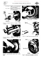
Tapered roller bearings carry the wheels
and are adjustable. Satisfactory operation and
life depends upon correct adjustment and prop
er lubrication. Every 3,000 to 5,000 miles re
move the wheels, clean and inspect the bearings,
races and wheel hubs. Then repack the bear
ings, replace the wheels and adjust the bearings.
Use a short fibre wheel bearing grease.
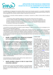
NOTE: R-I060 series axle (Semi-floating)
rear wheel bearings are adjusted by shims lo
cated between backing plate and end of axle
housing. (See Fig. 1.)
Remove plug and ins tall lubricator fitting
as shown in Fig. 1 to lubricate bearing, re
ins tall plug.
Illustrations used in this section may vary
due to the availability of Stamped, Cast and Budd
wheels on various models, but the arrangement
of bearings, grease seals and retainers are
similar. Therefore, use illustrations for wheel
mounting on the axle ONLY and disregard the
design of wheel and brake.
Front Wheel Bearing Adjustment
Use an 8 11 wrench and apply steady pres
sure with one hand, pulling up the adjusting nut
until a definite drag is felt on the wheel. Rotate
wheel at the same time nut is being tightened
to be sure that all parts are correctly seated.
Back-off nut tofirst castellation and install new
cotter pin.
Front wheel bearings should never be given
a loose adjustment for such will not permit the
rollers and races to be in proper contact and
bearing failure will result.
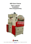
Fi g. 2
Fig. 2 illustrates construction details of
rear wheel assembly on axles R-I060 series.
Rear Wheel Bearing Adjustment
Rotate wheel and tighten inner adjusting
nut until a drag or bind is felt, then back off
nut about 1/6 11 turn. Install lockwasher and
outer nut, and after tightening securely, check
the adjustment. There should be a very slight
shake in the wheel (with axle shaft removed) if
the adjustment is correct.
Grease
guard
Backing plate reinforcement Fig.
PRINTE.D IN UNITED STATES OF' AMERICA
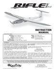
Fig. 3
A·22935
Fig. 3 illustrates construction details at
rear wheel assembly on axles R-I070 series.
Donated by John & Susan Hansen - For Personal Use Only
WHEELS &
RIMS
Section A
Page 2 L-UNE MOTOR TRUCK SERVICE MANUAL
Fig. II-
Fig. 4 illustrates construction details at
rear wheel assembly on axles R-1165 and
R-1170 series.
Fig. 6 Fig. 6 illustrates construction details at
rear wheel assembly on axles of R-l 741 series.
Fig. 5 Fig. 5 illustrates construction details at rear wheel assembly onaxles of R-l440, R-1470, R-l530, R-2470, R-2475, R-2490, R-1555, R-l630, R-2580, R-2600, R-l540, R-l640, RF-1455, RF-l575, RF-1670, R-2465, R-2466 and R-2585 series. A-.2.2830
Fig. 7 Fig. 7 illustrates construction details at
rear wheel assembly on axles of R-173l, R-18l 0,
R-2741 and R-2800 series.
Donated by John & Susan Hansen - For Personal Use Only
L-LINE MOTOR TRUCK SERVICE MANUAL
Oil Seals - Front Wheels
The front wheel oil seal should be inspected
when hub or wheel is removed and replaced if
necessary. When installing new seal, dip in
light oil first and make sure it is properly in
stalled in the hub to assure satisfactory serv
ice. The machined surface of the steering
knuckle must be clean and free of nicks and
burrs so that sealing element can seat properly
on the surface provided.
Oil Seals - Rear Wheels
Place inner seal assembly in hub and drive
carefully into place being sure that the seal
bottoms and is aligned square with the hub. The
outer seal is assembled into the bearing lock
nut and is self adjusted on the axle shaft when
the axle shaft is tightened against the hub.
Machined surfaces of the axle housing and shaft
must be clean and free of nicks and burrs to
assure satisfactory service of the seals.
Oil Seals - Rear Wheels (Timken Axles)
The inner and outer wheel hub oil seals
mustbe properly installed to assure satisfactory
service. Machined surfaces of component parts
and sealing surfaces of wiper rings must be
clean and free of nicks or burrs. The sealing
elements must seat evenly on the wiper rings.
Special tools (SE-1581) have been provided
for proper installation of oil seals and wiper
rings. The following illustrations show these
tools in use for their specific application.
Lubricate inner seat with wheel bearing
grease and place on end of axle housing. Using
inner seal adapter and driving sleeve, drive the
seal carefully onto the end of the axle housing
until it is seated firmly against shoulder on the
housing (Fig. 8).
Using a square as shown in Fig. 9, check
from the end of the axle housing to the face of
the sealing element at 90 0 intervals. The seal
ing element should not be in excess of .010" off
parallel with the end of the housing.
Install inner seal wiper ring in wheel hub
as shown in Fig. 10. The ring has one face
ground and one face, polished. Position the
polished face outward to contact the sealing
element, and the ground face seated firmly
against inner bearing cup.
Following installation of the wiper ring,
check installation using a .002" feeler gauge
(Fig. 11) between the ring and bearing race. If
the ring is in excess of .002" off parallel with
the bearing cup, remove ring, check for dirt or
other obstruction and reinstall.
PRINTED 1N UNITED STATES
or
AMERICA
WHEELS &:
RIMS
Section A
Page 3
Install inner wheel bearing. (Bearing must
be properly lubricated before installation.) In
stall wheel hub assembly and outer wheel bear
ing. Turn inner nut until it is tight against the
outer bearing cone and at the same time revolve
the wheel to seat the tapered bearings and oil
seal. Continue to tighten the nut, while revolv
ing the wheel until a definite drag is felt, and
then back off about one-sixth of a turn. Place
the locking washer on the axle with the lug in
the groove. Place the washer against the nut
so that the pin in the nut enters one of the holes
in the washer, using either side of the locking
washer to accomplish this. If it is necessary
to turn the inner nut to bring the pin into line
with one of the holes, install washer so that the
least movement of the nut is ne~essary. Install
outer nut and tighten securely.
Install the outer oil seal wiper ring and
gasket (Fig. 12).
Place gasket inside cup of wiper ring and
over end of axle housing end. Use adapter driv
er and drive the outer wiper ring carefully onto
the end of the axle housing until it seats fi rmly
against the gasket.
Place gasket against wheel hub as shown in
Fig. 13.
Install oute r seal assembly and place outer
gasket over hub studs. Install axle shaft, ta
pered dowels, lockwashers and stud nuts, and
tighten securely.
Wheels and Rims
Wheel stud nuts should be inspected and
tightened at regular intervals. Rim clamp nuts
should be kept tight and the rim and tire align
ment in relation to the wheel should be checked
to make sure tire is running true.
Where left- and right-hand thread studs and
nuts are used, the left-hand thread nuts can be
identified by a small groove machined around
the flats and the studs, by letter "L" stamped
on the head: Use left-hand nuts (stamped tlV!)
on the left side of truck.
Wheel Bolt Nut Tensions (Disc Wheels)
KELSEY -HAYES WHEELS -- When tighten
ing wheel bolt nuts on Kelsey-Haye s di sc wheels,
do not use excessive leverage. Use a wrench of
the same length as that furnished with the tool
kit.
BUDD WHEELS -- When tightening wheel
boltnuts on Budd disc wheels, use wrench which
will provide sufficient leverage to tighten as
follows: (see next page)
WHEELS &
RIMS
Section A
Page 4
Donated by John & Susan Hansen - For Personal Use Only
L-L1NE MOTOR TRUCK SERVICE MANUAL
9/16 11 Bolt -- tighten to 250 foot-pounds.
(100 pounds pressure on a
.
2-112 foot wrench.)
3/411 Bolt -- tighten to 350 foot-pounds.
(140 pounds pressure on a
2-1/2 foot wrench.)
Fig. I I - Checking wiper ring a1 ignment.
Fig. 8 - Installing
housing.
inner oil
seal
Outer seal
wiper ring
on axle
Fig. 12 - Install ing outer wiper seal ring.
Fig. 9 - Checking
assembly.
alignment of
inner seal
Cakeb
Outer
---seal assembly
~~.
Fig. 10 - Installing inner wiper ring in wheel
hub.
--~
Fig. 13 - Outer seal and gaskets installed.
Donated by John & Susan Hansen - For Personal Use Only
WHEELS &
RIMS
L-UNE MOTOR TRUCK SERVICE MANUAL
Section B
Page 1
TIRES
Tire Inflation
Inflation
Proper tire inflation, tire loads, and road
speeds are important determining factors gov
erning tire mileage, and als 0 aifec t steering
ease and maneuverability. Inflation pressures
should be checked at regular and freq uent inter
vals and the pressures maintained to specifica
tions. Use an accurate tire pressure gauge.
Inflation pre s sures should be checked when
tires are cool. Never bleed a hot tire.
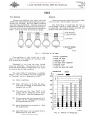
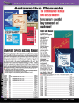
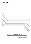
The chart (Fig. 7) illustrates the loss in
tire mileage caused by under inflation. It will
be noted that a tire under-inflated only 20'10 will
produce only 70"10 normal mileage.
% OVER INFLATION
) % UNDER INFLATION
----'
J % INFLATION
t#-==~---
92%
100%
70%
% EXPECTED NORMAL
25%
50%
SERVICE
A·I6013
Fig. I - Inflation vs. Mi leage.
A-INITIAL CONDITIONS B-AFTER 140 MILES Over-inflation is also costly for a tire
which is 20'10 over-inflated will produce only
92% normal tire mileage.
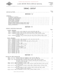
C-PRESSURE "BLED" D-140 MILES AFTER "BLEEDING" "Bleeding" of air from hot tires should
never be practiced. The pressure will be re
duced but an increase in temperature will result
as soon as the driving continues.
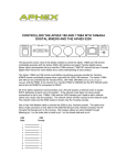
E-PRESSURE "BLED" F-AFTER 200 MILES-TIRE FAILED TEMPERATURE The chart (Fig. 2) illustrates a condition
where a tire was started cool with a pressure
of 70 pounds, and at a temperature of 80 0 :
(A) Initial conditions.
(B) After 140 miles of driving the pres
sure had increased to 85 pounds and
temperature to 200 0 •
(
280
0
240
0
200
160
t
PRESSURE
-
~
r:;
r:;
r;: r:;
- -
0
(D) The pressure had now increased to 73
pounds but the tern.perature increase
was approxirn.ately 220 0 •
(E) Again IIbleeding"was resorted to.
the tern.perature.
Note
120
0
-
90
85 80° - 80 %r-
-75
40' - 70
-
0° - 60
tern.pe rature of ove r 250 0
•
PRINTED IN UNITEO STATES OF AMERICA
v::
~
~
1%
%
~r- ~I:/:
v::
% r;: r%f-
%
~
~ '---
V,:/':
tV':
I----
-
D
f
f
r
-,
-
C
~ r
V
~ r--' -
B
V
~I-
%
/;
~
r::
r-
v::r
~
~
r%
-~
-
- 65
~
%
V ':_ ~
%
%
A
(F') After 200 rn.iles the tire failed from a
,.,
~
0
(c) The pressure was then "bled" to 70
pounds and an additional drive made
of 140 rn.iles. Note the tern.perature.
-
fZ?Z?ZLl
....
-
F
E
A·16011
Fig. 2 - Effects of "Bleeding".
Donated by John & Susan Hansen - For Personal Use Only
WHEELS &
RIMS
L-UNE MOTOR TRUCK SERV1CE MANUAL
Section B
Page 2
-~ "Oml",
\ "N,m.II,,'
#~~--
156'7.
100%
70%
50%
39'70
31'70
25%
% Expected normal service
A-J60J2
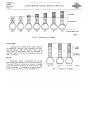
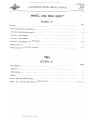
Fig. 3 - Overload vs. Mileage.
Overloading
Loading tires beyond their rated capacity
is expensive, because tire mileages are rap
idly decreased with overloads.
The above
chart {Fig. 3) illustrates how an overload of
only 200/0 will result in tire mileage being only
700/0 of normal.
( % WASTED
)
( % NORMAL
\ TIRE MILEAGE
1FT=9"\\,
Speeds
Excessive speed is definitely one of the
most important factors in loss of tire mileage.
The chart (Fig. 4) illustrates how an increase
in speed from40 to 50 m.p.h. results in an 1810
loss in mileage. An increase of speed from 40 to 60 m.p.h. results in a 3310 mileage loss.
RUBBER
.40 M. P. H.
50 M. P. H.
Fig.
ij -
60 M. P. H.
Speed vs. Mi leage. A·I610B
Donated by John & Susan Hansen - For Personal Use Only
WHEELS &
RIMS
Section B
Page 3
L-UNE MOTOR TRUCK SERVICE MANUAL
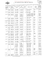
SERVICE LOAD AND INFLATION TABLE
TIRE
SIZE
6.00x16
6.00x20
6.00x20
6.50x16
6.50x17
6.50x20
6.50x20
LOADS AT VARIOUS INFLATION PRESSURES
PLY RATING 32
6
"6
8
6
6
6
8
7.00x16
7.00x17
7.00x17
7.00x18
7.00x20
7.00x20
7.00x24
7.50x16
7.50x16
7.50x17
7.50x18
7.50x20
7.50x20
7.50x24
6
6
8
8
8
10
10
6
8
8
8
8
10
10
8.25x17
8.25x18
8.25x20
8.25x20
10
10
10
12
9.00x18
9.00x18
9.00x20
9.00x20
9.00x22
9.00x24
9.00x24
10
12
10
12
10
10
12
10.00x18
10.00x20
10,00x20
10.00x22
10.00x24
12
12
14
12
12
11.00x20
11.00x20
11.00x22
11.00x24
11.00x24
12
14
12
12
14
12.00x20
12.00x22
12.00x24
14
14
14
13.00x20
13.00x24
16
16
l4.00x20
14.00x24
18
18
36
990
1040
1065
1135
1215
40
I
i
'1
50
1130 1225 1325
1290 1300 1400
1500 1600
60
65
70
1400 1400 1475
1550
1625
1700 1500 1700 1700 1775
1850
1950 1485 1475 1575 1475 1575 1675
1525 1650 1750
1650 1775 1900
1395
1455
45
1560 1560 1650
1650
1750
1875
1950
2000
• 2175
1760
1775
1875
2000
55
1775 1850 2000 2000 2075
2300 2375
75
2250 2575 2150
2475
1850 1900 2000
2000 2100
2125 2250
,2250
2550 .
2100 2200 2375 2375 2500
2700 2850
2080
2150
2325
2200
2300
2475
2330
2425
2600
2470
2550
2750
2750
2585 2675 2900 2900 3025 • 3150 2600
2775
2925
3075
2775
2950
3125
3300
2950
3175
3150
3375
3325
3575
3500
3750
3225
3225
3450
3450
3675
3925
3925
--._
80
2600 . 2700 2975 , 3100 ,~-
..
i
3100
3275
i
3500
' 3725
3275
3475
3700 .3900
3950 i 4150
3900
3900
4100
4125 4350
4350 ,4575
3475
3600
3600
3725
3850
4100
i 4250
4375
3775
4000
4000
4100 I
.4275
-
4250 ,
• 4550
-
4175
4300
4300
4550
4800
4100
i
4625
4900
5200
I
i
3600
3825
3450
3650
3700
3350
I
I
Underscoring denotes maximum recommended loads.
Duals will carry twice the load of corresponding singles.
PRINTED IN UNITED STATES OF AMERICA
I
4850
5200 . 5400
5275
5600
5925
5775 . 6025
6750
6275
7025
7075
7900
7350
8225
I 6475
i
4675
5075
5375
5700
4850
5150
5450
i
4500
4500
4750
5000
5000
4350
i
7650
8525
Donated by John & Susan Hansen - For Personal Use Only
WHEELS &
RIMS
Section B
Page 4
L-UNE MOTOR TRUCK SERVICE MANUAL
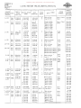
WHEEL, RIM, AND HUB BOLT TENSION APPLICATION CHART
BOLT &:
TRUCK
NUT
BOLT &: STUD
STUD MODEL PART
PART NO.
SIZE
PART NO. SERIES:
TYPE BOLT
I
WHERE USED
TYPE
WHEEL
APPLI
CATION
TENSION
FT.-LBS.
80-90
80-90
L-IIO Bolt
Bolt
69956-H
69955-H
1/2-20NF
1/2-20NF
69958-H
69957-H
Hub to Wheel
Hub to Wheel
F&:R
Kelsey-Hayes
L-120 Stud
Stud
96914-H
96915-H
9/16-18NF
9/16-18NF
96916-H
96917-H
Hub to Wheel
Hub to Wheel
Rear
Budd
175-200
175-200
LM-120
Stud
Stud
96914-H
96915-H
9/16-18NF
9/16-18NF
96916-H
96917-H
Hub to Wheel
Hub to Wheel
Front
Budd
175-200
175-200
L-120
Stud
Stud
81362-H
,8l363-H
9/ 16 - 18 N
9/16-l8N
81364-H
81365-H
Hub to Wheel
Hub to Wheel
Rear Budd
Dual
175-200
175-200
L-120
Stud
Stud
96914-H
969lS-H
9/ l 6-18NF
9/l6-l8NF
969l6-H
96917-H
Hub to Wheel
Hub to Wheel
Rear
Budd
175-200
175-200
L-120 Stud
Stud
81368-H
81369-H
9/16-18N
9/16-18N
81364-H
81365-H
Hub to Wheel
Hub to Wheel
Rear
Budd - Dual
175-200
17S-200
L-150 Bolt
Bolt
119343-H
75887-H
L 150
Bolt
Bolt
Bolt L-lSO
5/8-18NF
5/8-11NC
12261-H
21814-H
4
4
Wheel to Drum
Lug to Rim
Rear
Cast
lS0-180
150-160
70647 -Rl
78193-Rl
78194-Rl
1/2-20NF
3/4-16N
3/4-16N
12260-Rl
84712-H
84711-H
4
Wheel to Drum
Hub to Wheel
Hub to Wheel
Front
Budd
80-90
300-350
300-350
Bolt
Bolt
Bolt 70647-Rl
78193-R1
78l94-Rl
1/2-20NF
3/4-16N
3/4-16N
12260-Rl
847l1-Rl
847l2-Rl
4
Wheel to Drum
Hub to Wheel
Hub to Wheel
Rear
Budd
80-90
300-350
300-350
L-150
Bolt
Bolt
78193-Rl
78l94-Rl 3f4-l6N
3/4-l6N
3/4-16N
3/4-l6N
83lS5-Rl 83l56-Rl 41419- V 4l420-V
Wheel
Wheel
Wheel
Wheel
Rear
Budd
Dual
300-350
300-350
300-3S0
300-350
L-150
Bolt
Bolt
82115 -Rl
6l883-Rl
1/2-20NF
1/2-l3NC l2260-R1
22230- V
4
2
Wheel to Drum
Wheel to Rim
Front
Cast
80-90
70-80
L-150
Bolt
Bolt
5/8-l8NF
5/8-1lNC
1226l-Rl
21S14-H
4
4
Whe el to Drum
Lug to Rim
Rear
Cast
150-180
150-160
L-160
Bolt
Bolt
S2115-RI
61S83-RI
1/2-20NF
1/2-l3NC 12260-R1
22230-V
4
2
Wheel to Drum
Lug to Rim
Front
Cast
80-90
70-80
L-160
Bolt
Bolt
119343-H
61S83-Rl
5/8-18NF
1/2-l3NC
l2261-Rl
22230-V
4
2
Wheel to Drum
Lug to Rim
Rear
Cast - Single
150-180
70-80
L-160 Bolt
Bolt
119343-H
75887 -H 5/8-18NF
5/8-llNC
l226l-Rl
21S14-H
4
4
Wheel to Drum
Lug to Rim
Rear
Cast - Single
150-lS0
150 160
L-160
Stud
Stud
80339-Rl
80340-Rl
3/4-16N
3/4-l6N
8471l-H
84712-H
Hub to Wheel Hub to Wheel
Front
Budd
300-350
300-350
L 160
Stud
Stud
69327-R2
6932S-R2
41419- V
41420-V
83155-H
83156-H Hub
Hub
Hub
Hub
Rear
Budd
Dual
300-3S0
300-350
250-300
250-300
I
119343-H
75887 -H
I
3/4-16N 3/4-16N II-I/8-16N
1 1/8-16N
to
to
to
to
to
to
to
to
Hub
Hub
Hub
Hub
Wheels
Wheels
Wheels Wheels
WHEELS &
RIMS
Section B
Page 5
Donated by John & Susan Hansen - For Personal Use Only
L-L1NE MOTOR TRUCK SERVICE MANUAL
I
NUT
BOL; III
BOLT III STUD
TRUCK
PART NO.
STUD:
SIZE
MODEL PART
PART NO. I
SERIES,
l19343-H
75SS7-H
L-l60
Bolt
Bolt
LF-170
Bolt
Bolt
7S167-R1
77602-Rl
LF-170
Stud
Stud
S0339-Rl
S0340-Rl
LF-170
Bolt
Bolt
L-170 &
L-lSO
Bolt
Bolt
L-lSO
TYPE
BOLT
WHERE USED
TYPE
WHEEL
APPLI
CATION
I TENSION
. FT.-LBS.
5/S-1SNF
5/S-1lNC
12261-R1
2lS14-H
4
4
Wheel to Drum
Lug to Rim
Rear - Dual
Cast
l50-1S0
150-160
5/S-1SNF
5/S-llNC
l2261-Rl
2lS14-H
4
4
Hub to Drum
Lug to Wheel
Rear
Dual
150-1S0
150-160
Hub & Drum to Whee Rear
Hub & Drum to Wheel Budd
Hub & Drum to Wheel Dual
Hub & Dr'llm to Wheel
300-350
300-350
250-300
250-300
3/4--l6N
3/4-l6N
1-1/S-16N
l-lIS-16N
414l9-V
41420-V
S3l55-H
S3155-H
5/S-lSNF
5/S-11NC
12261-Rl
21S14-H
4
4
Wheel to Drum
Lug to Rim
Rear
Cast
l50-1S0
150-160
S2115-Rl
61SS3-Rl
1/2-20NF
1/2-13NC
12260-Rl
22230- V
4
2
Wheel to Drum
Lug to Rim
Front
Cast
SO-90
70-S0
Bolt
Bolt
7S167-Rl
77602-Rl
5/S-1SNF
5/S-llNC
12261-Rl
2lS14-H
4
4
Hub to Drum
Lug to Rim
Rear
Dual
150-1S0
150-160
L-170&
L-lSO
Bolt
Bolt
X-4725-173
X-4725-172
3/S-24NF
5iS-llNC
12259-Rl
21S14-H
Hub to Drum
Lug to Rim
Front
Steel
40-50
150-160
L-lSO
Bolt
Bolt
1l9343-H
75SS7-H
5/S-1SNF
5/S-11NC
12261-Rl
21S14-H
4
4
Hub to Drum
Lug to Rim
Rear
Cast
150-1S0
150-160
L-170
Bolt
Bolt
5/S-1SNF
5/S-11NC
122bl-Rl
2lSl4-H
4
4
Hub to Drum
Lug to Rim
Rear
Steel
150-1S0
150-160
L-170
Bolt
Bolt
119343-H
75SS7-H
5/S-lSNF
5/S-1lNC
12261-Rl
21S14-H
4
4
Wheel to Drum
Lug to Rim
Rear
Cast
150-1S0
150-160
L-170 &:
L-lSO
Bolt
Stud
Stud
l44235-H
55539-Rl
55540-Rl
l/2-20NF
3/4-l6N
3/4-16N
122bO-Rl
S4711-H
S4712-H
4
Hub to Drum
Hub to Wheel
Hub to Wheel
Front
Budd
SO-90
300-350
300-350
L-190
Bolt
Stud
9l862-HA
91S72-H
1/2-20NF
5/S-11 USS
122bO-Rl
21S14-H
4
4
Hub to Drum
Lug to Rim
Front
Cast
SO-90
150-160
L-190
Bolt
Bolt
61S30-HA
758S7-H
5/S-1SNF
5/8-11NC
12261-Rl
21S14-H
4
4
Hub to Drum
Lug to Rim
Rear
Cast
150-1S0
150-160
L-l90
Bolt
Stud
137991-H
54494-RI
5/S-1SNF
3/4-10USS
Wheel to Drum
4
l226l-Rl
Lug
to Rim
SAE-3135
54495-R1
Rear
Cast
l50-1S0
lSO-200
L-190
Stud
Stud
69354-Rl
b9355-Rl
Stud
Stud
55575-H
55576-H
L-190
119343-H
75SS7-H
7S167-Rl
77b02-Rl
L-190
L-190
Stud
Stud
I
I19343-H
75SS7-H
3/4-l6N
3/4-16N
3/4-16N
3/4-16N
l-lI8-16N
1-1/8-l6N
13125S
13125S
41419- V
41420- V
S3155-H
8315b-H
Drum to
Drum to
Wheel to
Wheel to
Wheel to
Wheel to
Wheel
Wheel
Hub
Hub
Hub
Hub
Real
Budd
Dual
200-230
200-230
300-350
300-350
250-300
250-300
3/4-16N
3/4-16N
3/4-16N
3/4-lbN
13125S
13125S
414I9-V
41420-V
Drum to
Drum to
Wheel to
Wheel to
Hub
Hub
Hub
Hub
Rear
Budd
Dual
200-230
200-230
300-350
300-350
1-lIS-16N
1-lIS-lbN
83I55-H
S3156-H
Wheel to Hub
Wheel to Hub
Rear Budd
Dual
250-300
250-300
Hub to Drum
Lug to Rim
Rear - Dual
Cast
5/S-1SNF
5/S-11NC
12261-Rl
21S14-H
PRINTED IN UNITED STATIt.S OF AMERICA
4
4
I
I
I
150-1S0
150-160
Donated by John & Susan Hansen - For Personal Use Only
WHEELS &.
RIMS
Section B
Page 6
L-UNE MOTOR TRUCK SERVICE MANUAL
APPLI
BOLT &:
TRUCK
NUT
BOLT &: STUD
STUD
MODEL PART
PART NO.
SIZE
PART NO.
SERIES
Drum to Hub
Drum to Hub
Wheel to Hub
Wheel to Hub
Wheel to Hub
Wheel to Hub
Rear - Dual Budd 200-230
200-230
300-350
300-350
250-300
250-300
4
Hub to Drum
Wheel to Hub
Wheel to Hub
Wheel to Hub
Wheel to Hub
Front
Budd 80-90
300-350
300-350
300-350
300-350
12260-H
2l814-H
4
4
Wheel to Drum
Lug to Rim
Front
Cast
80-90
150-160
l2261-Rl
2l8l4-H
4
4
Hub to Drum
Lug to Rim
Rear
Steel
150-180
150-160
Drum to Wheel Rear
DrUITI to Wheel Budd
Drum to Wheel Dual
Drum to Wheel
300-350
300-350
250-300
250-300
Rear
Cast
150-180
150-160
Drum &: 'Wheel to Hub Rear
Drum &: Wheel to Hub Budd
Dual
Wheel to Hub
Wheel to Hub
Wheel to Hub
Wheel to Hub
300-350
300-350
300-350
300-350
250-300
250-300
L-190
Stud
Stud
55575-H
55576-H
L-190
Bolt
Stud
Stud
55505-H
136339-H
136340
1/2-20NF
3/4-16N
3/4-l6N
3/4-16N
3/4-16N
l2260-R1
131258
131258
84711-H
84712-H
L-190
Bolt
Bolt
ll9344-H
68333-H
1/2-20NF
5/8-llNC
LF-190
Bolt
Bolt
78167-R1
77602-Rl
5/8-18NF
5/8-IINC
LF-190
Bolt
Bolt
78l93-Rl
78194-Rl
LF-190
Bolt
Bolt
ll9343-H
75887-H
5/8-18NF
5/8-1lNC
L-204 &: Stud
L-225
Stud
48796-H
48797-H
3!4-16NAT
3!4-l6NAT
3/4-l6N
3!4-16N
1-1/8-16N
1-1/8-l6N
L-205 &: Bolt
Bolt
L-225
6l830-HA
75887-H
5/8-l8NF
5/8-lINC
l2261-Rl
2l8l4-H
L-204 &: Bolt
L-225
Bolt
6l830-HA
75887"-H
5/8-l8NF
5!8-llNC
l226l-Rl
2l8l4-H
L-205 &: Stud
Stud
L-225
69354-Rl
69355-Rl
L-205 &: Bolt
Stud
L-225
7154l-Rl
54494-Rl
L-204 &: Bolt
L-225
Stud
7154l-Rl
54494-Rl
L-200
61565-Rl
6l566-Rl
Stud
Stud
TENSION
. FT .-LBS.
150-180
150-160
119343-H
75887-H
131258
131258
4l419-V
4l420-V
83l55-H
83l56-H
Hub
Hub
Hub
Hub
4l4l9-V
4l420-V
83l55-H
83l56-H
3/4-l6N
3/4-l6N
1-1/8-l6N
1-1/8-l6N
II CATION
Rear - Cast
Dual
Stud
Stud
3/4-l6N
3/4-l6N
3/4-l6N
3/4-l6N
1-1/8-l6N
1-l/8-16N
WHERE USED
TYPE
WHEEL
Hub to Drum
Lug to Rim
4
4
12261-Rl
2l8l4-H
5/8-18NF
5/8-llNC
L-190
l2261-Rl
21814-H
4
4
131258
131258
41419-V
41420-V
83155-H
83l56-H
&:
&:
&:
&:
Wheel to Drum
Lug to Rim
4
4
Wheel to Drum
Lug to Rim
Rear
Cast
150-180
150-160
4
4
Wheel to Drum
Lug to Rim
Rear
Cast
150-180
150-160
Hub to Drum
Hub to Drum
Wheel to Hub
Wheel to Hub
Wheel to Hub
Wheel to Hub
Rear
Budd
Dual
200-230
200-230
300-350
300-350
250-300
250-300
5/8-18NF
3/4-10USS
Hub to Drum
1226l-Rl
2
54495-Rl SAE-3135 Lug to Rim
Rear
Cast
150-180
180-200
5/8-l8NF
3!4-10USS
Hub to Drum
l226l-Rl
2
54495-Rl SAE-3l35 Lug to Rim
Rear
Cast
150-180
180-200
Rear Budd 200-230
200-230
300-350
300-350
250-300
250-300
I
1
TYPE
BOLT
131258
131258
4l419-V
41420-V
83155-H
83l56-H
3/4-l6N
3/4-l6N
3/4-16N
3/4-16N
1-1/8-16N
1-1/8-16N
3/4-16N
3/4-16N
3/4-l6N
3!4-16N
1-1/8-l6N
l-1/8-l6N
i
131258
131258
4l4l9-V
41420-V
83155-H
83l56-H
i
Hub to Drum
Hub to Drum
Wheel to Hub
Wheel to Hub
Wheel to Hub
Wheel to Hub
Donated by John & Susan Hansen - For Personal Use Only
WHEELS &
RIMS
Section B
Page 7
L-UNE MOTOR TRUCK SERVICE MANUAL
I
BOLT & iBOLT & STUD
TRUCK 1
NUT
i
STUD
MODEL IpART.
PART NO.
SIZE
PART NO. I
SERIES·
TYPE
BOLT
WHERE USED
TYPE
WHEEL
I APPLI
CATION
TENSION
1FT .-LBS.
12261-Rl
1312S8
1312S8
84711-H
84712-H
2
Hub to Drum
Wheel to Hub
Wheel to Hub
Wheel to Hub
Wheel to Hub
Front
Budd
lS0-180
300-3S0
300-3S0
300-3S0
300-3S0
S/8-18NF
S/8-11NC
12261-Rl
2I814-H
4
4
Wheel to Drum
Lug to Rim
Front
Cast
lS0-180
lSO-160
5/8-18NF
S/8-1INC
12261-RI
21814-H
4
4
Wheel to Drum
Lug to Rim
Rear
Cast
ISO-180
lSO-I60
119343-H
100568-H
100S69-H
S/8-18NF
3/4-16N
3/4-16N
1-1/8-16N
1-1/8-16N
12261-Rl
1312S8
1312S8
831S6-H
831SS-H
4
Whe e 1
Wheel
Wheel
Wheel
Wheel
Drum
Hub
Hub
Hub
Hub
Front
Budd
lSO-180
300-350
300-350
2S0-300
250-300
Bolt
Bolt
119343-H
68333-H
5/8-18NF
5/8-1 INC
12261-Rl
21814-H
4
4
Wheel to Drum
Lug to Rim
Front
Cast
150-180
lSO-160
L-210
Bolt
stud
115380-H
91872-H
S/8-18NF
5/8-1lUSS
12261-Rl
21814-H
4
4
Wheel to Drum
Lug to Rim
Front
Cast
lSO-180
lSO-160
L-210
Bolt
Bolt
119343-H
68333-H
5/8-18NF
S/8-11NC
12261-R1
21814-H
4
4
' Wheel to Drum
Lug to Rim
Front
Cast
lSO-180
lSO-160
L-210
Stud
Stud
48796-H
48797-H
3/4-16N
3/4-16N
3/4-16N
3/4-16N
1-1/8-16N
1-1/8-16N
1312S8
131258
41419-V
41420-V
8315S-H
831S6-H
Hub to Drum
Hub to Drum
Wheel to Hub
Wheel to Hub
Wheel to Hub
Wheel to Hub
Rear
Budd
200-230
200-230
300-3S0
300-3S0
250-300
2S0-300
L-210
Stud
Stud
48796-H
48797-H
3/4-16N
3/4-16N
3/4-16N
3/4-16N
1-1/8-I6N
1-1/8-16N
131258
1312S8
41419-V
41420-V
8315S-H
83156-H
Hub to Drum
Hub to Drum
Wheel to Hub
Wheel to Hub
Wheel to Hub
Wheel to Hub
Rear
Budd
200-230
200-230
300-3S0
300-3S0
2S0-300
250-300
L-210
Bolt
Stud
Stud
Stud
Stud
119343-H
54477-Rl
54478-Rl
54477-Rl
54478-Rl
5/8-18NF
3/4-16N
3/4-16N
1-1/8-16N
I-l/8-I6N
12261-Rl
131258
131258
831S6-H
83155-H
Hub to Drum
Wheel to Hub
Wheel to Hub
Wheel to Hub
Wheel to Hub
Front
Budd
lS0-180
300-350
300-350
2S0-300
250-300
L-210
Stud
Stud
71541-Rl
54494-Rl
5/8-18NF
3/4-10USS
Wheel to Drum
12261-Rl
2
S4495-RI SAE-3135 Lug to Rim
Rear
Cast
150-180
180-200
L-2IO
Bolt
Bolt
61830-HA
75887-H
5/8-18NF
5/8-11NC
12261-RI
2I814-H
4
4
Wheel to Drum
Lug to Rim
Rear
Cast
150-180
150-160
LF-210
Bolt
Bolt
61830-HA
75887-H
5/8-18NF
S/8-11NC
12261-Rl
21814-H
4
4
Wheel to Drum
Lug to Rim
Rear
Cast
150-180
lS0-160
LF-210
Stud
Stud
61229-H
61228-H
Drum to Hub
Drum to Hub
Wheel to Hub
Wheel to Hub
Wheel to Hub
Wheel to Hub
Rear
Budd
200-230
200-230
300-350
300-350
250-300
2S0-300
L-200
Stud
Stud
Stud
182820
31714-V
3171S-V
S/8-18NF
3/4-16AM.N
3/4-16AM.N
3/4-16AM.N
3/4-16AM.N
L-200
Bolt
B6lt
119343-H
68333-H
L-200
Bolt
Bolt
L-210
Bolt
Bolt
Bolt
L-210
61830-HA
75887-H
3/4-16N
3/4-16N
3/4-16N
3/4-16N
1-1/8-16N
11-1/8-16N
PRINTED IN UNITED STATES OF' AcMERICA
131258
1312S8
4I419-V
41420-V
i
83156-H
831S5-H I
4
to
to
to
to
to
Donated by John & Susan Hansen - For Personal Use Only
Donated by John & Susan Hansen - For Personal Use Only
MEMORANDA Donated by John & Susan Hansen - For Personal Use Only
MEMORANDA Donated by John & Susan Hansen - For Personal Use Only
Donated by John & Susan Hansen - For Personal Use Only