1
Donated by John & Susan Hansen - For Personal Use Only
SPRINGS
Index
Page 1 L-UNE MOTOR TRUCK SERVICE MANUAL
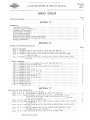
SPRING GROUP Page 1-5 SPECIFICA TIONS • • . . • • . • . . . •
SECTION "A"
GENERAL Assembly of springs. • . . . . . . . . • • • . • .
Auxiliary spring mounting. . • • . . • . • . . .
Cleaning and inspection. . • . . . . . . . • • . .
Disassembly of springs. . . . • . • . • . . . • .
Front spring mounting. . . . . • . • • . . • . • •
Rear spring mounting. . . . . . . • . • . • . . .
Rubber bushed spring mounting (front only).
Rubber bushed spring mounting (rear only).
Spring maintenance. . . . . . . . . . . • . . . • .
.
.
.
•
.
.
.
.
.
.
.
.
.
.
.
.
.
.
.
•
.
•
•
.
•
.
.
.
•
.
.
.
.
.
.
.
•
•
.
.
•
.
.
.
•
• •
. .
. .
. •
. •
• •
. .
• .
. •
.
.
.
.
•
.
.
•
•
•
•
.
•
.
.
.
.
.
.
•
.
.
•
•
.
.
.
.
•
.
.
.
.
.
.
•
.
•
•
•
•
.
.
.
.
.
.
.
•
.
.
•
.
.
.
.
.
•
.
•
.
•
.
•
.
.
.
.
.
.
.
.
.
.
.
.
.
•
•
.
•
.
.
.
.
.
•
.
.
•
.
• .
• •
. .
. .
• .
• .
. .
• .
• •
•
.
•
.
•
•
•
•
.
.
•
.
•
.
.
•
•
.
•
•
•
.
•
•
•
.
•
.
•
.
.
• • . .
.
•
•
. • • . •
2
1
2
2
2
1
2
1
1
SECTION liB"
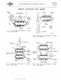
SPRING MOUNTING DIAGRAMS Page FRONT
Fig. 1
Fig. 2
Fig. 3
SPRINGS: - Models L-llO, L-120, LM-l20, L-130, LB-140, LM-150 • . . • . • • • • • •
- Models L-1SO, L-lS3, L-l60, L-163, L-l64, L-165, LC-l60. . . • • • • • •
- Models L-170, L-l73, L-174, L-175, LF-170, L-IBO, L-IB3, L-IB4, L-18S, LC-IBO. • • • . . . . . . . . . . . . . • • • • • . . . • . • • • • • . . . • •
Fig. 4 - Models L-190, L-193, L-194, L-19S, LF-190, L-200, L-204, L-20S, L-210, LF-210. . . . . . • . . . . . • . . . . . . . • . • • . . • . • . . . • . • . • . . . • .
2
REAR SPRINGS: Fig, S - Models L-llO, L-lZO, LM-120, L-130, LB-140, LM-lSO • . • . • . . . • • • • . .
Fig. 6 - Models L-1SO, L-1S3, L-163. • . . . • . • . • • • . . • . • • • • . • . • • • • .
Fig. 7 - Models L-l60, L-l64, L-16S, LC-160, L-170, L-17S. • • • . . . . . • . . . • • • .
Fig. 8 - Models L-l74. • • • . • . • . • . • . . . . . . . . . . . • • . . . • . . • . . . . . • • •
Fig. 9 - Models L-173, L-IB3. . • . • • . . . . . . . . • • • . • • • • • . • . • . • . . . .
Fig. 10- Models L-180, L-IBS, LC-lBO. . • .. . . . . . . • . • . . . . . • . • . • • •
Fig. 11- Models L-193. . . • . . . . • • . • .
. . • • • • . • . • . • . . . . . . . . . • •
Fig. 12- Models L-184, L-190, L-l9S. . ..
. . • • . . . • . . . • . • . • . • • • . • •
Fig. 13- Models L-19S (Timken) • . • . . . . . . . • . . . . .• • . . . . . • . . . .
Fig. 14- Models L-l94, L-200, L-20S. . . . . . . . . . . .
• • • . • . .
Fig. lS- Models L-204.. .
. • . • • • • • . . . • . • . . . ..
• . • . .
Fig. 16 - Models L-2l0. . . . • . . • . • . . • . . • . . . . . • . . . • . • . . . .
Fig. 17- Models LF-170. . . . • .
• . • . . . . . . . • . • • • . • • . . • . . . . . . . • .
Fig. 18- Models LF-190.
. . • . • . . . • . . . . .. • . . . . . . . • . . • • . . .
Fig. 19- Models LF-210. . . . . . . . . . • . • . • • . . . . • . . . • . • . . . • . • . . . • .
2
2
3
3
3
4
4
4
S
S
S
6
6
7
7
1
1
1
SECTION "C"
SHACKLES AND
Figs. 1, 2, 3,
Figs. S, 6, 7,
Figs. 9, 10 Figs. 11, 12
Figs. 13, 14
Figs, 15, 16
Figs. 17, 18
Figs. 19, 20
BRACKETS 4 - Front & Rear for Models L-IIO, L-120, LM-120 . . . . . . . . . •
8 - Front & Rear for Models L-130, LB-14.0, LM-lSO . • . . • . . .
Front for Models L-lSO, L-lS3, L-l60, L-163, L-164, L-165, LC-l60, L-l70, L-l73, L-174, L-l7S, LF-170, L-IBO, L-l83, L-l84, L-IB5, LC-IBO. • . • . • . . . . . • • • . • . • . • • • . • . . .
- Rear for Models L-lS0, L-153 . . . . . . . . . • . • . • . . . • . . . . .
- Rear for Models L-160, L-163, L-164, L-l6S, LC-160, L-170, L-173, L-174, L-17S. . . . . • . . . . . . • . . . • • . • . • . . . . • . . . . . . • •
- Rear for Models L-IBO, L-183,L-IB4, L-18S, LC-l80, L-190, L-193, L-195. . . . • . . . • . • • . . . . . . . . . . • . . . . • • • . . • . . . . •
- Front for Models L-190. L-193, L-194, L-19S, LF-190, L-200, L-204, L-20S, L-210, LF-210. . . . . . . . • . • . . . .
- Rear for Models L-194, L-200, L-204, L-20S, L-210 . . . . • . •
PRJNTEO IN UNITED STATES OF' AMERJCA
1
2
3
3
3
4
4
S
Donated by John & Susan Hansen - For Personal Use Only
Donated by John & Susan Hansen - For Personal Use Only
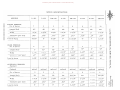
SPRING SPECIFICATIONS
-MODELS
L-110
-~-"
L-120
L-130
LB-140
L-150
L-153 LM-150
---------
FRONT SPRINGS:
No. of leaves
7
-
LM-120
--------
9
Length (flat)
8
9
------ - - - - - - - - - - - -
-------
42"
42"
8
--------
42"
8
8
10
1---
-------------
42"
46" 42" 46" 42"
---------
Width
1-3/4"
-
-
Thickness (per
~af)
1-3/4"
1-3/4"
------
.262"
.262"
.291"
I
1-3/4"
2" 1-3/4" 1-3/4"
2" -----------
---~
.291;1 .323" .323" .291"
3-16/16" 4" 4" 3-7/8"
.291 "
------------
Load to bump
4-3/16"
4"
4-3/8"
4"
3::
~
o
:::0
REAR SPRINGS:
No. of leaves
Length (flat)
8
10
10
8
10 8
10 10
52"
52"
52"
52"
52" 50" 52" -52"
--
----
Width
1-3/4
11
1-3/4"
1-3/4"
2-1/4"
---------------
2-1/4" 2-1/2" 2-1/2
11 (f) 2-1/4"
[Tl :::0
Thickness (per leaf)
Load to bump
.291"
.323"
4-13/16 11
•323"
4-3/8"
4-13/16"
.360"
.360" .401" .401" •36 0" --------
4-3/8"
3-9/16" 4-1/8" 4-1/8 11 4" n<
[Tl
-------
AUXILIARY SPRINGS:
Standard Optional
!
optional
optional
optional
op optional
-------------
No. of leaves
Length (flat)
op
op
optional
-----
-------- - - - -
5
5
5
6
6
8
33"
33"
33"
34" 32-7/8"
33" . . . . . <I . . . . . . . . •• g"'.,. •••
----------
Width
Thicknes s (per leaf)
Load to bump
1-3/4"
1-3/4"
2-1/4" 2-1/4
.262"
.262"
•262"
.262" .262"
.262" 3-3/8"
4-1/8" 3"
32-7/8"
------
11
1-3/4
11
6
3"
-----------,-- ---,
3"
2-1/2" ---------
3"
..
~
. . . . . . . <) 1) .. 2-1/4"
(0
()
~tfl
,.... '1:J
................. .262"
.......... 3-3/8"
---------------
tfl
"0
g~
.,.,.H
....·Z
§
Q
_Ultfl
Donated by John & Susan Hansen - For Personal Use Only
'1:IUlUl
Pl '1:i '1:1
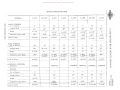
SPRING SPECIFICA TIONS
~~!:J:j
.... H
N~Z
0
n
L-160
L-163
L-164
L-165
L-170
LC-160
L-173
....,.,.Pl
L-174
Ul
o
:;l
til
FRONT SPRINGS:
No. of leaves
Length (flat)
8
8
46"
46"
-
Width
9
9
46"
46 11
-
2-1/4
11
2-1/4"
10
9
9
10
46 11
46"
46"
46"
2-1/4"
2-1/4"
2-1/4"
2-1/4"
Load to bump
2-1/4
2-1/4"
.323"
.323"
.323"
.291"
.323 11
.323 11
.323"
.323 '1
4"
4-5/16 11
3-7/8 11
3-3/4"
3-5/16 11
3-7/16 11
3-1/4"
3-3/8 11
----
I
tz
11
[1l
-
-
Thickness (per leaf)
r
--
s:
o--l
o;;0
I
--l
REAR SPRINGS:
No. of leaves
Length (flat)
8
12
10
8
8
10
14
12
;;0
52"
52 11
52"
52"
52"
52 11
52 11
52"
n
C
7\
-
Width
2-1/2"
2-1/2 11
2-1/2"
Thickness (per leaf)
I
.40 I"
.40111
.401 11
411
5_1/2
4-1/2
3-7/8
Load to bump
,--
2_1/2 11
2-1/2"
2-1/2 11
.401"
.40111
.401"
4-9/16"
6"
5-1/16
[1l
;;0
~---
.401"
11
2-1/2 11
2-1/2"
-
(f)
11
.401"
4-1/8
11
11
<
11
n
s:
[Tl
:J>
AUXILIARY SPRINGS:
Standard
z
standard
standard
standard
standard
standard
standard
r
Optional No. of leaves
6
6
6
6
8
9
Length (flat)
37"
37"
37 11
37 11
38 11
38" 2-1/2"
2-1/2"
2-1/2 11
2-1/2 11
2-1/2 1'
2-1/2" Width
------
-
Thickness (per leaf)
.323 11
411
Load to bump
-
......
~
.....
-
.... -
C
).>
-
.323"
4"
.323"
3-7/8 11
.323 11
--4-1/8"
.201" .291"
-
4-9/16"
5-1/16"
Donated by John & Susan Hansen - For Personal Use Only
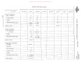
SPRING SPECIFICA TIONS
L-l
MODELS
L-184
L-183
-------
~~~~-
L-185
LC-180
L-190
~~~~~~
FRONT SPRINGS:
No. of leaves
8
12
10
10
11
9
12
9
Length (flat)
46"
46"
46"
46"
46"
46"
46"
52"
2-1/4"
2-1/4"
2-1/4"
2-1/4"
2-1/4"
2-1/4"
2-1/4"
3"
Width
~~
--------
Thickness (per leaf)
--------
.323"
.323"
.323"
.323"
.323"
.323"
.323"
.360"
3-5/16 11
3-5/16 11
3-5/16"
3-5/16"
3-1/2"
3-1/4"
3-5/8"
-----------
Load to bump
3-9/16 11
-----------
t:
r
z[T1
$:
o-l
o
-----------
;.0
-l
REAR SPRINGS:
No. of leaves
10
10
11
13
14
11
11
12
;.0
54"
54"
54"
54"
54"
54"
r;
3"
3"
3"
3"
3"
3"
[T1
8 -.40 1"
3-.360"
8-.401"
3-.360"
•401"
3-1/8"
3-11/1611
3-11 /16"
3-3/8"
standard
standard
standard
standard
----------
Length (flat)
52"
32-1/4"
-------
Width
2-1/2"
3"
~
C
n
tn
;.0
Thicknes s (per leaf)
.401"
8-.447"
2-.401"
3-,447"
10-.401"
8-.401"
3-.3t>0"
----
Load to
.-
AUXILIARY SPRINGS:
Standard
3-11/16"
4-9/16"
6-.401"
8-.3600--
~
~
~
~
n
[T1
--~~~
4-1/4"
<
--------
----~~~
standard
standard
-----------
~~~--
---------
Optional
~~-
No. of leaves
------
7
8
7
9
7
7
39"
41"
---------
Length (flat)
~
Width
2-1/2"
39"
39"
38"
3"
3"
----------
Thicknes s (per Ie
Load to bump
.291"
4-9/16"
39"
----------
~~~~~~~-~
.• 323"
6-.zgpr
3-11/16"
-----------
3"
~~~~~~~-
I~~~
3"
3"
---------
3-.323"
•323"
3-1/8"
3-11/16"
IJl
'0
rtl
n
::;;1Jl
~.
.323"
.323"
'"0
~~
M-H
3-11/16"
3-3/8"
.... ·Z
g
Cl
vorn(fl
Donated by John & Susan Hansen - For Personal Use Only
"0
SPRING SPECIFICATIONS
{lnll
"0
III '0
aq(l)::o
(l) ~_ H
..,.::!'!Z
nO
III
MODELS
L-I93
L-I95
L-194'
LF-190
LC-190
L-200
L-204
L-205
.....
{fl
.".
o
i:l
FRONT SPRINGS:
No. of leaves
Length (flat)
~.
til
9
9
8
9
.......
9
10
9
52"
52"
52"
52"
.•.....
52 '1
52"
52"
3"
........
3
r
r
I
Width
3"
3"
3"
--
Thickness (per leaf)
,401"
.401"
3-3/4"
REAR SPRINGS:
No, of leaves
Width
3-7/16"
--
.401"
........
.401"
.401"
3-7/8 11
3-9/16"
........
3-5/16 11
3-5/8"
3-5/8"
.......
13
16
13
12
12
56"
54"
54"
37-3/4"
--
3" ,360"
13
7-.447"
.5-.401"
3"
-
12
3"
Thickness (per leaf)
-
11
3"
3"
4"
.447"
.401"
9-.447"
3-.401"
.0 •••••
..... 0 ••
..
,.
'" '" '" '"
54"
56"
---3"
3"
,360" 54"
Z
[T1
3:
o-l o
::;0
~
c
n
7:::
3"
(j)
n<
.447"
.447"
.447"
3-1/211
4-7/16 11
3-3/4"
~-
~
[T1
Load to bum.p
3-1/411
4-3/8"
. .
'" '" '" "' '"
-
3:
).>
z
AUXILIARY SPRINGS:
Standard
Optional
standard
I
standard
standard
....... --
8
~-
7
........
8
.......
41"
10
8
41"
41" - --
Length (flat)
Width
Thickness (per leaf)
Load to bum.p
41"
------3"
41"
3"
.......
3"
3"
3" .323"
.323"
.. .. '"
.323"
.323"
.323" 3-1/2 11
4-7/16"
3-1/411
-
"'
4-3/8"
--_
......
__
'"
'" "' . . . III Ii ..
.......
_
c
).>
r
-
-
No. of leaves
standard
standard
3-3/4"
Donated by John & Susan Hansen - For Personal Use Only
SPRING SPECIFICATIONS
L-2IO
LC-200
MODELS
LF-Z10
..
FRONT SPRINGS:
No. of leaves
10
LF-ZZO
L-Z20
-
~
L-225
L-Z30
LF-230
--
10
10
52"
52"
--
52"
Length (nat)
------
---
Width
3"
3"
9-.447"
-r::40I" -
9-.447"
1-.40 I"
. 401"
3-3/4"
3-3/411
3-1/2"
---
Thickness (per leaf)
.-.
---
-------
----
--
3:
o---1
o
--
:;;0
REAR SPRINGS:
No. of leaves
---1
12
15
-
:;;0
-
56"
Length (flat)
C
37-3/4"
---
---
.499"
7':
3"
3"
---
---
n
---
---
Width
Thickness (per leaf)
z
[Tl
--
Load to bump
t:""
C
10-.500"
----~--
-Z-:~3-75"
--
--
(JJ
-
[Tl
:;;0
-- .._ . _ - - - - - '-
n<
4-3/16"
Load to bump
[Tl
3:
-
AUXILIARY SPRINGS:
Standard
»z
c
st=dard :
-
»
r
-
Optional
9
No. of leaves
------
---
-
Length (flat)
41"
Width
3"
Thirknpss (per leaf)
-----------
~
(l)
n
,.- '"d
l::;CIl
3-.401"
6-.360'
'"d()~
---
-
---
P'e:.H
-Z
I7Q
Load to bump
4-3/16"
(l)
....
g Cl
UlUlVl
Donated by John & Susan Hansen - For Personal Use Only
Donated by John & Susan Hansen - For Personal Use Only
L-LlNE MOTOR TRUCK SERVICE MANUAL
SPRINGS
Section A
Page 1
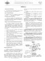
SPRINGS Front Spring Mounting
since this assures the spring leaves being com
pressed.
Front springs are mounted at the front with
brackets and at the rear by shackles.
Rear Spring Mounting
Rear springs are mounted at the front with
brackets and at the rear with shackles.
Auxiliary Spring Mounting
Auxiliary springs are mounted on top of
the main rear spring and under load the auxil
iary spring ends will contact the brackets at
tached to the side rails.
Spring pins on the L-line trucks are of
three types:
1. Spring pins that are threaded into shackles
o;r brackets.
2.
Spring pins that are
into shackles
or brackets.
3.
Spring pins that are
or pressed in
brackets.
Spring pins which are threaded into the
bracket require that the pin be tightened into
the bracket and then backed out one-half turn.
The locknut should then be tightened securely
and the cotter pin installed.
Rubber Bushed Spring Mounting (Rear Only)
On trucks equipped with rubber bushed
spring mountings, it is necessary to remove
the complete spring assembly to replace the
rubber bushings. These rubber bushings are
made up of two parts on each pin. To install
new bushings, the following instructions are to
be used:
1. Remove nuts and washers from bracket
pins at front and rear.
2. Remove U-bolts and slide spring off of both
front and rear bracket pins.
3. Place spring in vise and remove shackle
pin nut and washer.
4. The rubber busnings are separated at the
center of each pin, making it possible to
remove a half of a bushing from each side
of the spring and shackle eye.
5. Install new bushings by reversing the above
operation.
6. Application of soap solution to the bushing
will facilitate installation of the bushings.
NOTE: Do not back off nut to permit in
stallation of cotter pin since this would
permit pin to turn in the bracket, and cause
excessive wear. If necessary, turn pin out
of bracket a slight amount to permit in
stallation of cotter pin when the locknut is
tight.
Spring pins which are to be driven into the
shackle or bracket, require that the pin be
aligned 50 as to be able to install lock bolt
through bracket or shackle with pin in place.
Spring pins that are welded or pressed
into bracket or shackle require that spring pin
nut be tightened securely with knurled side out.
This is a self-lock type nut.
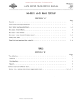
When installing threaded spring pins in
threaded spring shackles, the lubricant hole in
the spring pin should be located in an area ap
proximately 90 0 on either side of top center of
the spring eye or away from the loaded side of
the spring pin (See Fig. 1),
7. When installing nuts on the shackle and
bracket pins, the knurled side of the nut
must face toward the outside.
Tighten
spring and bracket pin nuts securely (ap
proximately 35 ft. lbs.).
eye
Spring Maintenance
Spring
pin
Spring leaf failures at the spring eye are
generally a result of improper spring pin ad
justment. If the pin is drawn up too tightly in
the bracket or shackle, a bind will result.
Spring failures at the center section, or
near the center bolt hole, are generally caused
by loose U-l{olts. These bolts must be kept
tight and checked frequently. The best results
will be obtained by having the vehicle fully
loaded at the time of tightening the U-bolts,
PRINTED IN UNITED STATES
O~
AMERICA
I
{
Lubricant hole
closed,load prevents
proper lubrication
A-23453
Fig. I - Spring Pin Installation (Diagramatic).
With the pin in this position, adequate lubri
cation is assured.
Donated by John & Susan Hansen - For Personal Use Only
SPRINGS
Section A
Page 2
L-UNE MOTOR TRUCK SERVICE MANUAL
Rubber Bushed Spring (Front Spring Only)
Cleaning and Inspection of Springs
To remove rubber bushing from front
springs, the following instructions are to be
used:
Wash or scrub all parts in c
solvent
or clean all parts with steam cleaning equip
ment. Brushing of spring leaves with a wire
brush will facilitate scale removal. (NOTE: Do
not immerse rubber spring bushings in clean
ing solvent.)
(FRONT END)
nut from spring
Remove the
bracket.
2. To remove the front spring pin, remove the
two bolts and nuts that hold the inside half
of the pin bracket to the frame .channel.
This will allow the spring pin to be removed
with the inside half of the spring bracket.
3. Unless replacement of the spring pin is
necessary, do not attempt to drive spring
pin out of bracket. This will damage and
loosen the pin in the inner bracket eye.
1. (REAR END)
To remove the rubber bushings from the
rear end of front
use the following pro
cedure:
1. Remove nuts from both rear spring pins.
2. Remove retainer from pins.
3. This will let the inside shackle be removed
with both shackle
attached.
1. Inspect all spring leaves for breakage and
cracks. Replace defective leaves. Inspect
all leaves for arch by
with new
leaves. If leaves are flattened out, either
re-arch or replace.
2. Examine spring pins for wear. If wear
is apparent, or if pins are corroded or
cracked. replace with new
3. Inspect spring eye bushing, and rear
shackle bushings for wear, and replace if
defective.
4. Inspect spring bracket for breakage and
for wear in mounting bolt, or rivet holes,
and replace if worn or broken.
5. Replace center bolts at each overhaul.
Assembly of Front and Rear Springs
Disassembly of Springs
The disassembly of front or rear springs
is identical in procedure. Disassemble springs
as follows:
I. Lightly coat spring leaves with graphite
grease. Replace spring leaves in proper
order, lining up the center bolt holes.
2. 1. Place spring in vise, clamping assembly
near center of sp
2. Remove nuts from four spring clip bolts,
and remove bolts from clips.
3. Remove nut from
center bolt.
Partially compress spring leaves, and in
sert center bolt and nut.
3. Place spring assembly in vise, and com
press spring leaves fully.
4. Install four spring clip bolts in and install nuts on bolts. bolt nut. 4. Release vise to
leaves to separate.
Remove spring
vise. Separate and
remove leaves from center bolt.
5. Run over end of clip bolts and center bolt
enough to prevent loosening of nut.
Auxiliary Springs
Disassembly of the auxiliary springs dif
fer only slightly from that of the front or rear
springs:
1. Place
leaves together.
in vise, and clamp
Auxiliary Spring Assembly
1. Coat spring leaves lightly with graphite
grease. Place leaves one on top of another
in accordance with length.
2. Straighten tabs of two spring clips, being
careful not to break them off. Heating
clips with a torch will help avoid breakage.
2. Compress spring leaves and install center
bolt and nut.
3. Remove nut from center bolt. and release
vise to permit leaves to separate. Remove
spring from vise.
3. Place spring in vise and compress leaves
fully. Tighten center bolt nut. Bend down
ends of spring clips, being careful not to
break them. Heating the clips with a torch
will facilitate operation.
4. Remove spring leaves from center bolt.
Donated by John & Susan Hansen - For Personal Use Only
SPRINGS
Section B
1
L-UNE MOTOR TRUCK SERVICE MANUAL
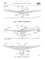
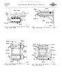
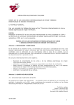
FRONT SPRING MOUNTINGS
Frame rail
Rear bracket
v--
Front bracket
V·bolt
Rubber bushing
Shackle
Wedge plate
r_i.. -~~-E'---___
,.......,
Axle I-beam
A-21S00
FRONT
Fig. I - Models L-IIO I L-120, LM-120, L-130, LB-ILl-O, LM-ISO.
l1li(
Front
U·bolt
Bumper
U·bolt seat
Clip
A-21S14
Fig. 2 - L-ISO, L-JS3, L-160, L-163, L-16Lj., L-16S, LC-160.
Center bolt
U-bolt seat
Lock washer
C::_'-::;'.;f--- Axle
I·beam
FRONT
Fig. 3 - Models l-170, L-173, L-17Lj., L-17S, LF-170, L-180, L-183, L-J8Lj., L-185, LC-IBO.
PRINTEO IN Uf',l,1'£D STATES OF AMERICA
A·21518
Donated by John & Susan Hansen - For Personal Use Only
SPRINGS
Section B
Page 2
L-UNE MOTOR TRUCK SERVICE MANUAL
0( Front
U-bolt seat
Bumper
V·bolt
Center bolt
Lock washer
Wedge
~_~ Axle I·beam
V·bolt nut
FRONT
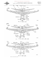
Fig.
~
- Models L-190, L-193,
L-19~,
L-19S, LF-190, L-200,
A-21S13
L-20~,
L-205, L-210, LF-210.
REAR SPRING MOUNTINGS
Rear shackle
Front bracket
Cross member
Rear bracket
A-21S23
REAR
Fig, 5 - Models L-I 10, L-120, LM-120 (Shock Absorbers-Standard)
Absorbers-Optional ).
<
Front
L-130, LB-140, LM-ISO (Shock
V·bolt
~I----l
--,-:---- Spring seat
.....::-:,.::-.--- Axle housing
REAR
"----V·bolt plate
Fig. 6 - Models l- 150, L-153. L-163.
A-21S03
Donated by John & Susan Hansen - For Personal Use Only
L-UNE MOTOR TRUCK SERVJCE MANUAL
V-bolt
Front
V-bolt seat
SPRINGS
Section B
Page 3
Spacer
~"'.:::iI-E,--- Lock washer
Nut -~.:t"t1J:::::.::::.:::::at
, " - - - - V-bolt plate
REAR
A-2J5J6
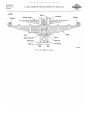
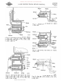
Fig. 7 - Models L-160, L-164, L-165, LC-160, L-170, L-175.
~
V-bolt seat
~ .
Auxiliary spring
Front
Auxiliary center bolt
/
~~:=:~~~~~~~~=~~;i:-=- -~~~~~~=l-c:T~~p=--'~:=:r-'==-'
(6)~o~ "- - - - q~:JQ~C~Ii~P?>t~ '- -r: j~U"'~ "c7JiW'111'---=iU·:~-~-':I;f+,l:~r-l IP--'~~~~[:JEJ=----l~~~~vftp----'
=:;:::=
tL
p
C1.,
Center
oX
bOIt.7/-C~)1R' Spacer
V-bolt
Axle housing
V-bolt plate
--i'(
Spring seat
~
Dowel
Nut
Lock washer
A-2J5J9
REAR
Fig. 8 - Models L-174.
• Front
Clip
~
V-holt
U-bolt seat
a
Center bolt
Spring seat
- Axle housing
V-holt plate ___~--...'\.
Nut
't=~=::::/lF?'TI~_ Lock washer
A-2J5J2
Fig. 9 - Models L-173, L-183.
PRINTED IN UNITED STATES OF AMERICA
Donated by John & Susan Hansen - For Personal Use Only
SPRINGS
Section B
Page 4
«'
L-LINE MOTOR TRUCK SERVICE MANUAL
Front
U·bolt
Clip
U.bolt seat
Center bolt
U.bolt plate
Lock washer
UioE'---- Nut
REAR
A-21510
Fig. 10 - Models L-180, L-185, LC-180.
III(
Front Center bolt Spring seat
!-H---Axle housing
U.bolt plate
Dowel
Lockwasher
LL..I.J""<:""--Nut
A·21517
REAR
Fig. II - Models L-193.
Clip
Front
U.bolt plate
Lock washer
~"""""'--Nut
A.21502
REAR
Fig, 12 - L-18~, L-190, L-J95.
Donated by John & Susan Hansen - For Personal Use Only
L-UNE MOTOR TRUCK SERVICE MANUAL
Clip
Spacer
SPRINGS
Section B
Page 5
U.bolt seat
U.bolt
front
A-21501
Fig. 13 - Models L-19S.
Front
Bushing
Busbing
Axle bousing
A-21742
Fig. 14 - Models L-194, L-200, L-20S.
Front
U·bolt seat
Auxiliary spring
Bushing
ra10~
Clip
'Spring
A-21741
Fig. 15 - Models L-204.
PRINTED IN UNITED STATES OF AMERICA
Donated by John & Susan Hansen - For Personal Use Only
SPRINGS
Section B
Page 6
0(
L-UNE MOTOR TRUCK SERVICE MANUAL
Front
U-bolt seat
Bushing
~Spring
Spring seat Axle housing A-21743
Fig. 16 - Models L-210.
Donated by John & Susan Hansen - For Personal Use Only
SPRINGS
Section C
Page 1
L-UNE MOTOR TRUCK SERVICE MANUAL
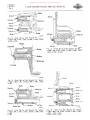
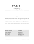
SPRING SHACKLES AND BRAKES
Bracket
~
Rubber bushings
[lL..
___ ~
lu
I
I
-- --f--.--\+
Nut
oval side
Spring
out
A-21S09
Fig. I - Front Spring Front Bracket For
Models
L-IIO, L-120, LM-120.
A-21522
~
Fig, 3 - Rear Spring
'I
Bracket~~,i
Pin
Front Bracket For
Models
L-IIO, L-120, LM-120.
:
I!ri::fl'L
__ --0--
I '
I I'
_..Li.
"
Pin
Nut
'r-.~~...:"'~.~-~......
oval side
out
Rubber bushings
NUl-oval
side oul
,!-oE:.....,..c.~i-i-"-
Shackle
Shackle
Nut
oval side
Washer - - - . , l.....
out
A-21S08
Fig. 2 - Front Spring
Rear Shackle For Models
L-IIO, L-120, LM-120.
PRINTED IN UNIT EO STATES OF' AMERICA
A·21524
Fig.
~
- Rear Spring
L-110, L-120, LM-120.
Rear Shackle
For Models
Donated by John & Susan Hansen - For Personal Use Only
SPRINGS
Section C
Page 2
L-UNE MOTOR TRUCK SERVICE MANUAL
n
Rubber bushings
Nut
ovalside
out
Lubricator
A.22942
Fig. 5 - Front Spring Front Bracket For Models
L-130, LB-lqO, LM-150.
A·23180
Fig. 7 - Rear Spring Front Bracket For Models
L-130, LB-lqO, LM-ISO.
Lock pin
Pin
Nut
ovalside
out
Bracket
Pin
/::...o~-Pin
Nllt---JIIoool'
Bushing
Spring
A·23179
Fig. 6 - Front Spring Rear Shackle For Models
L-130, LB-JijO, LM-ISO.
A·23181
Fig, 8 - Rear Spring Rear Shackle
L-J30, LB-lqO, LM-ISO.
For Models
Donated by John & Susan Hansen - For Personal Use Only
SPRINGS
Section C
Page 3
L-LINE MOTOR TRUCK SERVICE MANUAL
Bushing
Lock pin
A-23446
Bracket
Fig. II • Rear Spring Front Bracket For
L- I50 , L- 153 •
Models
Nut
Shackle pin
Lubricator
A-2151l
Fig. 9 - Front Spring Front Bracket For Models
l-150,l-153, l-160,l-163, l-161t, l-165, lC-160,
l-170,l-173,l-171t, l-175, IF-170, l-180, l-183,
l-181t, l-185, lC-ISO.
~---'--!!'f---
Shackle
pin
Lock pin
Bushings
A-23445
Spring
Rear Shackle For Models
Lock pin Bracket pin .ubricators
Shackle pin
Bushing
A-21506
Fig. 10 - Front Spring Rear Shackle For Models
l-150, l-15a,l-160, L-163, l-161t, l-165,LC-160,
L-170, l-173, L-171t, L-175, LF-170,L-180, L-183,
L-ISIt, l-IS5, LC-ISO.
PRINTED iN UNITED STATES OF" AMERICA
A-2'738
Fig. 13 - Rear Spring Front Bracket For Models
l-160,l-163,L-161t, L-165, lC-160, L-170, L-173,
L-171t, L-175.
Donated by John & Susan Hansen - For Personal Use Only
SPRINGS
Section C
Page 4
L-LINE MOTOR TRUCK SERVICE MANUAL
Bracket
lubricator
Shackle pin
Lock pin
Sbackle
Lubricator
Lock pin--.:J!' Spring~-··
Bushing
Lubricator
A·21139
Fig. l~ - Rear Spring Rear Shackle For
L-160,L-163,L-16~, L-165, LC-160, L-170,
L-17~, L-175.
Models
L-173,
Bracket
Lock pin
A·21505
Fig. 17 - Front Spring Front Bracket For Models
L-190,L-193,L-19~, L-195, LF-190, L-200, L-20~,
L-205, L-210, LF-210.
A·21737
Bracket
Fig. 15 - Rear Spring Front Bracket For Models
L-180, L-183,L-18~, L-185,LC-180, L-190, L-193,
L-195.
Shackle
Bushing
Bushing
Lubricator
Lock pin
l.ubricators
Lock pin
Shackle shaft
A·21135
Fig. 16 - Rear Spring Rear Shackle For Models
L-180,L-183, L-18~, L-185, LC-180, L-190,L-193,
L-195.
A·21520
Fig. 18 - Front Spring Rear Shackle For Models
L-190,L-193,L-19~, L-195, LF-190, L-200, L-20~,
L-205, L-210,LF-210.
Donated by John & Susan Hansen - For Personal Use Only
L-L1NE MOTOR TRUCK SERVICE MANUAL
A-21S2J
Fig. 19 - Rear Spr i ng Front Bracket for
L-194, L-200, L-204, L-205, L-210.
Mode Is
Bushing
cubricator
..,.:..,!-+*--- Shackle pin
Bushing
A·2'S07
Fig. 20 - Rear Spring Rear Shackle For
L-194,L-200,L-204,L-205,L-210.
PAINTED IN UNITED STATES OF AMERle.
Models
SPRINGS
Section C
Page 5
Donated by John & Susan Hansen - For Personal Use Only