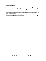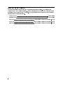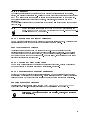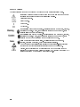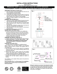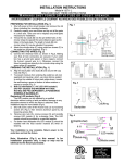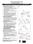
1
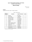
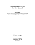
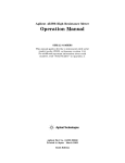
Agilent 16117C Low Noise Test Lead
Operation and Service Manual
Agilent Part No. 16117-90041
Printed in JAPAN July 2001
Fifth Edition
Notice
The information contained in this document is subject to change without notice.
This document contains proprietary information which is protected by copyright. All rights are
reserved. No part of this document may be photocopied, reproduced, or translated to another
language without the prior written consent of the Agilent Technologies.
Agilent Technologies Japan, Ltd.
Component Test PGU-Kobe
1-3-2, Murotani, Nishi-ku, Kobe-shi,
Hyogo, 651-2241 Japan
Warranty
This Agilent Technologies instrument product is warranted against defects in material and
workmanship for a period of one year from the date of shipment, except that in the case of
certain components listed in this manual, the warranty shall be for the specied period. During
the warranty period, Agilent Technologies will, at its option, either repair or replace products
which prove to be defective.
For warranty service or repair, this product must be returned to a service facility designed by
Agilent Technologies. The Buyer shall prepay shipping charges to Agilent Technologies and
Agilent Technologies shall pay shipping charges to return the product to the Buyer. However,
the Buyer shall pay all shipping charges, duties, and taxes for products returned to Agilent
Technologies from another country.
Agilent Technologies warrants that its software and rmware designed by Agilent Technologies
for use with an instrument will execute its programming instruction when property installed on
that instrument. Agilent Technologies does not warrant that the operation of the instrument,
or software, or rmware will be uninterrupted or error free.
Limitation of Warranty
The foregoing warranty shall not apply to defects resulting from improper or inadequate
maintenance by the Buyer, Buyer-supplied software or interfacing, unauthorized modication
or misuse, operation outside of the environmental specications for the product, or improper
site preparation or maintenance.
No other warranty is expressed or implied. Agilent Technologies specically disclaims the
implied warranties of merchantability and tness for a particular purpose.
Certication
The Agilent Technologies certies that this product met its published specications at the
time of shipment from the factory. Agilent Technologies further certies that its calibration
measurements are traceable to the United States National Institute of Standards and
Technology, to the extent allowed by the Institute's calibration facility, or to the calibration
facilities of other International Standards Organization members.
Exclusive Remedies
The remedies provided herein are the buyer's sole and exclusive remedies. Agilent Technologies
shall not be liable for any direct, indirect, special, incidental, or consequential damages,
whether based on contract, tort, or any other legal theory.
Assistance
Product maintenance agreements and other customer assistance agreements are available for
Agilent Technologies products.
If you need assistance, contact your nearest Agilent Technologies Sales and Service Oce.
Addresses are provided at the back of this manual.
c Copyright 1991, 1999, 2000, 2001 Agilent Technologies Japan, Ltd.
Manual Printing History
The manual printing date and part number indicate its current edition. The printing date
changes when a new edition is printed. (Minor corrections and updates which are incorporated
at reprint do not cause the date to change.) The manual part number changes when extensive
technical changes are incorporated.
December 1991 : : : : : : : : : : : : : : : : : : : : : : : : : : : : : : : : : : : : : : : : : : : : : : : : : : : : : : : : : : : : : : : : : : : : : First Edition
February 1999 : : : : : : : : : : : : : : : : : : : : : : : : : : : : : : : : : : : : : : : : : : : : : : : : : : : : : : : : : : : : : : : : : : : : Second Edition
July 1999 : : : : : : : : : : : : : : : : : : : : : : : : : : : : : : : : : : : : : : : : : : : : Third Edition (part number: 16117-90031)
May 2000 : : : : : : : : : : : : : : : : : : : : : : : : : : : : : : : : : : : : : : : : : : Fourth Edition (part number: 16117-90031)
July 2001 : : : : : : : : : : : : : : : : : : : : : : : : : : : : : : : : : : : : : : : : : : : : Fifth Edition (part number: 16117-90041)
iv
Safety Summary
The following general safety precautions must be observed during all phases of operation,
service, and repair of this instrument. Failure to comply with these precautions or with specic
WARNINGS elsewhere in this manual may impair the protection provided by the equipment.
In addition it violates safety standards of design, manufacture, and intended use of the
instrument.
The Agilent Technologies assumes no liability for the customer's failure to comply with these
requirements.
Note
16117C is designed for use in INSTALLATION CATEGORY I according to IEC
61010-1 and POLLUTION DEGREE 1 according to IEC 61010-1 and IEC 60664-1.
16117C is an INDOOR USE product.
Do NOT operate in an Explosive Atmosphere
Do not operate the instrument in the presence of ammable gasses or fumes. Operation of any
electrical instrument in such an environment constitutes a safety hazard.
Keep Away from Live Circuits
Operating personnel must not remove instrument covers. Component replacement and
internal adjustments must be made only by qualied maintenance personnel. Do not replace
components with the power cable connected. Under certain conditions, dangerous voltages
may exist even with the power cable removed. To avoid injury, always disconnect power and
discharge circuits before touching them.
Do NOT Service or Adjust While Alone
Do not attempt internal service or adjustment unless another person, capable of turning o
power and capable of rendering rst aid and resuscitation, is present.
Do NOT Substitute Parts or Modify Instrument
Because of the danger of introducing additional hazards, do not substitute parts or perform
unauthorized modications to the instrument. Return the instrument to a Agilent Technologies
Sales and Service Oce for service and repair to ensure the safety features are maintained.
Dangerous Procedure Warnings
Warnings, such as the example below, precede POTENTIALLY DANGEROUS PROCEDURES
throughout this manual. Instructions contained in the warnings must be followed.
Warning
Dangerous voltages, capable of causing death, are present in this
instrument. Use extreme caution when handling, testing, and adjusting
this instrument.
v
Safety Symbols
General denitions of safety symbols used on equipment or in manuals are listed below.
Instruction manual symbol: the product is marked with this symbol when it is
necessary for the user to refer to the instruction manual.
Alternating current.
Direct current.
On (Supply).
O (Supply).
This Warning sign denotes a hazard. It calls attention to a procedure, practice,
condition or the like, which, if not correctly performed or adhered to, could
result in injury or death to personnel.
This Caution sign denotes a hazard. It calls attention to a procedure, practice,
condition or the like, which, if not correctly performed or adhered to, could
result in damage to or destruction of part or all of the product.
Note denotes important information. It calls attention to a procedure,
practice, condition or the like, which is essential to highlight.
Axed to product containing static sensitive devices use anti-static handling
procedures to prevent electrostatic discharge damage to component.
Caution, risk of electric shock : Terminals which may be supplied from the
interior of the equipment at a voltage exceeding 1 kV, or allow connection to a
voltage exceeding 1 kV are marked with this symbol.
vi
Contents
1. General Information
Introduction . . . . . . . . . .
Using the 16117C . . . . . . .
Product Description . . . . . .
Accessories Supplied . . . . . .
Operating and Safety Precautions
Service . . . . . . . . . . .
Specications . . . . . . . . .
.
.
.
.
.
.
.
.
.
.
.
.
.
.
.
.
.
.
.
.
.
.
.
.
.
.
.
.
.
.
.
.
.
.
.
.
.
.
.
.
.
.
.
.
.
.
.
.
.
.
.
.
.
.
.
.
.
.
.
.
.
.
.
.
.
.
.
.
.
.
.
.
.
.
.
.
.
.
.
.
.
.
.
.
.
.
.
.
.
.
.
.
.
.
.
.
.
.
.
.
.
.
.
.
.
.
.
.
.
.
.
.
.
.
.
.
.
.
.
.
.
.
.
.
.
.
.
.
.
.
.
.
.
.
.
.
.
.
.
.
.
.
.
.
.
.
.
.
.
.
.
.
.
.
.
.
.
.
.
.
.
1-1
1-1
1-1
1-1
1-2
1-2
1-2
Introduction . . . . . . . . . . . . .
Initial Inspection . . . . . . . . . . .
Ambient Environmental Considerations
Operating and Storage . . . . . . .
Connecting the Adapter for Use . . .
Packaging the Adapter . . . . . . . .
.
.
.
.
.
.
.
.
.
.
.
.
.
.
.
.
.
.
.
.
.
.
.
.
.
.
.
.
.
.
.
.
.
.
.
.
.
.
.
.
.
.
.
.
.
.
.
.
.
.
.
.
.
.
.
.
.
.
.
.
.
.
.
.
.
.
.
.
.
.
.
.
.
.
.
.
.
.
.
.
.
.
.
.
.
.
.
.
.
.
.
.
.
.
.
.
.
.
.
.
.
.
.
.
.
.
.
.
.
.
.
.
.
.
.
.
.
.
.
.
2-1
2-1
2-3
2-3
2-3
2-4
Introduction . . . . . . . . . . . . . . . . . .
Making a Custom Test Fixture . . . . . . . . .
Conguration . . . . . . . . . . . . . . . .
Interlock Circuit . . . . . . . . . . . . . . .
Example Conguration of Custom Test Fixture .
Checking Procedure . . . . . . . . . . . . . .
.
.
.
.
.
.
.
.
.
.
.
.
.
.
.
.
.
.
.
.
.
.
.
.
.
.
.
.
.
.
.
.
.
.
.
.
.
.
.
.
.
.
.
.
.
.
.
.
.
.
.
.
.
.
.
.
.
.
.
.
.
.
.
.
.
.
.
.
.
.
.
.
.
.
.
.
.
.
.
.
.
.
.
.
.
.
.
.
.
.
3-1
3-2
3-2
3-3
3-5
3-6
Introduction . . . . . . . . . . . . . . . . . . . . . . . . . . . . . . . . .
Replaceable Parts . . . . . . . . . . . . . . . . . . . . . . . . . . . . . .
4-1
4-1
2. Preparation for Use
3. Operation
4. Service
Contents-1
Figures
2-1.
2-2.
2-3.
3-1.
3-2.
3-3.
3-4.
Product Overview . . . . . . . . . . . . . .
Floating DUT Measurement . . . . . . . . .
Grounded DUT Measurement . . . . . . . .
Adapter Features . . . . . . . . . . . . . .
Floating DUT Measurement Conguration . . .
Interlock cable Assignment (Wiring Side View) .
Example Conguration of Custom Test Fixture .
.
.
.
.
.
.
.
.
.
.
.
.
.
.
.
.
.
.
.
.
.
.
.
.
.
.
.
.
.
.
.
.
.
.
.
.
.
.
.
.
.
.
.
.
.
.
.
.
.
.
.
.
.
.
.
.
.
.
.
.
.
.
.
.
.
.
.
.
.
.
.
.
.
.
.
.
.
.
.
.
.
.
.
.
.
.
.
.
.
.
.
.
.
.
.
.
.
.
.
.
.
.
.
.
.
2-2
2-3
2-4
3-1
3-2
3-3
3-5
.
.
.
.
.
.
.
.
.
.
.
.
.
.
.
.
.
.
.
.
.
.
.
.
.
.
.
.
.
.
.
.
.
.
.
.
.
.
.
.
.
.
.
.
.
.
.
.
.
.
.
.
.
.
.
.
.
.
.
.
.
.
.
.
.
.
.
.
.
.
.
.
.
.
.
1-1
2-2
3-3
3-4
4-1
Tables
1-1.
2-1.
3-1.
3-2.
4-1.
Furnished Accessories . . . . . . . .
Contents . . . . . . . . . . . . . .
Pin Assignment of Interlock Connector
ID Signal Condition . . . . . . . . .
Replaceable Parts List . . . . . . . .
Contents-2
.
.
.
.
.
.
.
.
.
.
.
.
.
.
.
.
.
.
.
.
1
General Information
Introduction
The purpose of this manual is to enable you to use your 16117C Low Noise Test Lead eciently
and condently. This manual contains both general and specic information. To use the 16117C
to perform a specic function (without having to read the entire manual), follow the directions
in \Using the 16117C".
Using the 16117C
The 16117C has been designed to operate specically with the 4339B High Resistance Meter.
To install the 16117C, turn to Chapter 2.
To operate the 16117C, turn to Chapter 3.
To order replaceable parts for the 16117C, turn to \Replaceable Parts" in Chapter 4.
Product Description
The 16117C has been designed to operate specically with the 4339B High Resistance Meter.
The 16117C is used to measure insulation resistance. The 16117C has the following features:
Prepared exclusive connector for the 4339B. This allows easy to make original test xture
for the 4339B
High-voltage safety designed using an interlock circuit
Accessories Supplied
The accessories listed in Table 1-1, are supplied with the 16117C:
Table 1-1. Furnished Accessories
Description
Part Number
Operation and Service Manual
P/N 16117-90041
Quantity
1
General Information
1-1
Operating and Safety Precautions
Service
The voltage levels (up to 1000 V) in this adapter warrants extreme care for operator safety.
Service must be performed only by qualied personnel.
Specications
This section lists the complete 16117C specications. These specications are the performance
standards and limits against which the 16117C is tested. When shipped from the factory, the
16117C meets the specications listed in this section.
Applicable Test Voltage : : : : : : : : : : : : : : : : : : : : : : : : : : : : : : : : : : : : : : : : : : : : : : : : : : : : : : : : 1000 V maximum
Applicable Test Current1 : : : : : : : : : : : : : : : : : : : : : : : : : : : : : : : : : : : : : : : : : : : : : : : : : : : : : : : 10 mA maximum
Applicable Instrument : : : : : : : : : : : : : : : : : : : : : : : : : : : : : : : : : : : : : : : : : : : : : : : : : : : : : : : : : : : : : : : : : : : : : 4339B
Interlock Circuit : : : : : : : : : : : : : : : : : : : : : : : : : : : : : : : : : : : : : : : : : : : : : : : : : : : : : : : : : : : : : : : : : : : : : : : furnished
Cable Length : : : : : : : : : : : : : : : : : : : : : : : : : : : : : : : : : : : : : : : : : : : : : : : : : : : : : : 1 m (connector to connector)
Operating Temperature : : : : : : : : : : : : : : : : : : : : : : : : : : : : : : : : : : : : : : : : : : : : : : : : : : : : : : : : : : : : : : : : 0 to 55 C
Operating Humidity : : : : : : : : : : : : : : : : : : : : : : : : : : : : : : : : : : : : : : : : : : : : : : : : : : : : : : : : : : 70% RH (@40 C)
Non-operating Temperature : : : : : : : : : : : : : : : : : : : : : : : : : : : : : : : : : : : : : : : : : : : : : : : : : : : : : : : : 040 to 70 C
Non-operating Humidity : : : : : : : : : : : : : : : : : : : : : : : : : : : : : : : : : : : : : : : : : : : : : : : : : : : : : : 95% RH (@40 C)
1. Maximum measurable current of the 4339B is 100 A.
1-2
General Information
2
Preparation for Use
Introduction
This chapter explains how to install the 16117C Low Noise Test Lead. The topics covered
include initial inspection, ambient environmental considerations, connecting the adapter for
use, and repackaging the adapter for shipment.
Initial Inspection
The adapter has been carefully inspected electrically and mechanically before being shipped
from the factory. It should be in perfect physical condition, no scratches, dents or the like, and
it should be in perfect electrical condition. Verify this by carefully performing an incoming
inspection to check the adapter for signs of physical damage and missing contents. If any
discrepancy is found, notify the carrier and Agilent Technologies. Your Agilent Technologies
sales oce will arrange for repair and replacement without waiting for the claim to be settled.
1. Inspect the shipping container for damage, and keep the shipping materials until the
incoming inspection is completed.
2. Verify that the shipping container contains everything shown in Figure 2-1 and listed in
Table 2-1.
3. Inspect the exterior of the 16117C for any signs of damage.
Preparation for Use
2-1
Figure 2-1. Product Overview
Table 2-1. Contents
Agilent Part Number
Description
1 Low Noise Test Lead
2 BNC Female-Connector
3 Triaxial Female-Connector
4 Operation and Service Manual1
1 Operation
2-2
16117C
1250-2317
1250-2228
16117-90041
and Service Manual is not shown in Figure 2-1.
Preparation for Use
Quantity
1
1
1
1
Ambient Environmental Considerations
Operating and Storage
The 16117C must be operated within an ambient temperature range of 0 C to +55 C and
relative humidity up to 70% RH at 40 C (non-condensing).
The 16117C may be stored within a temperature range of 040 C to +70 , and at a relative
humidity up to 95% at +40 C (non-condensing).
Connecting the Adapter for Use
The 4339B connection with 16117C has two congurations: oating and grounded DUT
measurement congurations. The connections are dierent for each conguration. The
connections are as shown in Figure 2-2 and Figure 2-3.
Warning
Do NOT touch the electrode and UNKNOWN connector while the High
Voltage indicator is lit which shows the 4339B's output is a high voltage
of up to 1000 Vdc maximum. You must operate after turning o the
voltage source output and you have conrmed the high voltage indicator
is turned o.
Figure 2-2. Floating DUT Measurement
Preparation for Use
2-3
Figure 2-3. Grounded DUT Measurement
Packaging the Adapter
If shipment to a Agilent Technologies service center is required, each adapter should be
repackaged using the original factory packaging materials.
Alteratively, comparable packaging materials may be used. Wrap the adapter in heavy paper
and pack in anti-static plastic packing material. Use sucient shock absorbing material on
all sides of the 16117C to provide a thick, rm cushion and to prevent movement. Seal the
shipping container securely and mark it FRAGILE.
2-4
Preparation for Use
3
Operation
Introduction
This chapter describes the features of the 16117C (see Figure 3-1), and the connection to the
4339B and DUT.
Figure 3-1. Adapter Features
1. BNC cable. This connector provides the source voltage to the 16117C. This is a
high-voltage BNC connector and is not compatible with standard BNC connectors.
2. Triaxial cable. The measured signal is carried on the center conductor of this connector.
3. Interlock cable. This connector enables the interlock function which enables and disables
the application of the source voltage from the 4339B when the interlock line is connected
and disconnected respectively.
4. BNC female-connector.
5. Triaxial female-connector.
Operation
3-1
Making a Custom Test Fixture
This section describes how to make a custom test xture for the 4339B.
When you make a custom test xture using the 16117C, you must observe the
Note
usage guidelines described in this section.
Conguration
The 16117C is provided so the user can make custom test xtures for the 4339B. Figure 3-2
shows an simplied conguration of test xture in oating DUT measurement with the 16117C.
Figure 3-2. Floating DUT Measurement Conguration
The BNC connector provides source voltage up to 1000 V. A triaxial connector is used for the
measured signal path. The triaxial connector's center conductor carries the signal. The inner
shield is a Guard, and the outer shield is the ground. Using a guard circuit eliminates the
external noise to the center conductors. The Guard must extend as close as possible to the DUT
contact, but not connected.
For information about the Grounded DUT measurement conguration, refer to 4339B High
Resistance Meter Operation Manual.
3-2
Operation
Interlock Circuit
The interlock circuit automatically enables interlocking the source voltage and current limit
function. To enable this function in your custom test xture, the 16117C provides an interlock
cable. This section describes how to use interlock circuit to meet your custom test xture
requirements.
Figure 3-3 shows pin assignments for the interlock cable.
Figure 3-3. Interlock cable Assignment (Wiring Side View)
The interlock cable has six lines. The 4339B changes some settings: Voltage Output, Current
Limit, and Resistivity Mode, depending on the interlock status. Table 3-1, describes the role of
each line:
Table 3-1. Pin Assignment of Interlock Connector
Pin
Name
Description
Interlock
Interrupt signal Disable or enable Voltage Output1
ID1
State signal2
Identicate Test Fixture
ID2
ID3
Special Signal State signal
used for 16008B
switching s and v3
GND
Ground
Connected to Chassis
1
When Interlock line is grounded, voltage output is enabled.
2
Refer to Table 3-2.
3
When the special signal line is grounded, the
v (RV) mode
is selected.
Operation
3-3
The ID signals are used by the 4339B to identify the current limit and the output voltage
performance requested by the test xture. The 4339B is programmed beforehand to change the
current limit and output voltage settings according to the ID line status. The ID status, test
xture identication, and the 4339B current limit and output voltage correspondence is listed
in Table 3-2.
Table 3-2. ID Signal Condition
Description
IDs Condition
Test Fixture
ID3 ID2 ID1
GND
GND
GND
GND
GND
GND
Open
Open
GND
Open
GND
Open
Open
Open
Open
Open
GND
GND
Open
Open
GND
Open
GND
Open
16339A
16008B
16117B
04339-65005
No Limitation
No Limitation
Current Limit: 0.5 mA
100 V maximum
Current Limit: 1 mA
Not Applicable (n/a) Not Used No Voltage output
N/A
N/A
N/A
All IDs are opened
No Voltage output
By grounding all ID lines, the 4339B has no set current and output voltage limitations other
than the current and output voltage limits of the 4339B itself. In which case, if the Interlock
line is grounded, the 4339B can apply a source voltage of up to 1000 V. If the interlock
connector is not connected, all ID lines are all open, so, the 4339B will not apply a source
voltage.
3-4
Operation
Example Conguration of Custom Test Fixture
Warning
Agilent Technologies shall NOT LIABLE for any damages or dangers to the
operator incurred on use of a customized product except for the 16117C
itself. Follow the instructions in following example of making test xture
the operator can operate safely for high voltage measurements.
Figure 3-4 shows an example of test xture conguration. This example shows the test xture
for measuring insulation resistance. This custom test xture has a cover for contacting the
DUT, and the source voltage is interlocked with open and close of this cover.
Figure 3-4. Example Conguration of Custom Test Fixture
Center conductor of BNC connector and center conductor of triaxial connector is connected to
contact of DUT. A source voltage of up to 1000 V is applied these lines and the inner shield of
triaxial connector. So, you must use cable which can withstand a voltage greater than 1000 V.
The inner shield of the triaxial connector is extended close to the DUT contact as a guard line.
Warning
You must design the test xture so the operator can not touch the points
which are indicated or the dangerous voltage symbol in Figure 3-4, to
avoid electrical hazards to the operator. Specially, around the electrodes
should be protected with a cover which is interlocked with source voltage
output.
Operation
3-5
Interlock lines are congured as,
No current and source voltage limitation
All ID lines are connected to ground.
Interlocking the source voltage output with open and close the cover of test xture
Interlock switch is connected in series to Interlock line (brown). This switch turns on and o
together with opening and closing the cover of the customized test xture.
Note
It is recommended that interlock line should have two or more switches. This is
eective to avoid unexpectedly applying source voltage due to trouble with the
interlock switch.
Automatic resistivity mode change is not used
Special Signal line (black) is not connected
Note
The end of unconnected line should be covered with insulations to avoid
contact to ground.
Checking Procedure
The 16117C and the 4339B is operated with high voltage up to 1000 V. These products are
designed that operator can measure safely. To keep safety condition, you must execute
following checking procedure periodically.
This procedure assumes your xture has top cover interlocing source voltage output of the
4339B.
Warning
Do NOT touch the electrode and UNKNOWN connector while the High
Voltage indicator is lit which shows the 4339B's output is a high voltage
of up to 1000 Vdc maximum. You must operate after turning o the
voltage source output and you have conrmed the high voltage indicator
is turned o.
Daily Safety Verication Procedure
1.
2.
3.
4.
Connect the your xture to the 4339B.
Close the top cover of your xture.
Set source voltage to 42 V.
Press V output key of the 4339B.
Conrm that the V output indicator and the High Voltage indicator turn on.
5. Open top cover of your xure.
Conrm that the High Voltage indicator turnes o immediately.
6. Close the top cover again.
Conrm that the High Voltage indicator still turns o.
If you encountered any errors in checking procedure, contact your nearest Agilent Technologies
Oce.
3-6
Operation
4
Service
Introduction
This chapter gives the replaceable parts information for the 16117C.
Replaceable Parts
Table 4-1 identify the replaceable parts. Do not disassemble the 16117C any further than
shown in Table 4-1. The listed parts can be ordered from your nearest Agilent Technologies
Oce. Ordering information should include the Agilent part number and the quantity required.
Table 4-1. Replaceable Parts List
Agilent Part
Number
16117-87102
16117-40001
16117-40002
16117-87103
16117-87104
16117-61604
16117-61605
16117-61606
3050-0891
0515-1552
1250-2228
1250-2317
16117-90041
1 not
1
1
1
2
1
1
1
1
2
2
1
1
1
Description
Model Label
Holder
Holder (with Nuts)1
Warning Label (Red) on BNC and Triaxial cable
Label (Yellow) on Interlock cable
Cable Assembly (Triaxial)2
Cable Assembly (BNC)2
Cable Assembly (Interlock)2
Washer Flat to x a holder
Screw Pan Head to x a holder
Triaxial Connector Female
BNC Connector Female
Operation and Service Manual
including a model label.
2 including
Warning
Qty.
a warning label and a cable tie.
These servicing instructions are for use by qualied personnel only. Do
NOT perform any servicing other than that contained in the operating
section unless you are qualied to do so.
Service
4-1