1
Service Manual
RA-SB0003 EN
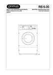
Pneumatic Disc Brake
Bendix ADB 3700 / ADB 4300
(for IVECO Commercial Vehicles)
KNORR-BREMSE
Systeme für Nutzfahrzeuge
Table of Contents
Page
4
5
7
7
7
8
8
1
1.1
1.2
1.2.1
1.2.2
1.2.3
1.2.4
Exploded view of brake
Service kits for Bendix ADB 3700/4300
Brake discs and pads
General notes
Measurement of brake discs and pads
Wear limits of Brake Discs
Notes on Brake Discs for the ADB 4300
2
2.1
2.2
2.3
2.4
General information
Brake data
Lubricants
Torque requirements
Tools
3
3.1
3.2
3.2.1
3.2.2
3.2.3
Description and Function
Sectional drawing
Description of operation
Brake application
Brake release
Brake adjustment (automatic)
10
11
11
11
11
4
Safety instructions for service work
11
5
Brake Inspection
12
6
6.1
6.2
Brake pad check
Brake pad thickness
Uneven Pad Wear
13
13
7
Pad removal
14
8
Pad installation
16
9
Setting of running clearance (Pad to Disc)
16
10
Final Checks
17
11
Check of the automatic adjustment function
18
12
12.1
12.2
12.3
Replacement of Brake Chamber
General
Removal of Brake Chamber
Installation of Brake Chamber
19
21
22
13
13.1
13.2
Replacement of Brake Caliper
Removal of Brake Caliper
Installation of Brake Caliper
24
25
14
14.1
14.2
14.3
Repair of removed Brake Caliper
Replacement of Brake Caliper Guide Pin Seals
Replacement of Adjuster Boot
Replacement of Adjuster Assembly
26
27
28
15
15.1
15.2
Replacement of Wedge Assembly
"Old" version Caliper
"New" version Caliper
29
29
Notes
30
9
9
9
9
3
1
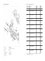
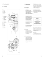
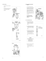
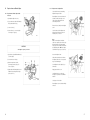
Exploded view of brake
1
2
3
4
5
6
7
8
9
10
11
4
Caliper
Carrier
Brake actuator
Bush
Guide pin
Boot
Guide pin retaining bolt
Resilient mount
Boot assembly
Guide bolt
Pad retainer, assy.
12
13
14
14/4
15
16
17
18
19
20
1.1
Brake pads
Wedge assembly
Brake adjustment mechanism with boot
Boot
Thrust plate
Fork
Boot assembly
Boot assembly
Wire spring
Wear indicator
Service kits for “Bendix ADB 3700 / 4300”
KNORR-BREMSE
Service Kit No.
Description
Contains
Item No's
For Brake
Type No.
381.391
Guide Pin Kit (no seals) (Caliper set)
4, 5, 7, 8, 10
All Types
381.412
Wear Indicator Kit (Axle set)
20
131.766
131.767
131.720
131.721
381.425
Wear Indicator Kit (Axle set)
20
131.790
131.791
131.774
131.775
381.413
Seal Kit (Caliper set)
6, 9, 17, 18, 14/4
All Types
381.419
Pad Retainer Kit (Caliper set)
11, 16, 19
131.720
131.721
131.774
131.775
381.422
Pad Retainer Kit (Caliper set)
11, 16, 19
131.766
131.767
131.790
131.791
381.426
Wedge Assembly (Caliper set)
13
131.766*)
131.767*)
131.790
131.791
381.427
Wedge Assembly (Caliper set)
13
131.720*)
131.721*)
131.774
131.775
381.428
Adjuster Assembly (Caliper set)
14
131.766
131.767
131.790
131.791
381.429
Adjuster Assembly (Caliper set)
14
131.720
131.721
131.774
131.775
II 32955
Brake Pads with Pad Retainers
(Axle set for ADB 3700)
11, 12, 16, 19
131.766
131.767
131.790
131.791
II 32957
Brake Pads with Pad Retainers
(Axle set for ADB 4300)
11, 12, 16, 19
131.720
131.721
131.774
131.775
*) Only suitable if the original Wedge and Brake Chamber Assembly have been replaced with the
"Clip" Type Brake Chamber – see Section 12
5
KNORR-BREMSE
Service Kit No.
Description
Contains
Item No's
For Brake
Type No.
II 33683
II 33684
II 33685
II 33686
II 33687
T 18 Brake Chamber (with Wedge Assy.)
T 20 Brake Chamber (with Wedge Assy.)
T 22 Brake Chamber (with Wedge Assy.)
T 24 Brake Chamber (with Wedge Assy.)
T 27 Brake Chamber (with Wedge Assy.)
3, 13
3, 13
3, 13
3, 13
3, 13
131.766*)
131.767*)
II 33688
II 33689
II 33690
II 33691
T 18 Brake Chamber (with Wedge Assy.)
T 20 Brake Chamber (with Wedge Assy.)
T 22 Brake Chamber (with Wedge Assy.)
T 24 Brake Chamber (with Wedge Assy.)
3, 13
3, 13
3, 13
3, 13
131.720*)
131.721*)
II 37371
II 37372
II 37373
II 37374
II 37375
T 18 Brake Chamber (Clip Type)
T 20 Brake Chamber (Clip Type)
T 22 Brake Chamber (Clip Type)
T 24 Brake Chamber (Clip Type)
T 27 Brake Chamber (Clip Type)
3
3
3
3
3
131.790
131.791
131.774
131.775
II 33692
Pad Retention Pins and Clips Kit
(Axle set)
11 (Pins & Clips only)
All Types
II 33693
Clip for Brake Chamber (2 off)
(not pictured)
All Types
II 34564
Pad Locating Pins and Retainer Spring Kit
(Axle set)
(not pictured)
All Types
Boot for Adjuster (Axle set)
14/4
All Types
II 37400
1.2
Brake discs and pads
1.2.1
General notes
The replacement of brake discs and pads
is subject to the specifications of the
respective vehicle manufacturer.
When replacing brake discs, make sure
that the correct screw fittings are used
and observe the specified bolt tightening
torques (refer to Section 2.3 and to IVECO
manual).
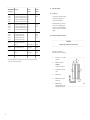
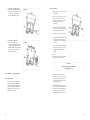
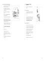
1.2.2
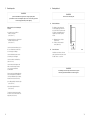
Measurement of brake discs and pads
WARNING!
For optimum safety, stay within the Disc and Pad wear limits.
Dimensions refer to ADB 4300.
Dimensions in brackets refer to ADB 3700.
A
=
Disc thickness – new condition –
50 (45) mm
B
=
Minimum Disc thickness –
47 (42) mm
The disc must be replaced!
C
=
Overall thickness of new Pad
25 mm
D
=
Backplate 7 mm
E
=
Minimum thickness of friction
material 2 mm
F
=
Minimum thickness
brake pad + backplate 9.0 mm;
brake pads must be replaced
*) If the original Wedge and Brake Chamber Assembly have been replaced with the "Clip" Type Brake
Chamber, the "Clip" type must be used again.
6
7
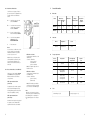
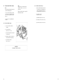
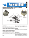
1.2.3
Wear limits of Brake Discs
Check Disc at each change of Pads for
grooves and cracks. The diagramm shows
possible conditions of the Brake disc
surface.
2
General Information
2.1
Brake data
Brake
A1
=
Small cracks spread over the
surface are allowed
B1
=
Cracks less than 1.5 mm deep
or wide, running in a Radial
direction, are allowed
C1
=
Grooves (circumferencial) less
than 1.5 mm wide are allowed
D1
=
Cracks in the vanes are not
allowed and the Disc
MUST BE REPLACED.
a
=
Wheel size
Weight
without actuator
Pad to Disc
Running
clearance
ADB 4300
430
50
22.5”
57 kg
0.9-1.2 mm
ADB 3700
370
45
19.5”
45 kg
0.9-1.2 mm
Lubricants
Part no.
Designation
Colour
423.243
Shell Darina R2
yellow
Pad Contact area
Notes:
In case of surface conditions A1 to C1 the
disc can continue to be used until the
maximum wear limit B = 47 (42) mm is
reached – see Section 1.2.2.
Machine the faces of the brake disc in
conformity with the specifications of the
respective vehicle manufacturer. The
brake disc must be machined evenly on
both sides.
1.2.4
2.2
Brake discs
dia. mm
thickness
mm
• IVECO kit no 1908729
(for replacement of Brake Discs of the
“old” version)
Contents: 2 Brake Discs
(part no. 7180177)
24 bolts M16x80
(part no. 16683434)
Note: The repair kit replaces the old
Brake Disc version.
2.3
Torque requirements
Item no.
(refer 3.1)
Designation
Bolt tightening
torque in Nm
Spanner
size
10
Guide Bolt
300 ± 20
24 mm
7
Guide Pin Retaining Bolt
400 ± 40
32 mm
Brake Chamber
Mounting Nuts
100 ± 10
24 mm
brake carrier/
steering knuckle
4 hexagon bolts
615 ± 60
30 mm
brake disc/hub
280 ± 13
18 mm
Notes on Brake Discs for the ADB 4300
Vehicles up to chassis numbers 4165557
or C014648 have been equipped with
Brake Discs with smooth continuous
cooling channels.
IVECO part number 19076341
(old version):
If required, these discs must be replaced
by the version with interrupted cooling
channels (pillar design). Since they have a
reduced susceptibility to cracking.
IVECO part number 7180177
(new version):
• IVECO kit no. 1908614
(for replacement of the Brake Discs of
the “new” version)
Contents: 2 Brake Discs
(part no. 7180177)
(without bolts)
Note: This kit had been provided for
vehicles where the discs have already
been converted to the "new" design.
2.4
Note:
Brake discs of the new version (part no.
7180177) may only be installed with "long"
bolts M16x80 (part no. 16683434). For
bolt tightening torques refer to Chapter
2.3.
Tools
dismantling tool (2 off)
II 33905 (see pages 19 - 23)
As brake discs and pads are only replaced
in complete sets, the following IVECO
repair kits for Brake Discs are available:
8
9
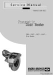
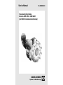
3
Description and Function
3.1
Sectional drawing
3.2
3.2.1
Legend:
1
1/1
1/2
2
3/1
3/2
3/3
7
10
11
12
12/1
12/2
13/1
13/2
14
15
16
20
Caliper
Fixed ramp
Movable ramp
Carrier
Brake Chamber
Boot
Push rod
Guide pin retaining bolt
(primary guidance)
Guide bolt
(secondary guidance)
Pad retainer, assy.
Brake Pads
Inboard Brake Pad
Outboard Brake Pad
Wedge
Roller set
Adjuster assy.
Thrust plate
Fork
Wear indicator
Description of operation
(Floating Caliper principle)
4 Safety Instructions for service work
Brake application
Please also refer to the relevant safety instructions
for repair work on commercial vehicles, especially
for jacking up and securing the vehicle.
Refering to Fig. 3.1
Use only original KNORR-BREMSE parts.
When applying the brake, the brake
pressure P causes the piston rod force (F1)
of the Brake Chamber (3/1) to be
transmitted to a wedge assembly equipped
with two rollers (13/2).
Please follow repair manual instructions and
adhere to the wear limits of the Pads and the Disc
– see Section 1.2.2 and 6.
One of the rollers is supported by a fixed
ramp (1/1), whereas the second roller
displaces a movable ramp (1/2) in an axial
direction giving an increased application
force (F2). This force (F2) is then
transmitted, through an integral adjuster
assembly (14) and an intermediate Thrust
Plate (15), to the inboard brake pad (12/1)
and, through the brake caliper, to the
outboard brake pad (12/2).
Tighten bolts and nuts to the recommended
torque values – see Section 2.3.
WARNING!
Pads must be changed as an axle set
and NOT individually.
Use only Pads which are permitted by
the vehicle manufacturer.
Failure to comply with this may invalidate the
Vehicle Manufacturer’s Warranty
The contact pressure between the brake
pads (12) and the brake disc generates
the braking torque for the wheel.
3.2.2
Brake release
As the braking pressure P is reduced,
springs inside the brake as well as inside the
Brake Chamber cause the wedge unit to
resume its initial position.
3.2.3
After re-fitting the wheel according to the Vehicle
Manufacturer’s recommendations, please ensure
that there is sufficient clearance between the Tyre
Inflation Valve, the Caliper and the wheel rim, to
avoid damage to the Valve.
After service work:
Check the brake performance and the system
behaviour on a rolling road or by actual road test.
Brake adjustment (automatic)
To maintain a constant running clearance
between the brake pads and the brake
disc, the brake is equipped with a lowwearing automatic adjusting mechanism
(14). This operates when pad wear had
taken place.,
10
11
5
Brake Inspection
6
Brake pad check
WARNING!
WARNING!
If these recommendations are ignored, there is a danger of brake failure.
If the Pads are worn down to the backplate or if Disc wear is excessive, brake performance
will be severely affected and may be lost completely.
Observe the wear limits of the pads.
6.1
Make a visual check of the brake pads
in order to
The thickness of the pads must be
checked regularly, dependent on the
usage of the vehicle. The pads must be
checked in conformity with any legal
regulations, but at least every three
months.
a) ascertain the wear condition or
thickness of the pads
(refer Section 1.2);
b) compare the thicknesses of the inboard
and outboard pads of a brake
(refer Section 6.2).
Check the electrical wear indicator (20) for
its correct fit and make sure that it does
not show any signs of damage.
Check the visible rubber parts to make
sure that they are not damaged.
Brake Pad thickness
A = Minimum thickness of friction
material 2 mm
B = Thickness of friction material
18 mm (when new)
6.2
Uneven Pad wear
If the difference in thickness of the two
pads is greater than 4 mm, brake checks
should be made – see Section 5.
Check the condition of the Brake Discs
(refer Section 1.2.2).
Check the wheel hub for tightness and
make sure that its bearing clearance is
correct to vehicle manufacturers
recommendation.
If there are any signs indicating malfunction,
such as uneven pad wear, pad distortion
or if a high residual brake torque is evident,
the brakes must be checked to verify:
WARNING!
To avoid damage to the Disc surfaces, the Pads must to be replaced
when 2mm of friction material thickness is reached at any point.
a) the sliding capability of the brake caliper
(refer Section 7.8)
b) the automatic adjustment function
(refer Section 11).
The inside of the brake caliper should be
checked for corrosion after removal of the
wedge unit (refer Section 12).
12
13
7
Pad removal
The road wheel must be removed.
7.1
Remove the connection cable of the Pad
Wear Indicator (20).
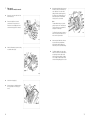
7.2
Remove the Split Pin 11/1 from the
retention bar 11/2. Depress the Pad
Retainer 11/3 and carefully push out the
retention bar noting positions of washers.
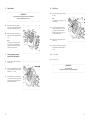
7.6
By displacing the Brake Caliper (1) toward
the vehicle centre, the Thrust Plaste (15)
can be pulled out of its location. After
pulling out the inboard brake pad (12/1),
the Caliper can be slid toward the road
wheel, whereupon the outboard Brake
Pad (12/2) can also be removed.
Note:
The inboard Brake Pad (12/1) is held in
place by two pins to the Thrust Plate (15).
These insert in the bores provided in the
backplate of the brake pad.
The Thrust Plate (15) must be checked for
wear at its contact points. Wear of more
than 0.4 mm is not permissible.
7.3
After removing the Brake Pads, dirt must
be removed from the pad abutments
which, together with the rubber parts,
must be inspected for any visible damage.
7.8
The sliding capability of the brake caliper
must be checked. Care should be taken to
not trap fingers and the caliper should
slide freely along the guide pins. If sliding
forces are high, the brake caliper must be
removed and the guiding system checked.
Lift the Pad Retainer (11/3) and the locking
mechanism retainer (11/4).
7.4
Unhook the wire spring (19).
7.5
Rotate the hexagon of the Adjuster (14) to
its stop by means of the Fork (16) (see
arrow).
14
7.7
15
8
Pad installation
IMPORTANT!
10
Final Checks
10.1
Connect the wire spring (19) to retain the
Fork (16).
Use only new Genuine pads, approved by the vehicle manufacturer.
Replace brake pads only as an axle set.
8.1
8.2
Move the brake caliper (1) toward the
vehicle centre, then install the Thrust Plate
(15) and the inboard Brake Pad (12/1).
Note:
The spring presses the Fork (16) on to the
Thrust Plate (15).
10.2
Insert the locking mechanism retainer
(11/4) into the small groove in the Fork
(16). Lower the Pad Retainer with the
spring (11/3) and secure by means of a
retention bar and split pin.
10.3
Attach the connecting cable to the wear
indicator (20).
10.4
Operate the vehicles brakes several times
and manually check the freewheeling of
the hub.
10.5
Re-Fit road wheel.
10.6
Perform a test run.
Move the brake caliper toward the road
wheel and install the outboard Brake Pad
(12/2).
Note:
The two pins of the Thrust Plate must
insert into the bores of the Brake Pad
backplate. The Thrust Plate and Brake
Pads must be freely movable.
9
Setting of running clearance
between Brake Pad and Disc
9.1
Firmly move brake caliper (1) toward the
vehicle centre.
IMPORTANT!
9.2
Insert a feeler gauge between the inboard
pad (12/1) and the brake disc (specified
dimension: 1.2 + 0.2 mm).
9.3
Turn the Adjuster (14) screw by using the
Fork (16) such that the feeler gauge is tight.
Pull out the feeler gauge and check that
the wheel hub rotates freely.
16
Bed in new brake pads.
Initially avoid long duration or heavy brake applications.
17
11
Check of the automatic adjusting
function
11.1
Remove the pad retainer as per Section
7.1 to 7.3.
11.2
For checking the automatic adjusting
function, a running clearance between the
brake pad and disc of > 2 mm is required.
See Section 9.2 for checking. This should
be set by rotating the Fork (16) – see
Section 9.3.
11.3
Actuate the brake about ten times with low
pressure (about 2 bar).
12
Replacement of Brake Chamber
12.1
General
Since the brake was introduced the design
of the Push Rod connecting the Brake
Chamber to the Wedge Assembly has
been modified.
At the time of change, the Part Number
Label was changed as below and this will
allow identification of the Caliper as an
"Old" version or a "New" version.
12.1.1 "Old" Version
11.4
Again measure the running clearance .
The "Old" version used a "No Clip" version
Push Rod (Figure A).
Wedge Assembly supplied as part of
Brake Chamber.
If the running clearance has reduced
notably, the automatic adjusting function is
working correctly. Running clearance
values between 0.6 and 1.2 mm are
permissible.
Figure A
Note:
The "No Clip" version may have been
replaced at an earlier service by a "Clip"
version (see below).
IMPORTANT!
Running clearance values that are smaller than 0.6 mm may cause
rubbing or hot running of the brake.
If the automatic adjusting function of the brake caliper
is not working, the Adjuster Mechanism or Caliper must be replaced.
18
19
12.1.2 "New" Version
12.1.3 Notes regarding changing of Brake
Chambers
The "New" version uses a "Clip" version
(Figure B).
On account of the increased Service
Return Spring force introduced into Brake
Chambers after Feb. 1995 (Week Date
Code 0895), checks should be made of
the date codes on both Disc Brake
Chambers of the vehicle. In the event that
either shows a date code before this, it is
recommended that both Brake Chambers
are replaced.
Wedge Assembly supplied as part of the
Caliper. Brake Chamber available
separately.
It is important that both Brake
Chambers have the same Return
Spring force.
12.2
Removal of Brake Chamber
a) disconnect both nuts (3/4) from the
threaded bolts of the brake actuator
and remove them together with the
washers;
b) charge brake actuator with compressed
air (2 bar max.) to obtain the greatest
possible piston stroke for the following
tasks;
c) introduce a safety tool II33905 (spacer
tube) between the brake actuator flange
and the brake caliper flange to ensure
that the return spring remains compressed and the working space is kept
free;
CAUTION!
The dismantling tool must be correctly
positioned, since otherwise
the hands might get squeezed.
Figure B
d) pull the Boot (3/2) away from the Push
Plate to expose the Push Rod
(see Figure A and Figure B on Page 19
and 20).
21
20
e) If the unit is a "No Clip" version.
Remove the Dismantling Tool. Exhaust
the Brake Chamber. Disconnect the air
hose. Remove complete Brake
Chamber and Wedge Assembly.
12.3.2 "Clip" Version
Figure A
a) Remove plastic protection cap from the
brake actuator;
b) remove boot (3/2) to get access to the
groove for the clip (3/6); introduce a
new clip into the groove of the thrust
rod (3/3) by means of a small
screwdriver;
c) rub grease ("Shell Darina R2") into the
grooves of the boot and return the latter
into the right installation position;
d) connect air hose to the brake actuator;
f) If the unit is a "Clip" version.
Remove the Clip with a small
screwdriver. Pull the Brake Chamber
out of the Wedge Assembly. Remove
the Dismantling Tool. Exhaust the Brake
Chamber. Disconnect the air hose.
Remove Brake Chamber.
Figure B
e) charge brake actuator with compressed
air (2 bar max.) to obtain the greatest
possible piston stroke for the following
operations;
f) press brake actuator into the thrust rod
until the clip engages; check correct fit
by lightly exerting a light pull on the
actuator.
Note:
If you pull too strongly, the wedge support
is placed out of its correct position;
CAUTION!
Do not slide your fingers between the flanges.
They might get squeezed.
12.3
Installation of a new Brake Chamber
12.3.1 "No Clip" Version
Remove plastic protection cap from the
assembly. Insert the assembly into the
Caliper. Screw both nuts (3/4) with washer
onto the threaded bolts of the Brake
Chamber (see Section 2.3 for Torque
settings). Connect air hose.
22
g) place the brake actuator into right
position in relation to the air connection
and the bores of the two bolts; then
exhaust the actuator. Ensure that the
bolts slide into the bores;
h) press the brake actuator against the
flange of the caliper and screw both nuts
with washers onto the threaded bolts of
the brake actuator (for specified bolt
tightening torque refer to Section 2.3).
23
13
Replacement of Brake Caliper
Note:
Check type plates of the Brake Caliper
and Brake Chamber to ensure correct
replacement.
Note:
When replacing the Brake Caliper, please
observe the following points:
Replacement Brake Calipers are supplied
without Brake Chamber.
On account of design changes made in
October 1994, only Calipers with a Date
Code J4 or later should be used (refere
page 20).
13.2
Installation of Brake Caliper
a) Fasten the Brake Caliper (1) and Carrier
(2) assembly to the steering knuckle by
means of hexagon head bolts (21). For
bolt tightening torques refer Chapter 2.3;
b) install Brake Chamber
(refer Section 12.3);
c) install Brake Pads (refer Section 8);
See Sections 12.1.3. regarding Brake
Chambers.
d) set running clearance (refer Section 9);
e) perform final checks (refer Section 10).
13.1
Removal of Brake Caliper
a) disconnect air line from Brake
Chamber;
b) remove Brake Pads
(refer Sections 7.1 to 7.6);
c) remove hexagon head bolts (21) from
the brake carrier;
d) take Brake Caliper (1) and Carrier (2)
assembly off the steering knuckle;
e) remove Brake Chamber
(refer Section 12).
CAUTION!
The Caliper is very heavy – take care!
24
25
14
Repair of removed Brake Caliper
14.1
Replacement of Brake Caliper Guide
Pin Seals
14.2
Replacement of Adjuster Boot
Clean road dirt from area surrounding
Adjuster Hexagon and Boot.
Rotate Adjuster Screw several turns anticlockwise and lever Boot edge out of
Caliper housing. Rotate further and
remove Adjuster Screw.
a) clamp Brake Caliper into a vice;
b) loosen and remove Guide Pin Retaining
Bolt (7) and Guide Bolt (10);
Remove the boot (14/4) from the Adjuster
screw.
c) remove Carrier (2);
d) remove Boots (6, 9, 17, and 18) (also
refer to figure on page 4);
Check the threads of the Adjuster and
inside the Brake Caliper as well as all
movable parts, for corrosion.
CAUTION!
The Caliper is very heavy – take care!
e) press Bushes (4) and Resilient Mount (8)
out of the Caliper;
f) clean bush bores in Caliper;
g) install new parts from Seal Kit;
performing operations (b) to (e) in
reverse sequence;
h) tighten Guide Pin Retaining Bolt (7) and
Guide Bolt (10) with specified torques
(refer Section 2.3).
Note:
Make sure that all parts of the Brake
Caliper are completely clean. Remove any
dirt particles with a rag moistened with
isopropyl alcohol (or similar solvent). When
assembling the parts, ONLY use original
"Shell Darina R2" grease (see Section 2.2).
Grease the Adjuster Screw.
Slide new Boot (14/4) from Seal Kit onto
the Adjuster; and ensure correctly seated
in groove behind hexagon.
Screw Adjuster into the Caliper (1) by a
few threads.
Lightly grease the Boot seat.
Carefully drive the boot seat into the
housing bore by means of an aluminium
mandrel.
Check proper fit of the Boot.
Rotate Adjuster Screw clockwise until fully
retracted.
26
27
14.3
Replacement of Adjuster Assembly
15
Clean road dirt from area surrounding
Adjuster Hexagon and Boot.
Rotate Adjuster Screw several turns
anticlockwise and lever Boot edge out of
Caliper housing.
See Section 12.1 to identify version of
Caliper.
15.1
Rotate further and remove Adjuster
Screw.
"Old" Version
A complete Brake Chamber and Wedge
Assembly must be fitted – see Section
12.2.
Remove Circlip and withdraw Adjuster
Assembly from Caliper.
Or
The Adjuster Assembly is not repairable.
If the original Wedge and Brake Chamber
Assembly have been replaced with the
"Clip" type Brake Chamber – see Section
12, the Wedge Assembly may be
changed separately as 15.2 below.
Thoroughly clean all internal surfaces of
Adjuster Assembly hole. If there are signs
of serious corrosion, wear or damage, the
Caliper should be replaced.
Liberally grease new Adjuster Assembly
and Adjuster hole with grease supplied.
Replacement of Wedge
Assembly
15.2
"New" Version
Remove Brake Chamber, see Section 12.3.
Refit new Adjuster Assembly, ensuring
correct orientation by aligning slot and
peg.
Replace Circlip.
Clean local area around Wedge Assembly
and ensure no loose road dirt etc. remains.
Pull out Wedge Assembly complete with
Boot and clean around rim of hole.
Lightly grease the Boot seat.
Carefully drive the Boot seat into the
housing bore by means of an aluminium
mandrel.
Liberally grease new Wedge Assembly
and internal ramp surfaces of Caliper with
grease supplied.
Insert new Wedge Assembly.
Rotate Adjuster Screw clockwise until fully
retracted.
28
Refit Brake Chamber, see Section 12.3.2.
29
Notes:
KNORR-BREMSE
Subject to modification.
For application studies and use of our product please
contact us, requesting specific documentation.
SYSTEME FÜR NUTZFAHRZEUGE GMBH
Reproduction, in full or in part, is not permitted.
Moosacher Straße 80 · 80809 München · Telefon (089) 35 47-0 · Telefax (089) 35 47-27 67
Printed in Germany
RA-SB0003-EN / 3000 / 01.98 HD
Stand 12.97