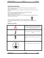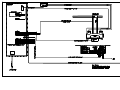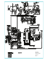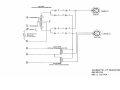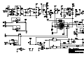
1
P/N 8000-HE425
Revision: D, November 18, 2005
HE425
HE425
X-Ray Generator
Installation, Operation &
Service Manual
HE425 X-Ray Generator
Revision D
Periodic Maintenance
Revision History
Revision
A
Date
03/15/2002
B
05/13/2002
C
D
10/28/2004
11/18/2005
Description
Initial release
Small spot MA station changes, schematic value update and part
number change.
Remove text page 29.
Upgraded to UL 60601 specifications and also upgraded schematics.
In the event of a malfunction that has contributed or could
contribute to a patient or operator injury, please contact:
In North America
Del Medical Imaging Corporation
50B North Gary Avenue
Roselle, IL 60172
Tel: (847) 288-7000
Fax: (847) 288-7011
© 2002 Universal
11/18/05
page ii
MANUAL IMPROVEMENT RECOMMENDATION
We at Del Medical Imaging Corporation are
most interested in improving the quality of
the Technical Documentation we provide.
Please identify improvements or corrections
and fax them to our Technical Publications
Department.
Name________________________________________________
Dealership____________________________________________
Manual Part Number____________________________________
Device Name__________________________________________
Recommendation or Correction__________________________________________________
_____________________________________________________________________________
_____________________________________________________________________________
_____________________________________________________________________________
_____________________________________________________________________________
_____________________________________________________________________________
_____________________________________________________________________________
_____________________________________________________________________________
_____________________________________________________________________________
Technical Support (847) 288-7000
Fax (847) 288-7011
e-mail: [email protected]
© 2002 Universal
11/18/05
page iii
TABLE OF CONTENTS
Revision History............................................................................................................................ ii
Applicable Standards ....................................................................................................................... 1
Abbreviations................................................................................................................................ 2
INTRODUCTION.............................................................................................................................. 2
Use of this Manual........................................................................................................................ 2
Safety ........................................................................................................................................... 2
Maximum Permissible Dose (MPD) ............................................................................................. 3
Manufacturer’s Responsibility ...................................................................................................... 3
Radiation Protection ..................................................................................................................... 4
Monitoring of Personnel ............................................................................................................... 4
OPERATION .................................................................................................................................... 7
Control Panel Controls & Functions ............................................................................................. 7
Operating Procedure .................................................................................................................... 8
PRE INSTALLATION ..................................................................................................................... 10
Space Requirements .................................................................................................................. 10
Specifications ............................................................................................................................. 10
Maximum Ratings....................................................................................................................... 10
Input Power Requirements Line Voltage.................................................................................... 10
Line Regulation .....................................................................................................................................11
Required Wire Size ...............................................................................................................................11
Circuit Protection (Mains) ........................................................................................................... 11
Accuracy Statements.................................................................................................................. 11
kVp........................................................................................................................................................11
mA.........................................................................................................................................................12
Time ......................................................................................................................................................12
Compatibility ...............................................................................................................................12
Bucky Compatibility .............................................................................................................................12
Aux. Power Output................................................................................................................................12
INSTALLATION.............................................................................................................................. 14
Test Equipment .......................................................................................................................... 14
Unpacking................................................................................................................................... 14
H.V. Transformer ........................................................................................................................ 15
Control ........................................................................................................................................ 15
Access to Inside of Control ...................................................................................................................15
H.V. Transformer Connections................................................................................................... 15
Collimator Power ........................................................................................................................ 15
Magnetic Lock Power ................................................................................................................. 16
Bucky Connections..................................................................................................................... 16
Incoming Line Cable Connection ............................................................................................... 17
Line Voltage Adjustments........................................................................................................... 17
Tube Selection............................................................................................................................ 19
CALIBRATION ...............................................................................................................................20
MA Calibration ............................................................................................................................ 21
Standby Filament Current Adjustment ..................................................................................................21
Initial mA Calibration ...........................................................................................................................21
Space Charge Calibration ......................................................................................................................22
kVp Calibration ........................................................................................................................... 23
50 mA Station (small focal spot)...........................................................................................................24
75 mA Station (small focal spot)...........................................................................................................24
100 mA Station (small focal spot).........................................................................................................25
200 mA Station (large focal spot)..........................................................................................................26
300 mA Station (large focal spot)..........................................................................................................26
400 mA Station (large focal spot)..........................................................................................................26
© 2002 Universal
11/18/05
page iv
THEORY OF OPERATION ............................................................................................................ 28
Turn ON sequence.................................................................................................................................28
KV Selection .........................................................................................................................................28
MA Selection.........................................................................................................................................28
Time Selection.......................................................................................................................................29
Calculation and Display of mAs............................................................................................................29
kVp Display...........................................................................................................................................29
Exposure Sequence................................................................................................................................30
Tube Protection .....................................................................................................................................31
SERVICE ADJUSTMENTS............................................................................................................ 32
SCHEMATICS................................................................................................................................ 33
DIAGNOSTICS .............................................................................................................................. 34
Troubleshooting SCR Block Gates........................................................................................................34
Troubleshooting Main SCR Gate Drive ................................................................................................34
Troubleshooting the Backup SCR Gate Drive.......................................................................................34
Renewal Parts................................................................................................................................ 36
PERIODIC MAINTENANCE .......................................................................................................... 37
Preventative Maintenance.......................................................................................................... 37
Cleaning Instruction:................................................................................................................... 37
Cleaning instruction ………………………………………………………………… ……… …….35
© 2002 Universal
11/18/05
page v
HE425 X-Ray Generator
Revision D
Introduction
Applicable Standards
This X-ray generator complies with the following regulatory and design standards:
FDA 21 CFR Subchapter J,
UL60601-1, CSA C22.2 No. 601.1, EN60601-1, IEC 60601-1, IEC 60601-1-2, and IEC
60601-2-7.
Degree of protection against harmful ingress of water: IPXO.Ordinary
Type of protection against electric shock: Class I
Mode of operation: 0.5% Duty Cycle.
Equipment not suitable for use in presence of a flammable anesthetic mixture with air or
with oxygen or nitrous oxide.
Degree of protection against electric shock is Type B applied part .
The function and intended application of this equipment is general radiography for
human use.
Definition of symbols
Warning symbol used to indicate a potential hazard to
operators, service personnel or to the equipment. It
indicates a requirement to refer to the accompanying
documentation for details.
This symbol states that there is accessible Dangerous
Voltage.
This symbol states that this product is categorized as
Type B.
This symbol identifies the Protective Earth Terminal
© 2002 Universal
11/18/05
page 1
HE425 X-Ray Generator
Revision D
Introduction
Abbreviations
mm
cm
Kg
Lbs
ºF
ºC
%
hPa
UL
CE
millimeter
centimeter
kilogram
pounds
degree Fahrenheit
degree Celsius
percent
Hecto Pascal
Underwriters Laboratories
Communautés Européennes
INTRODUCTION
Use of this Manual
Throughout the manual there are Note, Caution and Warning statements, which
contain information to assist the user of this manual. The information may direct
the user in the performance of a task or it may inform the user of a potentially
hazardous situation. Each alert word is always used with only one specific type of
information. The types of information contained in the statements are as follows:
NOTE: Information, which assists the user of the manual in the performance of a
task. It may provide the user with better methods of conducting the task, or it may
point out conditions which could cause the system to fail to operate properly.
CAUTION: Information, which alerts the user of the manual to situations that
could result in damage to the equipment.
WARNING: Information, which alerts the user of the manual to situations which
could be hazardous to the health of the patient, the operator, the maintenance
person or others.
Safety
It is vitally important that everyone associated with x-ray work is familiar with the
recommendations of the Department of Health, National Bureau of Standards,
and the National Council on Radiation Protection. The control of diagnostic
medical x-ray equipment varies in detail from state to state.
© 2002 Universal
11/18/05
page 2
HE425 X-Ray Generator
Revision D
Introduction
However, in general, all of the states adhere strictly to the established
recommendations of the NCRP. It is not practical to list all the relevant
recommendations in this manual. Therefore, prior to operation, be sure that all
personnel who are authorized to operate the x-ray system are familiar with the
established regulations of the authorities named above. Also, they should be
monitored to assure that they conform to the recommendations. Current sources
of information include:
•
National Council on Radiation Protection Report No. 33 (Medical X-ray
and Gamma-Ray Protection for Energies up to 1.0 MEV-Equipment
Design and Use. National Bureau of Standards Handbook no. 76
(Medical X-Ray Protection up to Three Million Volts). Refer to NCRP
Report No. 33.
• Current recommendations of the International Committee on Radiation
Protection.
Although x-ray radiation is hazardous, x-ray equipment does not pose any
danger when it is properly used. Be certain that all service and operating
personnel be properly informed on the hazards of radiation. Also, those
responsible for the system must understand the safety requirements for x-ray
operation. Study this manual and the manuals for each component in the system
to become aware of all the safety and operational requirements.
Maximum Permissible Dose (MPD)
Various studies of the effects of x-ray radiation have provided a foundation for
establishing the maximum permissible does (MPD) of x-ray radiation. The results
of these studies have been used by the NCRP and the ICEP to develop
recommendations for MPD.
ICRP recommends that the MPD to the most critical organs (heart, lungs, liver,
kidney, brain, etc.) accumulated at any age shall not exceed five rems multiplied
by the number of years beyond 18:
MPD = 5 X (N - 18) rems where N age in years
However, in no case shall the exposure exceed three (3) rems in any period of
13 consecutive weeks.
For hands, forearms, feet and ankles, the recommended MPD is 75 rems in any
one year.
Manufacturer’s Responsibility
Although this equipment incorporates protection against x-ray radiation other
than the useful beam, practical design cannot provide complete protection.
Equipment design does not compel the operator or his assistants to take
adequate precautions. Nor does it prevent the possibility of improper use which
© 2002 Universal
11/18/05
page 3
HE425 X-Ray Generator
Revision D
Introduction
may result in authorized or unauthorized persons carelessly, unwisely, or
unknowingly exposing themselves or others to direct or secondary radiation.
Allow only authorized, properly trained personnel to operate this equipment.
Be certain that all personnel authorized to use the equipment are aware of the
danger of excessive exposure to x-ray radiation.
This equipment is sold with the understanding that the manufacturer, its agents
and representatives, do not accept any responsibility for over exposure of
patients or personnel to x-ray radiation.
Furthermore, the manufacturer does not accept any responsibility for
overexposure of patients or personnel to x-ray radiation generated by this
equipment which is a result of poor operating techniques or procedures.
Also, no responsibility will be assumed for any machine that has not been
serviced and maintained in accordance with the system technical manual, or
which has been modified or tampered with in any way.
Radiation Protection
Because exposure to x-ray radiation may be damaging to health, use great care
to provide protection against exposure to the primary beam. Some of the effects
of x-ray radiation are cumulative and may extend over a period of months or
years. The best safety rule for x-ray operators is - Avoid exposure to the primary
beam at all times.
Any object in the path of the primary beam produces secondary (scattered)
radiation. The intensity of the secondary radiation is dependent upon the energy
and intensity of the primary beam and on the atomic number for the for the
objector material struck by the primary beam. Secondary radiation may be of
greater intensity than that of the radiation reaching the film. Take protective
measures to safeguard against it.
An effective protective measure is the use of lead shielding. To minimize
dangerous exposure, use such items as movable lead screens, lead impregnated
gloves and lead impregnated aprons. While servicing or operating x-ray
equipment, do not expose hands, wrists, arms or other parts of the body to the
primary beam.
Monitoring of Personnel
Monitoring of personnel to determine the amount of radiation to which they have
been exposed provides a valuable cross-check to determine whether or not
safety measures are adequate. It may reveal inadequate or improper radiation
protection practices and potentially serious radiation exposure situations.
© 2002 Universal
11/18/05
page 4
HE425 X-Ray Generator
Revision D
Introduction
The most effective method of determining whether or not the existing protective
measures are adequate is the use of instruments to measure the exposure in
RADS. This measurement should be taken at all locations where the operator, or
any portion of his body, may be during exposure. Exposure must never exceed
the accepted tolerable dose.
A common method of determining whether personnel have been exposed to
excessive radiation is the use of film badges. These are x-ray sensitive film
enclosed in a badge which incorporates metal filters of varying degrees of
transparency to x-ray radiation. Even though this device only measures the
radiation, which reaches the area of the body on which it is worn, it does furnish
an indication of the amount of radiation received.
© 2002 Universal
11/18/05
page 5
HE425 X-Ray Generator
Revision D
Introduction
Grounding Information
The figure below shows a typical interconnected x-ray system.
It is comprised of:
1. Tube Stand
2. Collimator
3. X-Ray Tube
4. Float-Top Table
5. Wall Stand
6. X-Ray Generator
7. Collimator Power Supply
All of these components are grounded to a common bus according to national
and local electrical codes. Also, all of the components should comply with UL
60601 Standards.
5
Buss Ground
1
3
2
4
6
7
© 2002 Universal
11/18/05
page 6
HE425 X-Ray Generator
Revision D
Operation
OPERATION
Control Panel Controls & Functions
10
11
6
5
4
1
7
2
3
8
9
1.
ON Button - Pushing this button will turn the unit ON.
2.
OFF Button - Pushing this button will turn the unit OFF.
3.
BUCKY Switch - Selecting Table or Wall will allow the respective optional
Bucky to energize when an exposure is initiated. Selecting Off will inhibit
either Bucky from energizing when an exposure is initiated.
4.
Minor kVp - This rotary switch selects kVp in 1-2 kVp increments and is
used in conjunction with the Major kVp switch to select the desired kVp.
5.
Major kVp - This rotary switch selects kVp in approximately 10 kVp
increments and is used in conjunction with the Minor kVp switch to select
the desired kVp.
6.
mA Selector - This rotary switch selects the desired mA level with the
corresponding small or large focal spot. S after the number indicates small
focal spot and L indicates large focal spot.
7.
Time Selector - This rotary switch selects the desired timer setting.
8.
PREP Button - Pushing and holding this button will initiate the Prepare
cycle. The anode in the x-ray tube begins to spin and the filament in the
© 2002 Universal
11/18/05
page 7
HE425 X-Ray Generator
Revision D
Operation
tube is elevated to the proper brightness for the mA selected. When the
Prepare cycle has successfully completed, in 1-2 seconds, the PREP
button will illuminate. Releasing the switch will terminate the Prepare
cycle. Note: If the PREP cycle does not begin when the button is pushed,
you may have previously encountered an error condition which is inhibiting
the PREP function. Turning the power off and on once will reset this
circuit, if an error has occurred.
9.
EXPOSE Button - Pushing and holding this button while the PREP button
is depressed and illuminated will initiate the exposure. The exposure
duration shall end either at the pre-selected time set by the Time selector
or when you release either the EXPOSE or PREP buttons; whichever
comes first. This button shall illuminate during the duration of the
exposure.
10.
mAs Digital Readout - Provides a pre-exposure indication of the mAs, as
calculated by multiplying the selected values for mA and Time. This
indicator is also used as an error message center if an improper technique
is selected. If a technique is selected that exceeds the power rating of the
x-ray tube, the indicator shall read '-E-' and the unit will not allow the Prep
cycle to be initiated. To clear the error, you need to reset the technique.
11.
kVp Digital Readout - Provides a pre-exposure indication of the kVp
selected. The display is self compensated for minor variations in the input
line voltage.
Operating Procedure
1
Push the ON button to energize the unit. If the unit does not turn on, verify
that the shut-off switch on the wall and the main circuit breaker is on. The
generator and x-ray tube should always be allowed to warm up for at least
twenty minutes prior to its planned use, to allow for proper temperature
stabilization, which will ensure accurate performance and prolong the life of
the tube.
2
Select the desired mA station. Ensure that mA is selected prior to adjusting
the kVp to its final value. Changing mA stations will affect the kVp indication.
3
Select the required time station and verify that the indicated mAs is equal to
the product that you desire. If not, readjust mA and Time accordingly.
4
Select the desired kVp.
5
Depress and hold the PREP button.
© 2002 Universal
11/18/05
page 8
HE425 X-Ray Generator
Revision D
Operation
6
When the PREP button illuminates, and you are ready to initiate an exposure;
depress and hold the EXPOSE button until you hear the audible beep and
see the light in the EXPOSE button extinguish.
7
If a mA overload condition is encountered during the exposure, an internal
detection circuit will immediately terminate the exposure and inhibit any
further exposures. The generator can be reset by pressing the power off
button and waiting for at least ten seconds before pressing the power on
button.
8
Release the PREP and EXPOSE buttons.
9
Push the OFF button to turn the unit off.
© 2002 Universal
11/18/05
page 9
HE425 X-Ray Generator
Revision D
Pre Installation
PRE INSTALLATION
Space Requirements
Specifications
Maximum Ratings
Maximum output:
Duty Cycle:
400 mA @ 100 kVp
300 mA @ 125 kVp
153 amps momentary on a 240 VAC
line. (100 kVp @ 400 mA.)
168 amps momentary on a 230 VAC
line. (100 kVp @ 400 mA.)
0.5%
Standby Current:
3 Amps.
Line current at max. rating (60Hz.):
Line current at max. rating (50 Hz.)
External Heat Generation: 2320BTU
Output P(w) = 0.707V(kvp) * I(mA)
Input Power Requirements Line Voltage
For Model HE425: Nominal 240 VAC, 194 - 277 VAC, 60 HZ, Single Phase
(specified at time of purchase)
For Model HE425/50HZ: Nominal 230 VAC, 194 - 277 VAC, 50 HZ, Single Phase
(specified at time of purchase)
Environment and Conditions for Transport/Storage
© 2002 Universal
11/18/05
page 10
HE425 X-Ray Generator
Revision D
Pre Installation
Transit/Storage Temperature: -40degC to +70degC
Operating Temperature: +10degC to +35degC.
Relative Humidity………….. 10-100%
Atmospheric pressure…….. 500hPa to1060hPa
Apparent Resistance of Supply Mains: 0.09 Ohm
Line Regulation
The 240 VAC power line, typically a 100-amp service, must have a regulation of
< 5% when operated at a momentary load of 140 amps.
Required Wire Size
The following Table lists the wire size for various distances from the power
disconnect near the control to the main distribution panel.
LINE VOLTAGE
240 VAC Single Phase
208 VAC Single Phase
WIRE SIZE FOR THE FOLLOWING DISTANCES:
0-50'
#2
#2
50'-100'
#00
#00
100'-200'
250 mcm
250 mcm
Circuit Protection (Mains)
National and local electrical codes require installation of a disconnecting switch
or circuit breaker, rated for at least 50% of the input current required for the
maximum momentary rating of the unit, which must be placed in a location
readily accessible from the x-ray control.
A common disconnect switch box is a 100 amp surface mounted safety
disconnect switch.
It is required that UL listed current limiting current 50A, 250V time delayed fuses
or double pole circuit breaker be provided for both lines of Generator power.
Accuracy Statements
The following statements assume kVp is measured with an invasive bleeder tank,
such as a Dynalyzer, with an oscilloscope to view the actual kv peaks; time is
measured with a similar device as kVp to allow the counting of the actual pulses;
and that mA is measured by an invasive average sensing mA meter placed in the
center leg of the high voltage secondary.
kVp
kVp Range: 40 to 125 kVp
Resolution: 1 to 2 kV in steps
Accuracy:
+/- 10% of indicated value
© 2002 Universal
11/18/05
page 11
HE425 X-Ray Generator
Revision D
Pre Installation
mA
Selections:
Accuracy:
Small Spot: 50, 75, 100 mA
Large Spot: 200, 300, 400 mA
+/- 15%
Time
Selections:
Accuracy:
23 selections, between 1/120 second to 6 Seconds
+/- 1/120th second through 1/2 second and +/- 1/60 second above
1/2 second
Compatibility
This 402.100.00 control is only compatible with the 402.501.00 high voltage
generator.
This unit is compatible with the following x-ray tubes:
Toshiba E7239 (1X2mm)
Toshiba E7242 (0.6X1.5mm)
Varian RAD 8 (1X2mm)
Varian RAD 13 (1X2mm)
Bucky Compatibility
Maximum Number of Buckys:
Control Type:
2
120 VAC
Aux. Power Output
Locks:
Collimator:
24 VDC, fused at 2 Amps
24 VAC, fused at 8 Amps
© 2002 Universal
11/18/05
page 12
HE425 X-Ray Generator
© 2002 Universal
Revision D
11/18/05
Installation
page 13
HE425 X-Ray Generator
Revision D
Calibration
INSTALLATION
Warning: The instructions in this manual are intended for qualified personnel
only.
Test Equipment
•
Digital VOM
•
Dynalyzer with trigger level set at 90% or HV voltage divider tank
•
Storage Oscilloscope
•
mAs Meter
Preliminary Site Inspection
Before beginning installation, inspect the x-ray room to verify compliance with
specifications for the following:
•
•
•
Incoming Line
Mains Switch
Space Requirements
Unpacking
Upon receipt of the equipment, inspect all shipping containers for signs of
damage. If damage is found, notify the carrier or his agent immediately.
When the equipment is unpacked; inspect all pieces for visible damage. If any
damaged parts are detected, repair or order replacements without delay to
prevent unnecessary delay in installation.
Before beginning the installation, verify the following:
•
•
•
•
All hardware is secure
All internal wiring is secure
Configuration is correct
All items on the customer order are included in the system.
© 2002 Universal
11/18/05
page 14
HE425 X-Ray Generator
Revision D
Calibration
H.V. Transformer
Locate the HV transformer in its final location. Open the inspection port and
ensure that the dielectric oil level of the unit is approximately 1/2" from the top of
the unit. If necessary, add Shell Diala-AX oil as required. (Shell Diala-AX does
not contain any PCB’s)
Control
Locate the control close to its final location leaving some room behind it to
facilitate installing necessary cabling.
Access to Inside of Control
Remove the two screws at the bottom of the front access panel and pull the
bottom forward.
To gain access to the top portion of the control, remove the two screw/alignment
pin assemblies at the sides of the chassis that hold the top portion of the access
panel in place. Swing the upper portion of the control upwards.
H.V. Transformer Connections
The two control-transformer cables for the H.V. primary and the auxiliary
transformer, are pre-wired to the control at the factory.
Connect the cables to the H.V. transformer according to the respective markings
of each wire.
Caution: The terminal pins on the high voltage connectors are extremely
delicate and can easily be damaged. Ensure that they are straight and that the
split ends of the pins are slightly open. Use a thin metal blade to open them
slightly, if necessary.
Clean the HV terminals carefully, using a clean, lint-free cloth and a light solvent,
such as alcohol, before applying the vapor-proofing compound.
Use a clean non-conducting applicator to coat each cable plug with vaporproofing compound. Apply a one half inch high cone of the compound to the end
of each insulator before inserting it into the high voltage socket. You may also
apply a small amount of the compound to the threads of the connector socket of
the strain relief flange, to facilitate easier threading of the hardware.
Collimator Power
For 24 VAC collimator power connect the collimator power cable to TS3-1 and
TS3-3.
© 2002 Universal
11/18/05
page 15
HE425 X-Ray Generator
Revision D
Calibration
Magnetic Lock Power
For 24 VDC lock power connect lock supply cable to TS3-5 and TS3-7.
Bucky Connections
The control is shipped with a jumper in place to allow operation without a Bucky.
If a Bucky is to be used, remove the jumper between TS3-18 and TS3-19 and
connect the Bucky as follows:
BUCKY CONNECTIONS
HE425 Control
Function
Bucky Exp
Contacts
(24 VAC)
Bucky Exp
Contacts
(24 VAC)
Bucky
Drive
(115 VAC)
Bucky
Drive
Return
(115 VAC)
Bucky
Home
(115 VAC)
© 2002 Universal
Table
Wall
Midwest
Bucky
Progeny/
Liebel
Bucky
Liebel Bucky
(older models)
TS3-19
TB1
TS3-20
WB1
B1
1
B1
TS3-17
TB2
TS3-18
WB2
B2
2
B2
TS3-15
TB3
TS3-16
WB3
B3
3
B3
TS3-13
TB3
TS3-14
WB4
B4
N
B4
TS3-10
TB8
TS3-11
WB8
B8
L
B8
11/18/05
page 16
HE425 X-Ray Generator
Revision D
Calibration
Incoming Line Cable Connection
WARNING: Ensure that the main power safety disconnect is OFF prior to
connecting or disconnecting the line cable.
Measure the incoming line voltage at the disconnect switch (wall panel) before
connecting the power cable (part # 3480-0141) that will go to the console.
Connect the wires from the incoming line cable marked L1 and L2 to terminals 1
and 2 of TS5. Connect the GROUND lead from the same cable to the CHASSIS
GROUND lug, located on the bottom panel of the control console, near TS5.
Line Voltage Adjustments
Terminals on TS1 and TS2 are provided for coarse and fine adjustments of the
incoming line voltage. Measure the line voltage at the disconnect switch and
relocate wires marked "ALVF" and “ALVC”, according to the following chart:
Line
Voltage
194
198
202
207
211
214
218
221
223
227
230
234
238
241
243
247
250
277
Refer to schematic 120-5022
configuration of the autoformer.
© 2002 Universal
ALVC
ALVF
TS1-5
TS1-5
TS1-5
TS1-4
TS1-4
TS1-4
TS1-4
TS1-4
TS1-3
TS1-3
TS1-3
TS1-3
TS1-3
TS1-3
TS1-2
TS1-2
TS1-2
TS1-1
TS2-6
TS2-7
TS2-8
TS2-4
TS2-5
TS2-6
TS2-7
TS2-8
TS2-3
TS2-4
TS2-5
TS2-6
TS2-7
TS2-8
TS2-3
TS2-4
TS2-5
TS2-7
for
additional
11/18/05
details
regarding
voltage
page 17
HE425 X-Ray Generator
Revision D
Calibration
Ensure that the incoming line voltage adjustment for the autotransformer is
correct and that all connections are tightly secured before connecting the
incoming line cable to the safety disconnect switch on the wall.
All of the components used with the generator (X-ray tube, collimator, genrator,
etc.) must comply with UL 60601 Standards.
© 2002 Universal
11/18/05
page 18
HE425 X-Ray Generator
Revision D
Calibration
Tube Selection
The HE425 generator is compatible with 4 different x-ray tubes. To ensure that
the proper tube protection profile for your tube has been selected, refer to the
chart below and install jumpers in JP1 on the main control board, as indicated:
X- RAY TUBE
Toshiba E7239 (1 X 2 mm)
Toshiba E7242 (0.6 X 1.5 mm)
Varian RAD 13 (1 X 2 mm)
Varian RAD 8 (1 X 2 mm)
Position
0
installed
Position
1
Position 2
installed
Installed
Installed
Verify that jumper (J8) on rotor control board are set for the type of X-ray tube
you are using according to Table and Figure on below.
X- Ray Housing Type
Varian RAD 8 (1 X 2 mm)
Varian RAD 13 (1 X 2 mm)
Toshiba E7239 (1 X 2 mm)
Toshiba E7242 (0.6 X 1.5 mm)
Position of jumper J8
Middle and lower (2 in Figure below)
Middle and lower (2 in Figure below)
Upper and middle (1 in Figure below)
Upper and middle (1 in Figure below)
2
1
© 2002 Universal
11/18/05
page 19
HE425 X-Ray Generator
Revision D
Calibration
Rotor Cable Connections
The wires of the rotor cable are labeled T5, T6, MAIN, PHASE & COM. Connect them as shown below.
MAIN PHASE COM
T5
T6
CALIBRATION
To ensure accuracy, always allow the generator to warm up for at least
twenty minutes prior to performing these calibration procedures. If the unit
is turned off and allowed to cool at any point in the process of calibration,
it must be warmed up again before proceeding.
WARNING: Exercise extreme caution with regard to the temperature of the x-ray
tube during the calibration procedures. You must allow sufficient time for the
anode of the tube to cool between exposures, in order to prevent permanent
damage to the x-ray tube.
Refer to the cooling charts for the anode and tube housing in the documentation
that accompanied your x-ray tube.
The installer should read and understand the information provided with the x-ray
tube prior to making any x-ray exposures.
© 2002 Universal
11/18/05
page 20
HE425 X-Ray Generator
Revision D
Calibration
It is recommended that the measuring equipment connected to the x-ray system
should be used to monitor mA and kVp throughout the entire calibration
procedure to reduce the chances of misleading test results.
mA Calibration
Connect a Dynalyzer or a mA meter to perform the following procedure.
If no Dynalyzer is available, mA may also be measured by removing the jumper
between the “MA-" and "MA+” terminals 5 and 6 of TS4, and connecting a DC
mA meter between those terminals.
Caution: Be sure to replace this jumper after removing the mA meter, when
calibration has been completed.
Standby Filament Current Adjustment
Measure the filament secondary current during standby with a Dynalyzer and
verify that the filament secondary current is in the range of 3.0 - 3.2 amps RMS.
If required, adjust the slider band on resistor RB.
If no Dynalyzer is available, the field engineer may adjust the filament by eye,
adjusting resistor RB so that a dull glow just begins to show on the selected
filament.
Initial mA Calibration
You must first set the kV Major and Minor switches in a position that produces no
voltage across the space charge transformer. This will allow the engineer to
calibrate the base value all of the individual mA settings, with no additional effect
from the space charge compensation voltage.
At this time, the value of the indicated kVp is not important.
•
•
•
Set the kVp Major and Minor switches fully counter clockwise.
Rotate the kVp Major switch six audible clicks clockwise.
You may now calibrate each of the mA stations for its indicated value (50,
75, 100, 200, 300, and 400 mA) at this kVp setting, by adjusting the
respective bands on resistors RXL and RLS. The leads connected to the
© 2002 Universal
11/18/05
page 21
HE425 X-Ray Generator
•
•
•
Revision D
Calibration
bands of these resistors are marked with numbers which correspond to
the mA stations. Moving any one of these bands to the right increases the
mA for the corresponding mA station.
Select a time setting of 0.1 second. If you are using an mA meter, select
a longer time, such as 1 second, to allow the meter reading to
stabilize properly.
Make a series of exposures at each of the available mA stations and
adjust resistor RXL or RXS as necessary to obtain the desired mA.
When all of the mA stations have been calibrated for their proper base
value, you may continue with the space charge calibration procedure.
Space Charge Calibration
Space charge compensation for all mA stations is adjusted with resistor RSC.
The leads connected to the bands of RSC are also marked with numbers which
correspond to the same mA stations. Moving any one of these bands to the right
causes a decrease of mA at high kVp levels and an increase of mA at low kVp
levels for the corresponding mA station. This is commonly referred to as space
charge compensation.
Normal tracking of mA over the entire range of kVp will result in mA values
slightly higher than selected near 80 kVp and mA values slightly lower than
selected levels at the high and low ends of the kVp range (125 and 50). See
chart below:
1. Select the 50 mA station, 80 kVp, and 0.1 second.
2. Select 50 kVp and note the mA produced.
© 2002 Universal
11/18/05
page 22
HE425 X-Ray Generator
Revision D
Calibration
3. Select 120 kVp and note the mA produced.
4. If the mA produced at 120 kVp is higher than the mA produced at
50kVp, move the respective band of RSC to the right. If lower,
move the band to the left.
5. Repeat steps (1) through (4) until no further adjustments are
necessary.
6. Check mA tracking from 50 to 120 kVp and fine tune as required.
The unit must track within ± 10 % of the selected mA value.
7. Repeat steps (1) through (6) for the remaining mA stations.
kVp Calibration
The control has an adjustable kVp Meter Compensation Circuit that adjusts the
displayed value of the kVp meter to compensate for the loading effects of
different mA selections. This circuit consists of two separate 'offset' and "slope"
potentiometer adjustments for each mA station, for a total of twelve pots on the
board.
These adjustment pots are located on the KV Adjust PCB, which is mounted
above the Main Control PCB in the top section of the control, beneath the control
panel lid.
The first group of potentiometers on the left side of the board are the 'Offset'
adjustments and the second group of potentiometers on the right side are the
'Slope' adjustments. The pots are labeled MA1 thru MA6 on both sides of the
board, which correspond to 50 mA, 75 mA, 100 mA, 200 mA, 300mA and 400
mA, respectively.
The "Offset' adjustment raises or lowers the reading of the kVp meter the same
amount at all points of the kVp range for the selected mA station. See illustration
below:
The 'Slope' adjustment changes the reading of the kVp meter a greater amount
at the higher kVp settings than at the lower kVp settings for the same respective
mA station. See illustration below:
© 2002 Universal
11/18/05
page 23
HE425 X-Ray Generator
Revision D
OFFSET
KV
DISPLAY
Calibration
SLOPE
KV
DISPLAY
PRIMARY VOLTS N.L.
PRIMARY VOLTS N.L.
NOTE: In order to accurately compare the actual measured kVp of an exposure
to the indicated kVp on the display, the tube current must first be accurately
calibrated. Failure to do so will result in inaccurate kVp.
50 mA Station (small focal spot)
1) Select 50 mA and 50 kVp. While monitoring the mA and kVp outputs,
compare the measured kVp to the kVp meter's pre-exposure indication.
2) Adjust the 50 mA KV Offset pot, MA1, until the kVp meter's pre-read
indication matches the measured kVp output.
3) Select 120 kVp. Make an x-ray exposure and adjust the KV Slope pot
"MA1" until the kVp meter's pre-exposure indication matches the
measured kVp output. Repeat steps 1, 2, and 3 until no further
adjustments are necessary.
4) Check final kVp meter tracking over the entire kVp range. Under normal
conditions the kVp meter's indication will not deviate from the measured
kVp output by more than 5 kVp.
75 mA Station (small focal spot)
1) Select 75 mA and 50 kVp. While monitoring the mA and kVp outputs,
compare the measured kVp to the kVp meter's pre-exposure indication.
2) Adjust the 75 mA KV Offset pot, MA2, until the kVp meter's pre-read
indication matches the measured kVp output.
3) Select 120 kVp. Make an x-ray exposure and adjust the KV Slope pot
"MA2" until the kVp meter's pre-exposure indication matches the
measured kVp output. Repeat steps 1, 2, and 3 until no further
adjustments are necessary.
© 2002 Universal
11/18/05
page 24
HE425 X-Ray Generator
Revision D
Calibration
4) Check final kVp meter tracking over the entire kVp range. Under normal
conditions the kVp meter's indication will not deviate from the measured
kVp output by more than 5 kVp.
100 mA Station (small focal spot)
1) Select 100 mA and 50 kVp. While monitoring mA and kVp output,
compare the measured kVp to the kVp meter's pre-exposure indication.
2) Adjust the 100 mA KV Offset pot, MA3, until the kVp meter's pre-read
indication matches the measured kVp output.
3) Select 120 kVp. Make an x-ray exposure and adjust the KV Slope pot
"MA3" until the kVp meter's pre-exposure indication matches the
measured kVp output. Repeat steps 1, 2, and 3 until no further
adjustments are necessary.
4) Check final kVp meter tracking over the entire kVp range. Under normal
conditions the kVp meter's indication will not deviate from the measured
kVp output by more than 5 kVp.
© 2002 Universal
11/18/05
page 25
HE425 X-Ray Generator
Revision D
Calibration
200 mA Station (large focal spot)
1) Select 200 mA and 50 kVp. While monitoring the mA and kVp outputs,
compare the measured kVp to the kVp meter's pre-exposure indication.
2) Adjust the 200 mA KV Offset pot, MA4, until the kVp meter's pre-read
indication matches the measured kVp output.
3) Select 120 kVp. Make an x-ray exposure and adjust the KV Slope pot
"MA4" until the kVp meter's pre-exposure indication matches the
measured kVp output. Repeat steps 1, 2, and 3 until no further
adjustments are necessary.
4) Check final kVp meter tracking over the entire kVp range. Under normal
conditions the kVp meter's indication will not deviate from the measured
kVp output by more than 5 kVp.
300 mA Station (large focal spot)
1) Select 300 mA and 50 kVp. While monitoring the mA and kVp outputs,
compare the measured kVp to the kVp meter's pre-exposure indication.
2) Adjust the 300 mA KV Offset pot, MA5, until the kVp meter's pre-read
indication matches the measured kVp output.
3) Select 120 kVp. Make an x-ray exposure and adjust the KV Slope pot
"MA5" until the kVp meter's pre-exposure indication matches the
measured kVp output. Repeat steps 1, 2, and 3 until no further
adjustments are necessary.
4) Check final kVp meter tracking over the entire kVp range. Under normal
conditions the kVp meter's indication will not deviate from the measured
kVp output by more than 5 kVp.
400 mA Station (large focal spot)
1. Select 400 mA and 50 kVp. While monitoring the mA and kVp outputs,
compare the measured kVp to the kVp meter's pre-exposure indication.
2. Adjust the 400 mA KV Offset pot, MA6, until the kVp meter's pre-read
indication matches the measured kVp output.
3. Select 100 kVp. Make an x-ray exposure and adjust the KV Slope pot
"MA6" until the kVp meter's pre-exposure indication matches the
© 2002 Universal
11/18/05
page 26
HE425 X-Ray Generator
Revision D
Calibration
measured kVp output. Repeat steps 1, 2, and 3 until no further
adjustments are necessary.
4. Check final kVp meter tracking over the entire kVp range. Under normal
conditions the kVp meter's indication will not deviate from the measured
kVp output by more than 5 kVp.
© 2002 Universal
11/18/05
page 27
HE425 X-Ray Generator
Revision D
Theory of Operation
THEORY OF OPERATION
Turn ON sequence
The incoming line voltage is passed through K1, the main line contactor, to the
inputs of the main autotransformer that have been selected according to the
measured line voltage.
Pressing the ON switch on the operator’s control activates the line contactor. The
L3/T3 terminal of the line contactor is used to latch the incoming line voltage to
the coil of the contactor, through the Normally Closed contacts of the OFF switch.
Pressing the OFF switch interrupts the voltage, opening the latching contact and
deactivating the contactor.
When the line contactor is closed the incoming line voltage is applied to the
autotransformer, which then presents voltages at all of its output taps.
120 VAC, fused at 8 Amps, through fuse F2, is then applied to the Main control
board power supply transformer (T2), through fuse F1 and connector H12. The
output from T2 is rectified and supplied to linear regulators, which produce + 12
VDC, +5 VDC, and -5 VDC, which is used to operate the main control board
circuitry, as well as the 7 segment displays for kVp and mAs.
Fuse F2 is also used to supply 117 VAC for all auxiliary components, such as the
Buckys, the Stator Drive PCB Power Supply. The Stator Drive PCB has onboard primary transformer fusing for its power supply, as well as a 10 Amp fuse
for the rotor boost voltage.
kV Selection
Tapped voltages from the autotransformer are selected by the kVp Major and
minor switches and connected to the two SCR blocks. This voltage is also routed
to the space charge transformer (T3). The outputs from KV Minor tape switch is
sent to the main control board, where it is scaled and rectified and used to
provide the raw drive for the kVp display, after being processed through the kV
adjust board and the main control board.
mA Selection
A three-deck six position switch on the operator’s console is used to manually
select the tapped voltages from the space charge resistor and resistors RXL and
RXS, to provide voltage for the primary of the filament drive transformers in the
high tension tank. The third deck of this switch is used to provide selection data
to the main control board, through connector H11. This data is used to select
© 2002 Universal
11/18/05
page 28
HE425 X-Ray Generator
Revision D
Theory of Operation
offset and slope compensation from pots on the kV Adjust Board and as
addressing information for mAs calculations.
Time Selection
23 available time stations may be selected using the Time Selector switch on the
front panel of the operator’s control. The output from this switch is a five bit
binary encoded word, which is used to provide addressing information to U27, to
decode the actual exposure time, and to U25, to be used for mAs calculations.
Calculation and Display of mAs
Address data from the time selection and mA switches is used by U25 to lookup
values of mAs, which are then output to a group of selectable latches (U23-A,B
and U29-A), which feed into a common bus to a seven segment display driver
(U22). Each of these latches holds one of the three digits that will be sent to the
mAs display, and they are enabled sequentially, in time with the selection of the
individual numbers on the front panel of the display.
kVp Display
The voltage that has been selected using the kV Major and Minor switches, is
fused in the lower portion of the cabinet and then sent to the main control board,
at connector H2.
Caution:
This sample voltage may range between 80 to 300 VAC, depending upon the
value of kVp that has been selected. Although this voltage has been fused for
safety, the field service engineer should be aware of the potential hazards for
shock and component damage. Use appropriate care when inspecting this
portion of the board while the unit is energized.
This voltage is stepped down at T3, and then it is scaled and rectified at U2,
before being sent to the KV Adjust board, where it is compensated for the
selected mA, using selected potentiometers to attenuate the signal and provide
the desired amount of DC offset to compensate for voltage drop under load.
The compensated kV signal is then fed to a voltage to frequency converter (U4),
which converts the analog voltage to a pulse train, which varies between
approximately 3 to 5 KHz, depending on the selected kV. This pulse train is fed
to U14, which is clocked at 6 Hz by U9. This clocking action reads out the stored
© 2002 Universal
11/18/05
page 29
HE425 X-Ray Generator
Revision D
Theory of Operation
value of the register inside U14 and then resets it. In this manner, the voltage is
converted into proportionate pulses, which are counted and displayed again as
voltage (kVp).
This metering system is self-compensating for variations in the incoming line,
which eliminates the need for manual line compensation.
Exposure Sequence
The exposure sequence begins by depressing the PREP switch on the operator’s
console. This provides 120 VAC to the stator drive PCB, which closes the K3
relay, switching the primary filament voltage from standby to the boost level, as
selected by the mA switch, and providing power to the space charge transformer.
At the same time, relay K1 on the stator drive PCB is also activated, which
provides the 240 VAC boost voltage to the stator of the x-ray tube. At the end of
a 1.2 to 1.5 second delay, which is timed on the stator drive PCB, relay K4
closes, lighting the ready light behind the PREP switch and enabling the 24 VDC
voltage that will be used to initiate the actual exposure on the main control board
(connector H4). At this time, relay K1 opens and K2 closes, removing the 240
VAC boost from the stator and applying the 50 VAC run voltage.
When no Buckys are selected, the 24 VDC signal is routed through the exposure
switch to connector H4 through the normally closed contacts of the Bucky Enable
relay (K5). If either Bucky has been selected, this voltage activates the Bucky
drive relay, which energizes the appropriate Bucky, and the 24 VDC signal is
then sent through the B1 and B2 contact closures of that Bucky to connector H4.
On the main control board, the 24 VDC signal activates opto coupler OC2, which
sends a signal through several gates of U32, setting the exposure latch of U21 to
the active state, and passing the exposure release signal along through U7-B.
This signal activates command to freeze the kVp display during the exposure, as
well as enabling the 120 Hz pulse train at U8-A, which is divided to 60 Hz at U8A and used to clock U28, a binary counter that feeds its outputs to a set of binary
comparators (U24, 26, and 30) which compare the desired time against the
elapsed time of the exposure and terminate the exposure by resetting the
exposure latch. The same pulse train from U8-A also provides pulses through a
network of transistors (Q1, 2, 3), which provide pulses to the gates of the main
SCR block.
The exposure release signal also activates the audible alert and the BU SCR
gate drive relay (K1-B), which arms the BU SCR for the exposure.
When counter U28 reaches the desired number of counts, the binary
comparators are satisfied, and a signal is released to terminate the exposure, by
resetting the exposure latch. The generator is capable of beginning another
© 2002 Universal
11/18/05
page 30
HE425 X-Ray Generator
Revision D
Theory of Operation
exposure by releasing and pressing the exposure switch again, after an exposure
has timed out properly, as long as the PREP switch has not been released.
Additionally, there is a voltage detection circuit (opto coupler OC1) on the main
control board, which senses the presence of line voltage across the BU SCR,
which would indicate a failure of the main SCR. This circuit will produce a signal
which can also hold the reset of the exposure latch, disabling the initiation of any
exposures and lighting LED 4, the SCR FAIL LED.
Tube Protection
EPROM U25 is also used to implement the tube protection profile of the selected
x-ray tube, by looking up the profile from a series of addressable lookup tables in
its memory. Address information for time, mAs, and kVp are fed into this
EPROM, along with address information from the jumpers at JP1, which are used
to identify the tube type in use.
If the selected technique is beyond the range of the tube protection profile, the
LIMIT bit from pin 3 of U25 will be activated, which will inhibit any exposures until
a proper technique has been selected. Additionally, this EPROM will generate
the error message “-E-“, which will be displayed in the mAs display until the
technique is within the appropriate limits for the tube.
© 2002 Universal
11/18/05
page 31
HE425 X-Ray Generator
Revision D
Service Adjustments
SERVICE ADJUSTMENTS
The field service engineer is responsible for the preventative maintenance of the
unit. Under normal circumstances, these procedures will have already been
covered in the Calibration and Periodic Maintenance chapters of this manual.
Additional information for the theory of operation and troubleshooting of this
generator may be found in the Theory and Diagnostics chapters of this manual.
Information related to the identification of replacement parts for this generator
may be found in the Renewal Parts chapter of this manual.
© 2002 Universal
11/18/05
page 32
HE425 X-Ray Generator
Revision D
Schematics
SCHEMATICS
Drawing number
Description
034-5076
Interconnect diagrams for HE425
generator and various Tube/Wallstands
Overall Control Wiring Diagram
Schematic, Main Control PCB
Schematic – KV Adjust PCB
Schematic, HT Transformer Assy. 3560
Schematic, Rotor Control PCB
120-5022
124-5090
482.101.06S
482.501.01S
124-5076S
# Sheets Current Rev.
2
1
2
1
1
1
See Config.
table below
1
1
2
2
2
Configuration – Schematic Match Table
Tubestand
Model
Collimator
Model
Wallstand/
Table Model
Refer to
Drawing #
FMTS Tubestand
K860 Floor-Ceiling
Mounted Tubestand
MC Series
MC Series
RT100/3546E
3546E
034-5076S7
034-5076S11
© 2002 Universal
11/18/05
Current
Rev.
2
1
page 33
13
14
15
12
1
5
2
4
X0
X1
X2
X3
X4
X5
X6
X7
8
R91
VCC
A
B
C
OUT
EN
VEE
16
11
10
9
3
6
7
74HC4051
392K
T3
SEE NOTE 1
13
14
15
12
1
5
2
4
R92
392K
X0
X1
X2
X3
X4
X5
X6
X7
8
16
VCC
A
B
C
OUT
EN
VEE
11
10
9
3
6
7
VCC
RB7
RB6
Vpp
VCC
VCC
VCC
C100
GND
R100
10k
012
04
05
06
07
00
01
02
03
MCLR/Vpp
RA0/AN0
RA1/AN1
RA2/AN2
RA3/AN3
RA4
RA5/AN4
RE0
RE1
RE2
OSC1/RA7
OSC2/RA6
RC0
RC1
RC2
RC3/SCK
RD0/PSP0
RD1/PSP1
ZTX792A
H100
.1uF
RB7/PGD
RB6/PGC
RB5/AN13/CCP3
RB4/AN11
RB3/AN9
RB2/AN8
RB1/AN10
RB0/INT/AN12
RD7/PSP7
RD6/PSP6
RD5/PSP5
RD4/PSP4
RC7/RX/DT
RC6/TX/CK
RC5/SDO
RC4/SDI/SDA
RD3/PSP3
RD2/PSP2
R103
ZTX792A
1K
VCC
R104
ZTX792A
1K
Q102
R101
1K
MMSD
LED100
MNSD
MLSD
U101
1
2
3
4
5
6
7
8
9
PIC16F777
H8
Q101
40
39
38
37
36
35
34
33
30
29
28
27
26
25
24
23
22
21
VSS
08
09
010
011
1
2
3
4
5
6
7
8
9
10
13
14
15
16
17
18
19
20
1K
Q100
VDD
VDD
U100
32
R102
IN1
IN2
IN3
IN4
IN5
IN6
IN7
IN8
RN100
18
17
16
15
14
13
12
11
OUT1
OUT2
OUT3
OUT4
OUT5
OUT6
OUT7
OUT8
10
COM
9
10
11
12
13
14
15
16
8
7
6
5
4
3
2
1
MDP
MG
MF
ME
MD
MC
MB
MA
147
31
4
11
2
P1, P2 VOLTS TO H2-2 & H2-4
VSS
3
12
1
C61 0.1uF
C60 0.1uF
C59 0.1uF
ULN2803
H101
R105
100
NOTES;
124-5088: R13 VALUE = 4.75K
124-5091: R13 VALUE = 6.19K
TX-D
RX-D
COM-D
DEL MEDICAL
SCHEMATIC, MAIN CONTROL BOARD
124-5090S, SHT. 1 OF 2
REV. 1 7/10/08
1
2
3
4
5
6
7
8
9
10
11
12
13
14
15
16
VCC
VCC
VCC
VCC
7
C62
VCC
VCC
VCC
2
1
K1:B
VCC
14
VCC
14
7
7
H16
K1:A
C58
VCC
VCC
VCC
VCC
VCC
VCC
VCC
VCC
U13A
2
U13D
8
8
U12C
U13B
1
3
9
13
4
U13F
9
10
11
12
DEL MEDICAL
SCHEMATIC, MAIN CONTROL BOARD
124-5090S, SHT. 2 OF 2
REV. 1 7/10/08
HE425 X-Ray Generator
Revision D
Diagnostics
DIAGNOSTICS
Warning:
Turn power OFF at main disconnect switch (wall breaker) before
performing any of these procedures, unless otherwise instructed. Pay
close attention to the written sequence of operations for any of these
tests.
Troubleshooting SCR Block Gates
•
•
•
Turn power OFF.
Unplug header H7 and H3 (on Main Control Board) for Backup and main
SCR blocks.
Measure between pins 1 and 2 and then pins 2 to 3 of each header. All
readings should be approximately 15 Ohms. Higher or lower readings may
indicate a problem with the SCR block.
Troubleshooting Main SCR Gate Drive
•
•
•
•
•
•
Turn power OFF.
Unplug both SCR gates from headers H3 and H7 on Main Control Board.
Connect an oscilloscope or DC voltmeter from the right end of resistor
R31 or R34 to one of the GND pins on Header H13 (pin 4, 5, or 6). Expect
to measure a voltage near +12 VDC.
Turn power ON.
Before an exposure is made, the meter should read either zero volts or 12
Volts DC (high or low state). During an exposure the output will be a 12
Volt, 60 Hz square wave, which the DC voltmeter should read as
approximately 6 VDC.
Make an exposure and verify the output of the square wave gate drive
signal. At the end of an exposure the drive signal may stop in either the
high or low state. This is normal operation.
Troubleshooting the Backup SCR Gate Drive
•
•
•
•
•
Turn power OFF. Unplug connector H7 from the Main Control Board.
Turn power ON.
Connect an Ohmmeter between pins 1 and 3 on header H7 on the Main
Control Board.
In standby, the Ohmmeter should indicate an open circuit.
Make an exposure. The Ohmmeter should now measure approximately 15
Ohms, if relay K1 is operating properly.
© 2002 Universal
11/18/05
page 34
HE425 X-Ray Generator
•
•
Revision D
Diagnostics
Turn power OFF.
Check diodes D11 and D12 with the Ohmmeter. Shorted or open diodes
must be replaced.
If an SCR is suspected as being bad, then order a replacement.
© 2002 Universal
11/18/05
page 35
HE425 X-Ray Generator
Revision D
Renewal Parts
Renewal Parts
Description
Main Control Board, 60HZ
Operating Firmware, 60 Hz
Operating Firmware, 50 Hz
KV Adjust Board
Stator Drive Board
CV Transformer – 60 Hz
Cap for 60 Hz CV Transformer, 2 MFD
50 Hz CV Transformer and Capacitor
MA Selection Switch, 23 position
Time Selection Switch
kVp Major or Minor Selector Switch
Seven segment display assy. for kVp or mAs
PREP or EXPOSE Switch
Bucky Selection Switch
Power ON or OFF Switch
Knob for kVp Major or Minor switch (no pointer)
Knob for Time or mA selector switch (with pointer)
Cable assy. for kVp display
Cable assy. for mAs display
Cable assy. from main control board to kV adjust board
Transformer, Filament or Large Filament boost , T3, T4
Line contactor, 3PDT, 30A.
SCR Block, SCR 1 or SCR2
Capacitor, 20 – 30 MFD, 300 V for stator
Adjustable resistor, 50 Ohms, 175 W, RXL
Adjustable resistor, 100 Ohms, 175 W, RXS
Adjustable resistor, 25 Ohms, 175 W, RSC
Adjustable resistor, 150 Ohms, RB
Relay, 12 VDC, MA Overload Sense,
Relay, 120 VAC, MA overload Lockout
Relay, 120 VAC, Bucky enable, K5
Relay, 24 VDC, Bucky drive, K6
Relay, 24 VAC, Prep., K7
Bridger Rectifier, BR1 or BR2
Cap, Switch, ON or OFF, Black
Cap, Switch lens, PREP, Green
Cap, Switch Lens, Expose, Red
Cable Assy., Time Select Switch
Cable Assy., MA Switch
Assy., Autotransformer
HT Transformer Assy.
© 2002 Universal
11/18/05
Part Number
124-5088
622-5079G1
622-5080G1
470.100.02
124-5076
465.101.02
3407-0205
5602-0094
161.101.00
470.100.05
3481-0405
470.300.00
161.100.01
161.100.06
161.100.00
632-5028
133.101.02
126-5167G1
126-5168G1
163.101.00
165.101.00
161.100.08
173.101.01
3481-0417
3481-0195
3481-0197
3481-0194
469.101.03
645-5017
645-5018
645-5018
645-5019
645-5016
173.101.00
161.100.02
161.100.04
161.100.05
126-5169G1
126-5270G1
636-5026
402.501.01
page 36
HE425 X-Ray Generator
Revision D
Periodic Maintenance
PERIODIC MAINTENANCE
Preventative Maintenance
Preventive maintenance inspections should be performed on a semi-annual
basis and should include the following:
•
Inspect all electrical wires and cables for abrasions, cuts or cracks.
•
Inspect all control buttons and knobs to ensure that they are secured
properly and accurately.
•
Inspect all labels and indicators on the operator's control panel to ensure
legibility and accurate alignment.
•
Confirm mA, kVp and timer accuracy and adjust as necessary.
Cleaning Instruction:
Cleaning of the HE425 Generator must be done with a non-abrasive hospital
grade cleaner.
© 2002 Universal
11/18/05
page 37