1
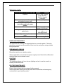
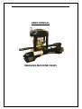
USER MANUAL
SWAGING MACHINE HE425
CONTENTS
USER MANUAL ............................................................................................... 1
WARRANTY CONDITIONS ............................................................................. 3
EC DECLARATION OF INCORPORATION. ................................................... 4
SAFETY REGULATIONS ................................................................................ 5
TECHNICAL DATA .......................................................................................... 6
HANDLING/TRANSPORT ............................................................................... 6
PRELIMINARY CHECKS ................................................................................. 6
LIGHTING ........................................................................................................ 6
ROUTINE MAINTENANCE .............................................................................. 6
OPERATING INSTRUCTIONS. ....................................................................... 7
RECALIBRATION ............................................................................................ 7
PROCEDURE TO BLEED THE SYSTEM........................................................ 8
MAINTENANCE AND SERVICE...................................................................... 8
SWAGE CHART ............................................................................................ 11
HE425 SPARE PARTS LIST ......................................................................... 12
OPTIONAL AIR/HYDRAULIC POWER PACK (700 BAR.) ............................ 13
SETTING INSTRUCTIONS........................................................................... 13
WARRANTY CONDITIONS
1. Note that all machines undergo strict testing before shipment.
2. All machines are warranted against any defects for a period of 6 MONTHS
starting from the date of delivery to the customer. The company reserves
the right to require a copy of the sales invoice.
3. We must verify defects. Therefore, each defective item must be returned to
our address with SHIPPING CHARGES PREPAID. We will return the item
with CARRIAGE FORWARD. ANY DELIVERIES TO OUR COMPANY
WITH CARRIAGE FORWARD WILL BE SENT BACK TO THE SENDER.
4. This warranty covers replacement and repair of any component found to
be defective.
5. Replacements and repairs completed under this warranty cannot extend
its 6 months validity.
6. This warranty does not cover any damages caused by deterioration from
use.
7. This warranty is not valid for damage resulting from incorrect operation, or
use not in compliance with the machine instructions.
8. This warranty is not valid in case of unauthorised machine modification.
9. This Instruction Manual is also to be considered as a warranty certificate,
with validity commencing from the date indicated on the freight bill.
EC DECLARATION OF INCORPORATION.
MANUFACTURER
ENDEAVOUR INTERNATIONAL LTD.
13 THE MALTINGS INDUSTRIAL ESTATE.
BATH.
ENGLAND.
BA1 3JL.
MACHINERY DESCRIPTION.
An eight segment hose assembly swaging head.
MODEL :-
HE425
SERIAL NO.
WARNING.
This machinery must not be put into service until the machinery into which it is
to be incorporated has been declared in conformity with the provisions of the
Directive.
Engineering Director.
This Declaration only applies when incomplete / un-powered equipment is
supplied by the Manufacturer
SAFETY REGULATIONS
Always work in safe conditions and with the necessary space around the
machine. Ensure that the machine is placed on a stable and appropriate
working surface.
1. DO NOT USE the equipment before reading the user manual.
2. CAUTION! If improperly used, the equipment may be dangerous and
may cause injury. Do not touch any moving parts.
3. CAUTION! It is absolutely essential that all working operations are
carried out by one operator only
4. This manual must be provided for the machine operator. Ensure that
the operator is aware of his/her responsibilities.
5. Guards must never be removed or tampered with.
6. (Where applicable) A fully trained and competent electrician must
connect the machine to the appropriate electricity supply.
7. Always wear protective gloves, safety glasses and appropriate clothing.
8. (Where applicable) Disconnect the power supply before removing any
covers, or attempting any maintenance of the machine
9. Only original spare parts can be used in the maintenance of the
machine.
TECHNICAL DATA
TECHNICAL/DIMENSIONAL DATA
Capacity
Pressure requirements for optional
air/hydraulic power pack
Packed Dimensions in mm
(excluding optional power
packs)
Controls
Voltage (Volts) optional electrical
power pack
Weight (Kg) without optional power
pack
Noise level
HE425
3/16”-11/2” (2 wire)
R1AT & R2AT
3/16”-1” (4 wire)
R9R/4SP
7 bar (100 psi)
520x730x800
Twin speed hand
pump (10,000 psi)
220-1-50HZ or 12volt
dc
255-440V/60HZ
85
Not exceeding 70dB
HANDLING/TRANSPORT
The machine will normally be shipped bolted to a wooden pallet . The bolts
should be removed and the machine lifted onto the work place using suitable
lifting equipment.
PRELIMINARY CHECKS
Place the machine on a stable surface.
Where applicable, ensure that the power supply line is fitted with a differential
safety breaker and overload cutout.
LIGHTING
The equipment does not have its own lighting and so it must be used in a
suitably illuminated area.
ROUTINE MAINTENANCE
Ensure that moving parts are always lightly greased.
Where applicable check periodically that the limit switches and emergency
controls are in good working order.
OPERATING INSTRUCTIONS.
A hand operated hydraulic pump operates the machine. (Item 1,Fig.1). When
the release valve (Item 2,Fig.1) is closed and the pump operated, the swaging
head will close and a hose assembly can be swaged.
To release the finished assembly unscrew the release valve two turns.
To operate the machine, select the appropriate die set using the die chart (Fig
3) in conjunction with the finished swage size required. Slide the dies into the
slot and ensure each die segment is fully supported by the die holder. (item 5,
fig 2)
Set the micrometer (Item1 ,Fig 2) to the required setting as determined from
the swaging chart. The numbers must be aligned with the indicator mark the
calibrator can be set at any intermediate position as required.
Close the release valve and operate the pump to close the dies onto the
assembly to be swaged. Ensure the ferrule is within the die length before
proceeding.
Operate the pump until the indicator rod (Item 2, Fig.2) is level with the top of
the micrometer adjuster. The swage is now complete. Initial swages should be
checked for swage size.
To remove completed assembly, unscrew the release valve and allow the
machine to open. The machine opening can be stopped by closing the
release valve and need not be fully opened each time.
RECALIBRATION
1. Fit the H28 die set to the machine
2. Set the calibrator to read 2 on the vertical strip and zero on the round
band.
3. Operate the machine and close the dies onto a 30mm diameter
mandrel. When the dies are closed onto the mandrel, operate the pump
for a further five full strokes to apply pressure to the mandrel.
4. Alter the adjusting screw to bring the indicator rod level with the top of
the calibrator and then lock into position with the nut.
5. Remove the mandrel and reset the calibrator to 4 on the vertical scale
and produce a swage.
6. Check the finished swage size. If the size is not within 0.1mm repeat
the calibration procedure.
PROCEDURE TO BLEED THE SYSTEM
1. Ensure the piston is fully retracted. Remove the bleed screw (item5, fig
1) and the oil filler plug (item 3, fig 1)
2. Slowly operate the pump to expel any air from the system. The system
is free from air when clear oil is being expelled through the bleed hole.
3. Replace and tighten the bleed screw.
4. Replenish the pump with SAE10 oil to the top of the tie rod (item 4, fig
1) and replace the oil filler plug. DO NOT OVER FILL
MAINTENANCE AND SERVICE.
For machines in regular use it is recommended that a monthly check on the oil
level in the pump is carried out. To check oil level, first ensure the machine is
fully open and then remove the oil filler (Item 4,Fig.1). The oil should be level
with the top of the tie rod (Item 5,Fig.1), that passes through the centre of the
pump. If required top up with SAE 10 hydraulic oil. DO NOT OVER FILL.
The sliding surfaces of the machine must be regularly lubricated with
molybdenum disulfide based grease.
At yearly intervals it is recommended that the calibration of the machine is
checked in accordance with the calibration instructions.
1
2
3
4
5
FIG 2.
SWAGE CHART
DIE
RANGE (mm)
L(mm)
*06
*08
*10
*13
16
22
28
34
40
*46
*52
06.0-07.9
08.0-09.9
10.0-12.9
13.0-15.9
16.0-21.9
22.0-27.9
28.0-33.9
34.0-39.9
40.0-45.9
46.0-51.9
52.0-57.9
40.00
40.00
40.00
40.00
40.00
50.00
50.00
60.00
60.00
70.00
70.00
Ferrule max
mm
18.00
20.00
22.00
25.00
28.00
34.00
40.00
46.00
52.00
58.00
64.00
*These dies not supplied as standard.
Calibration setting: select die set.
Micrometer setting = finished swage size – die size.
Example: To end up with a finished swage of 26mm.
Select 22 die, micrometer setting = 26-22 = 4mm.
HE425 SPARE PARTS LIST
Item No
1
2
3
Part No
300-093
300-091
300-092
2
3
1
Description
Seal Kit
Spring Kit
Calibrator Assembly
OPTIONAL AIR/HYDRAULIC POWER PACK (700 BAR.)
SETTING INSTRUCTIONS.
Connect the hose from the Swaging Head to the outlet connection of the
pump as indicated. Ensure pressure rating of the hose is suitable for 700 Bar
operation.
AIR SUPPLY.
Connect a suitable air supply to the air inlet connection of the foot pump as
indicated.
N.B. The air must be supplied using a filtered and lubricated supply, regulated
to a MAXIMUM operating pressure of 7 Bar (100psig).
PROCEDURE TO BLEED THE SYSTEM
The system will require bleeding if the foot pump was not supplied assembled
to the machine. The swaging machine will require positioning vertically, with
bleed screw facing upwards.
To bleed the system press down on the foot pedal and operate until the
machine piston raises approximately 15 to 20 mm. Release the foot pedal but
do not operate the release to lower the piston.
Loosen the bleed screw but do not remove, it is located in the centre of the
top face of the piston.
Air will be heard escaping from the bleed screw hole. When oil is seen at the
bleed screw hole and no more air is expelled, retighten the bleed screw. This
operation may need to be repeated if excess oil was lost whilst fitting the
pump, or if the operation of the unit is found not to be smooth. If the power
pack requires additional oil use ISO 32 oil where indicated.
OPERATING THE FOOT PUMP.
Set the Swaging Machine as stated in the operating manual.
Press down the Foot Pedal to close the head and perform the swage.
Release the Foot Pedal when the Calibration Indicator reaches its set
position.
To open the Head press down on the release part of the Foot Pedal.
The head need not be fully opened after each operation and can be stopped
at any position by releasing the Foot Pedal.