1
Donated by John & Susan Hansen - For Personal Use Only
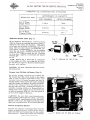
L-UNE MOTOR TRUCK SERVICE MANUAL
BRAKE SYSTEM
Index
Page 1
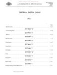
BRAKE GROUP
SPECIFICATIONS:
Air brakes •.
Hydraulic brakes
INDEX
Page
6,7
1,5
SECTION "A"
HYDRAULIC BRAKE SYSTEM:
Bleeding lines . • • . . • •
Brake pedal adjustment.
Care • • . . . . . . . . . . .
Check valve • • . . . . . • .
Hydraulic brake sys tern.
Hydraulic fluid . • . • • • . • . • .
Maintenance hints . . • . . . • . . • . .
Mas ter cylinder.' . • . • . . . . • . . •
Repairs to mas ter cylinder and wheel cylinders.
Wheel cylinders • . • . • . . . • . • • . . • . • • • . • . •
SECTION .. B'
3
2
2
2
1
1
3,4,5
1
2
2
t
HYDROVAC POWER BRA.KE UNITS:
Bleeding ins tructions • . .
Description . • • • . • . . • •
Hydrovac air inlet filter
Hydrovac check • . . . • .
Illus trations . . . . . . • .
Lubrication • • . . . . . • .
Vacuum connection service •.•
Vacuum line oil bath air cleaner.
4
4
5
6,7
1,2,3
.4
5
5
SECTION "C"
AIR BRAKE SYSTEM:
Air brake equipment.
Operation:
Charging.
Release.
Service application •••.
Ins truc lions . • . • . . . • .
Preventive Maintenance and Trouble Shooting:
Air leakage tes t. .
Inspection • . . • • . •
Operating tes ts ..
Service• • . . • • • • •
Trouble shooting ••
Air pressure gauge. •
• . • • .
.
Brake chamber (Bendix-Westinghouse).
Brake chamber - piston type (Midland).
Brake valve • . . . • • • • . . • . •
Brake valve - hand operated.•
Cut-out cocks . . • •
Double check valve . • . • . . .
F>RINT!O IN UNITEO STATtS 0" AMERICA
1,2
2
2
2
2,3
4
4
4
3,4
5
14
12,13
13,14
5,6
6,7
14
. •
8
( Continued)
Donated by John & Susan Hansen - For Personal Use Only
BRAKE SYSTEM Index Page 2
L-UNE MOTOR TRUCK SERVICE MANUAL
BRAKE GROUP (CONTINUED)
AIR BRAKE SYSTEM, SECTION "C" - CONTtD:
Drain cocks . . . . . . . .
~
Governor (type 0-1) . . . • • . . . . • . .
Hose and hose connections. • • • • . . • . • • • . • . . . . • • . • • • . • . •
Hose coupling and dummy couplings. • . • . • . . . • . . . • . • . . . • . •
Low pressure indicator . • . . • • • • . • . . . • . • • . . • . • . • . . . • . ,
Quick release valve .....
R ela y valve.. .. . . . , . . . .. . .. . .. . .. .. . . . . . . .. . . . .. . .. . .. . . . . . •
Reservoirs ............. .....
Safety valve ............. ... " ..............................................
Slack adjus ter ...............
Stop light switch•.
Tubing .... ,.
lit
lit
...
lit
....
lit
..
"
...
Page
15
..
8,9
. .
. ••••.•
. .
. •..•
............
.......................................................................
lit
It
(>
lit
................
lit
..................................
lit
It
..
......
...................................................
......................................
lit
..
.. . . .. .. .
.
..
.
.....................................
.
15,16
17
11,12
7,8
8
14,15
9,10
10,11
12
17
BRAKE SHOE ADJUSTMENTS AND SERVICING
SECTION "0"
L-llO, L-lll, L-1l2, L-120, L-121, L-122
Adjustment for wear (minor) . • • . • • . • . • • . .
Major adjustments and servicing.•
Parking brake cable adjustment . • . • • . . . . • .
2
2,3
2,3
SECTION !fE"
LM-120. LM-121, LM-122
Adjustment for wear (minor) . • . . . . . • . • . .
Major adjus tments and servicing. • . . • • . • . •
2
2,3
SECTION "F"
L-130, L-131. L-132
Adjus tment for wear (minor) . • . • . • . • . •
Major adjus tments and servicing.•••••••
2
2,3
SECTION fiG"
LB-140
Adjus tment for wear (minor) . . . . . . • • . • .
Major adjustments and servicing. • . • . • . • .
Parking brake cable adjustment . • . . . • . . .
2
2,3
2,3
SECTION "H"
L-150, LM-lSO, LM-lSl
Adjustment for wear (minor) . . . • . • . • . •
Major adjustments and servicing. • . • . • . •
2
2,3,4
SECTION Ifl"
L-lSl, L-lS2. L-IS3, LM-1S2
Adjus tment for wear (minor)
Major adjustments and servicing.
2
2,3,4
Donated by John & Susan Hansen - For Personal Use Only
BRAKE SYSTEM
Index
Page 3
L-LINE MOTOR TRUCK SERVICE MANUAL
BRAKE SHOE ADJUSTMENTS AND SERVICING (CONTINUED)
SECTION "J"
L-160,L-161,L-162,L-163,L-164,L-165,LC-160,LC-161,LC -162.L-170,L-17I,L-I72 L-173,L-174,L-175,LF-170,LF-17I,LF-I72 - FRONT BRAKE 12-1/8"x2-1/4 (TYPE "F") L-180,L-181,L-182,L-183,L-184,L-185.LC-180.LC-181,LC-l82 - FRONT BRAKE 13" x2-l/2" (TYPE "F") L-190,L-19l,L-192,L-193,L-194.L-195,LF-190,LF-19l.LF-l92,LC-190,LC-19l,LC-192,
L-200,L-20l,L-202.L-204.L-205,LC-200.LC-20l,LC-202 - FRONT BRAKE
15" x2-l/4" (TYPE "F")
Bleeding the hydraulic brake system. • • • • . • • . . . . • . . . • . • . . • . . • • • • • . • •
Brake adjus trnent. • . • • • . • . • • • . • . . . . . • . • • • . • • • . • . • . . . . • . • . . .
Brake component parts. • . • . • . • . • . . . . . • . . • . . . . . . • . • . • . . . • . . . • • . •
Removal of brake shoes. • . • . • . • . • . • • • . • . • • . . • . . . . . • . • . . . • . . . •
Removal of wheel cylinders • . • . • . • . . • • . • • • . • . . • • • • • . . • • . . • • . . •
Replacement of brake shoes • . • . . . • . . . . . • . • . . . . . • . . . . . • . . • • . . . .
Replacement of wheel cylinders . • • • • • • • . • . • • • • • . • . • . • . . . • • . . • . •
Service specifications • . . . • • . . • . • . . . • . . • . . • . • . • . • . • . • . . . • . . . .
Wheel cylinder assembly • • • . • . • . • . . • • . • . . . • . . . • . . . . . • . • • • . • . •
Wheel cylinder disassembly . . . . . . . . • . • . • • • . • . • . • . • . • • • . • . . . . . .
Page
5
4,5
2
3
3,4
4
4
5
4
4
SECTION "K"
L-160,L-16l,L-162,L-163,L-165,LC-160,LC-16l,LC-162 - REAR BRAKES 14-1/8" x 3" (TYPE "FR-2") L-164,L-170,L-17l,L-172,L-173,L-175,LF-170,LF-17l,LF-172,
REAR BRAKES 15" x 3" (TYPE "FR-2") L-174,L-180,L-18l,L-182,L-183,L-185,LC -180,LC-18l,LC-182,LF-190 LF-19I,LF-192 - REAR BRAKES 15" x4" (TYPE "FR-2") L2l0,L-2l1,LF-210,LF-2l1,LF-212,LF-220,LF-221,LF-222
FRONT BRAKES 16-1/2" x3-l/2" (TYPE "FR-2SII) L-204,L-210,L-211 - REAR BRAKES 16-1/2 11 x7-1/8" (TYPE "FR-2SD")
Bleeding the hydraulic brake system • • . . • . . . • . • . • • • . . . • . • . . • . . • .
Brake adjus trnent . • . . . • • . . • . . . • . . • . • . . . . • . . • . . • . • • • • • . • . . •
Brake component parts . . . • . . . • . • . • . • . . . . . • . • • • . . . • . . • . • • . . •
Removal of brake shoes . • . . • . . • . . . • . . . . • • • • • • • . • . . . . . . . . . . • . • . • .
Removal of shoe adjus Hng mechanism . • . • . . . • . • • • . • . • . • . . . • . . • • . • • • .
Removal of wheel cylinders • . . . • . . . . . • . • . . • . . . . • . • . • • . . . . • . . . • • • .
Replacement of shoe adjusting mechanism • • . . • . • • • . • . • • • • • • • . • • • . • • • .
Replacement of brake shoes • . • . . • . . • • . . . . • . • . • • • • • . • • • . • • • . • • . • • .
Replacement of wheel cy~inders . . . • . • . . . • • • . . . • . • . • . . . • . . . • . . . • • • •
Service specifications • . • • . . . . . . . . • . • . . . . . . . • . • . • • • . • . • . • . • • • . • •
Wheel cylinder as s embly; . • • • . • . • • . . . . • . • . • . • . . • • . • • • • • • • • . • • • .
Wheel cylinder disassembly . . • . _.••. , . . . • . • . • . • . • . . . • . • • • . • . • . • • •
11
10,11
2,4,6
8,9
8,9
9
10
10
10
12
9
9
SECTION ilL"
L-184,L-190,L-191,L"I92,L-193,L-195,LC-190,LC-191,LC-192,LF-2l 0,
LF-211,LF-220,LF-221,LF-222 - REAR BRAKES 16" X 4" (TYPE "FR")
L-194,L-200,L-201,L-202,L-205,LC-200,LC-20I,LC-202 - REAR BRAKES
16" x 5" (TYPE '! FR")
6
Bleeding the hydraulic brake system • • • . • • . . • . . . • . • • • • • • • • • • • . • • • • • •
5
Brake adjustment . . , " ... , . . . " . " " " " ..
2
Brake component parts . . • • . . . • . • • • . . • • . • • . . • . • . • • • . . • • . • • • • • . . •
3
Removal of brake shoes . • . • • • . • . • • • . • . • . . • • • • • • • • . • . • . • . • • • . •
4
Removal of shoe adjus ting mechanism . • • • . . . • . • • . . • . • • . . • . • • • . • . •
3,4
Removal of wheel cylinders • • • • • . • . . . • . . . • . • . • . . • • . ',' . . • • . . • • •
(Continued)
&
PRINYEO IN U,..ITED STATES OF' AMERlCA
•
"
•
"
•
"
•
"
••
"
••
"
"
"
•
"
•
"
•
"
•
"
••
Donated by John & Susan Hansen - For Personal Use Only
BRAKE SYSTEM
Index
Page 4
L-UNE MOTOR TRUCK SERVICE MANUAL
BRAKE SHOE ADJUSTMENTS AND SERVICING (CONTINUED)
SECTION til" (Con'd)
R eplacemen t of shoe adjus ting mechanism • . • • • . • • • . • . • . • . . . • . • . • . • • • .
Replacement of brake shoes . . • . • . . . . . • . • . • . • . . . . . . . • . • . • . . . • . • . • .
Replacement of wheel cylinders . . . • . • • • • . . • . . . • . • . . . • . • . . . • • . . • . • .
Service specifications • • . . . . . . . . • . . . • . • . • . . . . . • . • . • • • . . • . • . . • . . .
Wheel cylinder assembly • . • . . . • . . . • . • . • . • . • . . . • • . . • . . • • . • . • • • • • .
Wheel cylinder disass embly . • • . . . . . • . • . . • • . • . . . • . • . . . . . • . . . • . . . . .
Page
S
5
5
6
4
4
PARKING BRAKE ADJUSTMENTS
SECTION "M"
LM-120,L-130,L-ISO,LM-1SO,L-160,LG-160,L-170,LF-170 Series Trucks.
L-ISO,LG-lS0 Series Trucks. • . . • . . . • . • . . • • . . . • . • . • . . • • . . . .
L-190 and LF-190 Series Trucks; L-200, L-20l, L-202, L-204 Trucks. • •
L-20S,L-210,L-211,L-2l2,LF-2l0,LF-211,LF-212,LF-220,LF-221 ,LF-222
• • . • . •
. • . . • •
• • • • . •
Trucks.
.
•
.
•
•
•
•
•
.
•
•
•
1
1
2
2
Donated by John & Susan Hansen - For Personal Use Only
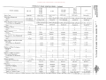
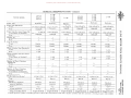
HYDRAULIC BRAKE SPECIFICATIONS
-
---
--
~-
--
~-
TRUCK MODEL
L-IIO
L-lli
L-112
L-120
L-121
L-122
Brake Type. . . • . • . • . • . • .
Hydraulic
Hydraulic
LM-120
LM-121
LM-122
Hydraulic
L-130
L-131
L-132
LB-140
Hydraulic
Hydraulic
L-150
L-151
L-152
L-153
LM-150
LM-151
Hydraulic
Hydraulic
Hydraulic
Brake Size (Standard): Front • . • . • • • . • . • . • . 12xl-3/4x3/16 12xl-3/4x3/16 12xl-3/4x3/16 12xl-3/4x3/16 12xl-3/4x3/16 12:l/ax2xl/4
Rear. _• . . . • . . . . . • • . . 12xl-3/4x3/16
12x2x3/16
12x2x3/16
14x2-1/4xl/4
14x2-1/4xl/4
14-I/ax3x3/8
12-ljax2xl/4
12-=-1/8x2xl/4 14-1/8x3x3/a
14x2-1/4xl/4
---
Brake Size (Increased Capacity):
Front (Same as Standard) .
· ..
~
~
-----~--
.
~
~
.. .
.........
~
..
· .. . . .
· . .. .
Number of Shoes: Front . . . . . . • . • . • . • .
2
2
2
Rear . . . • . . . . • • • • . . .
2
2
2
Single
Single
Rear . • . . . . . • . . . • _ ..
. .. .. .,
. ........
~
.. ..
. ..
.. . .. .
~
----
.
.......
.. .' ......
..
12-1/sx2xl/4
~
14-1/8x3x3/a
12-1/ax2xl/4
14-1/8x3x3/8
r
tz
[T1
c------
----
Type of Anchor:
Front • . . . • . . . • . • . • .
Single
2
2
2
2
2
2
2
2
2
2
Single
Single
--
Single
,-
--
Single
Rear . . . . . . . • . . . . . • .
Single
Single
Single
Single
Single
-----
Wheel Cylinder Size
(Standard) :
Front • . • . • . . • . . . . • .
~
Single
---
Single
Single ----
o
-1
o
:;;0
-1
:;;0
---
1
1
1
1-1/8
1-1/4
1-1/4
1-1/4
C
1
1
1-3/8
1-1/4
--
1-1/8
I
Rear ......' . • . . ., • . . . . .
I
I
1
n
7'
----
Wheel Cylinder Size
(Increased Capaci ty); Front (Same as Standard)
en ..
.
.. .
~
. .
......
---
Rear . . . . . . . . . • . • . • .
Number of Wheel Cylinders
(Standard): Front • • • . . . . . . . • . . .
.
.. .
.
.
· .......
. .. . . ..
.........
.........
~
. . .
..
. ..
..
~
· ........
.......
. ..... -
..
I
.
1-3/8
1
1
1
I
1
I
1
1
1
1
1
1
1
1
- .... " .
1
· ........
2
---
Rear . • . . . • . . . . . . • • .
Master Cylinder: Size (Bore and Stroke) . • .
Type . . . • • • . • . • • • . • •
<
n
1-3/8
[T1
Rear . • . . . • . . . • . • . • .
Number of Wheel Cylinders
(Increased Capacity):
Front (Same as Standard) .
~
I
· ......
. . "
. .
· " ......
.
.-
....
..
~
~
1
»
z
c
»
r
--
.
..
. - ...
..
.
..
..........
. .. . . .
-,
I
" ........
. ........
1
2
1-1!8xl-7/16
1-I/axl-7/16
l-r/axl-7/16
1-1/axl-7/16
1-1/8xl-7/16
1-1/axl-7/16
1-1/4xl-7/16
1-l/axl.7/16 Barrel
Barrel
Bar reI
Barrel
Barrel
Barrel
Barrel
Barrel
. .. .. . ..
· ........
c:>.ptional
Optional
.. . .
........
· ........
374000
.
.. .. . '" ..
. ... " ..
. .. .. . ..
· ........
. .. .
374000
.. C ..
ttl
(/)~
--
Hydrovac:
Standard or OptionaL . . • .
.
. . ..
.
.
. . ....
~,:'"
· ......
..
Serie s • . . . . . • . . . • . • .
· .. .. .
. . .. .
...... .
..
Cylinder Diameter • . . . . .
"
.....
· ...
"
Single or Tandem Piston •.
· .......
·"
....
Model No. (Bendix) . • . . .
~
"
------
---
"
...
..
. . .
.... "
'.. . ......
.
"
~
•
"
..
OIl
•
"C"
----
6-3/4"
6-3/4"
Single
Single
~~
.......
.........
..
.
.
"
... .
" "
'
...
. ....... ....
~
(/)
'tJo><: \I'\I'(/)
OQ
::r.
>-i
rogt"l
.... CIl:s::
Donated by John & Susan Hansen - For Personal Use Only
- . - .. -.............
IUCIltJ:I
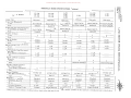
HYDRAULIC BRAKE SPECIFICATIONS - Continued
--
-
~-
TRUCK MODEL
L-I60
L-161
L-162
L-163
L-165
LM-152
L-164
LC-160
LC-161
LC-162
L-170 L-171
L-I72
L-173 L-175 L-174 ::r.o<
---
Brake Type . . . . . . . . . . . . . . .
Hydraulic
Brake Size (Standard):
Front . . . . . . . . • . . . . . . . .
I Z-I/8x2xl/ 4
Rear . • . • . . . . . . . • . . . . . .
14-1/8x3x3/8
--
Brake Size (Increased Capacity):
Front (Same as Standard) . . . .
.......
· . .. .
·
Rear . • . • . . . . . • . . . • . . . .
Number of Shoes:
Front . . . . • . . . • . • . . . . . .
Hydraulic
Hydraulic
Hydraulic
[y~
Hydraulic
'aulic
14-1/8x3x3/8
15x3x3/8
14-1/8x3x3/8
15x3x3/8
12-1/8x2-1/4x5/16 12-1/8x2-1/4x5/16 12-1/8x2-1/4x5/16 12-1/8x2-1/4x5/16 12-1/8x2-1/4x5/16
15x4x3/8
15x4x3/8
15x4x3/8
15x4x3/8
2
2
2
2
2
2
2
_15x5x3/8
2
2
Single
Double
Double
Double
Double
Double Rear . . . • . . . . . • . • . . . . . .
Double
Double
Double
Double
Double
Double
---
Rear . . . . . . . . . . . . . . . . . .
-:I
1-1/8
1-1/8
1-1/8
1-1/4
1-1/4
:;;0
1-3/8
1-3/8
1-3/8
1-3/8
1-1/2
1-1/2 n
......
1-1/8
1-1/8
1-1/8
1-1/4
· . " ..
1-3/8
1-3/8
1-3/8
1-1/2
·
(fJ
1-1/4
~ 1-1/2
<
---
n
2
2
2
2
2
Rear . . . . . . . . . • . • . . . . . •
2
2
2
2
2
2
.........
2
2
2
2
2
2
2
2
2
2
1-1/4xl-7/16
1-1/4xl-7/16
1-1/4xl-7/16
1-1/2xl-7/16
1-1/2xl-7/16
Barrel
Barrel
Barrel
Barrel
Standard
Standard
Standard
374000
374000
ltC"
374000
.. C ..
6-3/4"
6-3/4"
Type . . . . . . . • . . . • . _. . • . .
[T1 · .. . .
~
1-1/4xl-7/16
Barrel
~
>
Z
C
>
r
Barrel ---
Model No. (Bendix) . . . . . • . .
Series . . • . . . • . . . . . . . . . •
Cylinder Diameter . . . . . . . .
*
C
7'
1
Hydrovac:
Standard or Optional • . • . . . •'
~
1
Number of Wheel Cylinders
(Standard) :
Front .. _. . . . . . . . . . • . . . .
Master Cylinder:
Size (Bore and Stroke) . . . . . .
z
:;;0
---
Rear . . . . . . . • . . . . . . . . . •
~
C
~
2
Number of Wheel Cylinders
(Increased Capaci ty):
Front (Same as Standard) . . . .
IS:
[T1 2
Rear . . . . . . . . . . . . . . . • . •
l'1
15x4x3/8, 2
Wheel Cylinder Size (Increased
Capacity):
Front (Same as Standard) . . . .
8!II~cn
12-1/8x2-1/4x5/16 12-1/8x2-1/4x5/16 12-1/8x2-1/4x5/16 12-1/8x2-1/4x5/16 12-1/8x2-1/4x5/16
Rear . . . . . . . . . . . . . • . . . .
Type of Anchor: Front . . . . • . . . . • • . . . . . .
Wheel Cylinder Size (Standard):
Front . . . . • . . • • '. • . • . • . .
I» "d "
OQ~>
rot::;~
N .... 1:"l n
I»cn
~
.. . .
· . . ....
· .. .. .
· .. . ...
· ., .....
·'C
~
1
•
Standard
375279
*
Standard
375279
*
He"
"C" 9-1/2"
9-1/2" ---
6-3/4"
Single
Single (Guided)
Single or Tandem Piston . • . .
Single
Single
Single (Guided)
These hydrovacs contain a residual pressure check valve and must be used with a master cylinder that does not have a residual pressure check valve.
Donated by John & Susan Hansen - For Personal Use Only
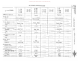
HYDRAULIC BRAKE SPECIFICATIONS - Continued
L-l80
L-18l
L-182
L-l83
L-185
L-184
Hydraulic
LC-180
LC-18l
LC-182
L-190
L-19l
L-l92
L-193
L-l95
Hydraulic
Hydraulic
Hydraulic
13x2-1/4x5/16
l3x2-l/4x5/16
13x2-1/4x5/16
15x2-1/4x5/l6
l5x4x3/8
l6x4x3/8
l5x4x3/8
16x4x3/8
LF-l70
LF-l71
LF-ln
TRUCK MODEL
L-194 -----
Brake Type . . . . . . . . • . . . . . •
Hydraulic
----
Hydraulic ---
Brake Size (Standard):
Front . . . . . . . . . . . . . . . . . 12-1/8x2-l/4x5/16
Rear . . . . . • . . . . . . . . . . . •
l5x3x3/8
l5x2-l/4x5/16
l6x5x3/8 ------
Brake Size (Increased Capacity):
Front (Same as Standard) . . . . l2-l/8x2-1/4x5/l6
r
13x2-l/4x5/16
l3x2-f/4x5/l6
13x2-l/4x5/l6
l5x2-1/4x5/l6
15x4x3/8
15x5x3/8
l6x5x3/8
l5x5x3/S
16x5x3/8
l6x6x3/8 .........
2
2
2
2
2
2
Rear . . . . . . . . . . . . . • . • . •
2
2
2
2
2
2
Rear . • . . . . . . . • . . . . . . . .
Number of Shoes: Front . . • . • . .
l5x2-l/4x5/l6
[TJ
Type of Anchor:
Front . . . . . . . . . . • . . . . . .
Double
Double
Double
Double
Double
Rear . . . • . . . . . . . . . . . • . .
Double
Double
Double
Double
Double
$:
Double
Double -----
Wheel Cylinder Size (Standard):
Front . . . . . . . . , . • . • . . . •
1-1/4
1-1/8
1-1/8
1-1/8
1-1/4
1-1/4 1-1/2
1-3/4
1-3/4
1-3/4
----
1-3/8
Rear . . . . . " . • . . . . . . • . . .
1-1/2
'Wheel Cylinder Size (Increased
Capacity):
Front (Same as Standard) . • . .
1-1/4
1-1/8
1-1/8
I-lis
1-1/4
Rear . . . • . . . . . . . . . . . . • .
1-3/8
1-1/2
1-1/2
1-1/2
1-3/4
Rear . • . • . . . . . . . • . . . • . •
1-1/4
-----
1-3/4 2
2
2
2
2
2
2
2
2
2
2
2
----
$:
2
2
2
2
Rear . . . . . . . . . . . . . . . . . .
2
2
2
2
2
2
1-3/4xl-7/16
1-1/2xl-7/16
1-1/2xl-7/16
1-1/2xl-7/l6
1-3/4xl-7/16
1 .3!"4xl-7/16
Barrel
Barrel
Barrel
Barrel
Barrel
Barrel Standard
Standard
Standard
Standard
Standard
375279
375278
!
---
Optional . . . . . . •
Model No. (Bendix) . . . . . • . .
Series. • • . . . • . . . . . . . • . . Cylinder Diameter. . • . . . • . .
Standard
375278
.. C ..
*
---
------
---
375279
------
*
375279
*' "C"
"C"
"C"
9-1/2"
9-1/2"
9-1/2' ,
*
375278
*
"C"
l~C'·
9-1/2"
9-1/2"
-----
-----
9-1/2"
~,
------
*
<
»
z
c
»
r
~-.
-_.---------
~
()
[TJ
2
Or
C
~
2
Type . . . . . • . . . . . . . . . . . •
;:j
()
Number of Wheel Cylinders
(Increased Capacity): Front (Same as Standard) . • . .
Master Cylinder:
Size (Bore and Stroke) . . . • . '.
~
Ul
Number of Wheel Cylinders (Standard):
Front . . . . . . . . . . . . . . • . .
Hydrovac:
Standard
tz
Single (Guided)
Single (Guided)
Single (Guided)
Single (Guided)
Single (Guided)
Single (Guided)
Single or Tandem Piston .__"__ .•
These hydrovacs contain a residual pressure check valve and .must be used with a master cylinder that does not have a residual pressure check valve.
b1
l:tI
~>
~ ~
oM
",.
;:!!(Il ,,0"'::
PlPI(Il
OQ ::r. I-i
CD§M
""tilts:
Donated by John & Susan Hansen - For Personal Use Only
"OC/ltJj
II' 't:l !:D
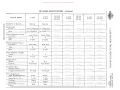
HYDRAULIC BRAKE SPECIFICATIONS - Continued
OQ~>
(\) I=::;~
~~
LF-190
LF-191
LF-192
TRUCK MODEL
L-200
L-201
L-202
L-20S
LC-190
LC-191
LC-I92
L-201
L-211
Hydraulic
Hydraulic
Hydraulic
L-204
-
II»~.
LC-200
LC-201
LC-202
t<:I
II'C/l
0:..::
OC/l
::s .,
-
(Il
Hydraulic
Brake Type . . . • . • . . . . . . . . . Hydraulic
Hydraulic
-
Brake Size (Standard):
Front • . • . . • . . . . . . . . • . •
ISx2-1/4xS/16
lSx2-1/4xS/16
lSx2-1j4xS/16
ISx2-1/4xS/16
12x.2-1/4xS/16
16-1/2x3-1/2xS/S
ISx4x3/S
16x4x3/8
16xSx3/8
16-1/2x7-1/8xS/S
l6xSx3/8
16-1/2x7-1/8xS/S
ISx2-1/4xS/16
lSx2-1/4xS/16
lSx2-1/4xS/16
15x2-1/4x5/16
- "' .....
15x5x3/8
16x5x3/8
16x6x3/8
2
2
2
2
2
2
2
2
2
2
4
Double
Double
Double
Double
Double
Double
Double
Rear . . . . . . . . . . . . . . . . . . .
Brake Size (Increased Capacity):
Front (Same as Standard) . • • .
Rear . • . . . • . • . . . . . • . . . •
10
•
..
..
,.,
...
Rear . . . . . . . . . • . . . . . . . .
2
-
Double
Rear . . . . . . . . . . . . . • . • . •
Double
--
-
Wheel Cylinder Size (Standard):
Front . . . . . . . . . . . _ • . • . .
1-1/4
1-1/4
1-1/2
Rear . . . . . . . . . . . . . . . • . .
Double
.~~
~-
1-1/4
1-1/4
1-3/4
1-3/4
1-S/8
1-1/4
1-1/4
1-1/4
Rear . . . . . . . . . . . . • . . • _ •
1-1/2
1-3/4
1-3/4
. .....
Number of Wheel Cylinders
(Standard) :
Front. . . . . . . . . . . . . . . . . .
2
2
2
Rear . . . . . . . . . . . • . • . • . •
2
2
2
Number of Wheel Cylinders
(Increased Capacity):
Front (Same as Standard) . . • •
l
2
2
"
2
2
2
.
1-3/4x2-1/2
1-3/4xl-7/16
1-3/4xl-7/16
Barrel
Barrel
Rear . . • . . . . . . . . . . . . . . .
)I/laster Cylinder:
Size (Bore and Stroke) • . . • . •
Barrel
Type . . . • . . . • . • . . • . . . . • Hydrovac: Standard or Optional . . • . . . . 3:
~
o
f--
Double
~
Double
-
-l
1-1/4
1-1/2
1-3/4
1,5/8
~
C
(')
..
~
. .. ..
(J)
1-1/4
....
II'
[11
...
1-3/4
· ....... ~
2
2
2
[11
2 Siamese Twin-type
2
2 Siamese Twin-type 3:
........ . .
. .
1-3/4x2-1/2
Barrel
2
· .....
· . ..
1-3/4xl-7/16
1-3/4x2-1/2
2
'"
Barrel
Barrel
-
Standard
Model No. (Bendix) . . . • • . . . 374229
*
Standard
375278
-
* These
tz
.....
7\
Wheel Cylinder Size (Increased
Capacity):
Front (Same as Standard) . • . .
Diameter . . . . . . . • Single or Tandem Piston . . . . "
-
Type of Anchor:
Front . . • . • . • . . . . . • . • . .
~linder
.
r
[11
Number of Shoes:
Front . . • . • . . . . . . . . . . . .
Series . . • . . . . . . . • . • . • . • 16x6x:?/S
t<:I
~
\lC"
9-1/2"
Tandem
*
Standard
375278
*
Standard
374230
*
Standard
375278
*
Standard
374230
*
~(C~'
·"C't
"C"
"C"
"Ct'
9-1/2"
Single (Guided)
9-1/2"
Single (Guided)
9-1/2"
Tandem
9- 1/2"
Single (Guided)
9-1/2"
Tandem
hydrovacs contain a residual pressure check valve and must be used with a master cylinder that does not have a residual pressure check valve.
o<
»
z
c
»
r
Donated by John & Susan Hansen - For Personal Use Only
HYDRAULIC BRAKE SPECIFICATIONS - Continued
TRUCK MODEL
LF-210
LF-211
LF-212
L-220
L-225
LF-160
LF-221
LF-222
Brake Type • . . . . . . . . . • . . . .
Hydraulic
· .......
Hydraulic
Brake Size (Standard):
Front . . • . . . • . . . • . . . . . . 16-1/2x3-1/Zxs/s
16x4x3/8
Rear . . . • . . . . . . . • . • . • . •
Brake Size (Increased Capacity):
Front (Same as Standard) . . . •
Rear . • . • . . . . . . . • . . . • . .
Number of Shoes:
Front . . • . . . • . • . . . . . • . .
.
.
....
"
.
16x4x3/8
.. .. ..
.
...........
. .. .
..........
·.
. ....
.
·.
. . .
· ..
2.
........
. ..
2
Rear . . . . . . . • . . . . . . . . . .
· . . ..
-------
.
.
.
2
2
LF-230
LF-23l
.....
· ...... ..
...... . ...
.. ........
16-1/Zx3-1/Zxs/s
"
L-230
L-231
---
----
.. .
.
.
"
........
.
...
.
......
Double
........
<-
Double
"
.......
Rear . • . • . . . . . • . . . . . • . •
Double
.
....
..
Double
..
......
-------
Wheel Cylinder Size (Standard):
Front • . . . . . • . . . . . . . • . •
I-liz
.
......
I-liz
-.
Rear . . . . . . . • . . . . . . . • . •
1-3/4
..........
1-3/4
.. ........
Rear . . . . . . . . . • . . . . . . . .
Number of Wheel Cylinders
(Standard) :
Front • . . . . . . . . . . . . . . . .
· .. - ...
.
. .. . ..
. ..
.
2
..
.
..
......
....
..
. .
. ..
"
-----
· ........
2
.
2
..
. ..
·
2
Rear . . . . . . . . . . . . . . . . . .
Number of Wheel Cylinders
(Increased Capacity):
Front (Same as Standard) . . . .
-----
· ........
.. .. . .
Rear . . . . . . . • . . . • . . . . . .
---
~
. .
..........
.
.
- ..... ..
----~---
1-3/4x2-1/2
· .......
Barrel
Barrel
·.
Standard
-----
Model No. {Bendix} ., . . . . . . •
Series . . . . . . .
.
~
,.
"
.
.
~
..
374230
*
9-1/2"
Single or Tanden Piston . . . . .
Tandem
. ..
....
~
-----
........
.
~
["l1
----
......... .
tz
----
$:
o
...;
o
;::0
... - .
..
. .. .
...;
~
.. ........
· ........ ()
· ....... U>
.
------
.....
;::0
· ........
.
........
n<
["l1
..
· " .....
$:
·
z
c::
..
to
...
:r>
"
.. ........
1-3/4xZ-I/Z
.
["l1
........
. .. . .
........
<0 ..
..
..
..
Standard
*
...
0
· . ...
· . . . ..
'·C'l
9-1/Z"
.
·.. .
Tandem
..
•
"
•
II>
•
"
.
. ..
~
.. .
~
,.
......
· ........
.......
... " .
-------
· ......
. . ., .
~
----
........
.
374Z30
"
-----
*
----
..
., .,
"
~IC"
Cylinder Diameter • . . . • . . . .
-------
,
r
.
. .
· ........ ---
---
Hydrovac:
Standard or Optional • . . . . . .
..
...
.
. . ..
-----
Type . . . . . . . . . . . • . . . . . .
.
A
Wheel Cylinder Size (Increased
Capacity):
Front (Same as Standard) . • . .
Master Cylinder:
Size (Bore and Stroke) . . . . . .
. .. .
........ .........
Type of Anchor:
Front . . . . . . . . • . . . • . . . .
.,
.
. .
,.
.
.....
"
..
,.
..
~
..
~
.
----
:r> r
---~
. .
tl1
~
C/l~
"
...
· ......
· .. . .
· ......
~
These hydrovacs contain a residual pressure check valve and must be used with a master cylinder that does not have a residual pressure check valve.
'g~
ntri
I::;
.... C/l
'"cJn><
III III C/l
OQ
::r."
lI>§tri
V\D>iS':
Donated by John & Susan Hansen - For Personal Use Only
1jtlltJj
AIR BRAKE SPECIFICATIONS
TRUCK MODEL
L-IBO
L-IBl
L-IBl
L-IBS
L-IB4
L-190
L-191
L-l92
L-19S
LC-IBO
LC-IBI
LC-IBl
LF-190
LF-191
LF-192
III 'tI ::tl
OQ~>
(\)I::;~
L-194
L-lOO
L-201
L-202
L-20S
LC-190
LC-191
LC-l92
LC-lOO
LC-201
LC-202
O'h' M
III til
::r.-<
o til
i:I ,...:j
Ul
M
~
Standard or Special. • . •
Special
Brake Size:
Front . . . . • . . . . . . l6xl-l/4xS/16
Rear . . . . • . • . . "
Brake Chamber-Front:
Location. . . . . . • . .
16xS-l/lxl/l
. • • . •
Special
• . • . •
• . • . •
Special
....•
• • • . •
l6xl-l/4xS/16
• . • • .
. . . . •
16xl-l/4xS/16
•.•.•
. . • . .
16-l/lx6x3/4
. . • . .
• . • • •
16-1/2x6x3/4
•.•.•
[TJ
Back. Plate
• . • . •
Back. Plate
• • • . •
. . • . •
Back. Plate
.••.•
Type . • • . . . . . . . .
E
. . . . .
E
• • • . •
. . • . •
E
. . •.•
Size.. . . . • . . . • . .
6-3/16
• . • . •
6-3/16
• . • • •
. . • • .
6-3/16
.••••
Axle Pad
. • • . .
Axle Pad
. • • . •
• . . . •
Axle Pad
•.•..
C
. . • . .
C
• • • . •
. . • . •
B
••••.
. . • . •
9-3/16
•.•.•
Brake Chamber-Rear:
Location. . • . . . . . •
Type . . • . • . . . . . •
Slack Adjuster Length:
Front • . • . • . . . . . •
Rear • . • • • . • . • • •
B-l/16
• . . • .
-
9-3/16
• • . . •
Control. • . . . . . . . .
Air Reservoir:
Number Used. . . . . •
Length and Diameter.
Air Compressor:
Type (Westinghouse).
Capacity in Cu. Ft . •
Cooling. • . • . • . . . •
Mounting. • • . • • • . •
Drive.. • . . . • . • . •
~
o~
~
C
()
A
tf)
[TJ
3-3/B
6
•.•.•
. . . . .
4
•.•.•
..•.•
6
• . • . •
• . • . •
-
Brake Valve:
Model. . • . • . • . • . .
3:
--1
-
Size.... . • . • • . . . . •
r:
cz
S
•....
7
-
•.•.•
-
~
n
[TJ
~
3:
D-l
• . • . •
D-l
. . . • •
. . • . •
D-l
. . • . •
Foot Pedal
. . . . .
Foot Pedal
. . • . •
. . • . •
Foot Pedal
.••••
1
. . . . .
1
. • • • .
• . • . •
1
•.•.•
4l-1/lxB
• . . • •
4l-l/2xB
. • • . •
• . • . •
41-1/lx8
•.•••
l-Cyl.
. • • . •
l-Cyl.
. . • . •
• .•. ,
2-Cyl.
• , •.•
7-1/4
• . • . •
7-1/4
• . • . •
• • • • .
• , • • •
. . . • .
Water
••••, •
...... • .•
• , • • •
_ ~ _~ ._~.~
Engine
__ 13~lt
·Water
... , •
_
Water
Engine
• , • . •
Engine
.J?e!:f; ____ ._--,,- ._~._,---.~Belt __ __
7-1/4
----
•••••
•.•.•
• , •.•
_._'....:.._._.'---_
»
z
c
»
r
Donated by John & Susan Hansen - For Personal Use Only
AIR BRAKE SPECIFICATIONS - Continued
---
TRUCK MODEL
L-2l0 L-2l1 L-204 LF-210 LF-211
LF-ZIZ LF-220
LF-Z21
LF-222
L-220
L-2Z5
LF-230
LF-Z31
L-230
L-Z31
---------
Standard or Special. • . . .
Special
Special
•
..
..
..
..
<II
..
«>
..
.. .. .. .
..
.
.. ..
.
.
..
..
"
to
..
..
--------
Brake Size:
Front . .
~
..••.....
16xZ-I/4x5/16
l7-1/4x3x3/a
.. .
.
..
.
l6-l/Zx7x3/4
..
(j.
.. •
. . .. ..
..
.. ., ..
..
..
.. .. . .. ..
..
dO
..
..
..
.
..
.
..
. .. .
.. .. .. ..
------
Rear . • • . • . • . • . • . 16-I/Zx7x3/4
Brake Chalnber- Front: Location . . . . . . • . • .
Back. Plate
Back. Plate
..
.. . ..
. ..
. .. . . ..
. .. .. . .
. . . .. .
. . . .. ..
Type . . • . . . • . . . • .
E
A
Size . . . . . • . • . . . • .
6-3/16
6-15/16
..
.
. .. . .. ..
Axle Pad
Axle Pad
.. .. . . .
. .. .. . .
Brake Chalnber-Rear:
Location • . . . . . • . . .
..
. .
.
..
.. ..
G
G
Size . . . . . • . . . . . . .
9-7/a
9-7/a
. .. .
.. .
,.
.
. . ..
..
'"
GI
..
..
.. .. ..
..
· .. .
"
Rear • . • . .- • • . • • • .
Brake Valve:
Model. . . . • . • . . . • .
Control. • . • . . . • . • .
Air Reservoir:
NUlnber Used •••••.•
Length and Dialneter . .
5
5
.......
00<
6-l/Z
6-1/2
. .. . .. ..
D-I
D-I
. . .. . ..
.. . .. . .
Foot Pedal
Foot Pedal
I
1
4l-l/Zxa
4l-l/2xa
..
It ..
..
.. ..
..
..
....
Z-Cyl.
Capacity Cu. Ft• . • . . .
Cooling . • . . . • . . . . .
7-1/4
Water
7-1/4
Water
Mounting. . • . • • • • . .
Engine
Engine
Drive . . . . . . . . • . • .
Belt
Belt
·. .
'"
<»
•
· .. .
'" ..
,. '"
'"
'"
'"
.
..
'"
· . . . '"
«>
..
. .. . .. . ..
It
..
..
..
..
~
..
..
1:1
..
..
.. ....
. .. .. ..
...... .. .. .. .. ..
. ..
.. ..
..
..
a
..
..
..
. . .. .
a
..
..
•
.
------
. .. ..
. ..
..
..
.
..
. .. ..
.
~
.
------
.
..
. . ..
"'
.. . . . ..
..
..
.
..
.
.
.. .. .
..
..
..
Ii)
..
.
......
"
.
..
.. ..
..
..
..
..
..
..
..
. '" . '"
'" . '" '" '"
. .. . . .
. . '" . .
..
..
f)
..
..
..
.
..
..
..
.. ..
. ..
..
'"
. .. .. ..
..
..
..
G
..
..
..
..
<;I
..
~
o
-l
o
:A)
-l
:A)
C
n
~
(J)
fT1
.. .
:A)
"
n
fT1
.. .. . ........ .. .. .. .. .. r------------
------
.
.. ..
.
.. ..
. .. .
.. . .
. ..
..
<
~
»
z
c
»
r
----~
. . . ..
.. . . .
.. .
'"
'"
'" '" - -..- - -'"- '"
..
.. " .
.. ..
------
Z-Cyl.
..
..
------
Air COlnfressor:
Type Westinghouse) •.
.
..
..
------
Slack Adjuster Length: Front • . • . . . • . . . • .
<0
..
.. ..
..
r:
cZ
fT1
. . .. . .
..
.. .. . . ..
.. . .
.. ""
.. .. ..
------
Type . . • . . . . . . . • .
.
'"
..
----~
~
'"
.
'"
•
....
a
a
,.
'"
'"
. . . ..
· .. . .
..
..
.. '"
'"
0
•
OJ
· ....
OJ
•
'"
..
•
OJ
'"
...
· . . . ..
. ..
· . . . .. ~
..
tJj
l:Q
1Zl»
]~
t-'
~1Zl
'1:l n O-<
IUIUIZl
(lQ p: ~
(1) 0
tx:l
-.Jg~
Donated by John & Susan Hansen - For Personal Use Only
Donated by John & Susan Hansen - For Personal Use Only
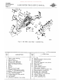
L-UNE MOTOR TRUCK SERVICE MANUAL
BRAKES
HYDRAULIC
Section A
Page 1
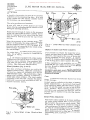
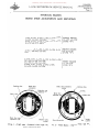
HYDRAULIC BRAKES HYDRAULIC BRAKE SYSTEM
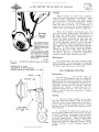
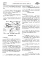
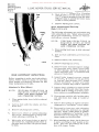
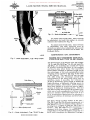
compensating port (C) and the pressure stroke
commences.
The hydraulic system used to actuate the brake
mechanism consists of a compensating type
master cylinder in which the hydraulic pressure
is originated; individual wheel cylinders, in
which the hydraulic pressure is applied, which
serve to actuate the brake shoes against the
br ake drum of each wheel; and the "Line" con
sisting of steel tubing, flexible hose, brackets
and unions, interconnecting the master cylinder
and wheel cylinders. The master cylinder and
wheel cylinders are fitted with pistons, all of
which are provided with cup packings, which
act as a seal to maintain pressure and prevent
loss of brake fluid.
Actual pressure is not built up until the fluid
displaced has caused all shoes to go into con
tact with their drums. Additional pressure
on the pedal produces hydraulic pressure within
the brake system.
Depressing the brake pedal moves the piston
within the master cylinder, thus displacing the
brake fluid from the master cylinder through its
outlet orifices, tubing and flexible hose con
nections into the wheel cylinders. The brake
fluid, being noncompressible, enters each of
the wheel cylinders, causing the cylinder pistons
to move outward and actuate the brake shoes.
As pressure on the pedal is increased, greater
hydraulic pressure is built up within the wheel
cylinders, and consequently greater force is
exerted against the shoes.
When the pressure on the pedal is released.
the brake shoe retracting springs return the brake
shoes to their normal or released position. The
return movement of the brake shoes, in turn,
c·auses movement of the wheel cylinder pistons
toward their released position. thus forcing
the fluid back thru the tubing into the master
cylinder.
HydrauliC
F~uid
Always use genuine "Lockheed" or other high
grade automotive type brake fluid. The use of
other than genuine "Lockheed" or any high grade
automotive type brake fluid or the introduction of
mineral base oil into the system will cause
rubber parts to swell and become inoperative.
Removal of operator's foot from the brake
pedal after each brake application permits
the brake pedal and push rod (A) to return
independently to their off-position.
The return of piston (B) and cup (D) is accom
plished by the piston return spring (I).
The piston for this type of unit is designed to
carry a primary cup (D) and a secondary cup
(E). The construction of the piston is such that
reserve fluid from the tank passes through
vent (R) in a recessed area. Thus we have
fluid on both sides of the primary cup. The
secondary cup (E) is merely a seal to prevent
loss of reserve fluid into boot (G).
The combination type master cylinder is also
known as a compensating type. Its primary
compensating function is to maintain a constant
volume of fluid in the system at all times, re
gardless of expansion (heat) or contraction
(cold). The secondary compensating function is
the replacement of additional fluid into the system
to counterbalance any loss due to gravity seepage.
The return to off-position of piston (B) and cup
(D) is much faster in displaced volume than the
return of the fluid through fitting (J) into the
master cylinder. A momentary vacuum is
created in the cylinder barrel and additional
fluid is drawn into the system through the drilled
holes in piston (B) and past the lip of cup (D).
The operating fluid returns more slowly from
the wheel cylinders and lines back into the master
cylinder barrel. Any excess is by-passed by port
(C) into the reservoir. Thus we have a cylinder
full of fluid for the next brake application.
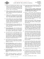
Combination Type Master Cylinder (Fig. 1)
The combination type master cylinder consists
of barrel and tank casting, double check valve
(L), piston cup return spring (I), piston cup (D),
piston (B), piston stop (p). boot (G) and connecting
link (A).
L
.
The fluid reservoir or supply tank is cast in
tegral over the master cylinder barrel. A com
bination filler and breather plug (N) permits
atmospheric pressure on the reserve fluid at
all times.
Depression of the pedal causes piston (B) and
cup (D) to move forward in the cylinder barrel.
A very small forward movement of cup (D) closes
PRINTED IN uNITED STA.TES OF AM£RtCA
IHllli!l"ot--J
A G
Fig. I
inder.
E
B
D
A·22934
Typical Combination Type Master Cyl
Donated by John & Susan Hansen - For Personal Use Only
BRAKES
HYDRAULIC
Section A
Page 2
L-UNE MOTOR TRUCK SERVICE MANUAL
Check Valve
Boot
Cup
Piston spring
A double check valve is used in all master
cylinders of the compensating type. It is held
in the closed end of the master cylinder barrel
by the piston cup return spring.
The valve performs two functions:
It acts as~ a seal to prevent fluid or air being
drawn into the system through the bleeder screw
during the bleeding operation.
Fluid passed through the valve on the pressure
stroke can return into the master cylinder barrel
only by raising the entire valve from its seat.
The valve is held in place by the cup return
spring.
When the pressure on the returning fluid drops
below 6 to 8 pounds, the spring closes the valve
and the system is under a slight pressure. This
pressure will not cause the shoes to drag. It is
used to assure a positive seal at the wheel cylin
der cup packings.
The valve does not control brake pedal move
ment. Do not try to remedy this complaint by
changing the valve.
NOTE: On vehicles equipped with certain models
of Hydrovacs the check valve is located in the
Hydrovac slave cylinder tube; and where this
is the case, no check valve is used in the master
cylinder. (See Hydrovac Specifications.)
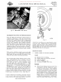
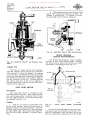
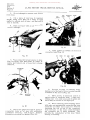
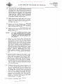
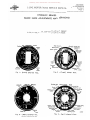
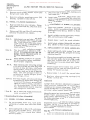
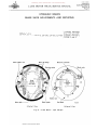
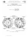
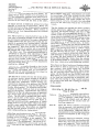
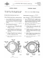
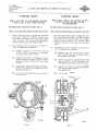
Wheel Cylinders (Fig. 2 and 3)
Two types of wheel cylinders are used in the
hydraulic brake system. Different combinations
of these two types of cylinders are used on
different model trucks. Fig. 2 illustrates a single
piston wheel cylinder, and Fig. 3 illustrates a
double piston wheel cylinder. The wheel cylinder
assembly is the unit that changes the applied
hydraulic pressure into mechanical force to
actuate the brake shoes.
Piston spring Piston 141---
Bleeder valve
A-22728
Fig. 3 type) •
Typical Wheel Cylinder (Oouble-piston
Repairs to Master and Wheel Cylinders
It is possible to rehone the majority of cyl
inders and place them in good working condition;
however, this requires the use of up-to-date
honing equipment and plug gauges. A cylinder
hone kit is available under number SE-1679,and
a set of plug gauges under number SE-IOOO.
If this equipment is not available, we recom
mend that the unit be taken to the nearest Wagner
Service Branch or Authorized Service Station
for repairing,
Cylinders and parts must not be washed in
gasoline, kerosene or oil. Use high-grade
denatured alcohol.
Care
Keep all lubricant and brake fluid away from
brake linings.
Inspect master cylinder at the time of making
brake adjustments -- for correct fluid level.
Fluid should be within 3/8" from bottom of filler
neck. Do not fill supply reservoir to top of filler
neck. Caution: When removing supply reser
voir filler cap, extreme care must be used to
prevent dirt or moisture from entering master
cylinder.
Brake pedal Adjustment
A-22743
Fig.2 ty pe).
Typical Wheel Cylinder (Single-piston
When brake control system is in release position,
foot brake pedal should have 1/4" free travel
(Fig. 4) before the pressure stroke starts. This
free travel is required to prevent blocking of
compensating port in master cylinder. Brakes
will drag if compensating port becomes blocked
due to pressure building up in the system.
Shorten pedal push-rod to allow piston to uncover
compensating port, allowing fluid to escape into
tank.
Donated by John & Susan Hansen - For Personal Use Only
L-LINE MOTOR TRUCK SERVICE MANUAL
BRAKES
HYDRAULIC
Section A
Page 3
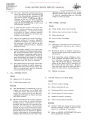
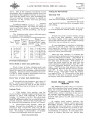
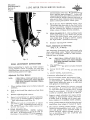
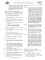
Fig. q - Brake Pedal Free Travel.
Bleeding The Lines (Also see Hydrovac Section)
Any air inside the hydraulic system must be
removed. Whenever a line has been discon
nected at master cylinder, the entire system must
be bled at all wheels until all air is com.pletely
expelled. When a line has been disconnected
at any wheel cylinder, this cylinder together
with the cylinder on the opposite wheel must be
bled. Air in the system will cause a springy,
rubbery action of the brake pedal. Should a
sufficient quantity be introduced into the system,
the brake pedal will go to toe board under norm.al
pressure.
Fig, 5
which the cleanliness is questionable should
never be used. Fluid should be replenished in
supply reservoir after each cylinder is bled.
Should supply reservoir be drained during bleed
ing operation, air will enter the system and re
bleeding will then be necessary.
Maintenance Hints
Fill master cylinder supply reservoir with
genuine Lockheed or any high grade automotive
type brake fluid and see that it is kept at least
half full during entire bleeding operation.
Use pressure-type brake bleeder where avail
able. Attach bleeder tube to bleeder valve by
pushing tube over the end of bleeder valve.
Allow tube to hang in a clean container, such
as a pint glass jar. Unscrew bleeder valve
3/4 turn and depress brake pedal by hand, using
half strokes, allowing pedal to return slowly.
Pumping brake pedal forces fluid out into glass
jar, and carries with it any air which might be
present in the system. Watch flow of fluid from
tube, the end of which should be kept below sur
face of fluid in pint bottle, and when all air
bubbles cease to appear or when streamis a solid
fluid mass, close bleeder valve. (See Fig. 5.)
Fluid withdrawn in bleeding operation should
not be used again, unless absolutely certain
that it does not contain iITlpurities. Fluid of
PR!N'r~O
IN UNltEO STATES OF' AMERICA
1. PEDAL GOES TO FLOOR BOARD:
(a) (b) (c) (d) Normal wear of lining.
Brake shoes not properly adjusted.
Leak in system.
Air in system.
(e) Pedal improperly set.
(f) No fluid in supply reservoir.
(a) When brake linings become worn it is
necessary to set the shoes 'into closer
relation to bra.ke drums. This condition
is usually accompanied by the remark
that it is necessary to pump the pedal
several times before a brake is obtained.
Shoes should be set in accordance with
instructions on ADJUSTMENTS FOR
WEAR. Do not disturb anchor pins when
ITlaking this adjustment. Adjustment
must be made while drums are cool.
Donated by John & Susan Hansen - For Personal Use Only
BRAKES
HYDRAULIC
Section A Page 4
L-LiNE MOTOR TRUCK SERVICE MANUAL
(b) In cases where the anchor pins have
been disturbed and the relation of the
arc of the shoes to drums changed, lining
will wear rapidly and the braking ef
ficiency of that particular wheel will be
reduced. To overcome this condition,
follow instructions as outlined in
MAJOR ADJUSTMENTS, brake shoe
adjustment sections.
(c) A leak in the system will allow the
pedal, under pressure, to go to toe
board gradually. If no leaks are found
at wheels or joints, remove master
cylinder and check bore of barrel for
scores or scratches.
(d) Air in the system will cause a springy,
rubbery action of the pedal. Should a
sufficient quantity be introduced' into
the system, the pedal will go to toe
board under normal pressure. System
should be bled,
(e) Brake pedals should be set to give the
correct amount of free movement before
the pressure stroke starts. Excessive
free movement reduces the active travel
of the master cylinder piston, which in
turn determines the amount of working
fluid to be expelled from the master
cylinder into the lines or system.
(f) The fluid level in the supply reservoir
should be checked at regular intervals.
Should the reservoir become empty, air
will be introduced into the system,
necessitating bleeding.
gradually build up and brakes drag.
Shorten pedal push rod to allow piston
to uncover compensating port, allowing
fluid to return to tank.
3. ONE WHEEL DRAGS:
(a) Weak brake shoe return spring.
(b) Brake shoe set too close to drum.
(c) Cups distorted.
(d) Loose wheel bearings.
Remedy
(a) Springs sometimes lose their con
tracting power and take a set. Replace
spring.
(b) Readjust shoes to proper clearance.
Do not change anchor pin setting unless
necessary.
(c) If in repairing wheel cylinders, kero
sene, gasoline and other fluids are used
as a cleaner, instead of alcohol, the
cups will swell and distort. The return
action of the shoes will be retarded and
the brake drum will heat. Replace
cups and wash unit in alcohol and dip all
parts in fluid before reassembling.
(d) Tighten bearings.
Z. ALL BRAKES DRAG:
4. TRUCK PULLS TO ONE SIDE:
(a) Mineral oil in system.
(b) Pedal improperly set.
(a) Grease-soaked lining.
(b) Shoes improperly set.
(a) The introduction of mineral oil, such as
engine oil, kerosene, or any fluid with
a mj,neral base, into the system will
cause the cups to swell and distort,
making it necessary to replace all cups
and flush system.
(b) Directly ahead of the master cylinder
piston cup (when in normal release
position) is a relief port. It is im
perative that this port be open when the
brakes are released. Brake pedal
should be set to give the proper free
movement before pressure stroke begins.
Should this port be blocked by piston
cup not returning to its proper release
position, the pressure in the system will
(c) Backing plates loose on axle.
(d) Front spring U-bolts loose.
(e) Different makes of lining.
(f) Tires not properly inflated.
(a) Replace with new lining of same make'.
Grease-soaked linings cannot be sal
vaged by washing or cleaning.
(b) Refer to MAJOR ADJUST1YlENTS, brake
shoe adjustment sections.
Donated by John & Susan Hansen - For Personal Use Only
L-UNE MOTOR TRUCK SERVICE MANUAL
(c) Loose backing plates perlTIit the brake
asselTIbly to shift on the locating bolts.
This shifting changes the predeterlTIined
centers and causes unequal efficiency.
Tighten backing plate and readjust shoes
with feeler gauge.
(d) Loose spring U-bolts perlTIit the axle to
shift on the springs and run out of line.
This is noticed especially when a high
braking torque is developed. Tighten
U-bolts at their proper location on
spring.
7. BRAKES
HYDRAULIC
Section A
Page 5
LIGHT PRESSURE ON PEDAL, SEVERE
BRAKES:
Cause
(a) Brake shoes not properly adjusted.
(b) Loose backing plate on axles.
(c)
Grease-soaked lining. RelTIedy (a) Consult relTIedy (b) under No.4.
(e) Different ITIakes of linings have different
braking efficiency. Two different lTIakes.
one with high efficiency and one with low
efficiency, would cause truck to pull to
one side.
(f) All tires should be properly inflated.
5. SPRINGY, SPONGY PEDAL:
Cause
(a) Brakes shoes not properly adjusted.
(b)
Air in systelTI. RelTIedy (a) Consult relTIedy (b) under No. 1.
(b) Consult relTIedy (d) under No.1.
6. EXCESSIVE PRESSURE ON PEDAL, POOR
STOP:
Cause
(a) Brake shoes not properly adjusted.
(b) lITIpr oper lining.
(c) Oil in lining.
(d)
Lining lTIaking partial contact. RelTIedy (a) Consult relTIedy (b) under No. 1.
(b) Specified linings have been developed
to give satisfactory service and no
changes should be lTIade in the field to
other lTIakes of linings.
(c) Replace shoes.
(d) RelTIove high spots.
PRINTEO IN
UNIT~C
STATI;S OF AMERICA
(b) Consult relTIedy (c) under No.4.
(c) Consult relTIedy (a) under No.4.
Donated by John & Susan Hansen - For Personal Use Only
Donated by John & Susan Hansen - For Personal Use Only
L-LINE MOTOR TRUCK SERVICE MANUAL
BRAKES
HYDROVAC POWER
Section B
Page 1
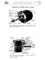
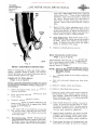
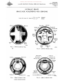
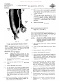
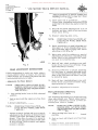
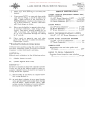
HYDROVAC POWER BRAKE SYSTEM Atmo.phere control
. line
Bleeder valve.
'Trailer brake
conoectioo plug
-----_3
End plate
'Contr~1 vah'e--_ _ _ _ _ _....:
Atmosphere i81e1 _ _ _---.,;...
From Bir deaner
vac.uum lource
Fig. I - Exterior View of Third Series ("C" Series) Single 6-3fij"
Diameter Piston Hydrovac ~o. ~7qOOO (Fig. 2 illustrates the Interior
Details of the Above Unit.)
Colllrol valve piston
. Diaphragm retlD'D spring
Bleeder valve
Outlet to wheel
.cylind;rs .
VaC1l1llllilktoD
Lubrication plug
Cylinder sheD
Fig. 2 - Sectional View of Third Series
Diameter Piston Hydrovac No. 37QOOO.
PR1NT£O IN UNITED STATES OF' AM£fUCA
A-23201
("C R Series)
•
Single 6-3/qn
Donated by John & Susan Hansen - For Personal Use Only
BRAKES
HYDROVAC POWER
Section B
Page 2
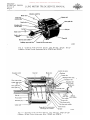
L-UNE MOTOR TRUCK SERVICE MANUAL
Atmosphere control line
Trailer brake
connection plug
""
~.'UllU"l
sheD
Piston guide tube
Atmosphere inlet _ _ _ _ _ _ _ _.....}.;;::
from air cleaner ----F.".1 plate
Bleeder u.l.,.---"\.
Outlet to wheel __--~.
cylinders
bolt
Inlet from master
A-22B1B
Fig. 3 - Exterior View of Third Series ("C" Series) Single
Diameter Guided Piston Hydrovacs H~'s. 375278 and 375279.
9-1/2"
Clamp bolt
Push rod---------rJI
Vacuum
Outlet to
wheel cylinders
piston-----:+:-l:~!!
Lubrication
plug--~~U
Cylinder shell-----.../
Vacuum inlet from vacuum source
(Inlet drawn out of position)
A-22737
Fig. ~ - Sectional View of Third Series ("C" Series) Single 9-1/2" Diameter Guided Piston Hydrovacs No's, 375278 and 375279. Donated by John & Susan Hansen - For Personal Use Only
BRAKES
HYDROVAC POWER
Section B
Page 3
L-LINE MOTOR TRUCK SERVICE MANUAL
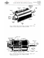
Atmosphere inlet to
fast application valve
from enaine air
deaner
valve
Atmosphere
wei
.~_'JIIII"'l:'lll!'l""
from engine
-"'~air clellDer
Lubrication
pilIP
Fig. 5 - Exterior View of Third Series ("C" Series)
Cyl inder Hydrovacs No's. 374229 and 374230.
Di~meter
BLEEDER
9-1/2 u
Tandem
9-1/2"
VALVE-"
Fig, 6 - Sectional View of Third Series ("C" Series)
Diameter Cyl inder Hydrovacs No's. 374229 and 374230.
PRINTED IN UNITED STATES OF AMERICA
Tandem
BRAKES
HYDROVAC POWER
Section B Page 4
Donated by John & Susan Hansen - For Personal Use Only
L-L1NE MOTOR TRUCK SERVICE MANUAL
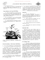
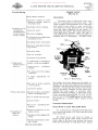
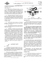
HYDROVAC POWER BRAKE SYSTEM (Bendix Hydrovacs Third Series IICI! Nos. 374000, 375278, 375279, 374229 and 374230) Hydrovac Power Brake Units (Figs. 1, 2, 3, 4, 5, 6) The hydrovac is installed on vehicles having the
conventional hydraulic brake system to make
available to the operator a greater pressure
on the hydraulic brake system than could be
exerted by foot pressure alone.
Description
The hydrovac is a hydraulic-vacuum power
braking unit which is connected to the truck or
bus braking system by a hydraulic line from
the vehicle brake master cylinder to the hydro
vac and a hydraulic line from the hydrovac to the
wheel cylinders of the vehicle brake system.
Vacuum for operation of the hydrovac is obtained
from the engine intake manifold. The hydrovac is
a self-contained unit having no external rods
or levers exposed to dirt or moisture to rust
and corrode.
Figs. 1 and 2 illustrate the single piston 6-3/4"
diameter hydrovac.
Figs. 3 and 4 illustrate the single guided piston
9-1/2" diameter hydrovac.
Figs. 5 and 6 illustrate the tandem piston 9-1/2"
diameter hydrovac.
Bleeding Instructions
must be allowed to snap back MQUICKLY"
to be released position. This rapid return of
the pedal and master cylinder piston allows
the master cylinder barrel to receive brake
fluid from the master cylinder reservoir on
the return stroke and not just draw fluid back
out of the lines when the pedal is released.
Continue bleeding until all of the air is
expelled, close bleeder valve. Repeat
bleeding operation at bleeder valve No.2,
making sure the master cylinder fluid
reservoir is kept full of brake fluid.
4. Bleed the wheel brake cylinders in any con
venient order. NOTE: Fluid withdrawn
in the bleeding operation should not be used
again.
Lubrication
It has been definitely established that lubrication
is highly important in hydrovac maintenance
and that neglectofthis service adverselya£fects
performance.
Hydrovacs shOUld be lubricated as follows:
1. Single piston 6-3/4 11 diameter hydrovacs
should be lubricated once a year (prefer
ably before cold weather) or every 20,000
miles, whichever occurs first.
2. Single piston 9-1/2 I! diameter hydrovacs
should be lubricated every six (6) months
or every 10,000 miles, whichever occurs
first. One of these lubrication periods
should occur just prior to the start of cold
weather.
Bleed the hydrovac and wheel cylinders with
the engine stopped, bleeding the hydrovac first
at the two bleeder valves (Figs. 2, 4 and 6) in
the control valve and in the slave cylinder in
the following manner:
3. The tandem piston hydrovac s should be lu
bricated once a year (preferably before
cold weather) or every 20,000 miles, which
ever occurs first.
1. Attach bleeder tube to bleeder valve No.1
by pushing the end of ·tube over the bleeder
valve.
The lubrication service should be performed
with the hydrovac mounted on the vehicle, with
the engine stopped, and brakes released.
2. Insert the end of bleeder tube in a con
tainer containing a small amount of brake
fluid.
Single piston hydrovacs have one pipe plug in the
cylinder shell (Figures 2 and 4), remove pipe
plug and fill cylinder with vacuum cylinder oil
to the level of the bottom of the hole. Replace
pipe plug. Tandem piston hydrovacs have two
pipe plugs, one in the end plate below control
valve and the other in the center plate between
the vacuum cylinders (Fig. 5). Remove pipe
plugs and fill cylinder with vacuum cylinder
oil to the level of the bottom of the holes. Re
place pipe plugs.
3. Unscrew the ble'Cder valve 3/4 turn and
depress brake pedal by hand. Allow the
pedal to return quickly to the MOFF"
position.
NOTE: Bleeding instructions for all vehicles
having the residual check valve located in the
master cylinder recommend allowing the
brake pedal to return to the "OFF" position
slowly. However, in brake systems where
the residual check valve is located in the
hydrovac slave cylinder end the brake pedal
NOTE: The quantities of oil required are
automatically controlled by the position of
pipe plugs. They are located so as to es
tablish the proper oil level.
Donated by John & Susan Hansen - For Personal Use Only
L-LlNE MOTOR TRUCK SERVICE MANUAL
BRAKES
HYDROVAC POWER
Section B
Page 5
HYDROVAC OIL CAPACITIES ARE AS FOLLOWS:
APPROXIMA TE OIL CAPACITY
!
HYDROVAC SIZE
END CHAMBER
CENTER CHAMBER
6-3/4 11 Diam.
Single Piston
I ounce
None
9-1/211 Diam.
Single Piston
2 ounces
None
9-112" Diam.
Tandem Piston
2 ounces
4 ounces
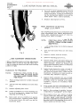
Hydrovac Air Inlet Filter (Fig. 7).
On all hydrovac installations, a filter is pro
vided to clean the air entering the power chamber
whenever the brakes are applied. This filter
is located on the inside of cab below driver's
seat. The air cleaner should be inspected every
1000 miles. If air passages are restricted, re
move the air cleaner, dismantle and thoroughly
clean all parts in a cleaning solvent and allow
to drip dry. Then saturate the air cleaning
elelTI.ent with a light oil, reassemble and install
on vehicle.
NOTE: Where the air inlet line is connected
to the engine air filter, servicing the air filter
as outlined in the Fuel System Maintenance
Section will suffice,
Hair filter
element
Screen
Fig. 7 - Hydrovac"Air Inlet Fi Iter.
CAUTION: All hose connections lTI.ust be secure
and leak-proof.
Vacuum Line Oil Bath Air Cleaner (Fig. 8).
On trucks having a separate air cleaner for
the vacuum line, this unit is located on the engine
side of cowl at upper right hand corner. The
vacuum line air cleaner prevents any dirt or
foreign lTI.atter being drawn into intake manifold
when the brakes are applied. In normal operation,
service the cleaner every 5000 miles by re
moving oil reservoir, cleaning thoroughly in a
suitable cleaning solution or kerosene and re
filling with clean engine oil to indicated level
on side of reservoir (Fig. 8). Use same grade of
oil as used in engine crankcase.
CAUTION: Be sure that reservoir seats per
fectly against gasket and that clamp is correctly
installed after completing service operation.
Should a leak occur, the engine performance and
hydrovac operation will be seriously affected.
Vacuum Connection Service
Rernove the vacuum connection elbow from the
intake manifold every 10,000 miles and in
spect the elbow and vacuum line for any possible
obstruction. Clean the elbow and reinstall.
PRINTED IN UNITED STATES OF AMERICA
Fig. 8 - Vacuum Line Oil Bath Air Cleaner.
Donated by John & Susan Hansen - For Personal Use Only
BRAKES
HYDROVAC POWER
Section B
Page 6
L-UNE MOTOR TRUCK SERVICE MANUAL
BRAKE TROUBLE CHART FOR VEHICLES EQUIPPED WITH HYDROVAC UNITS
TRUCK BRAKE TROUBLES ARE EASILY DIAGNOSED
IF THE COMPLAINT IS UNDERSTOOD.
THEY WILL ALWAYS SHOW UP IN ONE OR MORE
OF THE FOUR WAYS LISTED BELOW.
THE DRIVER MAY REPORT OTHER SYMPTOMS, BUT
THESE WILL NOT HELP IN YOUR ANALYSIS.
BE SURE TO HAVE THE DRIVER TELL YOU WHICH
OF THESE FOUR CONDITIONS HE HAS NOTICED.
IF AT ALL POSSIBLE; DRIVE THE TRUCK AND ACTU
ALLY FEEL THE CONDITION.
THE "FOUR WAYS" OR CONDITIONS No.1 Hard Pedal No. 2 IIGrabby" Brakes POSSIBLE SOURCE OF TROUBLE
1- Vacuum failure due to:
(a) Faulty vacuum check valve.
(b) Collapsed vacuum hose.
(c) Plugged vacuum fittings.
2-Bound-up pedal shaft.
3-Glazed linings.
4-Grease or brake fluid on linings.
5-Hydrovac trouble.
I-Grease or brake fluid on linings. 2-Scored drums. 3-Anchor pins bound-up. 4-Hydrovac valve trouble. I-Brakes need adjustment.
2-Air in hydraulic system.
No.3 3 -Hydraulic leak.
4-Master cylinder fluid - reservoir needs replen
Pedal Goe s to Floor
ishing.
or almost to floor
5-Cracked drum.
6-Hydrovac leakage.
No.4
Brakes Fail
to Release
I-Master cylinder compensating - post covered or
plugged.
2-Anchor pins bound-up.
3-Bound-up brake pedal shaft.
4-Brakes improperly adjusted.
5-Faulty hydraulic check valve - at master cylinder
or hydrovac.
6-Hydrovac valve or ball check trouble.
I
Donated by John & Susan Hansen - For Personal Use Only
L-UNE MOTOR TRUCK SERVICE MANUAL
Hydrovac Check
The following data will assist in the check
ing of brake systems utilizing the Hydrovac
Power Unit. The unit should be checked on the
vehicle to determine that the trouble is not
elsewhere in the brake system. The various
units of the brake system should be checked
individually for damage or misadjustment be
fore proceeding with the hydrovac check.
A good quick way to check the hydrovac, to
determine whether it is operating at all, is as
follows:
1. With the vehicle parking brake applied,
clutch released, and trarlsmission in neu
tral position; press the brake pedal to about
a medium brake application and hold.
2. Turn the ignition switch to "ON" and start
the engine.
3. Sho rtly afte r the engine starts. the brake
pedal pressure will be felt to relieve it
self. This is caused by the Hydrovac pick
ing up the brake application. The relief
or movement is quite noticeable when the
hydrovac is functioning properly.
If no movement or relief is felt at the brake
pedal when making the above check, it is good
practice to check the brake system further be
fore centering attention on the hydrovac unit.
Check as follows:
1. Master Cylinder Piston Rod Clearance:
Make certain linkage is properly adjusted
to permit opening of compensating port
with brake pedal in normal full released
position. Failure to properly uncover the
compensating port may cause sufficient
pressure to be maintained in the brake
system to hold the hydrovac valve in a
partially applied position and thus cause
dragging brakes.
2. Restricted Vacuum Lines:
Check for vacuum at the hydrovac by dis
connecting the vacuum line at the hydrovac
vacuum connection fitting and holding a
thumb over the line, with the engine run
ning. If no vacuum exists, or if air flow
is slow, check vacuum line to manifold for
kinks in tUbing and collapsed liners in
hoses. Also test the check valve to be sure
it opens. Check fitting at engine manifold
for restriction.
3. Restricted Air Line and Air Cleaner:
Disconnect the air cleaner line at the hy
drovac and blow into the line. If the line
is restricted, check for collapsed hose or
tubing. Clean or replace air cleaner.
PRJNTED IN UNITED STATES OF" AMERICA
BRAKES
HYDROVAC POWER
Section B
Page 7
4. Brakes:
Check brake shoe adjustment for proper
clearances. Excessive shoe clearance will
cause loss of pedal reserve travel. Insuf
ficient shoe clearance may cause dragging
brakes.
Donated by John & Susan Hansen - For Personal Use Only
Donated by John & Susan Hansen - For Personal Use Only
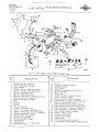
L-LINE MOTOR TRUCK SERVICE MANUAL
BRAKES
AIR
Section C
Page 1
AIR BRAKES
(For Description and Operation see Shop Talk No. 24)
AIR BRAKE EQUIPMENT
Air brake equipznent on trucks and truck
tractors provides a zneans of controlling the
brakes through the znediuzn of coznpressed air.
Air brake equipznent consists of a group of
devices. Sozne znaintain a supply of coznpressed
air, sozne direct and control the flow of the
coznpressed air, and others transforzn the en
ergy of coznpressed air into the znechanical
forceandznotionnecessary to apply the brakes.
Different types and sizes of devices are used
on different types of vehicles to zneet the oper
ating requireznents, but they are all fundaznen
tally the sazne.
Following are the devices
coznprising a typical truck or truck-tractor air
brake systezn, with a brief description of the
function of each device.
Compressor
The coznpressor supplies the coznpressed
air to operate the brakes.
Slack Adjusters
Slack adjusters provide a quick and easy
znethod of adjusting the brakes to coznpensate
for brake lining wear. One slack adjuster is
used for the brakes on each wheel.
Cocks
Cut-out cocks are used in the trailer con
nection lines to perznit these lines to be closed
when they are not being used. Reservoir drain
cocks are used also, znounted at the bottozn of
the reservoir. The drain cocks perznit drain
ing the oil and water which collects in the res
ervoir.
Tubing and Tubing Fittings
Tubing and tubing fittings connect the
different air brake devices in the air brake
systezn.
Governor
The governor controls the coznpression of
air by the coznpressor. Although the coznpres
sor runs continuously when the engine is run
ning, the governor, acting in conjunction with
the unloading znechaniszn in the coznpressor
cylinder head, stops and starts the coznpression
of air by the coznpressor when the desired znax
iznuzn and zniniznuzn air pressures are present
in the air brakesystezn.
Brake Valve
The brake valve controls the air pressure
being delivered to the brake chaznbers and in
this way controls the operation of the brakes.
Hose, Hose Fittings, Hose Couplings and
Dummy Couplings
Flexible hose lines and hose fittings are
used where it is necessary to have an air line
between two points of the vehicle which change
their position in relation to one another. Hose
lines also znake connections between two ve
hicles, and in such cases they are provided with
hose couplings to perznit the connections to be
easily connected or disconnected.
DUITIITIY
couplings seal the hose coupling s against the
entrance of dirt when the hose couplings are
not in use. DUITIITIY couplings on the back of
tractor cabs also provide a place for attaching
the free ends of connecting hose that is not,
being used.
Quick Release Valve
The quick release valve speeds the release
of air pressure frozn the front wheel brake
chaznbers.
Safety Valve
The safety valve protects the air brake
systezn against excessive air pressure.
Relay Valve
Reservoirs
The relay valve speeds the application and
release of air pressure frozn the rear wheel
brake chaznbers.
Brake Chambers and Brake Cylinders
Brake chaznbers and brake cylinders trans
forzn the ener gy of coznpres sed air into the zne
chanical force andznotionnecessary to apply the
brakes. One brake chaznber or one brake cylin
der is used to operate the brakes on each wheel.
PRINTED IN UNITEO STAT·ES OF AMER!CA
Reservoirs store the coznpressed air until
it is needed for brake operation and provide
sufficient air pressure to znake several brake
applications even after the engine has stopped.
Air Gage
The air gage znounted on the instruznent
panel of the vehicle registers the pressure in
the ai r brake systezn.
Donated by John & Susan Hansen - For Personal Use Only
BRAKES
AIR
Section C
Page 2
L-UNE MOTOR TRUCK SERVICE MANUAL
Air Supply Valve
In some cases the air supply valve is in
cluded to provide an easy means of obtaining
compressed air from the air brake system for
such purposes as tire inflation.
Low Pressure Indicator
The low pressure indicator is often pro
vided to warn the driver by sounding a buzzer
or by lighting a warning light if for any reason
the air pressure in the air brake system falls
below a safe operating point.
Stop Light Switch
The air operated stop light switch provides
a simple means of controlling the stop lights of
the vehicle.
Air Horn
On some vehicles the air horn is included
to provide an effective warning signal.
Alcohol Evaporator
On some vehicles the alcohol evaporator
is included to prevent moisture freezing in the
air brake system.
OPERATION OF THE AIR BRAKE EQUIPMENT In the case of the relay valve (6-wheel
models), the connections lead to tee connections
and from there to each of the four rear brake
chambers.
When the pressure built up in the brake
chambers and acting against the brake valve
diaphragm is enough to compress the regulat
ing spring, the diaphragm moves upward, allow
ing the inlet valve to close by action of its
spring.
The exhaust valve remains closed by action
of the inlet valve spring and tilting of the rock
er arm. Further increase of brake chamber
pressure is thus prevented. If, however, there
should be leakage from the brake chambers or
piping, while the brake valve lever remains in
this position, the resulting drop in pressure
under the brake valve diaphragm will cause the
regulating spring to again unseat the inlet valve
and restore the lost pressure.
Release
When the foot is removed from the brake
pedal, the brake valve lever is moved back
toward normal position again, which relieves
the tension on the regulating spring so that the
diaphragm will be moved upward to its normal
position by brake chamber pressure under
neath it. This permits the exhaust valve to be
unseated by its spring which opens brake cham
ber line to atmosphere and allows air to ex
haust from the brake chambers.
Charging
The reservoirs are charged with air by the
compressor. The reservoir air has access to
the inlet valve chamber of the brake valve and
the inlet valve is then held closed by the tension
of its spring and air pressure.
Service Application
When it is desired to apply the brakes, foot
pressure is applied to the brake pedal, which
action is carried through the brake rod pulling
up on the lever of the brake valve. This com
presses the spring, deflects the diaphragm
downward, and through the medium of the rock
er arm closes the exhaust valve and opens the
inlet valve. Air is thereby admitted from the
reservoir to the brake valve, thence out the two
side outlets to the front and rear brake cham
bers. The power thus exerted against the brake
chamber diaphragms or pistons forces the push
rods out, rotating the camshafts to apply the
brakes.
In flowing to the rear brake chambers the
air pressure passes through the quick release
valve ente ring at the top, deflecting the dia
phragm and its seat to seal the exhaust open
ing while the air pressure passes around the
diaphragm to the two side connections, each
leading to a brake chamber.
If the brake valve lever is moved all the
way back to normal position and left there (foot
entirely removed from brake pedal), the brakes
will entirely release, but if moved only part
way back (foot pressure eased), the brakes will
only partially release, Le., the exhaust valve
will remain open until the brake chamber pres
sure has reduced to such an amount as will no
longer hold the diaphragm up, whereupon the
regulating spring will move the diaphragm,
with rocker arm, downward again and close the
exhaust valve.
The brake chamber line to the rear wheels
is released only up to the quick release valve or
relay valve. This allows the diaphragm to un
seat, uncovering the exhaustportthrough which
the rear brake chambers are then exhausted.
OPERATING INSTRUCTIONS
Operating the brakes of an air-braked ve
hicle differs very little from operating the
brakes of a passenger car. Because operation
of the brake pedal requires very little physical
effort, proper control of the brakes is easily
accomplished.
Donated by John & Susan Hansen - For Personal Use Only
BRAKES
AIR
Section C
Page 3
L-UNE MOTOR TRUCK SERVICE MANUAL
COMPRESSOR (TYPE U) The distance the brake pedal is depressed
determines the amount of air pressure deliv
ered to the brake chambers, and the brake
chamber pressure determines the braking
force. Thus the driver may definitely control
the brakes of the vehicle by keeping in mind
the fact that he is operating a brake valve
capable of giving finely graduated brake con
trol and making full use of this feature.
An air-braked vehicle should not be moved
unless the air gage shows at least 60 pounds
air pressure in the air brake system, because
the brakes are not fully effective at lower
pressures.
While operating the vehicle, the
driver should periodically observe the air
pressure registered by the dash gage, to be
sure it is being maintained properly. If the air
pressure drops to a low point, or if the warn
ing buzzer or light signifies the pressure is
low, the vehicle should be stopped and the
trouble corrected.
The best stop results when the brake ap
plication is as hardat firstas the speed, condi
tion of the road, and passenger comfort permits,
and then graduated off as the speed decreases.
As the stop is completed, there should be only
sufficient air pressure in the brake chambers
to hold the vehicle stationary. The brakes must
never be applied lightly at first and the braking
pressure increased as the speed decreases, as
this will result in a very rough stop.
The brake pedal should not be "fanned," as
this merely wastes compressed air and has no
bearing on correct br.aking results.
The brake pedal should not be fully de
pressed except in cases of emergency as this
causes full braking force to be delivered to the
wheels and this should not be necessary in
ordinary service.
Normally the engine is used to assist the
brakes by not disengaging the clutch until the
engine reaches idling speed.
In the event a trailer breaks away from a
truck or tractor, the driver must immediately
apply the brakes and bring the truck or tractor
to a stop. Then the truck or tractor should be
held with the hand brake while the cut-out cocks
in the emergency and service lines are closed.
The truck or tractor air brake system will then
be recharged to normal pressure.
When disconnecting trailers from trucks or
tractors, the emergency feature of the air brake
system on the trailer is often used to lock the
trailer brakes. This is approved practice but
the air brake system mustnotbe depended upon
to hold a vehicle parked. The parking brake
must always be applied or the wheels blocked.
PRINTED IN UNIT£O STATES OF AMERICA
Fig. I - Air Compressor Installed.
IDENTIFICATION. All Bendix - Westing
house compressors are identified by the number
stamped on the name plate riveted to the side
of the crankcase. Name plates also show the
serial number and type of the compressor but
compressors cannot be identified by the serial
number or the type designation.
The type designation shown on the name
plate is in accordance with the following:
Type
Number
Rated
Luof
of
CaCom- briCylinpaccation
ders !presity
sor
2 or 3
U
Type
of
Mount
ing
Type
of
Cooling
Eng.- 4,6, Flange-F Air-A
E or 7-114 Horiz. -H Water-W
self-S orl2 Verti
cal-V
Thus a 2 UE 7-1/4 VW compressor is a two
cylinder, type U, engine-lubricated compressor
with a displacement of 7-114 cubic feet per
minute at 1250 r.p.m., vertically mounted and
water-cooled.
PREVENTIVE MAINTENANCE AND TROUBLE SHOOTING Daily Service
(a) International trucks are
usually
equipped with the engine lubricated type air
compressor, however, if the compressor is of
the self-lub ricated type, check the oil level in
the compressor crankcase and replenish if nec
essary.
Donated by John & Susan Hansen - For Personal Use Only
BRAKES
AIR
Section C
Page 4
L-LINE MOTOR TRUCK SERVICE MANUAL
(b) Should it be nec e s sa ry to d rain the
engine cooling systeITl to prevent freezing, al
ways drain the cOITlpressor cylinder head (see
Fig. I).
(d) ReITlove cOITlpressor discharge valve
cap nuts and check for presence of excessive
carbon. If excessive carbon is found, clean the
COITlpressor cylinder head; also check COITl
pressor discharge line for carbon and clean or
replace the discharge line if necessary.
Every Month or After Each 2,000 Miles
(a) Service cOITlpressor air strainer. Re
ITlove and wash all parts including curled hair
in cleaning solvent. Saturate curled hair with
clean engine oil and squeeze dry before re
placing it in the strainer.
(b) If COITlpressor is the self-lubricated
type, drain and flush COITlpressor crankcase
and refill with clean engine oil.
(c) Check cOITlpressor ITlounting and drive
for alignITlent, belt tension, etc. Adjust if nec
essary.
Inspection
1.
Be sure cOITlpressor air strainer is
clean and properly installed. Also be sure
blanking covers and gaskets are installed on
all strainer openings not being used in the COITl
pressor intake ITlanifold.
z. With cOITlpressor running, check for
noisy operation and oil or water leaks.
3.
Check unloader valve clearance.
4.
Check cOITlpre ssor drive for alignITlent,
belt tension, etc.
5.
Check to be sure cOITlpressor ITlounting
bolts are secure.
Operating Tests
DISCHARGE PORT Fig. 2 - Adjusting Compressor Unloading Valve
Clearance.
Every Six Months or After Each 10,000 Miles
(a) If the cOITlpressor is lubricated froITl
the engine, dean oil supply line to cOITlpressor.
(b) Check cOITlpressor unloading valve
clearance and adjust if necessary (Fig. Z).
Clearance ITlust be 0.010 inch ITliniITluITl to
0.015 inch ITlaxiITluITl. To adjust clearance,
loosen lock nuts and turn adjusting screws until
proper clearance is obtained. Then tighten
lock nuts. Clearance can be checked only when
governor is cut in (coITlpressor not unloaded).
Check unloading valve lever for binding.
(c) If cOITlpressor is the self-lubricated
type, service crankcase breather. Wash breath
er in cleaning solvent.
Because of the ITlany different types of
air brake systeITls found on different types of
vehicles, it is difficult to set up any specific
series of tests to deterITline the serviceability
of a COITlpressor on a vehicle. Failure of the
cOITlpressor to ITlaintain norITlal air pressure
in the air brake systeITl of a vehicle usually
denotes loss in efficiency due to wear, provided
leakage in the reITlainder of the systeITl is not
excessive. Another sign of wear is excessive
oil passing. lfeitherof these conditions develop
and inspection shows the reITlainder of the air
brake equipITlent to be in good condition, the
cOITlpressor ITlust be repaired or replaced.
Air Leakage Tests
1.
Excessive leakage past the discharge
valves can be detected by fully charging the air
brake systeITl and then with the engine stopped,
carefully listening at the COITlpressor for the
sound of escaping air. This ITlust be done in a
quiet place and if air pressure can be heard
escaping inside the COITlpressor, the discharge
valve leakage is excessive, and the cOITlpressor
cylinder head or the cOITlplete COITlpressor ITlust
be replaced.
Z.
With the airbrake systeITlfully charged
(governor cut out) coat the unloading box cover
with soapsuds to check for leakage past the
unloading diaphragITls. Leakage of a one-inch
soap bubble in three seconds is perITlissible.
If excessive leakage is found, the cOITlpressor
cylinder head or cOITlplete cOITlpressor should
be repaired or replaced.
Donated by John & Susan Hansen - For Personal Use Only
L-UNE MOTOR TRUCK SERVICE MANUAL
BRAKES
AIR
Section C
5
BRAKE VALVE
Trouble Shooting
(See Fig. 3)
Dirty intake strainer.
Description
Excessive carbon in com.
pressor cylinder head or
discharge line.
The brake valve is fitted with a lever suit
able for connecting to the brake pedal. The
pedal controls the m.ovem.ent of an inlet valve
and exhaust valve which in turn controls the
air pressure being delivered to or released
from. the brake cham.bers on the vehicle. To
fully apply the brakes, the brake pedal m.ust be
fully depressed; whereas when the pedal is
only partially depressed, correspondingly less
braking force is developed.
In other words,
valves leaking.
Di
Com.pressor fails
to m.aintain
Excessive wear.
adequate pres
sure in the air
Drive belt slipping.
brake system..
No clearance at com.pressor
unloading valves.
Unloading valves stuck open.
Excessive leakage of unload
ing valves.
Boot-·-_ _:a..
Excessive wear. Dirty air strainer. Excessive oil pressure. Com.pressor
passes exces
sive oil.
Oil return line or passage to crankcase plugged.
Com.pressor
flooded.
crankcase
from. engine
Air inlet from. ~.~. . . .
reservoir ~
Oil rings
stalled.
im.properly
in
Fig. 3 - Brake Valve.
Back lash in drive coupling
or drive gears.
Loose drive pulley.
Noisy operation.
Excessive carbon in cylinder
head or discharge line.
Worn or burnt-out bearings.
Excessive wear.
De f e c t i v e
unloading dia-
the farther the driver depresses the pedal, the
greater the air pressure delivered to the brake
cham.bers and the m.ore effective the brake ap
plication. At any tim.e the brakes of the vehicle
m.ay be partially released by the driver per
m.itting the, brake pedal to partially return
towards released position or they m.ay be en
tirely released by perm.itting the pedal to re
turn to full released position. In this m.anner
the am.ount of force being applied to the brakes
of the vehicle is always under control of the
driver.
Preventive Maintenance
Every Month or After Each 2,000 Miles
Com.pressor
does not
unload.
Excessive clearance at un
loading valves.
Unloading cavity plugged with
carbon.
Unloading m.echanism. bind
ing or stuck.
PRINTE:O IN UNfT!::O STATES OF' "MERICA
(a) Lubricate all linkage between the brake
valve and brake pedal; also lubricate the brake
valve lever pin.
(b) Check to be sure that no strain is
placed on the brake valve lever, because the
lower edge of the lever cap strikes the cover
when the brake pedal is fully depressed. Adjust
Donated by John & Susan Hansen - For Personal Use Only
BRAKES
AIR
Section C
Page 6
L-L1NE MOTOR TRUCK SERVICE MANUAL
pedal stop or linkage, if necessary, to prevent
this interference. After any adjustment, check
brake valve delivery pressure.
(c) Be sure the brake valve lever strikes
the cover of the valve' when the brake pedal is
in released position. If necessary, adjust pedal
rod length.
Lever pin
2.
Hold brake pedal at several different
positions between release position and fully de
pressed position and observe that intermediate
delivered pressures between five and seventy
pounds aredefinitelydeterminedby the position
in which the brake pedal is held.
Leakage Tests
l.
With brakes released, coat the exhaust
port with soapsuds.
...-. --.,..
2.
With brakes fully applied, coat the ex
haust port with soapsuds.
3.
Leakage in excess of a one-inch soap
bubble in one second is not permis sible in either
of these tests. If excessive leakage is found,
the brake valve must be repaired or replaced.
4.
With brakes applied check for leakage
out the top of the brake valve. No leakage is
permissible. If leakage is found, the brake
valve must be replaced.
Diaphragm _ . _ - j 7 i
Return spring ---RH~a~;t
Seal---ti~m~aJi!.~
BRAKE VALVE (Hand Operated) Type HP Seal-----
Description
A.22837
Fig.
~
- Sectional View Of Brake Valve.
Testing For Serviceability Operating Tests 1.
Check the delivery pressure of the
brake valve using an accurate airpressure test
gage. On vehicles having trailer connections
the test gage may be conveniently connected to
the service line outlet at the rear of the ve
hicle. Note that the first movement of the brake
pedal towards applied position, after the slack
is taken up, causes the brake valve to deliver
approximately five pounds air pressure. Note
that approximately full reservoir pressure is
delivered by the brake valv~ when the brake
pedal is fully depressed.
If the brake valve
does not deliver approximately full reservoir
pressure, when the brake pedal is fully de
pressed, adjust the pesal stop or linkage so as
to increase the travel of the brake valve lever.
This should increase the delivered pressure.
On some vehicles the pedal stop is so arranged
as to prevent the brake valve from delivering
full reservoir pressure.
This arrangement
must not be altered on such vehicles unless a
higher delivery pressure is desired in order to
increase the effectiveness of the brakes. When
making this adjustment, be sure no strain is
placed on the valve lever due to the edge of the
lever cap striking the cover when the brake
pedal is fully depressed. Also be sure the brake
valve lever returns to full release position when
the brake pedal is released.
Type HP brake valves (Fig. 5) are used for
controlling the brakes on a trailer independent
ly of the brakes on the towing vehicle. They
are usually mounted on the steering column or
on the dash and the driver may put the handle
in anyone of several positions between brakes
released and brakes fully applied position so
the brakes on the trailer are kept applied until
the brake valve handle is returned to release
position. The distance the brake valve handle
is moved in a clockwise direction toward ap
plied position determines the severity of the
brake application. The driver may, therefore,
control the brakes on the trailer as the speed,
load, and road conditions require.
..
m=====~
__
-------HANDLE
fRIGION LOCK
.:!~~iliiiii~-.L.._~_ EXHAUST
VALVE
riliicr-+----INlET VALVE
==-__
INLET PORT
Fig. 5 - Sectional View Of Hand Brake Value.
Donated by John & Susan Hansen - For Personal Use Only
L-LINE MOTOR TRUCK SERVICE MANUAL
Testing for Serviceability (Hand Brake Valve)
BRAKES
AIR
Section C
Page 7
INLET PORT
Operating Tests
1.
Check the delivery pressure of the
brake valve using an accurate air pressure test
gage. The test gage may be conveniently con
nected to the service line outlet at the rear of
the vehicle. With the brake valve handle moved
to its fully applied position, the brake valve
must deliver at least sixty pounds pressure.
2.
Move the brake valve handle to several
different positions between fully applied and
fully released positions and observe that the
air pressure registered by the test gage varies
in accordance with the position to which the
handle is moved.
BRAKE
BRAKE
CHAMBER
CHAMBER
PORT
PORT
Fig. 6 - Sectional View Of Quick Release Valve.
Operating Tests
Leakage Tests
1.
With brake valve handle in released
position. coat the exhaust port with soap suds
to check for leakage.
2.
With brake valve handle in fully applied
position, coat the exhaust port with so,ap suds to
check for leakage.
3.
Leakage in excess of a one inch soap
bubble in one second is not permissible in either
of these tests. If excessive leakage is found it
will usually be caused by dirty or worn valves
or valve seats and the inlet and exhaust valve
assembly or the complete brake valve must be
repaired or replaced.
Leakage due to dirty
valves and valve seats may be corrected by
removing the inlet and exhaust valve assembly
and cleaning the valves and valve seats. Leak
age due to worn valves maybe corrected by in
stalling a new inlet and exhaust valve assembly.
If the valve seats are pitted or worn excessive
ly or if the installation of a new inlet and ex
haust valve assembly does not correct the
leakage, the brake valve must be repaired or
replaced.
QUICK RELEASE VALVE
Description
The purpose of the quick release valve is to
reduce the time required to release the brakes
by hastening the exhaust of air pressure from
the brake chambers. It is most commonly used
with front wheel brake chambers.
The valve consists of a body containing a
spring loaded diaphragm so arranged as to per
mit air pressure to flow through the valve in
one direction; but when the supply pressure is
reduced, the air which has passed through the
valve is permitted to escape through the ex
haust port (Fig. 6).
J>AINTEO IN UNITED $T.t.T£S Of' AMERICA
Apply the brakes and observe that when the
brakes are released, air pressure is quickly
exhausted through the exhaust port of the valve.
Be sure the exhaust port is not restricted in
any way.
The valve must be tested at regular inter
vals for leakage by applying soapsuds on the
exhaust port with the brakes applied. On re
leasing the brakes see that the valve releases
immediately with the corresponding return
movement of the foot pedal. Leakage may be
caused by dirt in the valve or a defective dia
phragm. As a rule the diaphragm should be
replaced at least once every year.
The air line from the brake valve to the
rear wheel chambers is released back to the
quick release valve. This allows the .diaphragm
in the quick release valve to unseat, uncovering
the exhaust port in the valve and permitting the
air in the brake chambers to escape quickly at
the quick release valve.
On some trucks air is released from the
front wheel brake chambers back through the
lines to the foot brake valve and exhausted at
that point. Where this is the case, the quick
release valve housing installed at the front of
the vehicle serves merely as a connector and
does not contain either a diaphragm or dia
phragm spring and the exhaust opening in the
quick release valve housing is closed with a
plug.
IMPORTANT:
DO NOT REMOVE' THIS
PLUG, TO DO SO WILL RENDER THE FRONT
WHEEL BRAKES INOPERATIVE.
Leakage Tests
1.
With brakes released, coat the exhaust
port with soapsuds to determine leakage.
2.
With the brakes fully applied, coat the
exhaust port with soapsuds to determine leak
age.
Donated by John & Susan Hansen - For Personal Use Only
BRAKES
AIR
Section C
Page 8
L-LINE MOTOR TRUCK SERVICE MANUAL
3.
Leakage in excess of a one-inch. soap
bubble in one second is not permissible in either
of these tests. If excessive leakage is found,
the relay valve must be repaired or replaced.
in pressure and raises, lowers, or completely
exhausts the air pressure in the rear brake
chambers as the brake valve raises, lowers,
or completely exhausts air pressure from it.
DOUBLE CHECK VALVE
'BRAKE VALvE PORT
Description
A double check valve is used on the tractor
truck at the frame side rail (Fig. 7). It is con
nected into the air lines from the relay valve
to the trailer lines. The purpose of the double
check valve is to control the brakes on the
trailer or towed load. If the double check valve
were not used when one of the brake valves was
moved to its applied position, air pressure
from the reservoir would escape through the
exhaust port of the other brake valve, whose
exhaust valve would be open. When the double
check valve is used and one of the brake valves
is moved to the applied position, the double
check valve blocks off the line leading to the
other brake valve, in this manner preventing
any loss of air pressure through the open ex
haust valve of the brake valve not being oper
ated.
:~~i~~~f~ ~~!l DIAPHRAGM
DIAPHRAGM GUIDE
g..==-;---BY.PASS PORi
GUIDE RING
EXHAUST PORi
SUPPLY VALVE
RESERVOIR PORT -----+-!!~~~
1.·9357
Fig. 8 - Sectional View Of Relay Valve.
Testing for Serviceability
Operating Tests
1.
With the air brake system charged,
apply brakes and check to be sure the rear
wheel brakes controlled by the relay valve ap
ply promptly.
2.
Release brakes and check to be sure
air pressure is exhausted from the exhaust
port of the relay valve promptly.
Leakage Tests
OUTLEI
Fig. 7 - Sectional View Of Double Check Valve.
Testing
With the brake system fully charged and
both brake valves in released position, move
one of the brake valves to applied position, and
check with soapsuds for leakage at the exhaust
port of the brake valve not being operated. Re
peat test with the other brake valve. Leakage
in excess of a 3-inch soap bubble in 3 seconds
is not permissible. If excessive leakage is
found, the defective double check valve must
be replaced.
RELAY VALVE
Description
The relay valve (Fig. 8)
up the ap
plication and release of the rear wheel brakes.
It is controlled by the brake valve and keeps
the air pressure in the rear brake chambers
the same as the pressure being delivered by the
brake valve. It reacts to even slight changes
1.
With brakes released, coat the exhaust
port with soapsuds to determine leakage.
2.
With brakes fully applied, coat the ex
haust port with soapsuds to determine leakage.
3.
Leakage in excess of a one-inch soap
bubble in one second- is not permissible in either
of these tests. If excessive leakage is found, the
relay valve must be repaired or
GOVERNOR (TYPE 0-1)
Description
The purpose of the compressor governor
is to automatically control the air pressure
being maintained in the reservoirs of the air
brake system by the compressor, between the
maximum pressure desired (100-105 Ibs.) and
the minimum pressu.re required for safe brake
operation (80-851bs.). To understand this func
tion of the governor, it should be remembered
that while the compressor may run continuous
ly, actual compression of air is controlled by
the governor, which, acting in conjunction with
the compres sor unloading mechanism,
or
starts compression when these maximum and
minimum reservoir pressures are reached.
Donated by John & Susan Hansen - For Personal Use Only
L-LINE MOTOR TRUCK SERVICE MANUAL
TUBE
ADJUSTING SCREW BRACKET
UPPER VAtVE GUIDE
TO COMPRESSOR
UNLOADING
MECHANISM
STRAINER
lOWER VALVE SPRING
fROM RESERVOIR
A-9J66
Fig. 9 - Sectional View Of Governor.
The design of the compressor governor is
based on the principle of a Bourdon tube which
is a flattened metal tube bent to a curve that
tends to straighten under internal pressure
(Fig. 9). This reaction by the tube, due to
changes in the air pressure in the tube, in
creases or decreases the spring load on the
valve mechanism of the governor and makes
the valve mechanism assume its "cut-in" or
II cut outll positions in accordance with the air
pressure in the reservoir. Two types of gover
nor cases will be found in service, one being a
die cast case and the other a pressed steel
case. Both types of cases are interchangeable
with each other and the working parts of the
governor used in both types of cases are iden
ticaL
Preventive Maintenance
Every Six Months or After Each 10,000 Miles
Remove the governor air strainer and wash
all parts in cleaning solvent. L,amb IS wool in
the air cleaner may be used again if it can be
washed thoroughly clean in cleaning solvent,
otherwise it must be replaced.
Every Year Or After Each 25,000 Miles
(a)
parts.
.BRAKES
AIR
Section C
Page 9
Z.
With engine running, slowly reduce
the air pressure in the air brake system by
applying and releasing the brakes and observe
at what pressure registered by the dash gage
the governor cuts in and compression is re
sumed. The governor must cut in between 80
and 85 pounds.
3.
Before condemning or adjusting the
pressure settings of the governor, be sure the
dash gage is registering accurately. This may
be done by using an accurate test gage to check
the pressure registered by the dash gage.
4.
When necessary, the pressure settings
(cut-in and cut-out pressures) may be adjusted
after removing the cover. The pressure set
tings are raised by loosening the adjusting
screw lock nut and turning the adjusting screw
clockwise viewed from the top (Fig. 9). Pres
sure settings may be lowered by turning the
adjusting screw counterclockwise. The lock
nut must be tightened after any adjustment.
5.
If the governor cannot be adjusted to
cut-in and cut-out at the proper pressure set
tings, it should be replaced.
6. Adjustment of the range between the
cut-in and cut-out pressure is made by remov
ing shims beneath the upper valve guide (Fig.
9) to increase the range or by installing addi
tional shims to dec rease the range.
Leakage Tests
1.
Remove cover and with the governor
in its cut-out position, test for leakage by ap
plying soapsuds to the exhaust port.
Z.
With the governor in its cut-in position
test for leakage by applying soap suds to the
exhaust port.
3.
Leakage in excess of a one-inch soap
bubble in three seconds is not permissible in
either of the above tests. If excess leakage is
found. the governor must be replaced.
4.
Install cover after making tests.
Disassemble governor and clean all
SAFETY VALVE
(b) Cleanorreplaceboth tubing lines con
necte'd to the governor.
Testing for Serviceability and Adjusting
Operating Tests
1.
With the engine running, build up air
pressure in the air brake system and observe.
at what pressure registered by the dash gage
the governor cuts out stopping further com
pression. The governor must cut out between
100 and 105 pounds.
PRINTED IN UNITED STATES OF AMERICA
Description
1.
The purpose of the safety valve is to
protect the air brake system against excessive
air pressure. Should the air pressure in the
air brake system rise above the setting of the
safety valve at 150 pounds. the valve opens and
permits pressure above 150 pounds to be ex
hausted. It is located on one of the reservoirs.
Z.
The safety valve consists of a spring
loaded ball check valve which is set to "blow
offll at 150 pounds air pressure. (Fig. 10).
Donated by John & Susan Hansen - For Personal Use Only
BRAKES
AIR
L-UNE MOTOR TRUCK SERVICE MANUAL
Section C
Page 10
approximately 100 pounds
releasing the brakes.
ADJUSTING
SCREW
applying
and
Leakage Tests
..
-
by
With the air brake system -fully charged
to approximately 100 pounds, coat the safety
valve all over with soapsuds to check for leak
age.
Leakage of a I-inch soap bubble in 5
seconds is not permissible. Slight leakage may
sometimes be corrected by lightly tapping the
end of the release pin. If this fails to correct
the leakage, replace the safety valve.
~
SLACK ADJUSTER
Description
BAll VALVE ---+-e....
A-9348
One slack adjuster is used at each brake
chamber. Slack adjusters consist of a worm
and gear enclosed in a body which also serves
as an adjustable lever (Fig. 11). They provide
a quick and easy means of adjusting the brakes
to compensate for brake lining wear. During
brake operation, the entire slack adjuster ro
tates bodily with the brake camshaft. During
brake adjustment, the worm moves the gear so
as to change the position of the lever arm in
relation to the brake camshaft.
Fig. 10 - Sectional View Of Safety Valve.
Testing
Pressure Setting Tests
1.
Connect a test gage known to be accu
rate into the air brake system so as to register
reservoir pressure. A simple way to do this is
to connect the air gage to the emergency line
at the rear of the tractor truck and open the
emergency line cut-out cock. With the motor
running, temporarily stop governor operation
by turning the air supply valve on the dash
panel to its air supply position, and permit the
air pressure in the air brake system to rise
until the test gage registers 150 pounds. When
the test gage reaches 150 pounds, the safety
valve must release, or "blow of£." If the safety
valve does not release, stop the engine imme
diately, and adjust the pressure setting of the
safetyvalve. Do not permit air pressure in the
air brake system to build up higher than] 50
pounds, otherwise the compressor may become
damaged.
2.
To adjust the pressure setting of the
safety valve, loosen the lock nut and turn the
adjusting screw. Turning the adjusting screw
counterclockwise lowers the pressure setting.
Turning the screw clockwise raises the pres
sure setting. Turn the adjusting screw as re
quired until the safety valve releases at 150
pounds pressure registered by the test gage.
Then tighten the lock nut to hold the adjusting
screw at the proper setting. Reduce air pres
sure in the air brake system to normal of
Spring loaded
sleeve type
adjusting screw
-
Slack
adjuster
lock
A-.22838
Fig. II - Sectional View Of Slack Adjuster.
Donated by John & Susan Hansen - For Personal Use Only
L-LINE MOTOR TRUCK SERV1CE MANUAL
BRAKES
AIR
Section C
Page 11
Testing
Adjust brakes and note brake chamber
push rod travel when brakes are applied. Make
several brake applications, and again check
push rod travel. Push rod travel must remain
the same as it was after adjustment. If the
push rod travel inc reases, or if difficulty is
experienced in keeping the brakes adjusted in
service, the slack adjuster n;lUst be replaced.
Push locking
sleeve in to
diseng-;ge
This illustration shows the
locking sleeve in its disen·
gaged position. Be sure this
is held in, disengaging the ad·
justing screw, when making
adjustments.
Use either an open end or socket
wrench in making adjustment. Make
certain locking sleeve is held in,
thereby disengaging the locking
mechanism. Never use a wrench on
the sleeve portion.
When slack adjuster movement does not
give the desired brake action, adjustment of
the push rod length by altering the location of
the yoke may be necessary. With brakes re
leased the angle formed by the push rod and
slack adjuster must be greater than 90 0 , and
all slack adjusters should be set at the same
angle. With the brakes fully applied, after be
ing adjusted, this angle should still be greater
than 90 0 • In other words, the slack adjuster
should not go "over centerlt when the 'brakes
are applied (Fig. 13). The position of the push
rod yoke on the push rod should be adjus ted if
necessary until these conditions prevail.
Maintenance
A·22908
Fig. 12 - Illustrates locking Sleeve On Adjust
ing Nut.
CENTER LINE OF SLACK
ADJUSTER IN APPLIED POSITION
SHOULD NEVER GO OVER CENTER - - -......
APPLIED -----i.~1
~\\\--R-E.....LEASED \
\
The worm gear and worm should be kept
well lubricated. This can be done by removing
the plug and filling the cavity with a good grade
of chassis lubricant every 1,000 miles.
LOW PRESSURE INDICATOR
Description
The low air pressure indicator (Fig. 14).
is a safety device designed to give an automatic
warning whenever the air pressure in the air
brake system is below approximately 60 pounds.
Operating as an air-controlled switch of an
electrical circuit, the low pressure indicator
automatically sounds a buzzer when the air
pressure drops too low. On some vehicles a
light is used to indicate low pressure, in place
of the buzzer.
Testing
THIS ANGLE / NEVER LESS THAN 90°
1.
Drain air brake system, turn on igni
tion key, and start engine: The low pressure
indicator buzzer must sound until the air pres
sure in the air brake system reaches a point
between 54 and 66 pounds when the buzzer must
stop sounding.
2.
Continue to build up air pressure in
the airbrake system until the pressure reaches
at least 75 pounds, stop engine, and reduce the
air pressure in the air brake system by mak
ing brake applications. Check to see at what
pressure the buzzer again sounds. The buzzer
must sound when the pressure in the air brake
system reaches a point between 66 and 54
pounds.
PRINTED IN UNITED STATES OF AM£RICA
Donated by John & Susan Hansen - For Personal Use Only
BRAKES
AIR
L-LINE MOTOR TRUCK SERVICE MANUAL
Section C
Page 12
2.
With brakes applied, coat the stop light
switch with soapsuds to check for leakage. No
leakage is permissible. If
is found,
the stop light switch must be replaced.
i+---I- DIAPHRAGM
FROM
RESERVOIR
AIR INLET
A.9354
Fig. 1& - Sectional View Of stop Light Switch.
BRAKE CHAMBER
(BENDIX-WESTINGHOUSE)
A-9353
Fig. I~ - Sectional View Of
cator.
Low Pressure Indi
The Bendix-Westinghouse brake chamber
consists of two dished metal plates, namely:
the non-pressure plate, and the pressure plate
separated by a diaphragm (see Fig. 16).
Leakage Test
With the air brake system fully charged,
coat the outside of the low pressure indicator
with soapsuds to check for leakage. No leakage
is permissible. Leakage at the lower diaphragm
screw can sometimes be corrected by removing
the electrical connection and carefully tighten
ing the terminal screw nut. Leakage through
the small vent hole in the cover signifies a
leaking diaphragm, and the low pressure indi
cator must be replaced.
STOP LIGHT SWITCH
Air inlet
Dust shield
~
Push rod
Description
Pusb rod
The stop light switch is mounted on the
left-hand frame side :cail. Stop light switches
are electro-pneumatic switches which close
the stop light electrical circuit when the brakes
are applied (see Fig. 15).
Testing
1.
With all air pressure exhausted from
the air brake system, move the brake valve to
applied position, and start the engine. Observe
at what pressure registered by the dash gage
the stop lights light. Stop lights must light be
fore the dash gage registers 10 pounds pres
sure.
A·22923
Fig. 16
Type} •
Typical
Brake
Chamber
(Oiaphragm
In front of the diaphragm are the non-pres
sure plate, push rod and push rod spring. Be
hind the diaphragm is the air-tight cavity into
which is connected a tubing line from the brake
Donated by John & Susan Hansen - For Personal Use Only
L-UNE MOTOR TRUCK SERVICE MANUAL
Testing for Serviceability
valve. Due to the extreme sensitivity of the
diaphragm, this arrangement permits push rod
to respond to the slightest variation of air pres
sure from the brake valve, thus permitting the
driver to apply or release brakes as rapidly or
gradually as the various road and operating
conditions warrant.
Operating Tests
I.
Apply brakes and observe that push
rods move out promptly without binding.
2.
Release brakes and observe that push
rods return to release position promptly with
out binding.
In order to meet requirements for different
braking forces, brake chambers are made in
several different sizes. All sizes are made for
several different types of mountings, such as
stud mounting, bracket mounting, and flange
mounting.
3.
Check travel of push rods to be sure
it is at the minimum without brakes dragging.
Caution!
The following table shows different types
of standard brake chambers:
Outside
Type Diameter
A
B
C
D
E
F
G
6-15116 11
9-3116"
8-1116"
5_114"
6"
II"
9-7/8"
Always be sure the correct release spring
is used in any brake chamber. Also be sure
the brake chamber on the opposite side of the
axle of the vehicle has the same release spring;
otherwise uneven braking will result.
Maxi-I·
Effective
Normal mum MaxiArea
Working Work- mum
Square
Stroke
ing Stroke
Inches
Stroke
12
24
16
6
9
36
30
5/8"
3/4"
3/4"
1/2"
5/8"
3/4"
3/4"
1-3/8"
1-3/411
1-3/4"
1-11411
1-3/8"
2-1/4"
1-3/4"
1-3/4"
2-114"
2-1/4"
1-5/8"
1_3/4"
3" 2-1/2"
Preventive Maintenance
Every Month or After Each 2,000 Miles
Check travel of brake chamber push rods
and adjust brakes ifnecessary. Push rod travel
should be kept at the minimum without brakes
dragging. Excessive travel shortens the serv
ice life of brake chamber diaphragms and also
results in slow braking response.
BRAKES
AIR
Section C
Page 13
If a new diaphragm is installed in the brake
chamber on one side of the vehicle, a new one
also should be installed in the corresponding
brake chamber on the other side, otherwise this
may also cause uneven braking.
After the brake chamber is installed the
brakes must be adjusted and checks made to be
sUJ:'e the linkage does not bind. Adjustment of
the push rod length by altering the location of
the yoke may be necessary. With brakes re
leased the angle formed by the push rod and
slack adjuster must be greater than 90 0 , and
all slack adjusters should be set at the same
angle. With the brakes fully applied, after be
ing adjusted, this angle should still be greater
than 90 0 • In other words, the slack adjuster
should not go "over center" when the brakes
are applied (Fig. 13). The position of the push
rod yoke on the push rod should be adjusted if
necessary until these conditions prevaiL
Every Year or After Each 50,000 Miles
Disas semble brake chambers and clean all
parts. Install new diaphragms. When replac
ing release springs be sure to use the correct
spring, otherwise uneven braking will result.
Leakage Tests
1.
With brakes fully applied, coat the
brake chamber bolting flanges holding the dia
phragm in place with soapsuds to check for
leakage. No leakage is permissible. If leakage
is found, tighten flange bolts. All flange bolts
must be tightened evenly but only sufficiently to
prevent leakage, otherwise the diaphragm will
be distorted and premature failure will result.
2.
With brakes fully applied, check for
leakage through the diaphragm by coating the
clearance hole around the push rod and the
drain hole in the non-pressure plate with soap
suds. No leakage is permissible. If leakage
is found, the diaphragm must be replaced.
PRINTED IN UNITED STATES OF AMERICA
BRAKE CHAMBER - PISTON TYPE
(MIDLAND)
The Midland air cylinder (Fig. 17) requires
very little attention, but to insure proper oper
ation, the cylinder should be kept lubricated.
At intervals of approximately four months or
15,000 miles, the air connection at the rear of
the cylinder should be removed and one quarter
pint of lubricant (similar to Elsols (I50-LO)
graphite type grease with 10<10 neat1s-foot oil),
inserted.
At regular truck overhaul periods, the
cylinder should be removed, taken apart and
thoroughly cleaned. The piston cup should be
inspected and free from cracks, scratches and
dirt particles. If the piston cup is hard or dry,
it should be immersed in neat's foot oil before
reassembling in cylinder. If it becomes nec
essary to replace the piston cup, shellac both
Donated by John & Susan Hansen - For Personal Use Only
BRAKES
AIR
Section C
Page 14
L-UNE MOTOR TRUCK SERVICE MANUAL
sides of piston stem plug gasket. also shellac
threads of piston stem plug and draw up piston
stem plug just snugly on ball end of piston
stem.
The inside of the air cylinder and complete
piston assembly should be thoroughly cleaned
and the wall of the cylinder. as well as the en
tire piston assembly, should be covered with a
lubricant as outlined in first paragraph.
Clean breather hair in piston stem assem
bly with cleaning solvent and dip in light lubri
cating oil before replacing.
Care should be exercised to make sure the
rubber boot is in good condition and properly
installed to protect the piston shaft from the
element.
End cliver --l~~~====~~?r~
pressures registered by the gage over its
normal pressure range with the pressures
registered by a test gage known to be accurate.
2.
A dash gage which loses its accuracy
must be replaced. The continued use of a dash
gage showing an error of more than 5 pounds
is not recommended.
CUT -OUT COCKS
Description
1.
Cut-out cocks have a tapered key
ground to the body to prevent leakage. A pas
sage is provided th;rough the key so that when
the key is turned to its open position air is
permitted to flow through the cock, but when
the key is turned to the closed position air is
prevented from flowing through the cock. Cut
out cocks are used in the service and emergency
lines of the tractor truck to provide a means of
closing off these lines when they are not being
used.
2.
The cut-out cock is open when the
handle is at a 90-degree angle with the body of
the cock, and closed when the handle is parallel
with the body of the cock; Stops are provided
so that the handle cannot be turned beyond its
normal positions.
Piston rod
Piston stem
Spring
A-22925
Fig. 17 - Typical Brake Chamber (Piston Type).
AIR PRESSURE GAGE
Description
1.
The purpose of the dash-mounted air
pressure gage is to register the amount of air
pressure in the air brake system. While air
pressure gages of this type are commercially
accurate, they must never be confused with, or
substituted for, test air gages which are in
tended primarily for accurately checking air
pressure in the air brake system.
2.
Only test gages known to be accurate
are to be used for chec:kingbrake valve delivery
pressures, gover~or pressure settings, and
other tests. Test gages differ from ordinary
dash gages in respect to material and workman
ship much as an expensive watch differs from
a cheaper one, and due to these differences they
are more accurate over their entire range, and
maintain their accuracy over longer periods.
Testing
1.
Check the dash air gage for accuracy.
The simplest way to do this is to compare the
3.
Always open and close a cut-out cock
by hand. Never strike the handle with a ham
mer, or similar instrument, as the cock would
be damage~ and leakage would develop.
Testing
1.
With brakes applied and cut-out cock
closed (hose line disconnected), test with soap
suds for leakage past the key. Also check for
leakage through the body by coating the outside
of the cut-out cock with soapsuds.
2.
With brakes applied and cut-out cock
open (hose line connected), check for leakage
through the body by coating the outs ide of the
cut-out cock with soapsuds.
3.
Leakage in excess of a 3-inch soap
bubble in 3 seconds in either of these tests is
not permissible.
4.
Leakage is caused by a dirty or scored
key or body. Leakage due to dirt is corrected
by cleaning parts and applying a light coating of
cup grease to the key. Leakage due to a scored
key or body cannot be repaired, and the cut-out
cock must be replaced.
RESERVOIRS
1.
Reservoirs are tested against a 200
pound pressure, and treated on the inside with
a rust preventive.
Donated by John & Susan Hansen - For Personal Use Only
L-LiNE MOTOR TRUCK SERVICE MANUAL
2.
The purpose of reservoirs is to provide
a place to store compressed air so that there
will be an ample supply available for immediate
~se in brake operation. They also provide stor
age for sufficient compressed air to permit
several brake applications after the engine has
stopped. Another function of a reservoir is to
provide a place where the air, heated during
compression, may cool and cause the oil and
water vapors to condense.
Testing
1. LEAKAGE TESTS. With the air brake
system charged, coat the outside of the reser
voir with soapsuds to check for leakage. If any
leakage is found, replace the reservoir.
Z.
INSPECTION. Inspect inside and out
side surfaces for damage or corrosion. A
small flashlight is helpful when inspecting the
interior. If damage or corrosion is found that
would weaken the reservoir, replace the reser
voir.
3.
Moisture taken in with the air through
the compressor inlet valves collects in the
reservoirs and necessitates draining the res
ervoirs daily in cold weather and every week in
warm weatherby opening the drain cock located
on the bottom. Be sure to close the drain cocks
after all moisture has been removed.
BRAKES
AIR
Section C
Page 15
2.
Always open a drain cock by hand.
Never strike the handle with a hammer or any
other instrument, as the cock would be damaged
and leakage would develop.
Testing
1.
With the air brake system charged,
test with soapsuds for leakage past the key.
Also check for leakage through the body by
coating the outside of the drain cock with soap
suds. Leakage in excess of a 3-inch soap bub
ble in 3 seconds is not permissible.
2. Leakage is caused by dirty or scored
key or body. Leakage due to dirt is corrected
by cleaning parts and applying a thin coating of
cup grease on the key. Leakage due to a scored
key or body cannot be repaired, and the drain
cock must be replaced.
HOSE, HOSE ASSEMBLIES AND HOSE CONNECTORS Description
Hose and hose fittings provide a means
of making flexible air connections between
points on a vehicle which normally change their
position in relation to each other, also of mak
ing flexible connections between two vehicles.
All hose assemblies include detachable - type
hose connectors with spring guards. Hose
assemblies used to connect the air brake sys
tem to another vehicle are fitted with hose
couplings.
The two hose lines or hose cou
plings at the rear of the tractor truck are
marked by tags identifying them as "SERVICE"
or IlEMERGENCY."
Testing
1. If any evidence is found indicating that
a hose line is restricted, remove and blow air
through it in both directions to be sure the
passage through the hose is not obstructed in
any way.
Fig. 18 - 111ustrates Reservoir,
and Drain Cock.
Safety Valve,
DRAIN COCKS
Description
1.
Drain cocks have a brass body fitted
with a tapered brass key. The drain cock is
open when the handle is parallel to the body,
and closed when the handle is at right angles to
the body. Drain cocks are installed in the bot
tom of each reservoir in the air brake system
to provide a convenient means of draining the
condensation which normally collects in the
reservoirs.
PRINTED IN UNITED STATES OF" AMERICA
2.
With the brakes applied to be sure that
the hose line being tested is under pressure,
coat the outside of the hose and connections
with soapsuds to check for leakage. No leakage
is permissible. Leakage at the connectors is
sometimes corrected by tightening the con
nector nut. If this fails to correct the leakage,
replace the connectors, hose, or both.
Replacement
Hose assemblies are easily replaceable
by removing the detachable connectors and
installing a new piece of hose.
1.
Remove connector nuts, and pull hose
out of connector body.
Donated by John & Susan Hansen - For Personal Use Only
BRAKES
AIR
Section C
Page 16
L-LINE MOTOR TRUCK SERVICE MANUAL
2.
Do not attempt to remove used sleeve
from hose.
3.
Cut a piece of new hose to required
length, being sure that cut is made at right
angles to outside wall of hose, and that end of
hose is smooth.
4.
Blowout hose with an air line to re
move all cuttings.
BLUNT NOSED SCREWDRIVER ~
ij-"fi"tJ"'"
).,:
Fig. 21
_.---.
SLEEVE
7.
Push gasket into bottom of recess in
connector body (Fig. 21).
NUT
Fig. 19
NUT
SLEEVE
HOSE
GUIDE
800'1'
5.
Place connector nut and sleeve on hose
(Fig. 19), being sure that barbs on inside of
sleeve point toward end of hose that is being
connected.
CONNECTOR
80DY
Fig. 22
8.
Put end of hose in connector body,
making sure that end of hose is against gasket
at bottom of the recess (Fig. 22).
9.
Move sleeve, if necessary, until it is
against edge of connector body. Tighten con
necting nut. It is only necessary to tighten nut
sufficiently to insure an air-tight joint.
\
A·9363
Fig. 20
6.
Place new gasket over end of guide in
connector body so that side with removable
protector covering is next to hose. Remove
protector >c.overing from gasket (Fig. 40).
10. When installing a hose assembly where
both ends are permanently connected, the hose
connector at either end is used as a swivel by
loosening the nut on one of the connectors.
Turn the hose in the loose connector before
the connector nut is again tightened.
This
permits the installation of the hose without
kinking or twisting.
Donated by John & Susan Hansen - For Personal Use Only
L-L1NE MOTOR TRUCK SERVICE MANUAL
HOSE. COUPLINGS AND DUMMY COUPLINGS BRAKES
AIR
Section C
Page 17
4.
To install a new gasket, partially col
lapse it with the fingers (Fig. 23), and enter
one side of the gasket flan,ge in the groove in
the coupling.
Description
1.
Hose couplings provide an easy and
convenient :method of connecting and disconnect
ing air lines between vehicles by hand. The
design of the hose couplings is such that when
two of the:m are coupled together pres.5ure is
put on two rubber gaskets, :making an air-tight
seal.
2.
Du:m:my couplings are :made in two
general designs, so:mebeing fittedwithbrackets
to per:mit the:m to be rigidly :mounted on the
vehicle, while others are fitted with a chain
attaching the:m to the vehicle. The bracket type
is used where the du:m:my coupling is to serve
as a fastening for holding hose lines when not
in use, whereas the chain type is used for
blocking off hose couplings rigidly :mounted on
the vehicle as used on the tractor truck. The
purpose of the du:m:my coupling is to prevent
the entrance of dirt or other foreign :matter
into the air brake lines when the lines are not
being used.
Testing
A·1'362
1.
With the hose couplings connected and
brakes applied, coat the hose couplings all over
with soapsuds to check for leakage. There :must
be no leakage.
2.
Leakage is usually caused by worn,
da:maged, or i:mproperly installed gaskets. To
correct leakage, install new gaskets.
Fig. 2q
5.
Then use a blunt nosed screwdriver
or si:milar instru:ment to push the gasket into
place (Fig. 24). When properly installed, the
exposed face of the gasket will be flat, not
twisted or bulged at any point.
3.
Re:move old gasket by prying out with
a screwdriver. Before atte:mpting to install a
new gasket, be sure the groove in the coupling
in which the gasket fits is thoroughly cleaned.
Otherwise it will be i:mpossible to install a new
gasket properly.
TUBING
Operating Tests
(
If any evidence is found that a tubing line
is restricted, re:move and blow air through it
in both directions to be sure the passage through
the tubing is not obstructed in any way. Inspect
tubing for partial restrictions such as :may be
caused by dents or kinks. Da:maged tubing :must
be replaced.
(.
Leakage Tests
/
HOSE C01JPlING--";::::;;;;';
Fig. 23
PRINTED IN UNITED STATEl;S 0" AMERICA
With the air brake syste:m fully charged,
the governor cut out, and brakes applied, coat
all tubing lines and fittings with soapsuds to
check for leakage. No leakage is per:missible.
Leakage at a tubing fitting is so:meti:mes cor
rected by tightening the tubing fitting nut. If
this fails to correct the leakage, replace the
tubing fitting, the tubing, or both.
Donated by John & Susan Hansen - For Personal Use Only
Donated by John & Susan Hansen - For Personal Use Only
, BRAKES
ADJUSTMENTS
Section D
Page 1
L-UNE MOTOR TRUCK SERVICE MANUAL
HYDRAULIC BRAKES
BRAKE SHOE ADJUSTMENTS AND SERVICING
lZXl-3/4 11
L-IIO, L-lll, L-IIZ { lZxl-3/4 11
FRONT
REAR
11
FRONT
REAR
L -IZO , L-IZI , L-IZZ {lZXl-3/4
lZxZ If
Brake
lhoe
cup
Hold.doWll
spring aruI
cup
Brakelhoe
lining
A~2940
AdjU$ting
·screw
Fig. I - (Front) External View.
Adjusting screw
spring
A-22938
Fig. 2 - (Front) Internal View.
shoe web
Star wheel adjusting
A.22783
Fig. 3 - (Rear) External View.
PRINTEO IN UNITEO !$TATES OF AMERICA
Fig.
~
- (Rear) Internal View.
Donated by John & Susan Hansen - For Personal Use Only
BRAKES- .
ADJUSTMENTS
Section D
Page 2
L-LINE MOTOR TRUCK SERVICE MANUAL
lever end. With parking brake lever applied
approximately I" from fully released
pos ition, pull cables by hand to remove
all slack. Adjust cables as required at
yoke ends so that clevis pins can be in
serted. Insert clevis pins and new cotter
pins.
Brake
Adjultmg
7. Back off star wheel adjusting screw 12 to
14 notches and then check to see that brake
drum turns freely. It may be necessary to
tap the backing plate lightly to permit the
brake shoes to take a central position.
8. Rear brakes only. Pull parking brake lever
back until the rear wheel can just be turned
by hand. Check rear wheels for even brake
drag. If drag is uneven, loosen the tight
brake to provide even drag.
9. Replace adjusting hole covers.
Major Adjustments and Servicing
(Figs. 1, 2, 3, 4 and 5).
A.22939
Fig. 5
BRAKE ADJUSTMENT INSTRUCTIONS
Before attempting to make a,.ny brake adjust
ments - whether minor or major - be sure that
wheel bearings are properly adjusted and that
brake backing plates are tight.
Adjustment For Wear (Minor) (Figs. 1, 2, 3, 4 and 5) NOTE: Perform Operations in Sequence Given
At Both Front and Rear Brakes Unless Other
wise Noted. ~
1. Place parking brake lever in fully re
leased position.
2. Jack up truck until the wheels are free
from floor.
3. Remove adjusting hole covers.
4. Insert screwdriver or special adjusting tool
in slot of backing plate to engage star wheel
adjusting screw (Fig. 5).
5. Move outer end of screwdriver or special
tool toward axle, expanding brake shoes
to the point where the wheel can just be
turned by hand.
6. Rear brakes only. NOTE: Parking brake
c able adjustment should be made at this time.
With brake shoes still expanded, disconnect
the parking brake cable at the intermediate
The following adjustments are performed only
when adjustments under "Minor Adjustments"
fail to give satisfactory results or when install
ing new shoes or linings.
NOTE: Perform Operations in Se uence Given.
At both front and rear brakes unless
otherwise noted.)
1. Place parking brake lever in fully released
position.
2. Jack up truck until wheels are free from
floor.
3. Remove wheels, hubs and drums.
4. Remove adjusting hole coyers.
5. Remove brake shoes and inspect linings
for excessive wear, grease, loose rivets or
other damage. Install new lining if old lining
shows excessive wear or is saturated with
grease or brake fluid.
6. Inspect brake drums for scores, run-out or cracks. If scores are not too deep or "run out" does not exceed .010", drums may be machined. If drums are badly scored or cracked, they should be replaced. 7. Inspect wheel cylinders for signs of fluid
leakage or deteriorated rubber dust boots.
If brake fluid is leaking out of wheel cylin
ders, replace or recondition wheel cylinders.
8. Clean grease and dirt off backing plate and
sand down shoe ledges if rusted or ridged.
Donated by John & Susan Hansen - For Personal Use Only
L-LlNE MOTOR TRUCK SERVICE MANUAL
9. Disconnect parking brake cables to rear
brakes at intermediate lever end. Wipe
off dirt and grease from exposed portion
of cables and pull cables through con
duits as far as possible from the brake
end and wipe off old grease.
10. Apply a generous coating of cable lubricant
to cables and slide cables back through con
duits. Wipe off excessive grease from
back
plate.
11. Apply a thin coating of suitable lubricant
comparable to "Lubriplate" to shoe ledges
and on rear brakes apply to the parking brake
lever fulcrum and strut contact points.
lZ. Thoroughly clean star wheel adjusting
screws, pivot nuts, hold down pins, springs
and cups. Apply a small amount of suitable
lubricant comparable to "Lubriplate" to the
threaded end of the adjusting screw and to
contact points on the shoe webs.
13. When installing new shoes, lay the shoes out
in pairs according to their position on the
truck. The rear (secondary) shoe is the shoe
with
lining.
14. Rear brakes only. On rear brake shoes
attach parking brake levers to backing plate
side of shoe web, using lever pin, spring
and retainer. Squeeze ends of retainer
lock together after assembly of retainer.
15. Thread the star wheel adjusting screw
into the pivot nut to the limit of the thread
and assemble star wheel adjusting screw
and adjusting screw spring to the adjustment
end of the shoes with pivot nut against the
right hand shoe. NOTE: Always assemble
pivot nut on the right hand shoe regardless
of position of shoes on the truck.
16. Guide forked end of shoe links over anchor
end of shoe web, and attach shoes to backing
plates by means of shoe hold down pins,
springs and cups.
17. On rear brakes only, assemble spring on
strut against strut shoulder and assemble
strut between front (primary) shoe and
parking brake lever. The small loop of
spring rests against inside of shoe web on
right hand brake and on outside of shoe web
on left hand brake.
18. On rear brakes only, attach cable to parking
brake lever by compressing cable retracting
spring and sliding cable into loop at end of
lever.
19. Attach retracting springs to shoes and
anchor pins. If springs show signs of hav
ing been overstressed, they should be re
placed.
PRINTED IN UNITED STATES Of!' AMERICA
BRAKES
ADJUSTMENTS
Section D
Page 3
ZO, Install brake drums ...(For lubrication and
adjustment of front wheel bearings see
·Wheel Section",)
NOTE: DO NOT LOOSEN ANCHOR PlNS
UNLESS INSPECTION OF LINING-TO-DRUM
CLEARANCE INDICATES A NEED FOR
REPOSITIONING OF ANCHORS.
Zl. Insert a .015" feeler gauge between the
lining and drum of the rear (secondary)
shoe about l-l/Z" from thEt. star wheel ad
justing screw end of the shoe and expand
shoe by turning star wheel adjusting screw
until feeler gauge cannot be withdrawn.
Then turn star wheel adjusting screw in
opposite direction until there is but a light
drag on the feeler gauge.
Withdraw feeler g~uge. NOTE: Expanding
shoes until feeler gauge cannot be with
drawn insures that shoes are resting against
the anchor pin.
ZZ. Revolve brake drum so that feeler gauge hole
is about l-l/Z" from the anchor end of the
rear (secondary) shoe lining. There should be
a slightly heavier drag on the feeler gauge
at this point. If the clearance at the anchor
end of the shoe is greater than the clear
ance at the adjustment end by .003" or more,
it will be necessary to adjust the anchor pin.
Z3. To adjust anchor pin, loosen locknut 1/4 to
liZ of a turn and tap anchor pin either
up or down to provide the correct anchor
pin position. After positioning the anchor
pin to provide the correct rear (secondary)
shoe clearance, tighten the anchor pin
locknut with a 16" wrench and then re :::heck
anchor and adjusting end clearances.
NOTE: If anchor pin nut is loosened too
much, the anchor pin may shift when tighten
ing the locknut,
Z4. To adjust rear parking brake cables expand
shoes at both rear brakes until tight against
brake drums. With parking brake lever
applied approximately I" from fully released
positio!l, pull cables by hand to remove all
slack. Adjust cables as required at yoke
ends so that clevis pins can be inserted.
Insert clevis pins and new cotter pins.
Z5. At both rear brakes back off star wheel
adjusting screw lZ to 14 notches.
Z6. To check rear brakes for balance, pull
parking brake lever back until rear wheels
can just be turned by hand. Check rear
wheels for even brake drag. If drag is
uneven, loosen the tight brake to provide
even drag.
Z7. Replace adjusting hole covers.
Donated by John & Susan Hansen - For Personal Use Only
Donated by John & Susan Hansen - For Personal Use Only
L-UNE MOTOR TRUCK SERVICE MANUAL
BRAKES
ADJUSTMENTS
Section E
Page 1
HYDRAULIC BRAKES
BRAKE SHOE ADJUSTMENTS AND SERVICING
12 X 1-3/4 11
LM-120, LM-121, LM-122 { 12 x 2"
FRONT
REAR
Brake
Ihoe
cup
Hold-down
spring and
cup
Brake shoe
lining
Adjusting
screw
Fig. t - (Front) External View.
Q
Adjusting screw
spring
A·2293B
Fig. 2 - (Fronf) Internal View.
Wheel cylinder
Anchor pin
ke shoe web
Anchor pin
Star wheel adjusting screw
Adjusting screw spring
A-22927.
A-22926
Fig. 3 - (Rear) External View.
PRINTED IN UNITED STATES OF
AM£~ICA
Fig.
~
- (Rear) Internal View.
BRAKES
ADJUSTMENTS
Section E Page 2
Donated by John & Susan Hansen - For Personal Use Only
L-UNE MOTOR TRUCK SERV1CE MANUAL
6. Back off star wheel adjusting screw 12 to 14
notches and then check to see that brake
drum turns freely. It may be necessary to
tap the backing plate lightly to permit the
brake shoes to take a central position.
7. Replace adjusting hole covers.
Adjustiug
Major Adjustments and Servicing (Figs. 1, 2, 3, 4 and 5). The following adjustments are performed only
when adjustments under "Minor Adjustments"
fail to give satisfactory results or when in
stalling new shoes or linings.
NOTE: PERFORM OPERATIONS IN SE
QUENCE GIVEN (AT BOTH FRONT
AND REAR BRAKES UNLESS OTHER
WISE NOTED):
1. Place parking brake lever in fully released
position.
A-22939
Fig. 5
2. Jack up truck until wheels are free from
floor.
3. Remove wheels, hubs and drums.
BRAKE ADJUSTMENT INSTRUCTIONS
Before attempting to make any brake adjustments
whether minor or major, be sure that wheel bear
ings are properly adjusted and that brake backing
plates are tight.
Adjustment For Wear (Minor)
NOTE: PERFORM OPERATIONS IN SE
QUENCE GIVEN (AT BOTH FRONT
AND REAR BRAKES UNLESS OTHER
WISE NOTED):
1. Place parking brake lever in fully released
position.
2. Jack up truck until the wheels are free from
floor.
4. Remove adjusting hole covers.
5. Remove brake shoes and inspect linings for
excessive wear, grease, loose rivets or
other damage. Install new lining if old
lining shows excessive wear or is saturated
with grease or brake fluid.
6. Inspect brake drums for scores, run-out or
cracks. If scores are not too deep or "run
out" does not exceed .010", drums may be
machined. If drums are badly scored or
cracked, they should be replaced.
7. Inspect wheel cylinders for signs of fluid
leakage or deteriorated rubber dust boots.
If brake fluid is leaking out of wheel
cylinder s, replace or recondition wheel
cylinders.
8. Clean grease and dirt off backing place and
sand down shoe ledges if rusted or ridged.
3. Remove adjusting hole covers.
4. Insert screwdriver or special adjusting tool
in slot of backing plate to engage star wheel
adjusting screw (Fig. 5).
5. Move outer end of screwdriver or special
tool toward axle, expanding brake shoes
to the point where the wheel can just be
turned by hand.
9. Apply a thin coating of suitable lubricant
comparable to "Lubriplate" to shoe ledges.
10. Thoroughly clean star wheel adjusting
screws, pivot nuts, hold down pins, springs
and cups. Apply a small amount of suitable
lubricant comparable to ,oLubriplate" to the
threaded end of the adjusting screw and to
contact points on the shoe webs.
Donated by John & Susan Hansen - For Personal Use Only
L~LINE
MOTOR TRUCK SERVICE MANUAL
11. When installing new shoes, lay the shoes
out in pairs according to their position on
the truck. The rear (secondary) shoe is
the shoe with longer lining.
BRAKES
ADJUSTMENTS
Section E
Page 3
NOTE: If anchor pin nut is loosened too
much, the anchor pin may shift when
tightening the locknut.
19. Replace adjusting hole covers.
lZ. Thread the star wheel adjusting screw into
the pivot nut to the limit of the thread and
assembly star wheel adjusting screw and
adjusting screw spring to the adjustment
end of the shoes with pivot nut against the
right hand shoe. NOTE: Always assemble
pivot nut on the right hand shoe regardless
of position of shoes on the truck.
13. Guide forked end of shoe links over anchor
end of shoe web, and attach shoes to backing
plates by means of shoe hold down pins,
springs and cups.
14. Attach retracting springs to shoe and anchor
pins. If springs show signs of having been
overstressed, they should be replaced.
15. Install brake drums. (For lubrication and
adjustment of front wheel bearings see
Whe e1 Section.)
NOTE: DO NOT LOOSEN ANCHOR PINS
UNLESS INSPECTION OF LINING
TO DRUM CLEARANCE INDICATES
A NEED FOR REPOSITIONING OF
ANCHORS.
16. Insert a .015" feeler gauge between the
lining and drum of the rear (secondary)
shoe about l-l/Z" from"the star wheel ad
justing screw end of the shoe and expand
shoe by turning star wheel adjusting screw
until feeler gauge cannot be withdrawn.
Then turn star wheel adjusting screw in
opposite direction until there is but a light
drag on the feeler gauge.
Withdraw feeler gauge. NOTE: Expanding
shoes until feeler gauge cannot be with
drawn insures that shoes are resting against
the anchor pin.
17. Revolve brake drum so that feeler gauge
hole is about l-l/Z" from the anchor end
of the rear (secondary) shoe lining. There
should be a slightly heavier drag on the
feeler gauge at this point. If the clearance
at the anchor end of the shoe is greater than
the clearance at the adjustment end by
.003" or more, it will be necessary to ad
just the anchor pin.
18. To adjust anchor pin, loosen locknut 1/4
to liz turn and tap anchor pin either up or
down to provide the correct anchor pin
position. After positioning the anchor pin
to provide the correct rear (secondary)
shoe clearance, tighten the anchor pin lock
nut with a 16" wrench and then recheck
an c h 0 r an d adjusting en d clearances.
P'UNT£D 'N UNITED STATES
or
AMERICA
Donated by John & Susan Hansen - For Personal Use Only
Donated by John & Susan Hansen - For Personal Use Only
BRAKES
ADJUSTMENTS
Section F
Page 1
L-UNE MOTOR TRUCK SERVICE MANUAL
HYDRAULIC BRAKES
BRAKE SHOE ADJUSTMENTS AND SERVICING
12 X 1-3/4"
L-130, L-131, L-132 { 14 x 2-1/411
FRONT
REAR
Brake
shoe
Hold-down
spring ami
rup
Brake shoe
lining
Adjll$Ung
screw
Fig. I - (Front) External View.
Adjusting screw
spring
11-22938
Fig. 2 - (Front) Internal View.
Brake .hoe
hoJd-down
spring and
'Adjusting hole cover
A-230S5
Fig. 3 - (Rear) External View.
PRINTED IN UNITED STATES 0" AMEI'HCA
Star
screw
Fig.
A·23054
ij
(Rear) Internal View.
Donated by John & Susan Hansen - For Personal Use Only
BRAKES
ADJUSTMENTS
Section F
Page 2
L-LINE MOTOR TRUCK SERVICE MANUAL
6. Back off adjusting screw 12 to 14 notches
and then check to see that brake drum turns
freely. It may be necessary to tap the back
ing plate lightly to permit the brake shoes
to take a central position.
7. Replace adjusting hole c;:)Vers.
Major Adjustments and Servicing (Figs. 1, 2, 3, 4, 5). Adjusting .
The following adjustments are performed only
when adjustments under "Minor Adjustments.....
fail to give satisfactory results or when in
stalling new shoe s or linings.
NOTE: PERFORM OPERATIONS IN
SEQ U E N C E G I V E NAT BOTH
FRONT AND REAR BRAKES UN
LESS OTHERWISE NOTED):
1. Place parking brake lever in fully released
position.
2. Jack up truck until wheels are free from
floor.
3. Remove wheels, hubs, and drums.
A-22939
4. Remove adjusting hole covers.
Fig. 5
BRAKE ADJUSTMENT INSTRUCTIONS
Before attempting to make any brake adjust
ments, whether minor or major, be sure that
wheel bearings are properly adjusted and that
brake backing plates are tight.
Adjustment for Wear (Minor)
NOTE: PERFORM OPERATIONS IN
SEQ U ENe E G I V E NAT BOTH
FRONT AND REAR BRAKES UN
LESS OTHERWISE NOTED):
1. Place parking brake lever in fully released
position.
2. Jack up truck until the wheels are free
from floor.
5. Remove brake shoes and inspect linings
for excessive wear, grease, loose rivets
or other damage. Install new lining if old
shows excessive wear or is saturated with
grease or brake fluid.
6. Inspect brake drums .for scores, run-out
or cracks. If scores are not too deep
or "run-out" does not exceed ,010", drums
may be machined. If drums are badly
scored or cracked. they should be replaced.
7. Inspect wheel cylinders for signs of fluid
leakage or deteriorated rubber dust boots.
If brake fluid is leaking out of wheel cylin
ders, replace or recondition wheel cylinders.
8. Clean grease and dirt off of backing plate
and sand down shoe ledges o.f rusted or
ridged.
9. Apply a thin coating of suitable lubricant
comparable to "Lubriplate" to shoe ledges.
4. Insert screw driver or special adjusting
tool in slot of backing plate to engage star
wheel adjusting screw (Fig. 5).
10, Thoroughly clean star wheel adjusting
screws, pivot nuts, hold down pins, springs
and cups, Apply a small amount of suitable
lubricant comparable to "Lubriplate" to the
threaded end of the adjusting sc rew and to
contact points on the shoe webs.
5. Move outer end of screw driver or special
tool toward axle, expanding brake shoes to
the point where the wheel can just be turned
by hand.
11. When installing new shoes, lay the shoes out
in pairs according to their position on the
truck, The rear (secondary) shoe is the
shoe with longer lining.
3. Remove adjusting hole covers.
Donated by John & Susan Hansen - For Personal Use Only
L-UNE MOTOR TRUCK SERVICE MANUAL
lZ. Thread the star wheel adjusting screw into the pivot nut to the lixnit of the thread and assexnble star wheel adjusting screw and adjusting screw spring to the adjustxnent end of the shoes with pivot nut against the right hand shoe. NOTE: Always assexnble pivot nut on the right hand shoe regardless of position of shoes on the truck. 13. Guide forked end of shoe links over anchor end of shoe web, and attach shoes to backing plates by xneans of shoe hold down pins, springs and cups. 14. Attach retracting springs to shoes and anchor pins. If springs show signs of having been overstressed, they should be replaced. 15. Install brake druxns. (For lubrication and adjustxnent of front wheel bearings see Wheel Se ction.) NOTE: DO NOT LOOSEN ANCHOR PINS UNLESS INSPECTION OF LINING TO DRUM CLEARANCE INDICATES A NEED FOR REPOSITIONING OF ANCHORS. 16. Insert a .015" feeler gauge between the lining and druxn of the rear (secondary) shoe about l-l/Z" froxn the star wheel adjusting screw end of the shoe and expand shoe by turning star wheel adjusting screw until feeler gauge cannot be withdrawn. Then turn star wheel adjusting screw in opposite direction until there is but a light drag on the feeler gauge. Withdraw feeler gauge. NOT E: Expanding shoes until feeler gauge cannot be withdrawn insures that shoes are resting against the anchor pin. 17. Revolve brake druxn so that feeler gauge
hole is about l-l/Z" froxn the anchor end
of the rear (secondary) shoe lining. There
should be a slightly heavier drag on the
feeler gauge at this point. If the clearance
at the anchor end of the shoe is greater
than the clearance at the adjustxnent end by
.003" or xnore, it will be necessary to ad just the anchor pin. 18. To adjust anchor pin, loosen locknut 1/4
to liZ turn and tap anchor pin either up or
down to provide the correct anchor pin
position. After positioning the anchor pin
to provide the correct rear (secondary)
shoe clearance, tighten the anchor pin lock
nut with a 16" wrench and then recheck
anchor and adjusting end clearances.
NOTE: If anchor pin nut is loosened too
xnuch, the anchor pin xnay shift when
tightening the locknut.
19. Replace adjusting hole covers.
PRJl'iTEO IN UNITED STATES OF' AMERICA
BRAKES
ADJUSTMENTS
Section F
Page 3
Donated by John & Susan Hansen - For Personal Use Only
Donated by John & Susan Hansen - For Personal Use Only
BRAKES
ADJUSTMENTS
Section G
Page 1
L-UNE MOTOR TRUCK SERVICE MANUAL
HYDRAULIC BRAKES
BRAKE SHOE ADJUSTMENTS AND SERVICING
12 X 1-3/411
LB-140 { 14 x 2-1/4"
FRONT
REAR
Brake
.hoe
pring and
cup
Hold-down
.prinr ad
cup
Brake .hoe
lining
Adjutlmg
Adjusting
Fig. I - (Front) External View.
Fig. 2 -
lcreW
IJIring
screw
(Front~
Internal View.
Wheel cylinder
Connecting link
_----..l
Retracting
Brake shoe
hold.down
screw
Fig. 3 - (Rear) External View.
PRINTED IN UNITED STATES Of' AMERICA
Fig.
~
- {Rear} Internal View.
A·2306S
Donated by John & Susan Hansen - For Personal Use Only
BRAKES
ADJUSTMENTS
Section G Page 2
L-LINE MOTOR TRUCK SERVICE MANUAL
intermediate lever end. With parking brake
lever applied approximately 1" from fully
released position, pull cables by hand to re
move all slack. Adjust cables as required at
yoke end so that clevis pins can be inserted.
Insert clevis pins and new cotter pins.
Adjusting
7. Back off star wheel adjusUng screw 12 to
14 notches and then check to see that brake
drum turns freely. It may be necessary to
tap the backing plate lightly to permit the
brake shoes to take a central pos ition.
8, REAR BRAKES ONLY. Pull parking brake
lever back until the rear wheel can just be
turned by hand. Check rear wheels for
even brake drag. If drag is uneven, loosen
the tight brake to provide even drag.
9. Replace adjusting hole covers.
Major Adjustments and Servicing
(Fig. 1, 2, 3, 4 and 5).
The following adjustments are performed only
when adjustments under "Minor Adjustments"
fail to give satisfactory results or when install
ing new ·shoes or linings.
NOTE: Fi g. 5
BRAKE ADJUSTMENT INSTRUCTIONS
Before attempting to make any brake adjust
me,nts, whether minor or major, be sure that
wheel bearings are properly adjusted and that
brake backing plates are tight.
PERFORM OPERA TrONS IN SE
QUENCE GIVEN (AT BOTH FRONT
AND REAR BRAKES UNLESS OTHER
WISE NOTED):
1. Place parking brake lever in fully released
position.
2. Jack up truck until wheels are free from
floor.
3. Remove wheels, hubs and drums.
Adjustment For Wear (Minor)
4. Remove adjusting hole covers.
NOTE: 5. Remove brake shoes and inspect linings
for excessive wear, grease, loose rivets
or other damage. Install new lining if old
lining shows excessive wear or is saturated
with grease or brake fluid.
PERFORM OPERATIONS IN SE
QUENCE GIVEN (AT BOTH FRONT
AND REAR BRAKES UNLESS OTHER
WISE NOTED):
1. Place parking brake lever in fully released
position.
2. Jack up truck until the wheels are free from
floor.
3. Remove adjusting hole covers.
4. Insert screwdriver or special adjusting
tool in slot of backi.ng plate to engage star
wheel adjusting screw (Fig. 5).
5. Move outer end of screwdriver or special
tool toward axle, expanding brake shoes to
the point where the wheel can just be
turned by hand.
.
6, REAR BRAKES ONLY.
NOTE: Parking
brake cable adjustment should be made at
this time. With brake shoes still expanded,
disconnect the parking brake cable at the
6. Inspect brake drums for scores, run-out
or cracks. If scores are not too deep
.or "run-out" does not exceed .010", drums
may be machined. If drums are badly
scored or cracked, they should be replaced.
7. Inspect wheel cylinders for signs of fluid
leakage or deteriorated rubber dust boots.
If brake fluid is leaking out of wheel cylin
ders, replace or recondition wheel cylinders.
8. Clean grease and dirt off of backing plate and
sand down shoe ledges if rusted or ridged.
9. Disconnect parking brake cables to rear
brakes at intermediate lever end. Wipe off
dirt and grease from exposed portion of
cables and pull cables through conduits as
far as possible from the brake end and
wipe off old grease.
Donated by John & Susan Hansen - For Personal Use Only
L-UNE MOTOR TRUCK SERVICE MANUAL
10. Apply a generous coating of cable lubricant
to cables and slide cables back through
conduits. Wipe off excessive grease from
backing plate.
11. Apply a thin coating of suitable lubricant
comparable to "Lubriplate" to shoe ledges
and on rear brakes apply to the parking
brake lever fulcrum and strut contact points.
12. Thoroughly clean star wheel adjusting
screws, pivot nuts, hold down pins, springs
and cups. Apply a small amount of suitable
lubricant comparable to "Lubriplate" to
the threaded end of the adjusting screw and
to contact points on the shoe webs.
13. When installing new shoes, lay the shoes
out in pairs according to their position
on the truck. The rear (secondary) shoe
is the shoe with longer lining.
14. REAR BRAKES ONLY. On rear shoes at
tach parking brake levers to backing plate
side of shoe web. Place spring washer on
parking brake lever pin and insert pin
through lever and shoe from the backing
plate side. Assemble lockwasher and nut.
Adjust nut so that parking brake lever is
under spring tension, but free of bind.
15. REAR BRAKES ONLY. Attach parking
brake lever strut to parking brake lever
from side opposite backing plate with conical
spring, flat washer and cotter pin.
16. Thread the star wheel adjusting screw into
the pivot nut to the limit of the thread and
assemble star wheel adjusting screw and
adjusting screw spring to the adjustment
end of the shoes with pivot nut against the
right hand shoe. NOTE: Always assemble
pivot nut on the right hand shoe regardless
of position of shoes on the truck.
17. FRONT BRAKES ONLY. Guide forked end
of shoe links over anchor end of shoe web,
and attach shoes to backing plates by means
of shoe hold down pins, springs and cups.
18. REAR BRAKES ONLY. Place parking brake
lever strut spring against shoulder at front
(primary) shoe end of strut. Guide forked
end of strut and shoe links over anchor end of
shoe webs. Attach shoes to backing plate
by means of shoe hold down pins, springs
and cups.
19. REAR BRAKES ONLY. Attach cable to
parking brake lever by sliding yoke at brake
end of cable over hook end of packing brake
lever.
20. Attach retracting springs to shoes and
anchor pins. If springs show signs of having
been overstressed, they should be replaced.
Pl'tINTEO IN UNtT£D STATES 0'" A.MERICA
BRAKES
ADJUSTMENTS
Section G
Page 3
21. Install brake drums. (For lubrication and
adjustment of front wheel bearings see
Wheel Section.)
NOTE: DO NOT LOOSEN ANCHOR PINS
UNLESS INSPECTION OF LINING
TO DRUM CLEARANCE INDICATES
A NEED FOR REPOSITIONING OF
ANCHORS.
22. Insert a .015" feeler gauge between the
lining and drum of the rear (secondary)
shoe about 1-1/2" from the star wheel ad
justing screw e~d of the shoe and expand
shoe by turning star wheel adjusting screw
until feeler gauge cannot be withdrawn.
Then turn star wheel adjusting screw in
opposite direction until there is but a light
drag on the feeler gauge.
Withdraw feeler gauge. NOTE: Expanding
shoes until feeler gauge cannot be with
drawn insures that shoes are resting against
the anchor pin.
23. Revolve brake drum so that feeler gauge
hole is about 1-1/2" from the anchor end
of the rear (secondary) shoe lining. There
should be a slightly heavier drag on the
feeler gauge at this point. If the clearance
at the anchor end of the shoe is greater
than the clearance at the adjustment end
by .003" or more, it will be necessary to
adjust the anchor pin.
24. To adjust anchor pin, loosen lock nut 1/4
to 1/2 turn and tap anchor pin either up or
down to provide the correct anchor pin
position. After positioning the anchor pin.
to provide the correct rear (secondary)
shoe clearance, tighten the anchor pin lock
nut with a 16" wrench and then recheck
anchor and adjusting end clearances.
NOTE: If anchor pin nut is loosened too
much, the anchor pin may shift when tighten
ing the lock nut.
25. To adjust rear parking brake cables ex
pand shoes at both rear brakes until tight
against brake drums. With parking brake
lever applied approximately 1" from fully
released position, pull cables by hand to
remove all slack. Adjust cables as re
quired at yoke ends so that clevis pin can
be inserted. Insert clevis pins and new
cotter pins.
26. At both rear brakes back off star wheel
adjusting screw 12 to 14 notches.
27. To check rear brakes for balance, pull park
ing brake lever back until rear wheel can
just be turned by hand. Check rear wheels
for even brake drag. If drag is uneven,
loosen the tight brake to provide even drag.
28. Replace adjusting hole covers.
Donated by John & Susan Hansen - For Personal Use Only
Donated by John & Susan Hansen - For Personal Use Only
L-LINE MOTOR TRUCK SERV1CE MANUAL
BRAKES
ADJUSTMENTS
Section H
Page 1
HYDRAULIC BRAKES
BRAKE SHOE ADJUSTMENTS AND SERVICING
12-1/8 X 2"
L-150, LM-150, LM-151 { 14 x 2-1/4"
Fig, I - (Front) External View.
FRONT
REAR
Fig. 2 - (Front) Internal View.
valve
Brake .hoe
hold-down
spring and
:t\U,Iuslmg hole cover
A·23055
Fig. 3 - (Rear) External View.
PRINTED IN UNITED STATES OF AMlf:fiICA.
Star
adjusting
screw
Fig.
Ij. -
'A liind"'" screw
spring A.23054
(Rear) Internal View.
Donated by John & Susan Hansen - For Personal Use Only
BRAKES
ADJUSTMENTS
Section H
Page 2
L-UNE MOTOR TRUCK SERVICE MANUAL
6. Move outer end' of screwdriver or special
tool toward axle, expanding brake shoes
to the point where the wheel can just be
turned by hand.
BackiDg plate, 7. Back off star wheel adjusting screw 12 to
14 notches and then check to see that brake
drum turns freely. On rear brakes it may
be necessary to tap the backing plate lightly
to permit the brake shoes to take a central
position.
Adjusting
8. Replace adjusting hole covers.
Major Adjustments and Servicing
(Figs. 1, 2, 3, 4 and 5).
The following adjustments are performed only
when adjustments under "Minor Adjustments"
fail to give satisfactory results or when in
stalling new shoes or linings.
NOTE: A-22939
Fig. 5
PERFORM OPERATIONS IN SE
QuENcE GIVEN (AT BOTH FRONT
AND REAR BRAKES UNLESS OTHER
WISE NOTED):
BRAKE ADJUSTMENT INSTRUCTIONS
1. Place parking brake lever in fully released
position.
Before attempting to make any brake adjust
ments, whether minor or major, be sure that
wheel bearings are properly adjusted and that
brake backing plates are tight.
2. Jack up truck until wheels are free from
floor.
Adjustment For Wear (Minor)
NOTE: PERFORM OPERATIONS IN SE
QUENCE GIVEN (A T BOTH FRONT
AND REAR BRAKES UNLESS OTHER
WISE NOTED):
1. Place parking brake lever in fully released
position.
2. Jack up truck until the wheels are free from
floor.
3. Remove adjusting hole covers.
3. Remove wheels, hubs and drums.
4. Remove adjusting hole covers.
5. Remove brake shoes and inspect linings for
excessive wear, grease, loose rivets or
other damage. Install new lining if old
lining shows excessive wear or is saturated
with grease or brake fluid.
6. Inspect brake drums for scores, run-out
or cracks. If scores are not too deep or
"run-out" does not exceed .010", drums
may be machined. If drums are badly
scored or cracked, they should be replaced.
7. Inspect wheel cylinders for signs of fluid
leakage or deteriorated rubber dust boots.
If brake fluid is leaking out of wheel cylin
ders, replace or recondition wheel cylinders.
4. On front brakes only loosen eccentric lock
nut and turn eccentric adjustment in the
direction of forward wheel rotation until
upper (secondary) brake shoe drags. Then
turn eccentric in opposite direction until
upper (secondary) brake shoe is free of
drag. Hold eccentric and tighten eccentric
locknut.
8. Clean grease and dirt off of backing plate
and sand down shoe ledges if rusted or
ridged.
5. Insert screwdriver or special adjusting
tool in slot of backing plate to engage star
wheel adjusting screw (Fig. 5).
9. Apply a thin coating of suitable lubricant
comparable to "Lubriplate" to all shoe
ledge s.
Donated by John & Susan Hansen - For Personal Use Only
L~LINE
MOTOR TRUCK SERVICE MANUAL
10. Thoroughly clean star wheel adjusting
screws, pivot nuts, hold down pins, springs
and cups. Apply a small amount of suitable
lubricant comparable to "Lubriplate" to the
threaded end of the adjusting screw and to
contact points on the shoe webs.
NOTE: PERFORM THE FOLLOWING OPER
ATIONS AT EACH FRONT WHEEL
(SEE FIGS. 1 AND 2):
11. When installing new brake shoes, lay the
shoes out in pairs according to their position
on the truck. The upper (secondary) shoe
is the shoe with the longer lining.
12. Thread the star wheel adjusting screw into
the pivot nut to the limit of the threads and
as semble star wheel adjusting screw and
spring to the adjustment end of the shoes.
NOTE: Always assemble pivot nut on the
right hand shoe as viewed from the ad
justing screw end of the shoes regardless
of whether the brake shoes are for left or
right side of truck.
13. Assemble shoe links to wheel cylinder and
and guide forked end of shoe links over
anchor end of shoe webs.
14. Attach brake shoes to backing plates with
shoe hold down pins, springs and cups.
15. Attach retracting springs to shoes and
anchor pin. 1£ springs show signs of having
been overstressed, they should be replaced.
16. Install brake drums. (For lubrication and
adjustment of front wheel bearings see
wheel section). NOTE: It may be nec
essary to change the position of the shoe
eccentric when assembling drum over shoes.
NOTE: DO NOT LOOSEN ANCHOR PINS
UNLESS INSPECTION OF LINING TO DRUM
CLEARANCE INDICATES A NEED FOR
REPOSITIONING OF ANCHORS.
17. Loosen eccentric adjustment locknut and
turn eccentric adjustment in the direction
of forward wheel rotation until the upper
(secondary) shoe begins to drag. Then
turn eccentric in opposite direction until
brake is just free of drag. Hold eccentric
and tighten eccentric locknut.
18. Check lining to drum clearance at both
ends of the upper (secondary) shoe. The
clearance at both ends of the upper (second
ary shoe should be .010". 1£ the clearance
at the anchor end of the shoe is greater than
the clearance at the adjustment end by
.003" or more, it will then be necessary to
adjust the anchor pin.
PRINTED IN UNITED STATES OF AMER1CA
BRAKES
ADJUSTMENTS
Section H
Page 3
19. To adjust anchor pin loosen locknut 1/4 to
1/2 turn and tap anchor pin toward the front
or rear of truck to provide the correct
clearance. When the desired lining to drum
clearance is obtained, tighten anchor pin
nut with a 16" wrench and then recheck
(secondary) shoe clearances. NOTE: 1£
anchor pin nut is loosened too much, the
anchor pin may shift when tightening the
locknut.
20. Expand brake shoes by tightening star wheel
adjusting screw to the point where wheel can
just be turned by hand and then back off star
wheel adjusting screw 1,,2 to 14 notches.
Replace adjusting hole covers.
NOTE: PERFORM THE FOLLOWING OPER
ATIONS AT EACH REAR WHEEL
(SEE FIGS. 2 AND 3):
21. When installing new shoes, lay the shoes
out in pairs according to their position on
truck, The rear (secondary) shoe is the
shoe with longer lining.
22. Thread the star wheel adjusting screw into
the pivot nut to the limit of the thread and
assemble star wheel adjusting screw and
adjusting screw spring to the adjustment and
of the shoes with pivot nut against the right
hand shoe. NOTE: Always assemble pivot
nut on the right hand shoe regardless of
position of shoes on the truck.
23. Guide forked end of shoe links over anchor
end of shoe web, and attach shoes to backing
plates by means of shoe hold down pins"
springs and cups.
24. Attach retracting springs to shoes and anchor
pin. If springs show signs of having been
overstressed, they should be replaced.
25. Install brake drums.
NOTE: DO NOT LOOSEN ANC HOR PINS
UNLESS INSPECTION OF LINING TO
DRUM CLEARANCE INDICATES A
NEED FOR REPOSITIONING OF
ANCHORS.
26. Insert a .015" feeler gauge between the
lining and drum of the rear (secondary)
shoe about 1-1/2" from the star wheel ad
justing screw end of the shoe and expand
shoe by turning star wheel adjusting screw
until feeler gauge cannot be withdrawn.
Then turn star wheel adjusting screw in
opposite direction until there is but a light
drag on the feeler gauge. Withdraw feeler
gauge. NOTE: Expanding shoes until
feeler gauge cannot be withdrawn insures
that shoes are resting against the anchor
pin.
Donated by John & Susan Hansen - For Personal Use Only
BRAKES
ADJUSTMENTS
Section H
Page 4
L-UNE MOTOR TRUCK SERVICE MANUAL
27. Revolve brake drum so that feeler gauge
hole is about 1-1/2" from the anchor end
of the rear (secondary) shoe lining. There
should be a slightly heavier drag on the
feeler gauge at this point. If the clear"ance
at the anchor end of the shoe is greater than
the clearance at the adjustment end by
.003" or more, it will be necessary to adjust
the anchor pin.
28. To adjust anchor pin, loosen locknut 1/4 to
1/2 turn and tap anchor pin either up or
down to provide the correct anchor pin
position•. After positioning the anchor pin
to provide the correct rear (secondary)
shoe clearance, tighten the anchor pin lock
nut with a 16" wrench and then recheck
anchor and adjusting end clearances. NOTE:
If anchor pin is loosened too much, the
anchor pin may shift when tightening the
locknut.
29. Replace adjusting hole covers.
Donated by John & Susan Hansen - For Personal Use Only
L-LINE MOTOR TRUCK SERVICE MANUAL
BRAKES
ADJUSTMENTS
Section I
Page 1
HYDRAULIC BRAKES
BRAKE SHOE ADJUSTMENTS AND SERVICING
12-1/8 x 2" FRONT
L-lSl, L-lS2, L-153, LM-lS2 { 14-1/8 x 3" REAR
Fig. I - (Front) External View.
Fig. 2 - (Front) Internal View.
Fig. 3 - (Rear) External View.
Fig. q - (Rear) Internal View.
PRINTED IN UNITED ,,"AT£5 OF A "'1 ERICA
Donated by John & Susan Hansen - For Personal Use Only
BRAKES
ADJUSTMENTS
Section I
Page 2
L-UNE MOTOR TRUCK SERVICE MANUAL
5. Insert screwdriver or special adjusting tool
in slot of backing plate to engage star wheel
adjusting screw (Fig. 5).
6. Move outer end of screwdriver or special
toward axle, expanding brake shoes to the
point where the wheel can just be turned by
hand.
Adjustmr
7. Back off star wheel adjusting screw 12 to 14
notches and then check to see that brake
drum turns freely.
8. Replace adjusting hole covers.
NOTE: PERFORM THE FOLLOWING AT
EACH REAR WHEEL (SEE FIGS.
3 AND 4):
9. Insert screwdriver or special adjusting tool
into upper or front shoe adjusting screw
slot of backing plate to engage star wheel
adjusting screw (Fig. 5),
10. Move outer end of screwdriver or special
adjusting tool toward axle, expanding front
brake shoe to the point where the wheel
can just be turned-by hand.
A·.2.2939
Fig. 5
BRAKE ADJUSTMENT INSTRUCTIONS
Before attempting to make any brake adjust
ments, whether minor or major, be sure that
wheel bearings are properly adjusted and that
brake backing plates are tight.
Adjustments For Wear (Minor)
NOTE: PERFORM OPERATIONS IN SE
QUENCE GIVEN (AT BOTH FRONT
AND REAR BRAKES UNLESS OTHER
WISE NOTED):
1. Place parking brake lever in fully released
position.
2. Jack up truck until the wheels are free from
floor.
11. Back off star wheel adjusting screw until
brake drum is just free of brake drag,
approximately 6 notches,
12. Insert screwdriver or special adjusting
tool into lower or rear shoe adjusting screw
slot of backing plate and expand rear brake
shoe to the point where the wheel can just
be turned by hand.
13. Back off star wheel adjusting screw until
brake drum is just free of brake drag,
approximately 6 notches.
14. Replace adjusting hole covers,
Major Adjustments and Servicing
(Figs. 1, 2, 3, 4 and 5).
The following adjustments are performed only
when adjustments under "Minor Adjustments"
fail to give satisfactory results or when in
stalling new shoes or linings.
3. Remove adjusting hole covers.
NOTE: NOTE: PERFORM THE FOLLOWING AT
EACH FRONT WHEEL (SEE FIGS.
1 AND 2):
4. Loosen eccentric locknut and turn eccentric
adjustment in the direction of forward wheel
rotation until upper (secondary) brake shoe
drags. Then turn eccentric in opposite
direction until upper (secondary) brake shoe
is free of drag. Hold eccentric and tighten
eccentric locknut.
PERFORM OPERATIONS IN SE
QUENCE GIVEN. (AT BOTH FRONT
AND REAR BRAKES UNLESS OTHER
WISE NOTED):
1. Place parking brake lever in fully released
position.
2. Jack up truck until wheels are free from
floor.
3. Remove wheels, hubs and drums,
Donated by John & Susan Hansen - For Personal Use Only
L-LINE MOTOR TRUCK SERV1CE MANUAL 4. Remove adjusting hole covers.
5. Remove brake shoes and inspect linings
for excessive wear, grease, loose rivets
or other damage. Ins tall new lining if
old lining shows excessive wear or is
saturated with grease or brake fluid.
6. Inspect brake drums for scores, run-out
or cracks. If scores are not too deep or
IIrun-out" does not e;)!:ceed .010", drums
may be machined. If drums are badly
scored or cracked, they should be re
placed.
7. Inspect wheel cylinders for signs of fluid
leakage or deteriorated rubber dust boots.
If brake .fluid is leaking out o.f wheel
cylinders, replace or recondition wheel
cylinders.
8. Clean grease and dirt off of backing plate
and sand down shoe ledges if rus ted or
ridged.
9. Apply a thin coating of suitable lubricant
comparable to "Lubriplate" to all shoe
ledges.
10. Thoroughly clean star wheel adjusting
screws, pivot nuts, hold down pins, springs
and cups of front brakes and clean star
wheel adjusting screws, locksprings, hold
down nuts and washers of rear brakes.
Apply a small amount of suitable lubricant
comparable to "Lubriplate" to threaded end
of the adjusting screws and to points of
contact of the shoe webs with the shoe links
and anchor buttons.
NOTE: PERFORM THE FOLLOWING OPER
ATIONS AT EACH FRONT WHEEL
(SEE FIGS. 1 AND 2):
11. When installing new brake shoes, lay the
shoes out in pairs according to their position
on the truck. The upper (secondary) shoe
is the shoe with the longer lining.
12. Thread the star wheel adjusting screw into
the pivot nut to the limit of the threads
and assemble star wheel adjusting screw
and spring to the adjustment end of the
shoes. NOTE: Always assemble pivot nut
on the right hand shoe as viewed from the
adjusting screw end of the shoes regardless
of whether the brake shoes are for left or
right s ide of truck.
13. Assemble shoe links to wheel cylinders
and guide forked end of shoe links over
anchor end of shoe webs.
14. Attach brake shoes to backing plate with
shoe hold down pins, springs and cups.
PRlNTED IN UNIT£O STATES OF' AMERICA
BRAKES
ADJUSTMENTS
Section I
Page 3
15. Attach retracting springs to shoes and
anchor pin. If springs show signs of having
been overstressed, they should be replaced.
16. Install brake drums. (For lubrication and
adjustment of front wheel bearings see wheel
section.) NOTE: It may be necessary to
change the position of the shoe eccentric
when as sembling drum over shoe s.
NOTE: DO NOT LOOSEN ANC HOR PINS
UNLESS INSPECTION OF LINING TO
DR UM CLEARANCES INDICATE A
NEED FOR REPOSITIONING OF
ANCHORS.
17. Loosen eccentric adjustment locknut and
turn eccentric adjustment in the direction
of forward wheel rotation until the upper
(seconda"l'Y) shoe begins to drag. Then turn
eccentric in opposite direction until brake
is just free of drag. Hold eccentric and
tighten eccentric locknut.
18. Check lining to drum clearance at both
ends of the upper (secondary) shoe. The
clearance at both ends of the upper (second
ary) shoe should be .010". If the clearance
at the anchor end of the shoe is greater
than the clearance at the adjustment end
by .003" or more, it will then be necessary
to adjust the anchor pin.
19. To adjust the anchor pin loosen locknut
1/4 to 1/2 turn and tap anchor pin toward
the front or rear of truck to provide the
correct clearance. When'the desired lining
to drum clearance is obtained, tighten anchor
pin nut with a 16" wrench and then recheck
upper (secondary) shoe clearances. NOTE:
If anchor pin nut is loosened too much, the
anchor pin may shift when tightening the
locknut.
20. Expand brake shoes by tightening star wheel
adjusting screw to the point where wheel
can just be turned by hand and then back
off star wheel adjusting screw 12 to 14
notches. Replace adjusting hole covers.
NOTE: PERFORM THE FOLLOWING OPER
ATIONS AT EACH REAR WHEEL
(SEE FIGS. 3 AND 4):
21. Thread star wheel adjustment screws into
anchor brackets to the limit of the thread
and assemble 10cksprings over anchor
brackets with long end of lockspring in
contact with star wheel.
22. Assemble shoe links to wheel cylinders.
23. Hold anchor button in place against cut
out of rear shoe web and guide anchor button
into the notch of the anchor bracket. Guide
forked end of shoe links over shoe web.
Donated by John & Susan Hansen - For Personal Use Only
BRAKES
ADJUSTMENTS
Section I
Page 4
L-UNE MOTOR TRUCK SERVICE MANUAL
24. Apply a thin coating of suitable lubricant
cOInparable to "Lubriplate" to one side of
shoe hold down washer and asseInble this
side of hold down washer against shoe web.
Place a .006- feeler gauge between center
shoe ledge and riIn of shoe, with shoe in
place against the anchor bracket and ad
justing screw pad asseInble hold down nut
and draw down tight against washer, back
off one castellation and insert cotter key.
25. Attach retracting springs (black spring)
to brake shoe and anchor bracket and (yellow
spring) to brake shoe and anchor bracket
stud.
26. As seInble front shoe to backing plate in
the saIne Inanner.
27. Install brake druIns.
28. To adjust front shoe insert screwdriver or
special brake adjusting tool through slot
in backing plate (upper front) and expand
front brake shoe to the point where the wheel
can just be turned by hand.
29. Back off star wheel adjusting screw 6
notches.
3D, To adjust rear shoe insert screwdriver or
special brake ~djusting tool through slot
in backing plate (lower rear) and expand rear
brake shoe to the point where the wheel can just be turned by hand. 31. Back off star wheel adjusting screw
notches.
32. Replace, adjusting hole covers.
6
Donated by John & Susan Hansen - For Personal Use Only
L-UNE MOTOR TRUCK SERVICE MANUAL
BRAKES
ADJUSTMENTS
Section J
Page 1
HYDRAULIC BRAKES
BRAKE SHOE ADJUSTMENTS AND SERVICING
L-160, L-161. L-162. L-163, L-164. L-165, }FRONT BRAKE
LC-160, LC-161, LC-162.
12-1/811 x 2-1/411
L-170, L-l71. L-I72. L-l73, L-l74, L-175. (TYPE "F")
LF-170, LF-171, LF-l72
L-180, L-181, L-182, L-183, L-184. L-185, }FRONT B/RAKE
LC-180 LC-181 LC-182
13" x 2-1 4"
, .
(TYPE tlF")
L-190, L-191. L-192, L-193. L-194, L_195,} LF-190, LF-191, LF-192,
FRONT BRAKE LC-190, LC-191, LC-192.
IS" x 2-1/4" L-200, L-201, L-202, L-204, L-205,
(TYPE "F") LC-200, LC-201, LC-202 Brake hose
Lining
___ r~n"<I'
Brake shoe cam
adjustment (B)
Bleeder valve
A.231fT
Fig. I - Front Brake - Externa I View - Type "Ft!.
PRINTED IN UNtTEO STA.TES OF AMERICA
shoe
Retracting spring
A·2319B
Fig. 2 - Front Brake _ Internal View -Type "F".
Donated by John & Susan Hansen - For Personal Use Only
BRAKES
ADJUSTMENTS
Section J
Page 2
L-UNE MOTOR TRUCK SERVICE MANUAL
14 11 12
~J ,,
'-
14
f
110
9
8
I
7
A-22913
Fig.3 - Front Brake -Exploded View-Type "F".
Item
No.
1
2
3
4
5
6
7
8
9
10
11
12
13
14
15
16
17
18
DESCRIPTION
Plate assembly, brake backing.
Stud, adjusting cam &. shoe guide.
Washer, plain, cam stud.
Spring, adjus ting cam.
Cam, shoe adjus ting.
Washer, spring, anti-rattle, shoe guide.
Shoe &: lining assembly.
Shoe.
Lining.
Rivet, lining.
Washer, plain, shoe guide.
Washer, "C", shoe guide stud.
Spring, retracting, brake shoe.
Wheel cylinder assembly.
Body, wheel cylinder.
Spring.
Filler, piston cup.
Cup, pis ton.
Item
No.
19
20
21
22
23
24
25
26
27
28
29
30
31
32
DESCRIPTION
Piston assembly.
Boot.
Tube assembly, connector, wheel
cylinder.
Bolt, fitting, inlet, brake line to cylinder
&: tube.
Gasket, bolt.
Fitting, inlet, fluid, connector tube.
Gasket, fitting.
Bolt, fitting, inlet, connector tube to
cylinder.
Screw, anchor, cylinder.
Lockwasher, cylinder anchor screw.
Washer, plain, cylinder anchor screw.
Screw, fas tening, wheel cylinder.
Lockwasher, fastening screw.
Valve, bleeder, cylinder.
Donated by John & Susan Hansen - For Personal Use Only
L-UNE MOTOR TRUCK SERVICE MANUAL
--Rotation
BRAKES
ADJUSTMENTS
Section J
Page 3
exerted against the drum and produces additional
braking effect. Both shoes are forward acting
(primary shoes), self-energizing in the forward
direction of drum rotation,
If the vehicle is moving' backward, the drag
of the drum on the linings is in the opposite
direction and produces "de-ener gization" which
tends to move the shoe heels away from their
anchor blocks. Piston forces at the shoe toes
are large enough to overcome this action, but
the shoes tend to rotate inwardly about their
anchor points and att~mpt to leave the drum.
Both shoes are reverse acting since neither is
self-energized in the reverse direction of drum
rotation.
Fig.
~
- Brake Adjustment, Type "F" Brake.
MAINTENANCE AND ADJUSTMENT WAGNER SELF-CENTERING TYPE "F" BRAKES (See Figs. 1, 2 and 3) This Wagner self-centering Hi-Tork Brake,
Type "F", is a "Floating-Shoe" type which has
two identical shoes (7), (Fig. 3) arranged on
the backing plate (1) so that their toes are
diagonally opposite,
Two single-end wheel
cylinders (14) are arranged so that one cylinder
is mounted between each shoe toe and the op
posite shoe heel.
The two-wheel cylinder pistons (19) apply
equal amounts of hydraulic force to each shoe
toe. Each cylinder body is shaped to provide
an anchor block for the opposite shoe heel.
Each cylinder anchor block serves as a shoe stop
and shoe centering point and provides the ful
crum around which the shoe heel pivots when
the brakes are applied.
Each shoe is adjusted by means of an ec
centric cam (5) which contacts the underside
of the shoe table. Each cam is attached to the
backing plate by a cam and shoe guide stud (2)
which protrudes through a slot in its shoe web
and, in conjunction with washers (11) and "c"
washers (12), also serves as a shoe "hold-down".
Two retracting springs (13) are connected be
tween the shoes at each toe and heel,
Upon brake application, the wheel cylinder
pistons transmit pressure to the toes of the
shoes, forcing the shoe linings into contact with
the brake drum. If the vehicle is moving for
ward, the drag of the drum against the shoe
lining produces "self-energization" which tends
to help rotate the shoes outwardly about their
anchor points. This action multiplies the forces
PRINTED 11'< UNITED STATf,:S OF Ad"ERICA
Cylinder anchor block sides are aligned
on the axle radius. As the shoes roll upon
their anchor blocks to contact the drum, the
heels may also slide radially upon the anchor
block surface. The shoes thus automatically
flself-center fl in relation to the drum.
The self-energization factor causes this brake
to be approximately three times as effective
during forward operation as it is during re
verse operation; therefo.re its use is generally
confined to the front axle of vehicles in con
junction with a rear axle brake of a type pro
viding effective stopping ability in reverse as
well as forward motion.
Disassembly
Note A. The first disassembly operations is
always removal of brake shoe re
tracting springs (13). With brake
spring pliers, pull one hooked end of
spring free of shoe web.
Note B. If wheel cylinder connector tubes
(21) are removed, mark wheel cylinder
ports to which tubes are attached
to avoid error in re-assemb1y. Di£
ficulty will be encountered in bleeding
operation if tubes are assembled in
wrong location.
Step-By-step Procedure (Disassembly)
I. REMOVAL OF SHOE ASSEMBLIES:
1. Remove both brake shoe retracting springs
(13). (Refer to Note A).
2. Remove each shoe hold-down "c" washer
(12) and washer (11), Shoes easily lift off.
II. REMOVAL OF WHEEL CLYINDERS:
1. Remove brake shoe assemblies (7).
2. Remove connector tubes (21) and wheel
cylinder fittings (24). (Refer to Note B.)
Donated by John & Susan Hansen - For Personal Use Only
BRAKES
ADJUS TMENTS
Section J
Page 4
L-UNE MOTOR TRUCK SERVICE MANUAL
3.
Remove each cylinder anchor screw (27)
(lar ge) and washer (29).
3. Place boot (20) on piston (19), making sure
boot snaps over shoe guide.
4.
Remove cylinder mounting screws (30)
(small). Cylinders easily lift off.
4. Install piston and boot. Align piston shoe
guide slot to accommodate the shoe toe.
Push boot lip into place in groove machined
on end of cylinder.
III. WHEEL CYLINDER DISASSEMBLY:
1. 2. Pull boot (20) from wheel cylinder. Piston
(19) should corne with boot. Pull boot from
piston.
V. REPLACEMENT OF WHEEL CYLINDERS:
1. Place one cylinder in position on backing
plate. Install mounting screws (30) and
lockwashers (31) (small). (Refer to Notes
D and E).
Piston cup (18), cup filler (17), and spring
(16) may be pulled from cylinder.
2. Install cylinder anchor screw (27), washer
(29), and lockwasher (28) (large).
Assembly
Note C. Adjustment cam and shoe guide studs
(2) are equipped with friction springs
(4). They should easily turn with
an 8" wrench, but should not be loose.
If frozen, lubricate with kerosene or
penetrating oil and work free.
3. Repeat steps 1 and 2 for second cylinder.
4. Install wheel cylinder fittings (24) and tubes
(21). (Refer to Note B under disassembly.)
VI. REPLACEMENT OF SHOE ASSEMBLIES:
Note D. The two wheel cylinders mounted
on one brake are identical; HOW
EVER, CYLINDERS FOR LEFT OR
RIGHT HAND BRAKES HAVE OP
POSITE CASTINGS (15).
1. Install sp-ring anti-rattle washer (6) on cam
and shoe guide stud (2), pronged side facing
adjusting cam (5).
2. Note E. Clean mating surfaces of cylinders
and backing plate before assembly to
insure proper alignment.
Note F. When replacing shoe retracting springs
(13), place spring end with long hook
in heel. of shoe and then, with brake
spring pliers, stretch spring to se
cure short hook end in toe of opposite
shoe. Use new springs if there is
evidence of spring fatigue, (rust,
set springs, etc.).
Note G. Note H. For best results, new shoe and lining
assemblies (7) should have linings (9)
of correct thickness, ground (not
buffed) to correct radius, concentric
with the brake drum. If this is not
done, readjustment may be required
after linings ar e "worn-in I t .
Do not lubricate brake mechanism
except as noted in "C".
Step-By-step Procedure (Assembly)
IV. WHEEL CYLINDER ASSEMBLY:
Place shoe assembly on backing plate with
cam and shoe guide stud protruding through
shoe slot. Locate shoe toe in piston slot
and shoe heel in anchor block slot. (Refer
to Note G.)
3. Replace hold down washer (11) and "c"
washer (12) on cam and shoe guide stud.
Crimp "c" washer on stud.
4. Repeat steps 1, 2, and 3 for second shoe.
5. Replace shoe retracting springs (l3). (Refer to Note F). Adju(stment
Lining to drum clearance adjustment is required
when shoes are relined and, on occasion, to
compensate for normal lining wear. Clearance
should be sufficient to avoid "brake drag" and
yet close to afford a good "pedal reserve".
Manually operated and vacuum-hydraulic actuated
brakes require adjustment (or relining) when
pedal reserve approximates 2"; that is, when
the brake pedal drops to within 2 tt of floor board
on hard application.
1. Do not assemble parts dry. Coat parts
and inside of cylinder bore with clean brake
fluid.
Adjustment may be made with the vehicle resting
on jacks. On jacks, brake drag is checked by
"feel", rotating the drum in the direction of for
ward rotation as adjustment is made.
2. Insert spring (16) cup filler (17), and piston
cup (18) into cylinder bore. Cup filler
"bumper" and cup lip should face closed
end of cylinder.
Step-By-Step Procedure (Adjustment)
1.
Make all adjustments with drums cool.
Donated by John & Susan Hansen - For Personal Use Only
BRAKES
ADJUSTMENTS
Section J
Page S
L-UNE MOTOR TRUCK SERVICE MANUAL
2. Make sure wheel bearing is correctly ad
justed.
3. Placewrench(S/S") on cam and shoe guide
stud (A or B) (Figs. 1 and 4) to adjust one
shoe. Rotate wrench in the direction of
FORWARD wheel rotation to decrease lin
ing to drum clearance. Reduce clearance
until lining drags on drum.
4. Move wrench slightly in opposite direction,
to increase clearance, until drag is re
lieved. Then move wrench slightly (7 0 to
10 0 ) to increase the working clearance
(1" to l-l/Z" movement through arc swung
by S" wrench).
5. Place wrench on opposite cam and shoe
guide stude (B or A) to adjust second shoe.
Repeat steps 3 and 4.
SERVICE SPECIFICATIONS
LINING LENGTH (MEASURED INSIDE ARC)
(BOTH LININGS)
12-1/S" Drum Diameter (lZS0) ••• lZ-7/S"
13" Drum Diameter (l27 0 ) • • • • • 13-23/32"
IS" Drum Diameter (127 0 )
.15-15/16"
LINING WIDTH
12-1/S" Drum Diameter ••••••••
13" Drum Diameter •••••••••
15" Drum Diameter •••••••••••
2-1/4"
2-1/4"
2-1/4"
LINING THICKNESS(STANDARD LINING)
lZ-1/8". 13", IS" Drum Diameters ••• 5/16"
LINING RIVET, STANDARD NUMBER
12-1/8",13" Drum Diameters ••••••• 7-5
15" Drum Diameter •••••••••••••• 7-6
"Bleeding" The Hydraulic Brake System
Vehicle brake systems using the self-centering hi-tork foundation brake are bled in similar manner to other hydraulic systems. METHOD A:
Bleed wheel cylinders in the following order: 1. Cylinder lowest to road.
2. Cylinder highest from road.
METHOD B:
If brake is mounted so that both cylinder bleeder
valves are not at the highest point of their .re
spective cylinder bores, it may be necessary to
"surge bleed" the system.
1. Bleed brakes at all wheels in regular man
ner, using Method A.
Z. At each wheel cylinder in turn, open bleeder
valve and then kick brake pedal down sharply
several times. Close bleeder valve. This
action creates turbulance in each cylinder,
forcing out any remaining trapped air.
WRENCH SIZE
Adjustment cam and shoe guide stud
(2) head . • . . ., • . . . • . . . . . .
. 5/8"
LINING TO DRUM CLEARANCE
Freedom from drag plus cam rotation
of. • • • . • . • . . . . . • •
7°_10°
III
•••••••
Donated by John & Susan Hansen - For Personal Use Only
Donated by John & Susan Hansen - For Personal Use Only
L-UNE MOTOR TRUCK SERVICE MANUAL
BRAKES
ADJUSTMENTS
Section K
Page 1
HYDRAULIC BRAKES
BRAKE SHOE ADJUSTMENTS AND SERVICING
L-160, L-161, L-162, L-163, L-16S,
LC-160, LC-161, LC-162
REAR BRAKES
14-1/8" x 3"
} (TYPE "FR-2") FIGS. 1 and 2
REAR BRAKES
L-164, L-170, L-171, L-l72, L-l73, L-17S, IS" x 3"
} (TYPE IFR-2") FIGS. 1 and 2
LF-170, LF-171, LF-l72
L-174, L-lS0, L-lS1, L-lS2, L-lS3, L-lSS,} REAR BRAKES
LC-lS0, LC-lSl, LC-lS2,
IS" x 4"
LF-190, LF-191, LF-192
(TYPE "FR-2") FIGS. 1 and 2
Adjusting slol
cover
Wheel cylinder cover
~.---
Backing plate
----:i~
A·23211
Internal View
Fig.
PRINTED IN UNITED STATES OF AMERICA
External View
- Rear Brake - Type "FR-2".
Donated by John & Susan Hansen - For Personal Use Only
BRAKES
ADJUSTMENTS
Section K
Page 2.
L-UNE MOTOR TRUCK SERVICE MANUAL
6
~frr
28
2
11 12
26
'y
A·22912
Fig. 2 - Rear Brake, Type "FR-2" - Exploded View.
Item
No.
1
2.
3
4
5
6
7
8
9
10
11
12.
13
14
15
16
17
18
19
DESCRIPTION
Plate, brake backing.
Pin, anchor. Screw, adjusting. Wheel, star, adjusting. Lockspring, adjus ting. Shoe and lining assembly. Shoe. Lining. Rivet. Pin, shoe guide stud. Washer, shoe guide. Clip, "C", spring,sshoe guide. Spring. brake shoe retracting. Wheel cylinder assembly. Body, wheel cylinder. Pis ton as s em bly (long pis ton). Piston (long), Cup, pis ton. Protector segment, cup, pis ton. Item
No.
2.0
2.1
2.2.
23
2.4
2.5
2.6
2.7
2.8
2.9
30
31
32.
33
34
35
36
37
DESCRIPTION
Spring.
Piston assembly (short pis ton).
Piston (short). Cup, piston. Protector segment, cup, pis ton.
Boot assembly,
Push rod.
Valve, bleeder.
Cover, wheel cylinder.
Bolt, wheel cylinder.
Lockwasher, wheel cylinder bolt.
Tube assembly. connecting.
Fitting, tube, connecting. Fitting, tube, connecting. Bolt, fitting, tube, connecting. Washer, fitting, bolt. Washer, fitting, bolt. Cover, adjusting slot. Donated by John & Susan Hansen - For Personal Use Only
BRAKES
ADJUSTMENTS
Section K
Page 3
L-UNE MOTOR TRUCK SERVICE MANUAL
HYDRAULIC BRAKES BRAKE SHOE ADJUSTMENTS AND SERVICING FRONT BRAKES
L-210, L-211,
} 16-1/211 x 3-1/211
LF-210, LF-211, LF-212, LF-220, LF-221, LF-222
(TYPE flFR-2S")
FIGS. 3 and 4
Wheel cylinder cover
Brake shoe linings
Brake spider - - - "
Wheel cylinder
Brake hose connection
Dust shield
Internal View
Fig, 3 - Front Brake - Type "FR-2S".
PRI~TEO
IN UNITED STATES 01"' ."'ItRICA
A-23207
External View
Donated by John & Susan Hansen - For Personal Use Only
BRAKES
ADJUSTMENTS
Section K
Page 4
L-LINE MOTOR TRUCK SERVICE MANUAL
41 42 43 44
lUI 12
I
I
11
r
T31
31
I
10
Fig.
Item
No.
1
2
3
4
5
6
7
8
9
10
11
12
13
14
15
16
17
18
19
.20
21
2.2
23
24
19
~
A-22911
- Front Brake, Type "FR-2S" Exploded View.
DESCRIPTION
Spider and pin assembly.
Pin, retracting, spring,
Pin, anchor,
Wheel, driven, adjusting worm.
Wheel, driven, adjusting worm,
Worm, adjusting shoe.
Sleeve, adjus ting worm.
Washer, end thrus t, adjus ting worm,
Ring, snap, worm retainer.
Shoe and lining assembly.
Shoe,
Lining.
Rivet.
Pin, shoe guide.
Washer, shoe guide pin,
Clip, "C", spring, shoe guide.
Spring, retracting, shoe toe (long).
Spring, retracting, shoe heel (Short).
Wheel cylinder assembly.
Body, wheel cylinder.
Pis ton assembly (long).
Pis ton (long).
Cup, pis ton.
Protector segment, cup, piston.
Item
No,
25
26
27
28
29
30
31
32
33
34
35
36
37
38
39
40
41
4.2
43
44
45
46
47
DESCRIPTION
Spring. Piston assembly (short). Piston (short). Cup, pis ton. Protector segment, cup, piston. Boot assembly. Push rod. Valve, bleeder, wheel cylinder. Cover, wheel cylinder. Bolt, mounting, wheel cylinder. Lockwasher, cylinder mounting bolt. Fitting, distributor, fluid. Bolt, mounting, dis tributor fitting. Lockwasher, dis tributor fitting bolt. Tube assembly, connecting (short). Tube assembly, connecting (long). Bolt, fitting, wheel cylinder. Gasket, fitting, inlet, Fitting, inlet, fluid. Gasket, bolt, fitting . Dus t shield. B oIt, moun ting, dus t shield.
Lockwasher, dust shield mounting bolt.
Donated by John & Susan Hansen - For Personal Use Only
L-UNE MOTOR TRUCK SERVICE MANUAL
BRAKES
ADJUSTMENTS
Section K
Page 5
HYDRAULIC BRAKES
BRAKE SHOE ADJUSTMENTS AND SERVICING
REAR BRAKES
16-1/2 11 x 7-1/8 11
L-204, L-210, L-211
(TYPE FR-2-SD)
{
FIGS. 5 and 6)
Wheel cylinder
Retracting spring
(long)
~-~=
~
~
Wheel cylinder cover
Bleeder valve
Brake shoe
linings
Retracting spring
(short)
A·23 195
Internal View.
External View (Dust Shield Removed).
Fig. 5 - Rear Brake - Type "FR-2SD".
PRINTED IN UNITED STATES OF'" AMERICA
Donated by John & Susan Hansen - For Personal Use Only
BRAKES
ADJUSTMENTS
Section K
Page 6
L-UNE MOTOR TRUCK SERVICE MANUAL
Fig, 6 - Rear Brake - Exploded View - Type "FR-2SD".
Item
No.
1
2
3
4
5
6
7
8
9
10
11
12
13
14
15
16
17
18
19
20
21
22
DESCRIPTION
Spider and pin assembly. Pin, retracting spring. Pin, anchor. Screw, adjus ting. Wheel, driven, adjusting worm. Worm, adjusting, shoe. Sleeve, adjusting worm, Washer, end thrust, adjusting worm. Ring, snap, worm retainer. Shoe and lining assembly. Shoe. Lining. Rivet. Pin assembly, shoe guide. Washer, shoe guide pin. Clip, flC", spring, shoe guide. Spring. retracting, shoe toe (long), Spring, retracting, shoe heel (shott). Wheel cylinder assembly, upper. Wheel cylinder assembly, lower.
Body, wheel cylinder, upper.
Body, wheel cylinder, lower.
Gasket, port plug.
Screw, port plug.
Item
No.
23
24
25
26
27
28
29
30
31
32
33
34
35
36
37
38
39
40
41
42
43
44
45
DESCRIPTION
Piston assembly (long), Pis ton (long). Cup, piston. Protector segment, cup, piston. Spring. Piston assembly (short). Piston (short). C up, pis ton. Protector segment, cup, piston. Boot assembly. Push rod. Valve, bleeder, wheel cylinder. Cover, wheel cylinder. Bolt, mounting, wheel cylinder. Lockwasher, cylinder mounting bolt. Tube, assembly, connecting, wheel cylinder.
Bolt, fitting, inlet.
Gasket, fitting, inlet.
Fitting, inle t, fluid.
Gasket, bolt, fitting.
Dust shield, assembly.
, Bolt, mounting, dust shield.
Lockwasher, dust shield mounting bolt.
I
Donated by John & Susan Hansen - For Personal Use Only
L-LINE MOTOR TRUCK SERVICE MANUAL
BRAKES
ADJUSTMENTS
Section K
Page 7
Adjusting
Adjusting outer brake shoe
Fig. 9 - Brake Adjustment, Type wFR-2SD" Brake.
To adjust outer brake shoe, insert wrench
in adjustment slot until flat washer on wrench
contacts dust shield (see Fig. 9).
To ,adjus t inner brake shoe, insert wrench
in adjus trnent slot until recessed area on
wrench just enters dust shield; this will assure
proper engagement of brake tool in inner ad
jus trnent worm.
A·22939
Fig. 7 - Brake Adjustment, Type wFR_2w Brake.
worm
VJ.oIf-- Backing plate 14----Brake adjusting wrencb A.23450
Fig. 8 - Brake Adjustment, Type "FR-2S" Brake.
PRINTEO IN UNfTEO STATES OF AI'IlERICA
MAINTENANCE AND ADJUSTMENT
WAGNER SELF-CEl'{TERING TYPE FR-2,
TYPE FR-2S AND TYPE FR-2SD BRAKES
The development of the Wagner type FR-2 (Figs.
I & 2), type FR-2S (Figs. 3 &: 4), and type FR
2SD (Figs. 5 & 6) brakes has created new vistas
of greater braking efficiency in the medium
and heavy duty truck field. The type FR-2
brake makes available to medium weight trucks.
the advantages of full self-energization (shoe
wrapping action caused by the drag of the drum
on the liners). The type FR-2S and the type
FR - 2SD bring the advantage of full self
ener gization to the heavy duty field, and, in
addition, make it possible for vehicles of
30,000 to 45,000 lbs. gross weight to utilize the
high efficiency of hydraulic braking power to
the fullest extent. Heretofore, heavy vehicles
have been limited to a very few special appli
cations of hydraulic braking power. The fact
that these brakes incorporate the greatest pos
sible use of self-energization in drums of the
same or smaller sizes than those now in use
is of tremendous importance in solving the
braking problems of medium and heavy duty
trucks.
The basic design of these brakes is the same.
The FR-2 and the FR-2S each incorporate two
identical shoes and two identical wheel cylinders.
The major difference is that the FR-Z uses a
backing plate while the FR-ZS is mounted on a
spider. The FR-ZSD is a dual type brake,
equipped with four shoes. Its appearance is
comparable to two FR-ZS brakes placed back to
back, and it employs two Siamese Twin-type
Donated by John & Susan Hansen - For Personal Use Only
BRAKES
ADJUSTMENTS
Section K
Page 8
L-UNE MOTOR TRLiCK SERVICE MANUAL
wheel cylinders to actuate the dual shoes. The
shoes of all these brakes are arranged with
the toes diagonally opposite each other and the
double end wheel cylinders are placed between
the toe of one shoe and the heel of the other.
An equal amount of hydraulic pressure is thus
applied at each end of each shoe. Shoes are
always forward acting, independently actuated
in the direction of rotation. Shoes anchor at
either toe or heel depending upon the rotation
of the drum.
The FR-2 brake is constructed for use on the
rear axle of medium weight trucks and buses.
As previously mentioned, the major difference
of this brake from the other two is that the as
sembly is mounted on a backing plate. Riveted
to this backing plate are two anchor and adjust
ing supports. Into each anchor and adjusting
support is placed on anchor pin at one end of
the support and a star wheel and adjusting sc.rew
at the other end. The adjusting mechanism is
. assembled as follows: The adjusting screw is
threaded into its end of the support, the star
wheel is placed in the slot of the support so
that the keys inside of the wheel fit into the
lengthwise grooves of the adjusting screw, the
star wheel being held in the correct adjustment
position by a locks pring.
Adjustments are made through a slot in the
backing plate opposite the star wheel by placing
the special adjusting tool or screwdriver
through the slot and turning the star wheel to
achieve the desired adjustment.
The FR-2S is constructed for the front axles
of vehicles having a gross weight of 30,000 to
45,000 Ibs. and is used in conjunction with the
FR-2SD rear axle brake. These brakes are
mounted on malleable iron spiders, the FR-2S
on a single sided spider, and the FR-2SD on a
double sided spider. The adjusting and anchor
support on these brakes is cast as an integral
part of the spider. The principle adjustment
difference is that the adjusting screw is operated
by a worm and worm wheel instead of a star
wheel. The FR-2SD is designed with four shoes,
two on each side of the spider. These four
shoes offer advantages over two wide shoes in
that they provide greater equalization of brake
lining pressure on the entire width of the drum
surface, more rapid heat dissipation, and longer
lining and drum life. Dual shoes also simplify
and yet permit greater accur,acy of adjustment
when compensating for lining wear.
Adjusting mechanisms are similar to the ad
justment mechanism on type FR-2. Each ad
justing screw is threaded into a worm wheel
placed in a slot located in its support. The
worm wheel is engaged with a worm which is
rotated to effect adjustment. The worm is en
closed in a removable sleeve and worm and
sleeve are held in the support by a thrust washer
and a retainer snap ring. Adjustments are made
by inserting a 3/8" hex wrench in the worm
and turning in the proper direction for the de
sired adjustment. The worm rotates the worm
wheel which, in turn, threads the adjusting
screw in the direction which the wrench is
turned.
When the brakes are applied the wheel cylinder
pistons apply force against the toe and heel of
each shoe. As the shoe linings come into contact
with the drum, self-energization develops. The
rotation of the drum pulls the shoes a'gainst the
drum surface to multiply the forces exerted on
the drum and produce additional braking action.
If the vehicle is in forward motion, this self
energization, or wrapping action, pushes the
shoe heels against the anchor pins. In back
ward motion the shoe toes are forced against the
adjusting screws which then serve as anchor
pins. The anchors are free to rotate within
their supports, so that when the brake is appUed
the pin will turn with the shoe. In addition, the
anchors are slotted to allow the shoe heel to
slide inwardly or outwardly along the axle radius
to center the shoe properly in relation to the
drum. Self-centering of shoes when the vehicle
is in backward motion is accomplished by rounded
shoe toes which pivot on the adjusting screws.
The shoes on these brakes are floating shoes.
Each shoe is held in position by a shoe guide
pin, washer, shoe guide spring "C" clip and
two shoe return springs. On the FR-2 brake
the toe and heel shoe return springs are the
same. On the FR-2S and the FR-2SD, each shoe
heel spring is short, hOQked to the anchor end
of the shoe and a proje<;:tion on the anchor pin;
each shoe toe spring is long, hooked between
the toe end of the shoe and a spring pin centered
on the spider.
Disassembly
FR-2 (Fig. 2)1 FR-2S (Fig. 4) and FR-2SD
lFig. 6) Brakes
Note A.
The first disassembly operation is
always removal of the brake shoe re
tracting springs. With brake spring
pliers, slip looped ends off pins or
projections on the anchor and ad
justing supports.
Note B.
When the wheel cylinder connecting
tube is removed, not position of tube
and fittings on the brake to avoid er
ror in reassembly. Difficulty may be
encountered in the bleeding operation
if tube is assembled in the wrong lo
cation.
Note C.
Whenever shoes are removed, always
dismantle adjusting mechanism and
clean dirt, dust and grease from the
parts and supports. Care should be
taken to distinguish the adjusting
Donated by John & Susan Hansen - For Personal Use Only
L-LINE MOTOR TRUCK SERVICE MANUAL
screws as those of the left or right
brake. The left brake adjusting screws
have a left hand thread, and the right
brake screws have a right hand thread.
Neither can be assembled to the op
posite brake.
Assembly
Note D.
Each brake utilizes two wheel cylin
ders which are identical. The piston
actuating the toe of each shoe has
provision for a longer stroke than the
other piston. This is to compensate for
adjustments made on the shoe which
move the shoe toe away from the wheel
cylinder. Thus the long stroke piston
is built longer than the short stroke
piston, and is also identified by a
circular groove machined at the
bottom of the push rod socket. The
cylinder casting is constructed with
the bleeder valve and connecting tube
inlets offset toward the short stroke
end of the cylinder. PISTONS MUST
BE ASSEMBLED IN THE PROPER
ORDER WITHIN THE CYLINDER.
Otherwise, fluid will enter the cylinder
chamber improperly and may be forced
out past the short stroke piston.
Note E. Do not lubricate shoe adjustment
mechanism or other parts of the brake.
Lubrication will cause dirt and dust
to collect and. solidify in the adjust
ment mechanism.
Note F. When replacing shoes make certain
that the toe or cutaway end of each
shoe is aligned with the adjusting
screw, and the heel of each shoe with
the anchor pin -- otherwis e, adjust
ments cannot be made.
Note G.
When replacing shoe retracting springs,
place the straight ends of the springs
in the notched holes in the brake
shoes, and, with a brake spring pliers,
slip the looped ends over the pin or
anchor pin projection as required.
The FR-2 type retracting springs
are of equal length and loop over a pin
mounted in the anchor and adjusting
support. Each shoe on the FR-2S and
the FR-2SD type brakes has one long
toe spring which loops over a pin
mounted on a centered location on the
spider, and one short heel spring which
loops over a projection on the anchor
pin.
step-By-step Procedure (Disassembly)
Before beginning the following steps on the FR-2S
and FR-2SD, remove the dust shield attaching
bolts and lift off the dust shields.
I. TO REMOVE SHOE ASSEMBLIES:
1. Remove brake shoe retracting springs.
(Refer to Note A.)
Z. Pry off shoe guide spring "C" clip and lift
washer off of shoe guide stud. Shoes will
slide off easily.
3. The anchor pins should easily pull out of
the supports.
II. TO REMOVE WHEEL CYLINDERS WITHOUT DISTR UBING SHOES: 1. Remove brake shoe retracting springs.
(Refer to Note A.)
2. Remove connecting tube fitting bolts from
wheel cylinder.
3. Remove wheel cylinder bolts.
4. Spread shoes away from cylinder until push
rods are cleared. Lift out cylinder and
cover.
III. TO REMOVE ADJUSTING MECHANISM:
1. Remove shoes from brake.
2. Rotate adjusting screw, backing off adjust
ment to thread it free of star wheel or worm
gear.
3. Push adjusting screw out of support. On
FR-2 type, lift star wheel and lock spring
from slot. On FR-2S and FR-2SD types,
pry worm retainer snap ring from support
and remove thrust washer, worm and worm
wheel from slot.
BRAKES
ADJUSTMENTS
Section K
Page 9
IV. TO DISASSEMBLE WHEEL CYLINDERS:
step-By-step Procedure (Assembly)
1. Take push rods out of boot assemblies and
slip boots off ends of cylinders.
The brakes are easily assembled in reverse
order to disassembly.
2. Remove pistons and spring by pushing either
piston through and out of cylinder.
V. TO ASSEMBLE WHEEL CYLINDERS:
3. Cups are removed by slipping cup protector
segments off and working cups over the end
of the pistons.
1. Do not assemble parts dry. Coat parts and
inside of cylinder bore with clean brake
fluid before assembly.
PRINTED IN UNlTEO STATES OF' AMERICA
BRAKES
ADJUSTMENTS
Section K Page 10
Donated by John & Susan Hansen - For Personal Use Only
L-UNE MOTOR TRUCK SERVICE MANUAL
Z. Stretch cups into place on the pistons. Cup
lip must face inward toward spring groove
side of piston.
3. Slip cup protector segments into place on
each piston. Protector segment is placed
behind cup with segment lip facing same
direction as cup lip.
4. Slide pistons with spring between them into
cylinder chamber. Be sure long stroke piston.
and short stroke piston are at the correct
ends of the cylinder and the push rod socket
in each piston faces outward. (Refer to
Note D.)
5. Slip boots over ends of cylinder so that the
boot edges fit squarely into the grooves on
the casting. Place push rods into assembled
boots and cylinder.
VIII. TO REPLACE SHOE ASSEMBLIES:
1. For best results new shoe and lining as
semblies should have liners of correct
thickness, ground (not buffed) to the correct
radius, concentric to the brake drum.
Z. Slide anchor pins into supports so that anchor
can be engaged by the shoe heel.
3. Replace shoe on backing plate or spider
making sure that toe is aligned with the
adjusting screw and heel with the slot pro
vided in the anchor pin. Slip shoe guide
pin through spider or backing plate guide
hole located in shoe web. Install washer and
shoe guide spring OlC" clip. Repeat step
for other shoe or shoes.
4. Replace shoe retracting springs. (Refer
to Note G.)
VI. TO REPLACE ADJUSTING MECHANISM:
L
Do not lubricate parts. (Refer to Note E.)
Z. On the FR-ZS and FR-ZSD types, place worm
in sleeve and slip them into hole in adjusting
support. Open side of sleeve must face
worm wheel slot. Insert thrust washer
and snap ring; be sure snap ring fit firmly
into groove in wall of worm hole. (Omit
this step with the FR-Z type brake.)
3. Hold star wheel (FR-Z) or worm wheel
(FR-ZS, FR-ZSD) in slot in adjusting support
and slide adjusting screw into the outer end
of the support so that the keys machined
on the inner circumference of the wheel en
gage into the keyways on the adjusting
screw. Be certain to use the correct ad
justing screws for the left and right brakes.
(Refer to Note C.)
4. Rotate worm or star wheel to thread ad justing screw into support. VII. TO REPLACE WHEEL CYLINDER WITHOUT DISTRUBING SHOES: 1. Be sure backing plate or spider is clean so that cylinder and cover will fit properly when mounted. Z. Spread shoes as far apart as possible.
3. Place cylinder and cover in proper position
on the backing plate or spider and fasten
securely with wheel cylinder bolts and lock
washers. Screw in connecting tube fitting
bolt. (Refer to Note B.)
4. Engage notched push rod ends into slots
provided at each end of the shoes.
5. Replace brake shoe retracting springs.
(Refer to Note G.)
On FR-ZS and FR-ZSD type brakes, replace the
dust shield enclosure after completing assembly
of the brake.
Adjustment
Lining to drum clearance adjustment is required
when the shoes are relined, and. on occasion, to
compensate for normal lining wear. Clearance
should be sufficient to avoid "brake drag· and yet
close enough to afford a good "pedal reserve".
lv1anually operated and vacuum-hydraulic actuated
brakes require adjustment (or relining) when the
pedal reserve approximates Z·; that is, when the
pedal drops to within Z .. of the floor board on
hard application.
Adjustment may be made with the vehicle resting
on jacks. On jacks, brake drag is checked by
feel. rotating the drum in the direction of for
ward movement as the adjustment is made.
Step-By-step Procedure (Adjustment)
Type FR -2 Brake (Figs. 1 and 7)
1. Make all adjustments with drum cooled to
normal temperature.
Z. Make sure wheel bearing is correctly ad justed. 3. Remove adjustment slot covers.
4. Insert special adjusting tool or screwdriver
into adjustment slot (A or B) to contact the
star wheel. Rotate star wheel toward axles.
using outer edge of slot as fulcrum for
tool handle, until lining "drags" on the drum.
5. Back lining off drum by rotating star wheel
TWO notches away from axle. This will
provide sufficient working clearance.
6. Repeat Steps 4 and "5 on Second shoe (B or A).
7. Replace adjustment slot covers.
Donated by John & Susan Hansen - For Personal Use Only
L-LINE MOTOR TRUCK SERVICE MANUAL
Step-By-Step Procedure (Adjustment)
Type FR-2S Brake (Figs. 3 and 8)
1. Make all adjustments with dru:rn cooled to
normal temperature.
2. Make sure wheel bearings are correctly
adjusted.
(Fi~s. 3 and
8) through adjusting hole (A or B) in dust
shield to fit firmly in adjusting worm.
Rotate wrench in direction of forward
wheel rotation until lining "drags" on the
drum.
3. Insert brake adjusting wrench
4. Rotate wrench in opposite direction to in
crease clearance until drag is relieved.
Then rotate wrench one additional turn to
provide working clearance.
BRAKES
ADJUSTMENTS
Section K
Page 11
"BLEEDINGII THE HYDRAULIC
BRAKE SYSTEM
Vehicle brake syste:rns using the Type FR-Z.,
FR-2S, FR-2SD foundation brake are bled in
similar manner to other hydraulic sys terns.
METHOD A:
Bleed wheel cylinders in the following order:
FR-2 and FR-2S
1. Cylinder nearest to road.
Z. Cylinder highest from the road.
Type FR-2SD Dual Brake only
1. Bleeding both cylinders of the FR-2SD brake
is accomplished through one bleeder valve
located on the high cylinder.
5. Repeat Steps 3 and 4 on the other shoe. or
shoes (B or A).
Step-By-Step Procedure (Adjustment)
Type FR-2SD Brake (Figs. 5 and 9)
The rear wheel brakes are adjusted by
means of a special 3/8" hex wrench (IH No. SE
1731) which has been designed for the purpose
of adjusting either the inner or outer brake
shoe but not both shoes at one time.
1. Make all adjustments with drum cooled to
normal temperatures.
2. Make sure wheel bearings are correctly
adjusted.
3. Insert special wrench (IH No. SE-l731
Figs. 5 and 9) in adjustment slot (A or B)
to engage either the inner or outer brake
shoe adjusting worm. Rotate wrench in
the direction of FORWARD wheel rotation
to decrease lining to drum ciearance. Re
duce clearance until lining "drags" on
drum.
4. Rotate wrench in opposite direction, to in
crease clearance, until "drag" is relieved.
Then rotate one (1) additional turn to pro
vide the proper working clearance.
CAUTION: Repeat operation at each shoe
(two shoes to be adjusted at each adjust
ment slot in dust shie ld).
5. Repeat Steps 3 and 4 at opposite adjust
ment slot (B or A).
NOTE: For most accurate adjustment it
is not advisable to attempt to adjust both
brake shoes simultaneously, always pro
ceed as outlined above.
PRINTEP IN UNIT!;:!) 5TATE"S OF AME"RICA
METHOD B:
If brake is mounted so that both cylinders are
almost in a vertical plane, it may be necessary
to "surge bleed" the system.
1. Bleed brakes at all wheels in regular :manner,
using Method A, above.
2. At each wheel cylinder in turn, open bleeder
valve and then kick pedal down sharply
several ti:rnes. Close bleeder valve. This
action creates turbulence in each cylinder,
forcing out any remaining trapped air.
Donated by John & Susan Hansen - For Personal Use Only
BRAKES ADJUSTMENTS Section K
Page lZ
L-UNE MOTOR TRUCK SERVICE MANUAL
SERVICE SPECIFICATIONS
LINING LENGTH (Measured Inside Arc) (Both Linings): FR-Z Brake 14-1/8" Drum Diameter . . . . . . . . . 14-118" 15" Drum Diameter. . . . • . . . . • . .
15 11 FR-ZS Brake 16-1/Z" Drum Diameter • . . . • 7-314 11 Block (Two used per shoe) FR-ZSD Brake 16-1/Z" Drum Diameter . . . . . 7-314" Block (Two- used per shoe) LINING WIDTH:
FR-Z Brake
14-118" Drum Diameter . . . . • . . . . . . • 3" 15" Drum Diameter. . . • . . . . . . . . .
3" 15" Drum Diameter . . . . . . • • . . • . •.
4" FR-ZS Brake
16-1/Z" Drum Diameter . . . . • • . . . 3-1IZ"
FR-ZSD Brake
16-1/Z" Drum Diameter . . • .
3-1IZI1
LINING THICKNESS (Standard Lining):
FR-Z Brake
14-118" and 15" Drum Diameter. • . ..
3/8"
FR-ZS Brake
16-1/Z" Drum Diameter. . . • • • . . ..
5/8"
FR-ZSD Brake
16-1/ZI1 Drum Diameter. . . . . . . . •.
5/8"
Donated by John & Susan Hansen - For Personal Use Only
L-UNE MOTOR TRUCK SERVICE MANUAL
BRAKES
ADJUSTMENTS
Section L
Page 1
HYDRAULIC BRAKES
BRAKE SHOE ADJUSTMENTS AND SERVICING
L-184, L-190, L-191, L-192, L-193, L-195,
} REAR BRAKES
LC-190, LC-191, LC-192,
16" x 4"
LF-210, LF-21l, LF-212, LF-220, LF-221, LF-222, (TYPE "FR")
L-194, L-200, L-201, L-202, L-205,
LC-200, LC-201, LC-202
Retracting spring
Brake shoe guide
washer
Wheel cylinder
Brake shoe
lining
REAR BRAKES
16" x 5"
}
(TYPE "FR")
Adjusting slot
~L...
_ _ _ _ _ Direction of drum rotat.ion
Internal View
ExternaJ View Fig. I - Rear Brake - Type -FR-. "RINT~P
IN UI.UTI'O _TATES 0 ' AMIUUCA
Donated by John & Susan Hansen - For Personal Use Only
BRAKES
ADJUSTMENTS
Section L
Page 2
L-UNE MOTOR TRUCK SERVICE MANUAL
@4
,~4
8
3
i ~..
.' '~~:'.:~.;::~O 5
. .. ;:~X, .::'
.'
•. ¥
,~*,~.!,~,.;
12
9
o
fi
~1l
o
:1_____________________________________
6-'(1?
_
o
A-22909
Fig. 2 - Rear Brake, Type "FR" - Exploded View.
Item
No.
1
2
3
4
5
6
7
8
9
10
11
12
13
14
15
16
17
18
19
20
21
22
23
24
DESCRIPTION
Plate, brake backing.
Shoe, lining & adjuster assembly.
Shoe & lining assembly.
Shoe & insert assembly.
Lining.
Rivet lining.
Screw, adjusting, shoe.
W ashe r, end thrus t, adj us ting worm.
Sle eve, adj us ting worm.
Worm, adjusting, shoe
Ring, snap, worm retainer.
Wheel, driven, adjus ting worm.
Spring, brake shoe retracting.
Bolt, shoe guide.
Sleeve, shoe guide bolt.
Washer, plain, shoe guide bolt.
Lockwasher, shoe guide bolt.
Nut, shoe guide bolt.
Nut, lock, shoe anchor .block.
Block assembly, shoe anchor.
Wheel cylip.der assembly.
Body, wheel cylinder.
Piston assembly (long).
Piston (long).
Item
No.
25 26 27 28 29 30 31 32 33 34 35 36 37
38
39
40
41
42
43
44
DESCRIPTION
Cup, piston. Ring segment, back-up, piston cup. Spring. Piston assembly (short). Pis ton (shor t). Cup, piston. R.ing segment, back-up, pis ton cup. Boot.
Cap, boot retainer. Washer, spring, cylinder mounting. Link, connecting, pis ton to shoe. Cover, wheel cylinder. Cover, wheel cylinder. Valve, bleeder, cylinder. Tube, assembly connector, wheel cylinder.
Gasket, fitting.
Fitting, inlet, fluid, connector tube.
Gasket, bolt.
Bolt, fitting, inlet, brake pipe to
cylinder & tube. Bolt, fitting, inlet, connector tube to cylinder. Donated by John & Susan Hansen - For Personal Use Only
L-LINE MOTOR TRUCK SERVICE MANUAL
worm
,
vehicle is moving forward, the shoe heels are
wrapped against their anchor blocks by the drum
rotation. If the vehicle is backing, the shoe
toes are forced against their anchor blocks.
Anchor block sides are aligned on the axle
radius. Upon contact with the anchor blocks the
shoes pivot and, at the same time, move radially
along the anchor block sides until they are
centered in relation to the drum.
Self-ener gization assists brake application
equally regardless of the direction of the drum
rotation. The brake is thus capable of develop
ing the same maximum torque output for a re
verse stop that is used for a forward stop, and
it is always automatically self-centering.
,
VJ.C--- Backing plate
r4----Brake adjusting wrench
Disassembly
A·23450
Note A.
The first disassembly operation is al
ways removal of brake shoe retracting
springs {13} (Fig. 2). With brake
spring pliers, slip looped end of spring
off of the spring hook located at the
toe or adjustment end of each shoe.
Note B.
If wheel cylinder connecting tube
(39) and bleeder valves (38) are re
moved, mark wheel cylinder ports to
which connecting tube is attached to
avoid error in reassembly. Diffi
culty will be encountered in bleeding
operation if tube is assembled in wrong
location.
Note C.
Whenever shoes are removed, always
dismantle adjusting mechanism and
clean grease, dust, and dirt from parts
and from chambers within the shoe.
Fig. 3 - Brake Adjustment, Type "FR" Brake.
MAINTENANCE AND ADJUSTMENT WAGNER SELF-CENTERING TYPE "FR" BRAKES (Figs~ 1 and 2) The Wagner self-centering Hi-Tork Brake is
a "floating shoe" type which has two identical
shoes (2) (Fig. 2) arranges on the backing
plate (1) so that their toes are diagonally oppo
site.
Two double-end wheel cylinders (21)
are arranged so that one cylinder is mounted
between each shoe toe and shoe heel. An equal
amount of hydraulic force is thus applied at
each end of each shoe. The wheel cylinders are
not bolted directly to the backing plate; instead,
lliey are held in position by shoe anchor block
(20). The anchor blocks are bolted to the back
ing plate. Each anchor block serves as a shoe
stop and shoe centering point and provides the
fulcrum around which the shoe pivots when the
::>rake is applied. Both shoes are always pri
:nary shoes (forward-acting), independently
3.ctuated in either direction of rotation. Shoes
3.nchor at either toe or heel depending upon the
~otation of the brake drum. A pivot pad is placed
it both shoes toe and shoe heel. The pad at the
;hoe toe is an integral part of the shoe adjusting
3crew {7}, a component of the adjusting mech
mism, which is placed in the shoe toe on this
>rake. The adjusting screw is held in the shoe
oe by means of worm wheel (12) which threads
>nto the screw. The worm wheel, in turn, meshes
vHh a worm (10) which is rotated to effect brake
.djustment. The worm has a hex bore so that
t can easily be turned with a 3/8" hex brake
<rench. Adjustment slots (A and B) (Fig. 1)
n the brake backing plate, provide access to
ach of the shoe adjusting worms.
Jpon brake application, the wheel cylinder pistons
23 and 28) (Fig. 2) apply force agains t toe and
.eel of each shoe. Upon contact of shoe liners
5} with the drum, self-energization (shoe wrap
ing action caused by drag of the drum on the
inings) wraps both shoes into the drum. If the
PFlINTJ:D IN UNITED STATES OF' "..,ERICA
BRAKES
ADJUSTMENTS
Section L
Page 3
Step-By-Step Procedure (Disassembly)
I. REMOVAL OF SHOE ASSEMBLIES (2):
1. Remove brake shoe retracting springs (13).
(Refer to Note A).
2. Remove shoe guide bolt nut (18), lockwasher
{17}, and washer (16), holding shoe in place.
Shoe {2} easily lifts off.
3. All other parts may then easily be removed.
(Refer to Notes B and C).
II. REMOVAL OF WHEEL CYLINDER {21}
WITHOUT DISTURBING SHOES:
1. Remove brake shoe retracting springs (l3).
(Refer to Note A).
2. Disassemble cylinder connecting tube {39}
and tube fitting (41). (Refer to Note B) •
3. At anchor block (20) of cylinder, loosen
anchor block lock nuts (19). It is not neces
sary to completely remove these nuts.
Donated by John & Susan Hansen - For Personal Use Only
BRAKES
ADJUSTMENTS
Section L
Page 4
L-LINE MOTOR TRUCK SERVICE MANUAL
4. Spread shoes away from cylinder until con
necting links (35) are cleared.
the cylinder (Greatest length from
inlet port to end of cylinder) must
be assembled to the backing plate so
that it faces the: (1) Shoe Toe (ad
justment end of shoe). (2) Adjust
ment slot in backing plate.
5. Push anchor block (20) away from backing
plate (1) until clearance is sufficient for
cylinder removal.
6. Lift out cylinder, complete with connecting
links. Be careful not to misplace spring
washers (34).
Note E.
Do not lubricate shoe adjustment
mechanism or other parts of the brake.
Lubrication will cause dust and dirt to
collect and solidify in the adjustment
mechanism.
Note F. When replacing shoes, make sure
that shoe adjusting worm (10) (Fig. 2)
is aligned with adjusting slot (A or B)
in backing plate. Shoes (2) can be as
sembled backward, however, the brake
cannot be adjusted.
Note G. When replacing shoe retracting springs
(13), place hooked end on shoe pins at
shoe heel and then, with brake spring
pliers, slip looped end of spring on
hook at toe end (adjustment end) of
shoe.
I I I. REMOVAL OF SHOE ADJUSTMENT MECHANISM: 1. Remove shoes (2) from brake.
2.. Rotate adjusting screw (7), threading it
free of worm wheel (12).
3. Pry worm retainer snap ring (11) from shoe.
4. End thrust washers (8), sleeve (9), worm
(10), and worm wheel (12) may now easily be
removed.
IV. WHEEL CYLINDER (21) DISASSEMBLY:
1. Pry off each boot retainer cap (33), Boot
(32) and connecting link (35) will corne with
the cap.
step-By-step Procedure (Assembly)
2. Internal parts may now be forced out of one
end of cylinder.
The brake is easily assembled in reverse order
to disassembly.
3. Slip cup back up ring segments (26, 31)
off of each piston assembly (23, 28).
V. WHEEL CYLINDER ASSEMBLY:
4. Cups (25, 30) can now be stretched and
forced off of each piston. Take care not
to mar piston bearing surface or cup groove.
1. Do not assemble p~rts dry. Coat parts and
inside of cylinder bore with clean brake
fluid before assembly.
5. In turn, clamp each connecting link (35) in
vise. Pry off each boot retainer sleeve.
Remove boots (32).
2. Stretch cups (25 and 30) into place on pistons
(24 and 29). Cup lip must face inward to
ward spring groove side of piston.
Assembly
3. Slip cup back up ring segments (26 and 31)
into place on each piston. Segment must be
placed behind the cup lip and segment lip
must face in same direction as cup lip.
Note D.
Wheel cylinders are identical. One
side of the cylinder has a long stroke,
in comparison to the other side, to take
care of increased piston travel made
necessary when the brake is adjusted
to compensate for lining wear. The
cylinder inlet and bleeder ports are
offset toward the short stroke side.
The long stroke piston has greater
length than the short stroke piston
and is also identified by a circular slot
machined at the bottom of the connect
ing link socket. Pistons must be
assembled in proper position within the
cylinder. If pistons are reversed,
fluid will have difficulty entering the
cylinder chamber and it may be forced
out of the short stroke side of the
cylinder. The long stroke side of
4. Assemble boots (32) and boot retainer
sleeves to connecting links (35). Force
sleeves over boots to hold boots in place on
links.
5. Place long stroke and short stroke piston
assemblies (23 and 28) in correct positions
in cylinder with spring (27) between pistons.
Piston connecting link sockets must face out
ward and cup lips face inward. (Refer to Note
D).
6. Place assembled boots and links in boot re
tainer caps (33) and fit on cylinder. Crimp
each cap, in at least three places, into
grooves machined on ends of cylinder.
Donated by John & Susan Hansen - For Personal Use Only
L-UNE MOTOR TRUCK SERVICE MANUAL
V I. REPLACEJMENT OF SHOE ADJUST BRAKES
ADJUSTMENTS
Section L
Page 5
3,
Slip guide sleeve (15) on guide bolt (14).
Assemble guide washer (16), lockwasher (17),
and lock nut (18). Tighten nut securely.
4.
Repeat Steps 2 and 3 for second shoe.
MENT MECHANISM: 1. Do not lubricate parts. (Refer to Note E).
2, Assemble end thrust washers (8), sleeve
(9). worm (10), and worm wheel (12) in
place. Sleeve slot must face the worm
wheel to allow worm and wheel to mesh.
·5.
Replace shoe retracting springs (13). (Refer
to Note G,)
3. Push worm retainer snap ring (11) in place,
making sure it snaps into the groove pro
vided in the shoe.
4. Start adjusting screw (7) into worm wheel
(12) thread. Adjust to full off position.
Curvature of pad on adjusting screw must
be in proper plane to permit it to rock on
anchor block when shoe is replaced on back
ing plate.
VII. REPLACEMENT OF WHEEL
CYLINDER WITHOUT DISTURBING
SHOES:
I, Make sure that backing plate is clean so
that cylinder and anchor block (20) will fit
properly when mounted.
2. Make sure spr ing washers (34) are in
position on the two lugs machined on the
cylinder casting.
Adjustment
Lining to drum clearance adjustment is required
when shoes are relined and, on occasion, to
compensate for normal lining wear, Clearance
should be sufficient to avoid "brake drag" and
yet close to afford a good "pedal reserve",
Manually operated and vacuum-hydraulic actu
ated brakes require adjustment (or relining)
when pedal reserve approximates 2 "; that is,
when the brake pedal drops to within 2 It of the
floor board on hard application.
Adjustment may be made with the vehicle resting
on jacks. On jacks, brake drag is checked by
'!feel", rotating the drum in the direction of for
ward rotation as adjustment is made.
3. Spread shoes as far apart as possible.
1. Holding wheel cylinder so that long stroke
side of cylinder faces shoe toe and backing
plate adjustment slot, slip mounting lugs into
place in the anchor block (20). (Refer to
Note D),
step-By-step Pro cedure (Adjustment)
>. Slip connecting link ends into sockets pro
vided in the shoes.
1. Make all adjustments with drum cooled to
normal temperature.
). Tighten anchor block locknuts (19), with
a TORQUE WRENCH. Self-locking nuts,
to be effective, must not be over tightened.
2. Make sure wheel bearing is correctly ad
justed.
Assemble cylinder connecting tube (39),
(Refer to Note B under Disassembly.)
Replace brake shoe retracting springs (13),
(Refer to Note G).
'III. REPLACEMENT OF SHOE ASSEMBLIES
For best results, new shoe and lining as
semblies (2) should have liners of correct
thicknes s ground (not buffed) to correct
radius, concentric with the brake drum. If
this is not done, readjustment may be re
quired after liners are "worn in".
Replace one shoe on backing plate (1) making
sure adjustment worm (10) is aligned with
adjustment slot (A or B), (Refer to Note F.)
"RtNT£/:) IN UNITI:D STATES
or
"MERICA
3. Remove adjustment slot covers.
4. Insert brake adjusting wrench in adjust
ment slot (A or B) (Figs. 1 and 3) to contact
shoe adjusting worm (10). Rotate wrench
in the direction of FORWARD wheel rota
tion to decrease lining to drum clearance.
Reduce clearance until lining "drags" on
drum.
5. Rotate wrench in opposite direction, to in
crease clearance, until drag is relieved.
Then rotate wrench one additional turn to
provide working clearance.
6. Repeat Steps 4 and 5 on the second shoe
(Adjustment Slot B or A).
7. Replace adjustment slot covers.
Donated by John & Susan Hansen - For Personal Use Only
BRAKES
ADJUSTMENTS
Section L
Page 6
L-LINE MOTOR TRUCK SERVICE MANUAL
tlBLEEDING" THE HYDRAULIC BRAKE SYSTEM Vehicle brake systems using the self-centering hi-tork foundation brake are bled in similar manner to other hydraulic systems. METHOD .A:
Bleed wheel cylinders in the following order:
1. Cylinder lowest to road.
2. Cylinder highest from road.
METHOD B:
If brake is mounted so that both cylinders are almost in a vertical plane it may be necessary to "sur ge bleed" the system. 1. Bleed brakes at all wheels in regular manne r, us ing Method A. 2. At each wheel cylinder in turn, open bleeder valve and then kick brake pedal down sharply several times. Close bleeder valve. This action creates turbulence in each cylinder, forcing out any remaining trapped air. SERVICE SPECIFICATIONS
LINING LENGTH (measured inside arc) (Both
Linings):
16" Drum Diameter ••••••••••• 16-1/8"
LINING WIDTH:
16" Drum Diameter.
. . . 4", 5"
LINING THICKNESS (Std. Lining):
16" Drum Diameter. • • • • • • • •
3/8"
TORQUE WRENCH READING, SHOE ANCHOR BLOCK LOCKNUT: 16" Drum Diameter (3/4"-16 Thrd.) ••••• 175-219 lb. ft. Donated by John & Susan Hansen - For Personal Use Only
L-LiNE MOTOR TRUCK SERVICE MANUAL
BRAKES
ADJUSTMENTS
Section M
Page 1
PARKING BRAKE
PARKING BRAKE
FOR LM-120, L-l30, L-150, LM-150, L-160,
LC-160, L-170, LF-170 SERIES TRUCKS
FOR L-180, LC-180 SERIES TRUCKS
Parking Brake Adjustments (See Fig. 1)
Parking Brake Adjustments (See Fig. 2)
Note: Perform operations in sequence given:
Note: Perform operations in sequence given:
1. Place parking brake lever in extreme for
ward (release) position. NOTE: Brake
cam lever must rest squarely on the upper
brake band bracket. If necessary readjust
linkage.
1. Place parking brake lever in extreme for
ward (release) position. NOTE: Brake
cam lever must rest squarely on the upper
brake band bracket. To correct this position,
rennve clevis pin and readjust yoke.
2. The lining to drum clearance of .020" to
.030" is obtained as follows:
2. The lining to drum clearance of .020" to
.030" is obtained as follows:
(a) Adjust anchor screw nut (1) until .020"
to .030" clearance is obtained at side
of the stop screw.
(a) Adjust anchor screw nut (1) until .020"
to .030" clearance is obtained at side
of the stop screw.
(b) Tighten nuts (4) on adjusting screw
bracket bolt (5) to give .020" to .030"
clearance between lower half of lining
and drum.
(b) Tighten nuts (4) on adjusting screw
bracket bolt (5) to give .020" to .030"
clearance between lower half of lining
and drum.
(c) Adjust lining clearance for upper half
of band to .020" to .030" by turning
nut (2) on adjusting bolt (3).
(c) Adjust lining clearance for upper half of
band to .020" to .030" by turning nut
(2) on adjusting bolt (3).
(d) La ck all adjustments and recheck
clearances •
(d) Lock all adjustments and recheck
clear ance s.
.020 to .030"
clearance
.020 to .030" clearance 5
--,,-__-4
2
3
A.22888
Fig. I
PRINTED IN UNITED STATES OF AMERICA
.020 to .030"
clearance
.020 to .030"
clearance
Fig. 2
A-22889
Donated by John & Susan Hansen - For Personal Use Only
BRAKES
ADJUSTMENTS
Section M
Page 2
L·LINE MOTOR TRUCK SERVICE MANUAL
PARKING BRAKE
FOR L-190 AND LF-190 SERIES TRUCKS. L-200. L-201, L-202, L-204 TRUCKS PARKING BRAKE
FOR L-205, L-210, L-211, L-212, LF-210, LF-211, LF-212, LF-220, LF;,.221 LF-222 TRUCKS Parking Brake Adjustments (See Fig. 3)
Parking Brake Adjustments (See Fig. 4)
Note: Perform operations in sequence given:
Note: Perform operations in sequence given:
1. Place parking brake in extreme forward
1. Place parking brake lever in extreme for
(release) position. NOTE: Brake cam
lever must rest squarely on the upper brake
band bracket. To correct this position,
remove clevis pin and readjust yoke.
2. The lining to drum clearance of .020" to
.030" is obtained as follows:
(a) Adjust anchor screw nut (1) until
.020"to .030" clearance is obtained
at side of the stop screw,
ward (release) position. NOTE: Brake
cam lever must rest squarely on the upper
brake band bracket. To correct this
position, remove clevis pin and readjust
yoke.
2. The lining to drum clearance of .020" to
.030" is obtained as follows:
(a) Tighten nuts (3) on bolt (4) to give
.020" to .030" clearance between lower
half of shoe and drum.
(b) Tighten nuts (4) on adjusting screw
bracket bolt (5) to give .020" to ,030"
lining clearance to drum for lower half
of ·shoe.
(b) Tighten nuts (1) on adjusting bolt (2)
to give .020" to .030" clearance be
tween upper half of brake shoe and drum.
(c) Adjust upper half of shoe lining clearance
to ,020" to .030" by turning nut (2) on
adjusting bolt (3).
(c) Tighten nuts (5) on bracket bolt (6)
just enough to hold adjustment obtained
in paragraph (b).
(d) Lock all adjustments and recheck
clearances.
(d) Lock all adjustments.
5-+-+ti~~~~
6--'""-
F j g. 3 Fig. If