1
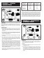
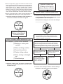
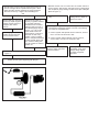
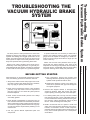
The three phases of tests presented here have been
designed to discover the presence of both vacuum and
hydraulic fluid leakage and sluggish performance of the
brakes. The entire system from the vacuum service to the
wheel cylinder or caliper can be easily checked in a relatively short period of time by performing these tests.
When working on or around brake systems and components, the following precautions should be observed:
1. Always block vehicle wheels. Stop engine when working under a vehicle. Keep hands away from chambers;
they may apply as system pressure drops.
2. Never connect or disconnect a hose or line containing
pressure; it may whip. Never remove a component or
pipe plug unless you are certain all system pressure
has been depleted.
3. Never exceed recommended pressure and always
wear safety glasses.
4. Never attempt to disassemble a component until you
have read and understand recommended procedures.
Some components contain powerful springs and injury
can result if not properly disassembled. Use only proper tools and observe all precautions pertaining to use
of these tools.
5. Use only genuine Bendix replacement parts and
components.
A. Only components, devices and mounting and
attaching hardware specifically designed to use in
hydraulic brake systems should be used.
B. Replacement hardware, tubing, hose, fittings, etc.
should be of equivalent size, type and strength as
the original equipment.
6. Devices with stripped threads or damaged parts
should be replaced. Other than drums and rotors,
repairs requiring machining should not be attempted.
7. For cleaning brake parts, use only new DOT 4 brake
fluid, isopropyl alcohol or clear methylated spirits. Do
not use mineral base cleaning solvents such as gasoline, kerosene, carbon tetrachloride, acetone or paint
thinner - these will damage the rubber parts.
8. Bendix recommends that for optimum results and
safety, worn units should be replaced by new units. If,
however, it is decided to service a used component,
particular attention should be paid to the following, but
in any case of doubt replace the unit or seek professional advice.
DATE:
BEFORE GETTING STARTED
TRUCK
Please note that the tests presented here are performed with the vehicle stationary. They must not be
interpreted as overruling the importance and necessity of
functional dynamic controllability tests and other testing
required in assuring vehicle safety and performance.
MECHANIC:
While in many cases a problem can be found and corrected early in the testing procedure, it is generally recommended that all three phases of testing be completed
to assure that the entire system is in good working order.
To perform these tests it is necessary to obtain both a
vacuum and hydraulic pressure gauge. The hydraulic
gauge should be capable of readings up to 2000 P.S.I.
while the vacuum gauge should have a range up to 30
inches of mercury.
Troubleshooting The
Vacuum Hydraulic Brake System
TROUBLESHOOTING THE
VACUUM HYDRAULIC BRAKE
SYSTEM
PHASE I – VISUAL
INSPECTION
Brake Fluid
Type
Boiling Point
Dry
Boiling Point
Wet
DOT #3
401°F
284°F
DOT #4
446°F
311°F
DOT #5
(silicone)
500°F
500°F
With the master cylinder cover off, have an assistant slowly make
a full brake application while observing the fluid in the reservoir.
CAUTION. Wear eye protection and do not allow fluid to contact
vehicle's painted finish. A small spurt or geyser at the beginning of
the brake application followed by continued fluid turbulence indicates internal master cylinder leakage. Repair or replace. If the
fluid remains calm after initial spurt, continue to Phase II Testing.
GENERAL
PHASE II – HYDRAULIC
SYSTEM TESTS
Phase I visual inspection procedures should reveal the most common problems found in a hydraulic brake system. The inspection
steps are presented in the order in which they are most easily
performed.
INSPECTION
1. Look for signs of fluid leakage at connection points as well as
around wheel cylinder calipers, the master cylinder and
hydrovac. Inspect disc brakes caliper piston boots for tears or
deterioration.
2. Inspect the master cylinder pedal and linkage for binding, bending or damage. Lubricate rotating and sliding components with
a rubber compatible lubricant.
3. Inspect the foundation brakes for proper adjustment and adjust
if necessary.
4. Start engine and have assistant make several brake applications while visually inspecting all hydraulic and vacuum lines,
hoses, and clamps for kinking, chafing, damage, corrosion and
signs of collapsing or "ballooning".
5. Remove the master cylinder reservoir cover and check the fluid
level. Refill as necessary. While the cover is off, look for discoloration, cloudiness, and "gumming" of the fluid. Also look for
corrosion on any part in contact with the fluid. If any of these
conditions are found, the system should be drained, bled,
flushed and refilled with the proper type of brake fluid for the
application. DO NOT MIX HYDRAULIC FLUID AND BRAKE
FLUID. "GUMMING" OF FLUID AND DAMAGE TO COMPONENT SEALS WILL RESULT.
Federal Motor Vehicle Safety Standard #116 divides brake
fluids into three categories with the primary difference being the
fluid boiling points.
GENERAL
1. With the engine off and brakes not applied, install a 0-2000 p.s.i.
hydraulic gauge at the wheel cylinder or caliper and bleed air
from the gauge and its connecting line.
NOTES:
A. The gauge can usually be installed by removing the wheel
cylinder bleed screw.
B. When the vehicle is equipped with a dual or "split" brake system, a gauge must be installed in each side of the system,
i.e.; one gauge in a front axle brake and one gauge in a rear
axle brake. Alternatively, the tests can be performed twice,
once for the front axle brakes and again for the rear axle
brakes.
2. With the engine idling, apply and release the brakes several
times. Note that the pressure is registered on the gauge with the
brakes applied and that each time the brakes are released the
gauge returns to 0 p.s.i. NOTE: In systems where a residual
check valve is used the pressure will not return to 0 p.s.i.
Between 3 and 50 p.s.i. pressure will remain when the brakes
are released. RESIDUAL CHECK VALVES MUST NOT BE
USED TO HOLD PRESSURE ON A DISC BRAKE CALIPER.
3. With the engine idling make a rapid, full brake application and
hold it applied while observing one of four gauge reactions.
A. Pressure instantly rises to between 1000 and 2000 p.s.i.
and remains constant while brakes are applied.
Hydraulic System Okay
Problem is most likely in
Vacuum System or Booster
Perform Phase III Vacuum System Tests
C. Pressure rises slowly but remains constant while brakes
are held applied. Final pressure reading may be very low
or may be between 1000 and 2000 p.s.i.
Record pressure reading here if it is less than 1000 p.s.i.
______________________.
Hydraulic System Okay
Problem is most likely in
Foundation Brakes
Check Foundation Brakes Mechanical Parts
For Example: (1) Drum or rotor condition
(2) Backing or anchor plate
condition
While applying and releasing brakes, inspect hydraulic
lines and hoses for kinks, bends, "ballooning" and
restrictions that may not have been found in Phase I
inspections. Replace as necessary.
Release brake application, then remove atmospheric air
hose from vacuum booster control valve. (NOTE: This is
the hose running between the booster and its externally
mounted filter generally found in the cab.) Make a full and
rapid brake application and again observe gauge at wheel.
(3) Shoe and lining condition
(4) Correct lining friction
(5) Caliper sliding surfaces
(6) Worn, missing or damaged
part
(7) Wheel bearings
Hydraulic pressure rises
instantly to between 1000
and 2000 p.s.i.
Hydraulic pressure rises
slowly to same pressure
recorded above.
Repair or replace atmospheric air filter and/or
connecting hose fittings.
Return to beginning of
Step 3 and retest.
Perform Phase III Vacuum
System Tests
B. Pressure instantly rises and remains constant while
brakes are held applied but pressure does not reach a
minimum 1000 p.s.i.
D. Pressure rises instantly to between 1000 and 2000 p.s.i.
but begins to drop while brakes are held applied.
Turn off engine. Make 10-15 full brake applications to get rid
of all vacuum. Make and hold a full brake application and
observe gauge at wheel. Pressure valve is not important.
Watch for a pressure drop.
Pressure rises instantly
and remains constant while
brakes are held applied.
Pressure rises instantly but
begins to fall while brakes
are held applied.
Hydraulic system okay.
Vacuum leakage most likely
causing the pressure drop.
Vacuum system probably
not causing pressure drop.
Hydraulic leakage most
likely causing pressure
drop.
There are two possible gauge results; proceed to the correct heading and continue testing.
A. Vacuum gauge reading is 16 inches of mercury or higher.
Vacuum reaching booster is okay.
Shut off engine and note any change in vacuum gauge. The
following are maximum acceptable leakage limits:
1. Vacuum system with separate vacuum reservoir; a drop
of no more than 2" HG in 60 seconds.
Perform Phase III Vacuum
System Checks.
Perform Steps 1, 4, 5 of
Phase I Visual Inspection
again. Return to beginning
of Step 3 and retest.
2. Vacuum system without separate vacuum reservoir; a
drop of no more than 2" HG in 15 seconds.
Leakage is okay. Proceed to
Step 3 and continue testing.
PHASE III – VACUUM
SYSTEM TESTS
Leakage NOT okay. To
pinpoint leakage source,
reinstall gauge at positions
indicated in Figure 3 and
retest at each position.
Begin at position #3 to test
hose between check valve
and vacuum source. Repair
or replace components
ahead of gauge when
unacceptable leakage is
noted. Continue testing
until leakage checks okay
at position #1.
Leakage is okay. Proceed to
Step 3 and continue testing.
B. Vacuum gauge reading is less than 16 inches of mercury.
Insufficient vacuum is reaching the booster.
GENERAL
1. Remove vacuum line from booster control valve section and
install a vacuum gauge with a range of 0-30 inches of mercury
in the end of the line. (Refer to Figure 3 Gauge Position #1.)
2. Start engine and allow to idle for several minutes to allow vacuum gauge reading to stabilize, then read gauge. Vacuum should
be a minimum of 16 inches of mercury. Record gauge reading
here _________________" HG for use later.
Shut off engine. Connect vacuum gauge at the source of
vacuum on engine which is position #2 in Figure 3. Start
engine and idle. Vacuum registered on gauge should be
16 inches of mercury or higher. Record reading here:
_____________________" HG.
3. Reinstall vacuum hose at control valve of booster and tee in
vacuum gauge. Start engine and build vacuum. Read gauge
and compare to gauge reading recorded in first part of Step #2.
(Refer to Figure 4.)
Reading is same, booster
okay.
Vacuum less than 16 inches
of mercury. Repair engine or
replace vacuum pump if so
equipped, then retest
vacuum.
Remove gauge from
position #2 and reconnect
hose to vacuum source.
Vacuum is 16 inches of
mercury or greater. Problem
is most likely restricted
lines/devices or excessive
leakage. Refer to Figure 3
and reinstall gauge at positions 3, 4, 5, 6 & 1 in that
order. Retest vacuum at
each position. If vacuum is
less than 16" HG at any
position, repair or replace
hose or component between
current and last gauge position. Continue testing until
16" HG or better is noted at
position #1.
Reconnect vacuum gauge at position #1 as illustrated in
Figure 3.
Retest vacuum system beginning with Step #1.
Reading is lower. Booster is
leaking vacuum. Repair or
replace and retest.
With engine idling make 10 rapid brake applications and
note the time required for vacuum to recover. The following
are maximum acceptable limits.
A. Vacuum system with separate vacuum reservoir; vacuum
rise to 16" HG in 30 seconds or less.
B. Vacuum system without separate vacuum reservoir;
vacuum rise to 16" HG in 15 seconds or less.
Recovery time is acceptable.
Remove gauge and return
vehicle to service.
Recovery time not
acceptable. Check hose,
clamps, fittings. Repair
or replace if required
and retest.
NOW – The most complete stock of original equipment replacement parts for all
medium truck and school bus hydraulic brake systems.
SEE YOUR BENDIX PARTS OUTLET FOR:
POWER BRAKE
DISC BRAKE
DRUM BRAKE
• Hydrovacs
• Calipers and Repair Kits
• Vacuum Pumps
• Hardware Kits
• Wheel Cylinders and
Repair Kits
• Hydromax
• Rotors
• Air-paks
• Disc Pads
• Master Cylinders and
Repair Kits
• Pistons
• Detail Parts
• Anchor Supports
• Brake Lining
• Power Brake Repair Kits
Also
• Brake Hose & Tubing
• Fittings
• Brake Fluid
• Vacuum Hose
THE AIR AND HYDRAULIC BRAKE EXPERTS
BW1399 © 2003 Bendix Commercial Vehicle Systems LLC
All rights reserved.
2/2003 Printed in U.S.A.