1
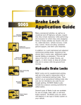
Brake Lock
Application
Guide
Many commercial vehicles, as well as
recreational and off-highway vehicles,
require that they remain stationary while
performing the functions for which they
were designed. Some of these vehicles
are found in the utility, cable television,
vehicle recovery, multi-stop, transit,
refuse recycling, sanitation, ground
support, lawn care, and recreational
industries.
In addition to a well maintained and
adjusted mechanical parking brake,
experience has shown that in many
uses, additional supplemental holding is
necessary. This can be done in the form
of wheel chocks, outriggers, or other
means to keep all wheels that are in
contact with the ground from moving.
Hydraulic Brake Locks
MICO Locks are for supplemental
parking and are to be used in
conjunction with a vehicle's mechanical
parking brake. They perform as an
operational holding brake only and are
not intended to be used for prolonged
parking. All MICO Brake Locks include
low pressure warning switch(s) for
added safety.
Several types of Brake Locks are
available for use in single, dual, split, or
anti-lock brake systems. The Brake
Lock you select will depend on the type
of brake system on your vehicle.
MICO, Inc.
Form No. 80-950-152
Revised 2012-12-14
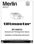
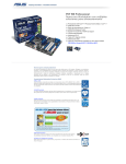
Brake Lock Product Line
691 Brake Lock System
(Patent Number 5,505,528)
User Interface
Control Module
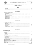
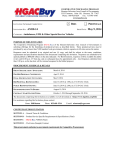
MICO 691 Brake Lock Systems lock hydraulic pressure in the service brakes
to supplement the vehicle's original equipment parking brake and provide
extra holding in heavy-duty and high frequency applications. These systems
also function as an interlock to apply pressure to the service brakes when
other vehicle mounted equipment is being used.
The 691 System consists of a small electrohydraulic pump, remote mounted
actuator (single and/or dual), electronic control module, and a small dash
mounted user interface. The operator simply activates a switch and the 691
System automatically applies, monitors, and maintains brake-locking pressure.
A 691 Brake Lock will significantly enhance vehicle holding capability while
not interfering with normal service brake function.
All MICO Brake Lock Systems are for vehicles using Brake Fluid braking
systems.
MODELS:
02-691-101
Single Brake Lock System
(for vehicles over 19,000 GVW)
02-691-109
Power Unit
Single Brake Lock System
(for vehicles under 19,000 GVW)
02-691-201
Dual Brake Lock System
(for vehicles over 19,000 GVW)
02-691-209
Dual Brake Lock System
(for vehicles under 19,000 GVW)
02-691-303
3-Channel Anti-Lock Brake Lock System
(for vehicles over 19,000 GVW)
Single Actuator
02-691-305
3-Channel Anti-Lock Brake Lock System
(for vehicles under 19,000 GVW)
02-691-403
4-Channel Anti-Lock Brake Lock System
(for vehicles over 19,000 GVWoptional on others.)
NOTE: 691 Power Unit uses silicone fluid.
See page 14 for 691 Models and Sub-Components.
Dual Actuator
Wire Harness
2
MICO, Inc.
Form No. 80-950-152
Revised 2012-12-14
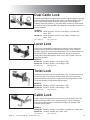
Dual Cable Lock
Dualocks are designed to supplement a vehicle's original equipment parking
brake by utilizing the hydraulic service brakes of a vehicle equipped with a
dual or split braking system. Dualocks can provide 4-wheel lockup for
hydraulic dual brake systems or rear wheel ABS, as well as 2-wheel lockup
for hydraulic 3 and 4 channel ABS. Each Dualock includes two low pressure
warning switches.
MODELS:
02-640-169 Cable operated - 3/16 & 1/4 inch fittings - includes 10 ft.
cable - (BF)
02-640-202 Cable operated - 3/16 & 1/4 inch fittings - includes 10 ft.
cable - (HO)
(BF) = Brake Fluid
(HO) = Hydraulic Oil
Lever Lock
Lever Locks are designed to supplement a vehicle's original equipment
parking brake by utilizing the hydraulic service brakes. Lever Locks are
manually operated one-way check valves which lock fluid under pressure in
the selected brakes. Hand operation leaves the operator’s feet free for
clutch and throttle pedal operation. Each Lever Lock includes a low pressure warning switch.
MODELS:
02-640-125 Includes - 3/16 & 1/4 inch fittings - (BF)
02-640-126 Includes - 3/16 & 1/4 inch fittings - (HO)
(BF) = Brake Fluid
(HO) = Hydraulic Oil
Twist Lock
Twist Locks are functionally the same as lever locks. The differences being
a Twist Lock has a rotary action handle and the push rod is sealed and
lubricated with silicone grease for tough environmental applications. Each
Twist Lock includes a low pressure warning switch.
MODELS:
03-640-075 Includes - 3/16 & 1/4 inch fittings - (BF)
03-640-076 Includes - 3/16 & 1/4 inch fittings - (HO)
(BF) = Brake Fluid
(HO) = Hydraulic Oil
Cable Lock
Cable Locks are functionally the same as lever locks and twist locks. The
difference being a Cable Lock is cable operated for remote mountings
when space under the dash is limited. Each Cable Lock includes a low
pressure warning switch.
MODELS:
02-640-023 Includes - 3/16 & 1/4 inch fittings - includes 10 ft. cable - (BF)
02-640-122 Includes - includes 10 ft. cable - (HO)
(BF) = Brake Fluid
MICO, Inc.
Form No. 80-950-152
Revised 2012-12-14
(HO) = Hydraulic Oil
3
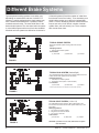
Different Brake Systems
Typical hydraulic braking systems in use today vary
depending on manufacturer and size of vehicle. For
instance, a vehicle equipped with a single system may
have a firewall mounted booster or possibly a frame
mounted remote booster. The same holds true for the
dual and split systems. The rear wheel anti-lock system
is a dual brake system with an anti-lock valve installed.
All-wheel anti-lock systems are defined as 3-channel or
4-channel systems (Check the number of outlet lines
from the anti-lock control valve). To be absolutely sure
which braking system your vehicle is equipped with,
check it. Look for identifying features such as dual flex
lines at rear axle or front wheels, number of master
cylinder lines, anti-lock valve(s), etc. Then, compare
with circuits shown here.
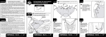
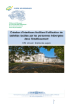
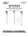
TYPICAL SINGLE SYSTEM
One single hydraulic system serving both front and rear
brakes.
Identifying Feature:
1. One line from master cylinder.
Lock Position:
(1) Front axle
(2) Rear axle
(3) 4-wheel
FIGURE 1
TYPICAL DUAL SYSTEM (Vertical Split)
Two independent braking systems. One system leads to the front
brakes and the other system to the rear brakes.
Identifying Features:
1. Two lines from master cylinder.
2. Combination valve (used on some models).
Lock Position:
(3) 4-wheel
(1) Front axle
(2) Rear axle*
* Some imported vehicles use two separate air boosted master cylinders.
FIGURE 2
TYPICAL SPLIT SYSTEM (1 1/2 x 1/2)
Two independent braking systems. One system leads to the
front and the rear brakes and the other system leads only to the
rear brakes.
Identifying Features:
1. Two lines from master cylinder.
2. Single hose to each front wheel.
3. Two hoses to rear axle.
Lock Position:
(1) Front axle
(2) Rear axle
(3) 4-wheel
FIGURE 3
4
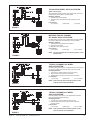
CAUTION: If position 2 or 3 is used, both halves of system
must be locked.
MICO, Inc.
Form No. 80-950-152
Revised 2012-12-14
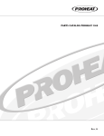
TYPICAL REAR WHEEL ANTI-LOCK SYSTEM
(Dual Vertical Split)
Two independent braking systems. One system leads to the front
brakes and the other system to the rear brakes.
Identifying Features:
1. Two lines from master cylinder.
2. Anti-lock control valve between master cylinder and rear
wheels.
Lock Position:
(1) Front axle
(2) Rear axle
(3) 4-wheel
FIGURE 4
IMPORTED TRUCK 3-CHANNEL
ALL-WHEEL ANTI-LOCK SYSTEM
Provides braking control by way of independent anti-lock channels
for each rear wheel and a third channel for the front wheels.
Identifying Features:
1. Three separate air/hydraulic brake boosters.
2. One line to front brakes.
3. Separate lines to each rear wheel.
Lock Position:
(1) Front axle
(2) Rear axle
(1 & 2) 4-wheel
NOTE: The anti-lock functions on air booster system, not the
hydraulic side.
FIGURE 5
TYPICAL 3-CHANNEL ALL-WHEEL
ANTI-LOCK SYSTEM
Provides braking control by way of independent anti-lock channels
for each front wheel and a third channel for both rear wheels.
Identifying Features:
1. Two lines from master cylinder to anti-lock valve(s).
2. One line from anti-lock valve to rear brakes.
3. Separate lines from anti-lock valve to each front wheel.
Lock Position:
(1) Front axle
(2) Rear axle
(1 & 2) 4-wheel
NOTE: Some 3-channel anti-lock brake systems use two
separate anti-lock valve assemblies.
FIGURE 6
TYPICAL 4-CHANNEL ALL-WHEEL
ANTI-LOCK SYSTEM
Provides braking control by way of an independent channel for
each front wheel and each rear wheel.
Identifying Features:
1. Two lines from master cylinder to anti-lock valve.
2. Separate lines from anti-lock valve to each of the front
and rear wheels.
Lock Position:
(1) Front axle
(2) Rear axle
(1 & 2) 4-wheel
NOTE: Some 4-channel anti-lock brake systems use two
separate anti-lock valve assemblies.
FIGURE 7
MICO, Inc.
Form No. 80-950-152
Revised 2012-12-14
5
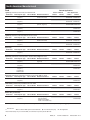
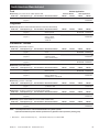
North American Manufactured
Chevrolet - GMC
Vehicle Application
Light Duty (C/K10, C/K1500)
Aerial Lift Bucket
Model Year
Brake System Type
1967-1987
Dual
(Figure 2)
F-disc/R-drum
1988-1994
Rear ABS
(Figure 4)
1995-2009
2010-2013
Other Applications
4 Wheel
2 Wheel
4 Wheel
2 Wheel
02-691-209
02-691-109
02-691-209
02-640-169
02-691-109
02-640-125
F-disc/R-drum
02-691-209
02-691-109
02-691-209
02-640-169
02-691-109
02-640-125
3-channel ABS
(Figure 6)
F-disc/R-drum
02-691-305
02-691-109* 02-691-305
02-691-109*
02-640-125*
4-channel ABS
(Figure 7)
F-disc/R-drum
02-691-403
02-691-209
02-691-209
02-640-169
Light Duty (C/K20-30, C/K2500-4500)
Model Year
Brake System Type
Service Brakes Miscellaneous Notes
Early models had 4
wheel drum brakes.
Service Brakes Miscellaneous Notes
1967-1987
Dual
(Figure 2)
F-disc/R-drum
1988-1994
Rear ABS
(Figure 4)
1995-2013
3-channel ABS
(Figure 6)
Early models had 4
wheel drum brakes.
Aerial Lift Bucket
4 Wheel
2 Wheel
02-691-403
Other Applications
4 Wheel
2 Wheel
02-691-209
02-691-109
02-691-209
02-640-169
02-691-109
02-640-125
F-disc/R-drum
02-691-209
02-691-109
02-691-209
02-640-169
02-691-109
02-640-125
F-disc/R-drum
02-691-305
02-691-109* 02-691-305
02-691-109*
02-640-125*
3500HD (All models have Hydraulic Boost Master Cylinders)
Model Year
Brake System Type
Service Brakes Miscellaneous Notes
1990-1992
Dual
(Figure 2)
4 wheel disc
1993-1994
Rear ABS
(Figure 4)
4 wheel disc
1995-2002
3-channel ABS
(Figure 6)
4 wheel disc
4 Wheel
2 Wheel
4 Wheel
2 Wheel
Load sensing valve at
rear axle.
02-691-209
02-691-109
02-691-209
02-640-169
02-691-109
02-640-125
Load sensing valve at
rear axle.
02-691-209
02-691-109
02-691-209
02-640-169
02-691-109
02-640-125
02-691-305
02-691-109* 02-691-305
02-691-109*
02-640-125*
Medium Duty (C50-C65, Kodiak & TopKick, C4500-C7500 Conventional Cab, T5500-T7500 Tilt Cab - Also Isuzu H-Series Conventional Cab)
Model Year
Brake System Type
Service Brakes Miscellaneous Notes
4 Wheel
2 Wheel
4 Wheel
2 Wheel
1970-mid 1980s
Single
(Figure 1)
Drum
Vacuum/Hydraulic
Boost
02-691-101
02-691-101
02-691-101
02-640-023
02-691-101
02-640-023
1970-mid 1980s
Dual
(Figure 2)
Drum
Vacuum/Hydraulic
Boost
02-691-201
02-691-101
02-691-201
02-640-169
02-691-101
02-640-023
1970-mid 1980s
1 1/2 x 1/2 split
(Figure 3)
Drum
A dual brake lock is
required for either
rear or 4 wheel lockup.
02-691-201
02-691-201
02-691-201
02-691-201
02-640-023u
mid ‘80s-1996
Dual
(Figure 2)
4 wheel disc
Hydraulic Boosted
Master Cylinder.
02-691-201
02-691-101
02-691-201
02-640-169
02-691-101
02-640-023
1997-2009
4-channel ABS
(Figure 7)
4 wheel disc
4-channel ABS standard. 02-691-403
Option to delete available
prior to 1 Mar 99. :
02-691-209
02-691-403
02-691-209
02-640-169
: With 4-channel ABS deleted, brake system type is Dual (Figure 2)
NOTE: Vacuum/Hydraulic Boost = Vacuum assisted booster for hydraulic cylinder
Hydraulic Boost Master Cylinder = Master cylinder driven by hydraulic booster powered by steering pump
Best Choice
6
u Front wheel lockup only
*Rear wheel lockup only on 3-channel ABS
MICO, Inc.
Form No. 80-950-152
Revised 2012-12-14
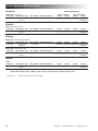
North American Manufactured
Dodge - Ram
Vehicle Application
Light Duty (D100, Ram 1500)
Aerial Lift Bucket
Model Year
Brake System Type
mid 70’s-1988
Dual
(Figure 2)
1989-1993
Other Applications
4 Wheel
2 Wheel
4 Wheel
2 Wheel
F-disc/R-drum
02-691-209
02-691-109
02-691-209
02-640-169
02-691-109
02-640-125
Rear ABS
(Figure 4)
F-disc/R-drum
Anti-lock valve location at 02-691-209
rear axle makes it difficult
to install lock downstream
from anti-lock valve. Single
locks should go on front axle.
02-691-109
02-691-209
02-640-169
02-691-109
02-640-125
1994-1998
Rear ABS
(Figure 4)
F-disc/R-drum
3-channel ABS optional.
(Figure 6)
1999-2006
3-channel ABS
(Figure 6)
F-disc/R-drum
in 2001-2005
model year
4 wheel disc
all models
2006-2011
model year
4-channel ABS
(Figure 7)
4 wheel disc
`
2007-2013
Service Brakes Miscellaneous Notes
02-691-209s 02-691-109* 02-691-209s 02-691-109*
02-640-125*
Rear ABS (Figure 4)
02-691-305
standard on ST, STL;
3-channel ABS (Figure 6)
standard on STX, Laramie,
optional on others.
02-691-109* 02-691-305
02-691-109*
02-640-125*
MY 2007-2008 ST,
STL had Rear ABS
(Figure 4) standard,
4-channel ABS
optional (Figure 7)
02-691-209
02-691-209
02-640-169
Light Duty (D250-D350, Ram 2500-3500)
Model Year
Brake System Type
Service Brakes Miscellaneous Notes
02-691-403
02-691-403
4 Wheel
2 Wheel
4 Wheel
2 Wheel
mid 70’s-1988
Dual
(Figure 2)
F-disc/R-drum
02-691-209
02-691-109
02-691-209
02-640-169
02-691-109
02-640-125
1989-1993
Rear ABS
(Figure 4)
F-disc/R-drum
Anti-lock valve location at 02-691-209
rear axle makes it difficult
to install lock downstream
from anti-lock valve. Single
locks should go on front axle.
02-691-109
02-691-209
02-640-169
02-691-109
02-640-125
1994-1998
Rear ABS
(Figure 4)
F-disc/R-drum
3-channel ABS optional.
(Figure 6)
1999-2012
3-channel ABS
(Figure 6)
F-disc/R-drum
4 wheel disc
in 2001-2005
model year
4 wheel disc
all models
2006-2012
model year
02-691-305
02-691-109* 02-691-305
02-691-109*
02-640-125*
2013
4-channel ABS
(Figure 7)
4 wheel disc
02-691-403
02-691-209
02-691-403
02-691-209
02-640-169
4 Wheel
2 Wheel
4 Wheel
2 Wheel
Medium Duty (Ram 4500-5500)
Model Year
Brake System Type
Service Brakes Miscellaneous Notes
02-691-209s 02-691-109* 02-691-209s 02-691-109*
02-640-125*
2008-2012
3-channel ABS
(Figure 6)
4 wheel disc
02-691-305
02-691-109* 02-691-305
02-691-109*
02-640-125*
2013
4-channel ABS
(Figure 7)
4 wheel disc
02-691-403
02-691-209
02-691-209
02-640-169
02-691-403
NOTE: Vacuum/Hydraulic Boost = Vacuum assisted booster for hydraulic cylinder
Hydraulic Boost Master Cylinder = Master cylinder driven by hydraulic booster powered by steering pump
Best Choice
MICO, Inc.
s On 3-channel ABS Systems use 02-691-305
Form No. 80-950-152
Revised 2012-12-14
*Rear wheel lockup only on 3-channel ABS
7
North American Manufactured
Ford
Vehicle Application
Light Duty (E150-E250, F150-F250) below 8600 lb GVW
Aerial Lift Bucket
Service Brakes Miscellaneous Notes
Other Applications
Model Year
Brake System Type
1967-1986
Dual
(Figure 2)
F-disc/R-drum
1987-1996
Rear ABS
(Figure 4)
F-disc/R-drum
1997-2003
Rear ABS
(Figure 4)
F-disc/R-drum
2004-2009
3-channel ABS
(Figure 6)
4 wheel disc
02-691-305
02-691-109* 02-691-305
02-691-109*
02-640-125*
2010-2013
4-channel ABS
(Figure 7)
4 wheel disc
02-691-403
02-691-209
02-691-109
02-640-169
Early models had 4
wheel drum brakes.
3-channel ABS
optional. (Figure 6)
4 Wheel
2 Wheel
4 Wheel
2 Wheel
02-691-209
02-691-109
02-691-209
02-640-169
02-691-109
02-640-125
02-691-209
02-691-109
02-691-209
02-640-169
02-691-109
02-640-125
02-691-209s 02-691-109* 02-691-209s 02-691-109*
02-640-169s 02-640-125*
02-691-403
Light Duty (E250-E35, F250-F350) 8600 lb and above GVW
Model Year
Brake System Type
Service Brakes Miscellaneous Notes
1967-1986
Dual
(Figure 2)
F-disc/R-drum
1987-1998
Rear ABS
(Figure 4)
F-disc/R-drum
Super Duty
Model Year
1988-1998
Brake System Type
Dual
(Figure 2)
Early models had 4
wheel drum brakes.
4 Wheel
2 Wheel
4 Wheel
2 Wheel
02-691-209
02-691-109
02-691-209
02-640-169
02-691-109
02-640-125
02-691-209
02-691-109
02-691-209
02-640-169
02-691-109
02-640-125
Service Brakes Miscellaneous Notes
4 wheel disc
4 Wheel
2 Wheel
4 Wheel
2 Wheel
02-691-209
02-691-109
02-691-209
02-640-169
02-691-109
02-640-125
4 Wheel
2 Wheel
4 Wheel
2 Wheel
Super Duty (E250-E350, F250-F350) Below 10,000 lb GVW, single rear wheel
Model Year
Brake System Type
Service Brakes Miscellaneous Notes
3-channel ABS optional.
(Figure 6)
02-691-209s 02-691-109* 02-691-209s 02-691-109*
02-640-169s 02-640-125*
1999-2000
Rear ABS
(Figure 4)
4 wheel disc
2001-2010
3-channel ABS
(Figure 6)
4 wheel disc
02-691-305
02-691-109* 02-691-305
02-691-109*
02-640-125*
2011-2013
4-channel ABS
(Figure 7)
on single rear
wheel models
4 wheel disc
02-691-403
02-691-209
02-691-403
02-691-209
02-640-169
2 Wheel
4 Wheel
Super Duty (E350-E450, F350-F550) 10,000 lb and over GVW, dual rear wheel
Model Year
Brake System Type
Service Brakes Miscellaneous Notes
1999-2013
3-channel ABS
(Figure 6)
4 wheel disc
4 Wheel
02-691-305
02-691-109* 02-691-305
2 Wheel
02-691-109*
02-640-125*
Medium Duty (F650-F750), 23,000 lb and over GVW
Model Year
Brake System Type
2001-2013
4-channel ABS
(Figure 7)
Medium Duty (F500-F800)
Model Year
Brake System Type
1984-1999
Dual
(Figure 2)
Service Brakes Miscellaneous Notes
4 wheel disc
4 Wheel
2 Wheel
4 Wheel
2 Wheel
02-691-403
02-691-209
02-691-403
02-691-209
02-640-169
4 Wheel
2 Wheel
4 Wheel
2 Wheel
Service Brakes Miscellaneous Notes
Drum or Disc/drum
OEM spring-apply
rear park brakes
standard. Use MICO
Locks on front bakes only.
NA
02-691-101u
NA
02-691-101u
02-640-023u
NOTE: Hydraulic Boost Master Cylinder = Master cylinder driven by hydraulic booster powered by steering pump
Best Choice
s On 3-channel ABS systems use 02-691-305
u Front wheel lockup only
NA Not Applicable
* Rear wheel lockup only on 3-channel ABS, for front wheel only lockup use 02-691-223.
8
MICO, Inc.
Form No. 80-950-152
Revised 2012-12-14
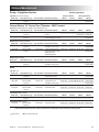
North American Manufactured
Ford
Vehicle Application
Medium Duty (LCF) Cab Forward 16,000-19,500 lb GVW
Model Year
Brake System Type
2005-2010
3-channel ABS
(Figure 4)
Aerial Lift Bucket
Service Brakes Miscellaneous Notes
4 wheel disc
4 Wheel
02-691-305
2 Wheel
Other Applications
4 Wheel
02-691-109* 02-691-305
2 Wheel
02-691-109*
02-640-023*
Freightliner
Medium Duty (Business Class F50-F80, Business Class M2, MT35-MT55)
Model Year
Brake System Type
4 Wheel
2 Wheel
4 Wheel
2 Wheel
1991-1996
Dual
(Figure 2)
Service Brakes Miscellaneous Notes
4 wheel disc
Hydraulic Boost
Master Cylinder.
02-691-201
02-691-101
02-691-201
02-640-169
02-691-101
02-640-023
1997-2013
4-channel ABS
(Figure 7)
4 wheel disc
4-channel ABS standard.
Option to delete
available prior to
3/1/99. :
02-691-403
02-691-209
02-691-403
02-691-209
02-640-169
International - Navistar
Medium Duty (S1600-S1800 "Loadstar")
Model Year
Brake System Type
4 Wheel
2 Wheel
4 Wheel
2 Wheel
1970-1987
Single
(Figure 1)
Drum
Vacuum/Hydraulic.
Boost
02-691-101
02-691-101
02-691-101
02-640-023
02-691-101
02-640-023
1970-1987
1 1/2 x 1/2 split
(Figure 3)
Drum
A dual brake lock is
required for either
rear or 4 wheel lockup.
02-691-201
02-691-201
02-691-201
02-691-201
02-640-023u
1970-1987
Dual
(Figure 2)
Drum
Hydrovac(s)
02-691-201
02-691-101
02-691-201
02-640-169
02-691-101
02-640-023
Medium Duty (Series 4600-4900’s)
Model Year
Brake System Type
Service Brakes Miscellaneous Notes
4 Wheel
2 Wheel
4 Wheel
2 Wheel
1988-1998
Dual
(Figure 2)
4 wheel disc
Hydraulic Boosted
Master Cylinder.
02-691-201
02-691-101
02-691-201
02-640-169
02-691-101
02-640-023
1999-2001
4-channel ABS
(Figure 7)
4 wheel disc
4 channel ABS standard. 02-691-403
Option to delete was
available prior to 1 Mar 99. :
02-691-209
02-691-403
02-691-209
02-640-169
Medium Duty ("Durastar" 4100-4300)
Model Year
Brake System Type
2002-2013
4-channel ABS
(Figure 7)
Service Brakes Miscellaneous Notes
Service Brakes Miscellaneous Notes
4 wheel disc
2009 and newer models
use Merritor HPB
Medium Duty ("TerraStar" Conventional cab 16,000-19,500 lb GVW)
Model Year
Brake System Type
Service Brakes Miscellaneous Notes
2011-2013
3-channel ABS
(Figure 6)
4 wheel disc
4 Wheel
2 Wheel
4 Wheel
2 Wheel
02-691-403
02-691-209
02-691-403
02-691-209
02-640-169
2 Wheel
4 Wheel
4 Wheel
02-691-305
02-691-109* 02-691-305
2 Wheel
02-691-109*
02-640-125*
Medium Duty (Citystar CF500-CF600 Cab Forward 16,000-19,500 lb GVW)
Model Year
Brake System Type
2005-2010
3-channel ABS
(Figure 6)
Service Brakes Miscellaneous Notes
4 wheel disc
4 Wheel
02-691-305
2 Wheel
4 Wheel
02-691-109* 02-691-305
2 Wheel
02-691-109*
02-640-023*
: With 4-channel ABS deleted, brake system type is Dual (Figure 2)
NOTE: Vacuum/Hydraulic Boost = Vacuum assisted booster for hydraulic cylinder
Hydraulic Boost Master Cylinder = Master cylinder driven by hydraulic booster powered by steering pump
Best Choice
MICO, Inc.
u Front wheel lockup only
Form No. 80-950-152
* Rear wheel lockup only on 3-channel ABS
Revised 2012-12-14
9
North American Manufactured
Kenworth
Vehicle Application
Medium Duty (T170-T-370)
Model Year
Brake System Type
2001-2013
4-channel ABS
(Figure 7)
Aerial Lift Bucket
Service Brakes Miscellaneous Notes
4 wheel disc
Other Applications
4 Wheel
2 Wheel
4 Wheel
2 Wheel
02-691-403
02-691-209
02-691-403
02-691-209
02-640-169
Peterbilt
Medium Duty (Model 325-337)
Model Year
Brake System Type
2001-2013
4-channel ABS
(Figure 7)
Service Brakes Miscellaneous Notes
4 wheel disc
4 Wheel
2 Wheel
4 Wheel
2 Wheel
02-691-403
02-691-209
02-691-403
02-691-209
02-640-169
2 Wheel
4 Wheel
Sterling
Medium Duty ("Bullet" CONV45-CONV55)
Model Year
Brake System Type
2008-2009
3-channel ABS
(Figure 6)
Service Brakes Miscellaneous Notes
4 wheel disc
4 Wheel
02-691-305
02-691-109* 02-691-305
2 Wheel
02-691-109*
02-640-125*
Medium Duty ("Actera" 5500-7500)
Model Year
Brake System Type
2001-2009
4-channel ABS
(Figure 7)
Service Brakes Miscellaneous Notes
4 wheel disc
4 Wheel
2 Wheel
4 Wheel
2 Wheel
02-691-403
02-691-209
02-691-403
02-691-209
02-640-169
4 Wheel
2 Wheel
4 Wheel
2 Wheel
02-691-403
02-691-209
02-691-403
02-691-209
02-640-169
Toyota
Tundra
Model Year
Brake System Type
2008-2013
4-channel ABS
(Figure 7)
Service Brakes Miscellaneous Notes
4 wheel disc
NOTE: Vacuum/Hydraulic Boost = Vacuum assisted booster for hydraulic cylinder
Hydraulic Boost Master Cylinder = Master cylinder driven by hydraulic booster powered by steering pump
Best Choice
10
* Rear wheel lockup only on 3-channel ABS
MICO, Inc.
Form No. 80-950-152
Revised 2012-12-14
Offshore Manufactured
Dodge - Freightliner Sprinter
Vehicle Application
Light Duty (Van & Cab-chassis)
Aerial Lift Bucket
Model Year
Brake System Type
2002-2013
4-channel ABS
(Figure 7)
Service Brakes Miscellaneous Notes
4 wheel disc
Other Applications
4 Wheel
2 Wheel
4 Wheel
2 Wheel
02-691-403
02-691-209
02-691-403
02-691-209
02-640-169
General Motors "W" Series Chev Tiltmaster - GMC Forward
Light Duty (W3500-4500) also W5500 through 1998 model year
Model Year
Brake System Type
1986-1998
Dual
(Figure 2)
4-channel ABS
(Figure 7)
2000-2009
Service Brakes Miscellaneous Notes
4 Wheel
Disc/Drum-Drum Vacuum/Hydraulic
02-691-209
booster.
F-disc/R-drum Vacuum/Hydraulic
02-691-403
Hydraulic/Hydraulic booster.
2 Wheel
4 Wheel
2 Wheel
02-691-109
02-691-209
02-691-209
02-640-169
02-691-403
02-691-109
02-640-023
02-691-209
02-640-169
2 Wheel
4 Wheel
2 Wheel
Medium Duty (W5500-W5500HD)
Model Year
Brake System Type
2000
3-channel ABS
(Figure 5)
2001-2009
4-channel ABS
(Figure 7)
Disc/Drum-Drum Air/Hydraulic boost
with ABS on the air side.
4 wheel disc
Medium Duty (WT5500)
Model Year
Brake System Type
2000-2004
Service Brakes Miscellaneous Notes
3-channel ABS
(Figure 5)
4 Wheel
02-691-303
4-channel ABS Vac/Hyd 02-691-403
Vacuum/Hydraulic booster.
2005-2007 HD is
Hydraulic/Hydraulic.
Service Brakes Miscellaneous Notes
Disc/Drum-Drum Air/Hydraulic boost
with ABS on the air side.
4 Wheel
02-691-303
02-691-209p 02-691-303
02-691-209p
02-640-169p
02-691-209
02-691-403
02-691-209
02-640-169
2 Wheel
4 Wheel
2 Wheel
02-691-209p 02-691-303
02-691-209p
02-640-169p
Hino
Cab Over (FA)
Model Year
Brake System Type
2001-2004
3-channel ABS
(Figure 5)
Service Brakes Miscellaneous Notes
4 Wheel
2 Wheel
4 Wheel
2 Wheel
4 wheel drum
Vacuum/Hydraulic
Air/Hydraulic booster.
02-691-305
02-691-209p 02-691-305
02-691-209p
02-640-169p
4 wheel drum
Air/Hydraulic boost
with ABS on the air side.
02-691-303
02-691-209p 02-691-303
02-691-209p
02-640-169p
4 wheel disc
Hydraulic booster
02-691-403
02-691-209
02-691-209
Cab Over (FB, FD, FF)
2001-2004
3-channel ABS
(Figure 5)
Cab Over (195-195 H)
2012-2013
4-channel ABS
(Figure 7)
Conventional Cab (145-268)
Model Year
Brake System Type
2005-2011
4-channel ABS
(Figure 7)
Conventional Cab (238-268)
2012-2013
4-channel ABS
(Figure 7)
Service Brakes Miscellaneous Notes
02-691-403
4 Wheel
2 Wheel
4 Wheel
2 Wheel
4 wheel disc
Hydraulic booster.
02-691-403
02-691-209
02-691-403
02-691-209
4 wheel disc
Hydraulic booster.
02-691-403
02-691-209
02-691-403
02-691-209
NOTE: Vacuum/Hydraulic Boost = Vacuum assisted booster for hydraulic cylinder
Hydraulic Boost Master Cylinder = Master cylinder driven by hydraulic booster powered by steering pump
Best Choice
MICO, Inc.
p Rear wheel lockup only
Form No. 80-950-152
Revised 2012-12-14
11
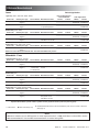
Offshore Manufactured
Isuzu
Vehicle Application
Light Duty ("NPR", "NPR-HD", "NQR", "NRR")
Model Year
Brake System Type
1986-1998
Dual
(Figure 2)
2000-2013
4-channel ABS
(Figure 7)
Medium Duty (Isuzu "FRR")
Model Year
Brake System Type
Interlock Applications /
Aerial Lift Bucket
Service Brakes Miscellaneous Notes
Disc/Drum-Drum Vacuum/Hydraulic.
F-disc/R-drum
Vacuum/Hydraulic
or Hydraulic/Hydraulic.
Service Brakes Miscellaneous Notes
1988-1998
Dual
(Figure 2)
Drum
2000-2004
3-channel ABS
(Figure 5)
4 wheel drum
Other Applications
4 Wheel
2 Wheel
4 Wheel
2 Wheel
02-691-209
02-691-109
02-691-209
02-640-169
02-691-109
02-640-023
02-691-403
02-691-209
02-691-403
02-691-209
02-640-169
4 Wheel
2 Wheel
4 Wheel
2 Wheel
Air/Hydraulic.
02-691-209
02-691-109
02-691-209
02-640-169
02-691-109
02-640-023
Air/Hydraulic boost
with ABS on the air side.
02-691-303
02-691-209p 02-691-303
02-691-209p
02-640-169p
Medium Duty (Isuzu "FSR", "FTR", "FVR")
Model Year
Brake System Type
Service Brakes Miscellaneous Notes
4 Wheel
1999-2010
4-channel ABS
4-wheel disc
Hydraulic booster.
02-691-403
(Figure 7)
NOTE: For Isuzu H-Series conventional cabs - See Chevrolet Medium duty section.
2 Wheel
4 Wheel
2 Wheel
02-691-209
02-691-403
02-691-209
02-640-169
Mitsubishi - Fuso
Light-Medium Duty (FE-FG, 125-180)
Model Year
Brake System Type
1991-1998
Dual
(Figure 2)
2000-2013
4-channel ABS
(Figure 7)
Medium Duty (FH)
Model Year
Brake System Type
Service Brakes Miscellaneous Notes
Drum
F-disc/R-drum, Vacuum/Hydraulic
4-wheel disc,
booster.
or 4-wheel drum
Service Brakes Miscellaneous Notes
4 Wheel
2 Wheel
4 Wheel
2 Wheel
02-691-209
02-691-109
02-691-209
02-640-169
02-691-209
02-640-023
02-691-403
02-691-209
02-691-403
02-691-209
02-640-169
4 Wheel
2 Wheel
4 Wheel
2 Wheel
1996-1998
Dual
(Figure 2)
4-wheel drum
Air/Hydraulic boosters.
02-691-201¨ 02-691-101¨ 02-691-201¨ 02-691-101¨
02-640-169 02-640-023
2000-2004
4-channel ABS
(Figure 7)
4-wheel drum
Hydraulic booster.
02-691-403
02-691-209
02-691-403
02-691-209
02-640-169
4 Wheel
2 Wheel
4 Wheel
2 Wheel
Medium Duty (FK, FM-MR, FM-HR, FM260)
Model Year
Brake System Type
Service Brakes Miscellaneous Notes
1991-1998
Dual
(Figure 2)
4-wheel drum
1999-2010
3-channel ABS
(Figure 5)
4-wheel drum
02-691-201¨ 02-691-101¨ 02-691-201¨ 02-691-101¨
02-640-169 02-640-023
3-channel ABS
Air/Hydraulic boost
with ABS on air side.
02-691-303
02-691-209p 02-691-303
02-691-209p
02-640-169p
NOTE: Vacuum/Hydraulic Boost = Vacuum assisted booster for hydraulic cylinder
Hydraulic Boost Master Cylinder = Master cylinder driven by hydraulic booster powered by steering pump
Best Choice
p Rear wheel lockup only.
¨ 02-600-038 Remote Reservoir Kit recommended if power unit is mounted on frame rail.
(See page 14)
NOTE
1999 was a transition year to ABS systems on most imported trucks. If a 1999 model does not have ABS, use the
1998 recommendations. Use the 2000 recommendations for trucks having ABS.
12
MICO, Inc.
Form No. 80-950-152
Revised 2012-12-14
Offshore Manufactured
UD
Vehicle Application
Light Duty (1200-1400)
Interlock Applications /
Aerial Lift Bucket
Model Year
Brake System Type
1990-1998
Dual
(Figure 2)
4-wheel drum
2000-2012
4-channel ABS
(Figure 7)
F-disc/R-drum,
or 4-wheel disc
Medium Duty (1800-2600)
Model Year
Brake System Type
Service Brakes Miscellaneous Notes
Other Applications
4 Wheel
2 Wheel
4 Wheel
2 Wheel
Vacuum/Hydraulic
booster.
02-691-209
02-691-109
02-691-209
02-640-169
02-691-109
02-640-023
Vacuum/Hydraulic
booster.
02-691-403
02-691-209
02-691-403
02-691-209
02-640-169
4 Wheel
2 Wheel
4 Wheel
2 Wheel
Service Brakes Miscellaneous Notes
1990-1998
Dual
(Figure 2)
4-wheel drum
Air/Hydraulic boosters.
On trucks with optional
air-rear parking brake,
lock front brakes only.
02-691-201¨ 02-691-101¨ 02-691-201¨ 02-691-101¨
02-640-169 02-640-023
2000-2013
4-channel ABS
(Figure 7)
4-wheel drum
Air/Hydraulic boosters.
On trucks with optional
air-rear parking brake,
lock front brakes only.
02-691-403
02-691-209
02-691-403
02-691-209
02-640-169
NOTE: Vacuum/Hydraulic Boost = Vacuum assisted booster for hydraulic cylinder
Hydraulic Boost Master Cylinder = Master cylinder driven by hydraulic booster powered by steering pump
Best Choice
¨ 02-600-038 Remote Reservoir Kit recommended if power unit is mounted on frame rail.
(See page 14)
NOTE
1999 was a transition year to ABS systems on most imported trucks. If a 1999 model does not have ABS, use the
1998 recommendations. Use the 2000 recommendations for trucks having ABS.
MICO, Inc.
Form No. 80-950-152
Revised 2012-12-14
13
691 Accessories
Remote Reservoir
Elbow Fittings and Straight Adapters
For use in (BF) applications
Simplify plumbing installation using 90° or 45° elbows
and straight adapters available from MICO. These
fittings allow more direct routing of brake tubes with
fewer bends and are handy when mounting components in close quarters.
MICO offers a remote reservoir kit (part number
02-600-038) for installations where the Power Unit
brass breather plug cannot be kept upright and away
from dust and dirt or when visual monitoring of fluid
level is desired.
34-350-006 90° Elbow
34-350-011 45° Elbow
7/16-20UNF
37o Flare
7/16-20UNF
37o Flare
Remote Reservoir Kit
(part number 02-600-038 includes items below)
7/16-20UNF
7/16-20UNF
34-050-078 Straight Adapter
34-050-079 Straight Adapter
SAE 7/16-24
for 1/4" Line
SAE 3/8-24
for 3/16" Line
Reservoir
7/16-20UNF
37o Seat
Connector
7/16-20UNF
37o Seat
Wire Harness Extension
Tubing, 10 ft.
The 11 ft. supplemental harness simplifies wiring
when 691 Control Module is mounted away from
Power Unit. Contains waterproof adapters for quick
connection of Control Module and Power Unit leads.
Part number 32-820-022.
Connector
Adapter
Nut
691 Models and Sub-Components
System
Model
Number
Description
Power Unit
Control
Module
Actuator
User
Interface
Main
Wire
Harness
02-691-101
Single (1 3/4 in. bore)
20-410-014
32-585-006
20-460-013
32-585-007
32-820-021
02-691-109
Single (1 1/4 in. bore)
20-410-014
32-585-006
20-460-018
32-585-007
32-820-021
02-691-201
Dual (1 3/4 in. bore)
20-410-014
32-585-006
20-460-012
32-585-007
32-820-021
02-691-209
Dual (1 1/4 in. bore)
20-410-014
32-585-006
20-460-017
32-585-007
32-820-021
**
02-691-223
Dual (1 1/4 in. bore)
20-410-014
32-585-006
20-460-018 (two)
32-585-007
32-820-021
***
02-691-303
3-Channel
20-410-014
32-585-006
20-460-013 (one)
20-460-017 (one)
32-585-007
32-820-021
**** 02-691-305
3-Channel
20-410-014
32-585-006
20-460-018 (one)
20-460-017 (one)
32-585-007
32-820-021
***** 02-691-403
4-Channel
20-410-014
32-585-006
20-460-017 (two)
32-585-007
32-820-021
**
***
****
*****
14
Consists of two 1 1/4 inch diameter single actuators.
Consists of one 1 3/4 inch diameter single actuator and one 1 1/4 inch diameter dual actuator.
Consists of one 1 1/4 inch diameter single actuator and one 1 1/4 inch diameter dual actuator.
Consists of two 1 1/4 inch diameter dual actuators.
MICO, Inc.
Form No. 80-950-152
Revised 2012-12-14
1.
2.
3.
4.
5.
6.
7.
8.
9.
10.
11.
12.
13.
14.
MICO, Inc.
Form No. 80-950-152
All MICO locking devices are supplemental safety equipment which provide
additional brake holding action when used with existing vehicle parking
brake.
The Low Pressure Warning Switch must be used in combination with an
audible and/or visual alarm to signal any loss of system pressure. The Low
Pressure Warning Switch is explained in the Operating Instructions. Do not
disconnect Low Pressure Warning Switch. (Does not apply for 691 Brake
Lock System).
The 691 System must be used in combination with an audible and/or visual
alarm to signal any loss of brake system pressure. Do not disconnect vehicle
horn/visual alarm or Control Module alarm.
All lines, fittings and adjacent areas must be cleaned of dirt or road residue
before any lines or fittings are disconnected. Special care should be taken so
dirt and road residue are not allowed to enter hydraulic brake system. This
could contaminate the system and interfere with proper operation of brakes
and MICO locking devices.
Follow procedures outlined in Vehicle Manufacturer’s Service Manual or SAE
Standards when making new connections or adding to existing brake systems.
Use only steel brake tubing conforming to SAE specifications.
Use only proper system fluid conforming to latest SAE or DOT Standards. Improper or contaminated fluid may cause gummy deposits and softening and
swelling of other rubber seals in the entire brake system. Such a condition
must be corrected immediately.
Do not use sealants, tapes, teflon or cement compounds on any connections
or fittings. The sealants or compounds can contaminate the hydraulic brake
system and interfere with the operation of brake components or MICO locking
device.
All fittings and connections must be in good condition and tightened to proper
torque values as specified in the Installation and Service Instructions.
Separate models of MICO locking devices are available for brake fluid and for
mineral based hydraulic oil. Select model to conform with the type of fluid in
system.
Brake hoses, brake lines, MICO locking device, brake components, cylinders,
and all fittings must be routinely inspected for leaks, damage or wear. Adequate fluid levels must be maintained. In the event of any loss of fluid, brake
system must be carefully inspected for leaks.
After installation, bleed system according to vehicle manufacturer’s recommendations.
Follow INSPECTIONS and TESTS section as outlined in the Operating
Instructions.
The self-adhesive warning(s) accompanying each MICO locking device must
be affixed in cab in view of operator.
The Operating Instructions must be placed in cab of vehicle in a place available to operator.
Revised 2012-12-14
15
MICO could not possibly know of and give advice with respect to all conceivable applications in which these products might be used and the possible hazards
and/or results of each application. MICO has not undertaken any such wide evaluation. Therefore, anyone who uses an application which is not recommended by
the manufacturer, first must completely satisfy himself that a danger will not be created by the application selected, or by the particular model of our product that is
selected for the application.
MICO has made every attempt to present accurate information in catalogs, brochures and other printed material. MICO can accept no responsibility for errors
from unintentional oversights that may exist. Due to a continuous program of product improvement, materials, specifications, and product documentation are
subject to change without notice or obligation.
MICO is a trademark and registered trademark of MICO, Inc. MICO is registered in the U.S. Patent and Trademark Office as well as in Australia, Canada, Indonesia, Japan, Peoples Republic of China, South Korea, and the European Community.
MICO, Incorporated
Innovative Braking and Controls Worldwide
Form No. 80-950-152
Revised 2012-12-14
1911 Lee Boulevard
North Mankato, MN U.S.A. 56003-2507
Tel: +1 507 625 6426 Fax: +1 507 625 3212
www.mico.com