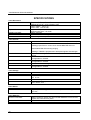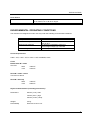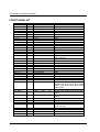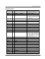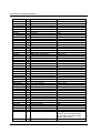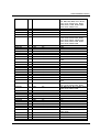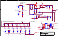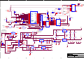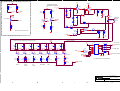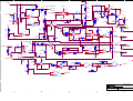
1
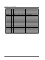
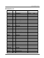
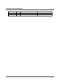
Polar Instruments Ltd.
Garenne Park
St. Sampson
Guernsey
Channel Islands
GY2 4AF
ENGLAND
http://www.polar.co.uk
Fax: +44 (0)1481 252476
Email: [email protected]
MAN130–2011
TONEOHM 950
SERVICE
MANUAL
TONEOHM 950 SERVICE MANUAL
POLAR INSTRUMENTS LTD. HARDWARE WARRANTY
1.
Product Warranty. Product hardware is warranted to be free from defects in material and
workmanship during the Warranty Period (as defined below). Product hardware is warranted to
conform substantially to Polar’s then current (as of the date of Polar’s product shipment)
published user documentation during the Warranty Period. The Warranty Period is twelve (12)
months. Product support beyond these periods may be available at additional cost – consult Polar
for details.
2.
Warranty Claims. Polar shall incur no liability under this warranty if the end user fails to provide
Polar with notice of the alleged defect during the applicable Warranty Period and within seven (7)
days of delivery to end user or, if the defect would not have been reasonably apparent on
inspection, within seven (7) days of its discovery by end user. After receiving such notice, Polar
will notify the purchaser of its designation of one of the following problem resolution methods:
Return to Factory: The allegedly defective goods must be returned to Polar within seven
days of Polar’s notice and in accordance with Polar’s instructions advised at the time.
Other: Polar will use commercially reasonable efforts to repair, correct or work around
the problem by means of telephone support or other means reasonably determined by
Polar.
Polar shall incur no liability under this warranty if Polar’s tests disclose that the alleged defect is
due to causes not within Polar’s reasonable control, including alteration or abuse of the goods.
Under the Return to Factory alternative, if a Product is determined not to be defective or to have a
defect due to causes not within Polar’s reasonable control, Polar reserves the right to apply a
processing charge.
3.
Damage in Transit. End user must notify Polar and the carrier of any claim for damage in transit
within two (2) days of receipt of the damaged merchandise. Failure to do so may result in the
carrier and/or Polar refusing to accept liability in which case end user must pay the purchase price
as if the hardware had been delivered without damage.
4.
Polar’s Liability Polar’s liability, and end user’s sole and exclusive remedy, shall be limited to the
express remedies set forth in this Polar Hardware Warranty.
5.
Disclaimer of Warranties. POLAR MAKES NO OTHER WARRANTIES, EXPRESS, IMPLIED
OR STATUTORY, REGARDING PRODUCTS. ALL OTHER WARRANTIES AS TO THE
QUALITY, CONDITION, MERCHANTABILLITY, FITNESS FOR A PARTICULAR PURPOSE,
OR NON-INFRINGEMENT ARE EXPRESSLY DISCLAIMED.
6.
Limitation of Liability. POLAR SHALL NOT BE RESPONSIBLE FOR DIRECT DAMAGES IN
EXCESS OF THE PURCHASE PRICE PAID BY THE END USER OR FOR ANY SPECIAL,
CONSEQUENTIAL, INCIDENTAL, OR PUNITIVE DAMAGE, INCLUDING, BUT NOT LIMITED
TO, LOSS OF PROFITS OR DAMAGES TO BUSINESS OR BUSINESS RELATIONS,
WHETHER OR NOT ADVISED IN ADVANCE OF THE POSSIBILITY OF SUCH DAMAGES,
THE FOREGOING LIMITATIONS SHALL APPLY, NOTWITHSTANDING THE FAILURE OF
ANY EXCLUSIVE REMEDIES.
DECLARATIONS
DECLARATIONS
European Community Directive Conformance Statement
Refer to the Operator Manual to determine conformance with European
Community Directives.
v
TONEOHM 950 SERVICE MANUAL
SAFETY
WARNING The service instructions contained in this manual are for use
by qualified electronic service personnel only.
WARNING
The LIVE and NEUTRAL lines on this unit are BOTH fused.
When the unit is connected to its supply, the opening of covers or removal of panels is likely to expose
dangerous voltages.
GROUNDING
This unit must be earthed (grounded); do not operate the instrument with the safety earth disconnected.
Ensure the instrument is connected to an outlet with an effective protective conductor terminal (earth). Do
not negate this protective action by using an extension cord without a protective conductor.
Note: This instrument is fitted with 3-wire grounding type plug designed to fit only into a grounding type
power outlet. If a special local plug must be fitted to the power cord ensure this operation is performed by
a skilled electronics technician and that the protective ground connection is maintained. The plug that is
cut off from the power cord must be safely disposed of.
Power cord color codes are as follows:
Europe
brown
blue
green/yellow
live
neutral
earth (ground)
United States
black
white
green
live
neutral
ground
POWER SUPPLY
Check that the indicated line voltage setting corresponds with the local mains power supply. See the rear
panel for line voltage settings. Instruments with a serial number prefixed with a letter (e.g. A1234) are
configured for 90 – 110 Volts only.
Changing the line voltage settings on this instrument must only be performed by a skilled electronics
technician. Instructions for changing the line voltage settings are contained in Section 5.
vi
SAFETY
OPERATION
This manual contains instructions and warnings which must be observed by the user to
ensure safe operation. Operating this instrument in ways other than detailed in this
manual may impair the protection provided by the instrument and may result in the
instrument becoming unsafe. Retain these instructions for later use.
The unit is designed for use indoors in an electrical workshop environment at a stable work station
comprising a bench or similar work surface.
Use only the accessories (e.g. test probes and clips) provided by Polar Instruments.
The instrument must be maintained and repaired by a skilled electronics technician in accordance with the
manufacturer’s instructions.
If it is likely that the protection has been impaired the instrument must be made inoperative, secured
against unintended operation and referred to qualified service personnel.
Protection may be impaired if, for example, the instrument:
•
•
•
•
•
Shows signs of physical damage
Fails to operate normally when the operating instructions are followed
Has been stored for prolonged periods under unfavourable conditions
Has been subjected to excessive transport stresses
Has been exposed to rain or water or been subject to liquid spills
CAUTION
Electrical Isolation
Always disconnect the board under test from the local mains supply (including ground) before using this
instrument.
Static Sensitive Devices
This unit contains Static Sensitive Devices. Static discharge can damage some electronic components.
Care must be taken when handling these components. Observe appropriate precautions to avoid damage.
vii
TONEOHM 950 SERVICE MANUAL
SPECIFICATIONS
Track Resistance
RANGES
ACCURACY
[Ω] RANGE
PROBE VOLTAGE
INDICATION
PROBE PROTECTION
Track Current
RANGES
ACCURACY
[Ω], 200mΩ, 2Ω, 200Ω, 20KΩ. Instruments with serial numbers below
005975 have a 2KΩ range instead of 200Ω.
±6% in 200mΩ, ±5% in 2Ω
±4% in 200Ω, ±5% in 20KΩ
High sensitivity, uncalibrated.
Approximately 40mΩ full scale.
60mV maximum.
Tone and meter in all ranges.
Momentary contact up to 250V.
200mA, 2A, TRACE.
±15% in 200mA, 2A for track resistance between 25mΩ and 500mΩ.
Reading proportional to current when UNCALIBRATED LED is lit.
UNCALIBRATED LED lit during ranging.
TRACE SENSITIVITY
PROBE VOLTAGE
INJECTION CURRENT
INDICATION
PROBE PROTECTION
Track Voltage
RANGES
ACCURACY
INPUT RESISTANCE
INDICATION
PROBE PROTECTION
Plane Shorts
INDICATION
SENSITIVITY
Plane Stimulus
OUTPUT VOLTAGE
OUTPUT CURRENT
PROTECTION
viii
Reading in TRACE is proportional to detected magnetic field strength.
Capable of detecting current flow with 200Ω resistance across Drive
Source.
600mV maximum in 200mA, 2A.
Not applicable in TRACE.
250mA maximum.
Not applicable in TRACE.
Tone and meter in all ranges.
Momentary contact up to 250V in 200mA, 2A.
Not applicable in TRACE.
2mV, 20mV, 20V.
±4%, ±15µV.
120Ω in 2mV, 20mV.
1MΩ in 20V.
Meter in all ranges. Tone in 2mV, 20mV.
Momentary contact up to 250V in 20V.
30V in 20mV, 2mV.
Tone, uncalibrated meter and fault direction arrows.
Adjustable for differing plane resistance. Capable of detecting shorts
up to 20Ω.
550mV maximum. Active only when PLANE SHORTS is ACTIVE and
outputs are connected to a plane.
700mA RMS maximum.
Each output separately fused (5A Fast).
SPECIFICATIONS
Drive Source
OUTPUT VOLTAGE
0 to 550mV, adjustable.
AC in TRACE, DC in all other ranges.
Protected to ± 30V.
PROTECTION
ENVIRONMENTAL OPERATING CONDITIONS
The instrument is designed for indoor use only under the following environmental conditions:
Altitude
Temperature
Relative humidity
Mains borne transients
Pollution Degree
Up to 2000m
+5°C to +40°C ambient
RH 80% maximum at 31°C — derate linearly to
50% at 40°C
As defined by Installation Category II
(Overvoltage Category II) in IEC664
2 (IEC664)
Power Requirements
230V ± 10%, 115V ± 10% or 100V ± 10% at 50/60Hz, 25VA.
Fuses
Below Serial Nº. 11244
One fuse
230V
115V
160mAT
315mAT
Serial Nº. 11265 – 12212
Two fuses as above
Serial Nº. 12213 up
230V
115V
125mAT
250mAT
Physical characteristics (excluding accessories)
Dimensions
305mm (12 in.) wide.
150mm (5.9 in.) high.
275mm (10.8 in.) deep.
Weight
3.5 kg.
Flammability
Enclosure to UL94 V-0.
ix
TONEOHM 950 SERVICE MANUAL
SYMBOLS
REFER TO MANUAL
These sockets are for connecting only Polar Instruments probes and
connectors for use as described in the Operator Manual. To prevent
damage to this product and to ensure its safe use observe the
specifications given in this manual when connecting to terminals
marked with this symbol.
ACCESSORIES
Standard Accessories
Needle Probes
950 Plane Probe/Clip assembly
950 Current Trace Probe assembly
950 Stimulus Lead (Set of 4)
Lightweight Headphones
ACC152
ACC113
ACC114
ACC134
EPM115
Optional Accessories
Bare-board Stimulus Lead set (0.025")
Bare-board Stimulus Lead set (0.031")
Bare-board Stimulus Lead set (0.040")
Bare-board Lead set (universal)
Service Manual
x
ACC121/XG25
ACC121/XG31
ACC121/XG40
ACC154
MAN130
CONTENTS
CONTENTS
DECLARATIONS.......................................................................................................................................... v
European Community Directive Conformance Statement .....................................................................v
SAFETY ....................................................................................................................................................... vi
WARNING.................................................................................................................................................vi
GROUNDING ............................................................................................................................................vi
POWER SUPPLY .....................................................................................................................................vi
OPERATION ............................................................................................................................................ vii
CAUTION ................................................................................................................................................. vii
Electrical Isolation............................................................................................................................. vii
Static Sensitive Devices ....................................................................................................................... vii
SPECIFICATIONS ..................................................................................................................................... viii
ENVIRONMENTAL OPERATING CONDITIONS .....................................................................................ix
Power Requirements.............................................................................................................................ix
Fuses.....................................................................................................................................................ix
Physical characteristics (excluding accessories) ..................................................................................ix
SYMBOLS ................................................................................................................................................. x
ACCESSORIES ........................................................................................................................................ x
Standard Accessories ........................................................................................................................... x
Optional Accessories............................................................................................................................. x
SECTION 1 PERFORMANCE CHECK ..................................................................................................... 1-1
MAINTENANCE AND CALIBRATION OF INSTRUMENTS .................................................................. 1-1
Performance Check ........................................................................................................................... 1-1
Adjustment Procedure........................................................................................................................ 1-1
Recommendations for Routine Maintenance ..................................................................................... 1-1
PERFORMANCE CHECK...................................................................................................................... 1-2
Equipment required ............................................................................................................................ 1-2
Procedure........................................................................................................................................... 1-2
SECTION 2 – ADJUSTMENT PROCEDURE ........................................................................................... 2-1
ADJUSTMENT PROCEDURE ............................................................................................................... 2-1
Equipment required ............................................................................................................................ 2-1
Display Calibration.............................................................................................................................. 2-1
A2D Calibration .................................................................................................................................. 2-1
Resistance Calibration ....................................................................................................................... 2-1
Current range adjustment .................................................................................................................. 2-2
Current offset calibration — Version 8 firmware and above............................................................... 2-2
Current Trace ..................................................................................................................................... 2-2
Plane Shorts ....................................................................................................................................... 2-3
SECTION 3 – CIRCUIT DESCRIPTION.................................................................................................... 3-1
TONEOHM 950 THEORY OF OPERATION. ........................................................................................ 3-1
Main Operating modes. ...................................................................................................................... 3-2
Track resistance ............................................................................................................................. 3-2
Track Current ................................................................................................................................. 3-2
Trace .............................................................................................................................................. 3-2
Track Voltage ................................................................................................................................. 3-2
xi
TONEOHM 950 SERVICE MANUAL
Plane Shorts ................................................................................................................................... 3-2
Detailed Theory of operation. ............................................................................................................. 3-3
Microvolt Amplifier .......................................................................................................................... 3-3
Trace Amplifier ............................................................................................................................... 3-3
Current Source ............................................................................................................................... 3-3
Plane Amplifier and Vector Discriminator....................................................................................... 3-3
Vectored Plane Stimulus ................................................................................................................ 3-4
Drive Source................................................................................................................................... 3-5
Tone Generator .............................................................................................................................. 3-5
A2D2A ............................................................................................................................................ 3-5
Power Supply. ................................................................................................................................ 3-5
Microprocessor............................................................................................................................... 3-6
Front Panel (Schematics 1 and 2).................................................................................................. 3-6
SECTION 4 – DISMANTLING INSTRUCTIONS ....................................................................................... 4-1
Removing the cover ........................................................................................................................... 4-1
SECTION 5 – LINE VOLTAGE AND FUSE CHANGING.......................................................................... 5-1
LINE VOLTAGE SELECTION AND FUSE CHANGING ........................................................................ 5-1
Changing the line voltage setting ....................................................................................................... 5-1
SECTION 6– FAULT DIAGNOSIS ............................................................................................................ 6-1
TROUBLESHOOTING HINTS ............................................................................................................... 6-1
SECTION 7 – MAINTENANCE AND CLEANING ..................................................................................... 7-1
Cleaning ............................................................................................................................................. 7-1
Technical Support .............................................................................................................................. 7-1
Instrument repair ................................................................................................................................ 7-1
SECTION 8 – REPLACEMENT PARTS.................................................................................................... 8-1
FRONT PANEL KIT ............................................................................................................................... 8-2
MAIN BOARD KIT .................................................................................................................................. 8-3
MECHANICAL KIT ................................................................................................................................. 8-7
SECTION 9 – SCHEMATIC DIAGRAMS .................................................................................................. 9-1
xii
SECTION 1 PERFORMANCE CHECK
MAINTENANCE AND CALIBRATION OF INSTRUMENTS
For most of Polar Instruments’ products there are two maintenance procedures — the Performance
Check and the Calibration. Some instruments may have a single (combined) procedure.
Performance Check
The Performance Check (or Checkout Procedure) is used to verify the basic functions of the instrument.
This does not usually require the removal of instrument covers, but may require the use of external test
equipment. This procedure is not intended to verify the calibration of the instrument.
Adjustment Procedure
The Adjustment Procedure (or Calibration Procedure) is used to check and, if necessary, adjust the
instrument’s calibration settings. Before carrying out the Adjustment Procedure the instrument’s
Performance Check (if applicable) should be carried out, and any detected defects should be rectified.
The Adjustment Procedure and rectification of defects should only be carried out by qualified technician.
Recommendations for Routine Maintenance
Where a Performance Check is available for an instrument this may be used as required to confirm the
basic operation of the product.
To maintain the calibration of an instrument it is recommended that its Calibration/Adjustment Procedure
is carried out at intervals not exceeding 12 months.
1-1
TONEOHM 950 SERVICE MANUAL
PERFORMANCE CHECK
Equipment required
•
DC voltage source, variable from 1V to 10V and accurate to 0.1%.
•
High tolerance resistors (0.5%) of the following values: 10KΩ, 1KΩ (serial numbers
below 005975 only), 200Ω, 100Ω, 1Ω and 0.1Ω.
Procedure
• Switch on and allow the 950 to warm up for 15 minutes.
1. Plug in the Needle Probes and press 20V.
2. Apply 10V DC to the probes and check that the reading is 10V ± 4%.
3. Connect a 1KΩ 0.5% and a 1Ω 0.5% resistor in series.
4. Apply 10V to the series resistors. This produces 10mV across the 1Ω Resistor.
5. Press 20mV and check that the reading across the 1Ω resistor is 10mV ± 4%.
6. Adjust the voltage source from 0 to 20V and check that the tone varies in pitch. A
steady warble should be generated with a negative voltage.
7. Apply 1V to the two resistors and press 2mV.
8. Check that the reading across the 1Ω resistor is 1mV ± 4%.
9. Check that varying the voltage generates varying tones. No tone should be produced
below about 50uV.
10. Press 20KΩ and measure a 10KΩ 0.5% resistor. The reading should be within 4%. A
warble may be generated in this range.
(a) Serial numbers below 005975:
Press 2KΩ and measure a 1KΩ 0.1% resistor. The reading should be within 4%.
(b) Serial numbers 005975 up:
Press 200Ω and measure a 100Ω 0.1% resistor. The reading should be within 4%.
11. Press 2Ω and measure a 1Ω 0.1% resistor. The reading should be within 4%.
12. Apply solder to the wire ends of a 100mΩ 0.5% resistor.
13. Press 200mΩ and measure the resistor by pressing the probe tips into the solder.
The reading should be within 4%. Readings vary with the pressure applied to the
probes.
14. Press TRACE and connect the Drive Source leads across a 200 Ω resistor. Turn the
DRIVE SOURCE knob fully clockwise.
15. Hold the Current Trace Probe tip near to one of the Drive Source leads and align it
for maximum response.
16. Check that the display shows 20 or more.
17. Connect the Blue and Yellow Stimulus lead together. Press PLANE twice — check
for the warning bell and that the instrument returns to Standby. Leave leads
connected.
18. Connect the Red and Green Stimulus lead together. Press PLANE once. Check for
ACTIVE LED.
19. Connect the red and black Drive Source leads across a 0.1Ω resistor. Attach the
Plane Clip to the black Drive Source lead. Probe the other end of the resistor with the
probe.
1-2
PERFORMANCE CHECK
20. Slowly turn the DRIVE SOURCE from minimum to maximum (i.e. clockwise). As the
control is rotated, check that initially all direction arrow LEDs are on, then the upper
LED only, then all LEDs are off. At the same time the tone goes from high to low then
off.
21. Reverse the connections to the Plane Probe and Clip. Rotate DRIVE SOURCE from
maximum to minimum (i.e. anti-clockwise). As the control is rotated, check initially for
no arrows or tone, then rising tone and bottom arrow on, finally all arrows on.
22. Disconnect the Red and Green Stimulus lead. PLANE should automatically ring
warning bell and return to standby. Disconnect the Plane Probe and Clip from the
0.1Ω resistor.
23. Turn DRIVE SOURCE to maximum. Select 20mV, connect the Needle Probes and
drive source leads across the 0.1Ω Resistor and note reading.
24. Select 200mA. Check that reading is: (10x Reading noted above) ±10%
25. Turn DRIVE SOURCE to minimum. Check for 0 ±1mA.
26. Disconnect all cables.
1-3
SECTION 2 – ADJUSTMENT PROCEDURE
ADJUSTMENT PROCEDURE
WARNING: Hazardous voltages are exposed on the PCB when the cover is removed.
This procedure should only be performed by a technically qualified person aware of the
hazards and taking all reasonable care.
Equipment required
•
High tolerance(0.1%) voltage source — 10V and 10mv.
•
High tolerance(0.1%) 1Ω and 100mΩ resistors.
•
DVM
•
Power Supply.
Before connecting to the supply:–
1. CHECK THE MAINS FUSES — see SPECIFICATIONS.
2. Connect the 950 to the appropriate line voltage and turn on.
3. CHECK the front panel lights sequence and that the 950 stops in the 20V range.
PUSH 20mV.
Display Calibration
1. Connect the Needle Probes to the 10mV source.
2. Adjust POT R196 (top RHS of Front Panel board) for a display of 10.00mV.
A2D Calibration
1. Turn the power off then hold down 2mV and PLANE — re-apply power.
2. Connect needle probes to 10mV source.
3. Observe the Active and Standby (Pass and Fail) LEDs while adjusting R163 — the
tone will decrease as the calibrated position is approached.
When ACTIVE illuminates the A2D is calibrated.
4. PUSH 2mV. The 950 will beep and enter the 20V Range.
Resistance Calibration
1. SELECT the 2Ω range. Place the probes across the 1Ω resistor. ADJUST R713 (R30
for instruments below S/N 012213) for 1.000Ω reading ± 3 Counts.
2-1
TONEOHM 950 SERVICE MANUAL
Current range adjustment
(Serial Nº. 012213 and above — below this Serial Nº. there is no adjustment.)
1. Select the 200mA range. Drive source control fully clockwise.
2. Connect the drive source and the DVM across the high tolerance 1Ω resistor.
3. Note the DVM reading.
4. Apply the needle probes across the resistor and adjust R 30 for the same reading as
the DVM ± 5 counts.
Current offset calibration — Version 8 firmware and above
1. Set the current limit to MINIMUM — switch the supply ON.
2. Select 2A on the 950.
3. Connect the power supply across the 100mΩ resistor.
4. Adjust the current limit to 1.6A.
5. Using the Needle Probes measure across the 100mΩ resistor CHECK for 1.44 to
1.76A on the 950 display.
(Version 8 firmware and above, main board version 5 and above.)
Select the most accurate 1.6A reading by optionally placing a jumper on one of the 4
locations adjacent to U46.
No jumper is the mid setting, H fixes slight under-reading, HH corrects large underreading. L fixes slight over-reading, and LL corrects large over-reading.
(Version 8 firmware, main board version 4 or below.)
Connect a 20 way integrated circuit test clip to U46
Shorting Pin 17 to Gnd corresponds to HH
14
H
13
LL
8
L
No connection is nominal setting.
Once the best setting is established solder a link from the appropriate pin (if any ) to
ground.
6. Version 7 firmware and below offer no fine adjustment.
Current Trace
1. Connect Trace / Drive Source Probe.
2. Push TRACE. Adjust the volume as desired, short the drive source leads together
and turn the drive source to MAXimum.
3. While holding the probe against the Drive Source lead ADJUST R94 for the highest
displayed reading (> 500).
Move the probe away from the Drive Source leads,
4. CHECK Tone turns off and displayed reading is less than 25.
2-2
ADJUSTMENT PROCEDURE
Plane Shorts
1. CONNECT the 4 Plane Stimulus leads BLUE to YELLOW and RED to GREEN
2. Push PLANE twice to enter ACTIVE mode.
3. CONNECT the Plane Clip to the Plane Probe. Adjust R85 for a reading of 00.0 ± 3
counts.
(Ser Nº 012213 up)
Adjust R716 (located near U18, behind copper shield) for minimum (or most
negative) reading.
Re-adjust R85 for 00.0 ± 3 counts.
4. Reduce the Variac to:
190V (240V instruments)
95V (120V instruments)
85V (Japanese instruments)
5. Check that PLANE remains ACTIVE
6. Remove the Green clip from the demo board and check the 950 goes to standby.
Reconnect the clip and select ACTIVE.
7. Repeat for the yellow clip.
8. Disconnect all probes.
2-3
SECTION 3 – CIRCUIT DESCRIPTION
TONEOHM 950 THEORY OF OPERATION.
The TONEOHM 950 consists of the following functional blocks.
1. Microvolt Amplifier
Amplifies/attenuates PCB track voltages, and is used in
conjunction with the internal current source for the
calculation of track resistance and current.
2. Trace Amplifier
Amplifies and rectifies the low level AC signal from the
Trace probe to provide a DC voltage output proportional
to magnetic field.
3. Current source
Provides a range of currents for resistance and noninvasive current measurement.
4. Plane Amplifier and
Vector discriminator
Amplifies low level plane signals, separates vector and
magnitude components.
5. Vectored Plane Stimulus
Provides the four vectored signals for Plane Shorts
mode.
6. Drive Source
User adjustable constant current DC supply for noninvasive current measurement/
µV measurement.
Also operates in a.c. for non-contact current tracing.
7. Tone Generator
Voltage controlled oscillator which provides varying tone
proportional to meter reading.
8. A2D2A
Analog to digital convertor used for providing
microprocessor with data for non-invasive current
measurement, also used for internal calibration and QC.
Digital to analog converter provides output for tone
generator in 2A and 200mA modes and output to front
panel meter.
9. Power Supply
10. Microprocessor
± 5V analog and digital supplies.
12/5V floating supply for drive source.
4V a.c. supply for vectored plane stimulus.
Controls hardware and performs current calculation.
11. Front Panel
Keyboard and display D2A.
3-1
TONEOHM 950 SERVICE MANUAL
Main Operating modes.
Track resistance
Current is injected into the track with the needle probes using the CURRENT SOURCE module, the µV
AMPLIFIER conditions the resulting track voltage and displays the result directly on the LCD.
Track Current
200mA, 2A.
These ranges compute the current by measuring the voltage drop across a length of track carrying the
fault current and then injecting a known current in addition to the fault current. The voltage drop is then remeasured and the resistance calculated hence the fault current can be derived.
e.g.
Track Resistance =
V due to fault I – (V due to fault I + V due to injected I)
Injected I
V due to fault I
Hence Fault Current = Track Resistance
The 950 first reads the track voltage with the µV AMPLIFIER and uses the A2D2A to digitise the value.
The amplifier auto-ranges if necessary, then a small current is injected from the CURRENT source, the
track voltage is read again, if the second voltage is not significantly different (<10% higher) the 950 injects
more current. This process reiterates up to a maximum of 240mA injection at which point the
microprocessor will force a calculation and send the resultant value to the D2A. This is sent both to the
front panel meter and via the conditioning network on U59 (Schematic 1) to the TONE GENERATOR.
During the initial ranging and for on track resistances below approximately 25mΩ the un-calibrated
indicator will illuminate. Once ranging has taken place the initial injection/ attenuation settings are held
and the current is calculated continuously. The 950 will only measure positive conventional current. If the
probes are reversed the condition will be indicated on the front panel and the display will blank.
Trace
In TRACE mode the 950 uses an inductive pick up to detect an ac current in a faulty track. The ac current
is supplied from the DRIVE SOURCE leads, the detected signal is conditioned by the TRACE amplifier
and then switched to the LCD and TONE GENERATOR by U25 (sheet 6) and U59 (sheet 1) respectively.
Track Voltage
The µV AMPLIFIER conditions the track voltage and sends it to the LCD via U25 (sheet 6) and to the
TONE GENERATOR. The tone is disabled on the 20V range.
Plane Shorts
In Plane Shorts mode the 950 uses VECTORED PLANE Stimulus to set up a field pattern on the plane
under test, the Plane Clip references the short to ground and the voltage measured on the Plane Probe is
an a.c. signal providing both magnitude and position information. The PLANE AMPLIFIER and VECTOR
DISCRIMINATOR resolve this into a magnitude signal (sent to the LCD and TONE GENERATOR and a
vector signal for the 4 direction arrows on the front panel).
3-2
CIRCUIT DESCRIPTION
Detailed Theory of operation.
Microvolt Amplifier
JP11 is the input connection from the probe sockets. Relays K1, 2 and 3 provide ÷ 1,
÷ 10 and ÷ 1000 attenuation setting for the main Amplifier U1. K4 provides a switchable 120Ω input
resistance used in 2mV and 20mV.
U1 is a low offset voltage chopper stabilised amplifier with gains of x10 or x100 (selected by the analog
switch U24 on the Tone Generator schematic). The network on the output of U1 provides an idealised
response for the tone generator. "HI" and "LO" are the calibrated outputs to the front panel meter (via
analog switch U25 on sheet 6).
U59 and associated components provide a second nonlinear amplifier for use in TRACE, PLANE, 200mA
and 2A modes.
Trace Amplifier
Refer to Microvolt Amplifier schematic.
The DRIVE Source provides PCB tracks with an 80kHz (approximately) current; this is detected by the
Trace Probe. The low level signal is first amplified and filtered by U2B, further amplification and
conditioning is provided by nonlinear amplifier U2A, the a.c. signal is then rectified and smoothed by
active rectifier U2D; after buffering and attenuation U25 (A–D Converter schematic) directs the output to
the front panel meter.
Current Source
Refer to A–D Converter schematic
The current source provides a range of known dc currents for resistance and non-invasive current
measurement.
The loop formed by U5A, U62A, Q2, D13 and associated components provide a low impedance 56mV or
0.56V (approximately) source. The microprocessor is both able to select the voltage via U24 on the Tone
Generator schematic, or gate the supply via Q2 and U62B. Q2 and D13 also afford protection against
inadvertently connecting high voltages to the probes.
The voltage is applied via relays R1 to R7 across a series resistance and via the Kelvin connected Needle
Probes, to provide a known current through the track resistance under test.
In order to correct for offsets caused in the needle probes when measuring low resistances, U4 and
associated components apply offset to the µV Amplifier in order to achieve a zero reading in 2Ω and
200mΩ; in the [Ω] range offset is applied to give a stable reading but a zero is not achieved when the
probes are shorted.
Plane Amplifier and Vector Discriminator
Refer to Plane Input Amplifier Schematic
The Vectored Plane Stimulus sets up a field on the plane under test such that when the plane is probed
the following waveforms are detected:
above the short
two positive going half sine waves
below the short
two negative going half sine waves
left of the short
a positive followed by a negative half sine wave
right of the short
a negative followed by a positive half sine wave
The magnitude of the half waves detected increases with increasing distance from the short.
3-3
TONEOHM 950 SERVICE MANUAL
The 950 extracts this information as follows:
U12 Amplifies the low level signal from the Plane Probe; this chopper-stabilised amplifier is clocked by a
signal synchronous with the Vectored Stimulus to minimise clock noise on the a.c. output signal. JP12
connects to the Drive Source/Sensitivity control to allow user adjustment of sensitivity.
U6 forms an active rectifier for the incoming signal which is taken to sample-and-hold gate U8, along with
the unrectified component. U8 is clocked and gated so that the peak amplitudes of each halfwave in both
rectified and unrectified form are sampled and held on C11, C12, C13 and C16. Magnitude signals on
C11 and C12 are added then switched via U25 (A–D Converter schematic) and U59 (Microvolt Amplifier
schematic) to the LCD and TONE GENERATOR respectively.
C13 and C16 hold the unrectified component of the plane signal; here only their polarities are of interest,
these are detected and converted to TTL levels by comparators U10 and U14 the two resultant signals
(QUADRANT0 and QUADRANT1) are taken to the front panel and decoded to illuminate the appropriate
direction arrow.
Finally U17A and B monitor the level of PLANEV+ and through the control signals ARROW OFF and
CENTRE...
1. Turn the arrows off when the probes are open circuit.
2. Allow the QUADRANT signals to control the arrow when the plane is being probed.
3. Turn all the arrows on when the probe is a few centimetres from the short.
Vectored Plane Stimulus
Refer to Drive Source schematic
The stimulus runs at power line frequency and provides a nominal 2A (peak) current from top left to
bottom right of the plane during the first 180 degrees of the line signal followed by the same signal from
top right to bottom left during the second 180 degrees.
The two halves of the stimulus circuit are identical except for the phase of the inputs which allow the
steering diodes (D31, D32, D73, D35) to pass current on alternate half cycles. Relay K14 allows the
microprocessor to turn the stimulus off and on.
Taking the top circuit as the example, +2A and -2A are the outputs of the 4V RMS transformer winding.
As +2A goes positive D31 conducts and attempts to pass current through L1, F1 through its stimulus lead
and return through the lead at the opposite diagonal of the board, during this half cycle the other stimulus
circuit is inactive.
As current flows through inductor L1 Hall sensor Q12 detects its presence and the monostable U61A is
repeatedly clocked, the output of the monostable is OR'd with its equivalent in the other stimulus circuit
and if either inductor L1 or L2 is NOT conducting NO_PLANE_DS will be low.
NO_PLANE_DS is monitored by the microprocessor in PLANE SHORTS mode. When the user presses
PLANE to activate the mode the 950 will turn on relay K14 on; if no current is detected in L1 or L2, K14
will be turned off.
3-4
CIRCUIT DESCRIPTION
In order to protect semiconductor devices, D30 and D34 are Schottky diodes which conduct if the
stimulus voltage attempts to rise above approximately 0.4 volts. This will occur if the stimulus is not
connected correctly. As D30 or D34 conduct, current no longer flows through L1 or L2, the
microprocessor registers NO_PLANE_DS and turns off K14. This feature will turn off the stimulus at any
time it is disconnected while "Active".
Drive Source
The Drive Source provides both an 80kHz ac low impedance output for non-contact current tracing and
an adjustable DC output for non-invasive current measurement and microvolt measurement.
U13 and U19 form a gated oscillator, enabled only in TRACE mode. Q3 and Q4 provide a low impedance
output, U13A monitors the output current turning on the front panel DRIVE SOURCE indicator when a
current of > approximately 5mA is flowing.
U13D and Q4 comprise a protection circuit which cuts off drive to Q3 should the leads be connected to a
negative voltage. D39 provides protection from positive voltages.
Tone Generator
U20D and Q7 form a VCO whose frequency is proportional to the voltage at TONE_GEN or its inverse if
INVERT is selected. The output of the VCO is made symmetrical by U21B, which is also gated by the
microprocessor to allow the tone to be turned off in the 20V range and during current auto-ranging. U64 is
a voltage controlled amplifier providing volume adjustment from the front panel, U22 provides the audio
power output.
The following controls are applied to the tone generator:
•
20V range — gated off by NO_TONE
•
200mA 2A — gated off below 10mA (approximately) and during auto-ranging.
•
2mV and 20mV Invert selected — U20A and B detect a band of ± 40µV and turn off
the tone in this region, more negative than 40uV oscillator U17D runs causing a
unique pulsing tone. Reversed signal also taken to front panel led.
•
All resistance ranges — Invert is off and at low readings U20A goes high allowing
U17D to oscillate and cause a pulsing tone at low readings.
•
TRACE — as 2mV.
A2D2A
Refer to A–D Converter Schematic
U26 and associated logic interface the µV AMPLIFIER with the microprocessor allowing it to read the 12bit conversion in a high and low order byte. The data is used for current calculation and system
calibration. U28 8-bit D2A convertor allows the computed current to be sent to the TONE GENERATOR
and the LCD.
U25 is controlled by the processor to route analog signals from the main modules to the display.
Power Supply.
U32 and U33 provide analog ± 5 Volt supplies. LK7 or 8 allow the Phase of the line signal to be selected
in case of transformer phase change. (This will affect left and right arrows in PLANE SHORTS.)
U31 provides a separately regulated 5V supply for the digital systems and relay drive.
U30 Provides a floating +5Volts for the drive source.
+2A and -2A is a floating 4V RMS supply for the Vectored Stimulus.
3-5
TONEOHM 950 SERVICE MANUAL
Note that from Serial Nº. 011265 a line filter was fitted and the line voltage selector switch was replaced
by links. The power transformer has undergone several changes — check the REPLACEMENT PARTS
list before ordering spares.
Microprocessor
The system is based on a Z80 U35 which is reset and shut down by controller U38.
4MHz Resonator X1 is divided by 2 to produce a 2MHz system clock.
Firmware is held in ROM U36, and U34 provides 2K of utility RAM. The remainder of the bus related
circuits provide I/O for controlling or monitoring the instrument. U43 and U37 provide appropriate address
decoding.
Front Panel (Schematics 1 and 2)
The digital part of the front panel is an extension of the processor system providing a keyboard row and
column decoder U49 and U52 and other ports for LED drive.
U57 and associated components form the drive for the Plane Direction arrows and come under the
control of the Vector discriminator circuit.
D76 is a backlight array for the LCD whilst U53 provides display A2D conversion and LCD Drive, U56
provides logic level conversion for decimal points and U54 is the LCD.
3-6
SECTION 4 – DISMANTLING INSTRUCTIONS
WARNING Service of this instrument should only be performed by skilled
electronics service personnel.
There are hazardous voltages inside the instrument when connected to its power supply.
REMOVE THE POWER CORD before touching any part of the line input circuit. Note that
high voltages may continue to be present for 2 minutes after power is removed until
internal capacitors discharge.
Removing the cover
Undo the two screws in the rear of the cover, then lift the cover rear edge first and remove.
The main printed circuit board must be removed before the front moulding or feet can be removed
4-1
SECTION 5 – LINE VOLTAGE AND FUSE CHANGING
WARNING Service of this instrument should only be performed by skilled
electronics service personnel.
There are hazardous voltages inside the instrument when connected to its power supply.
REMOVE THE POWER CORD before touching any part of the line input circuit. Note that
high voltages may continue to be present for 2 minutes after power is removed until
internal capacitors discharge.
LINE VOLTAGE SELECTION AND FUSE CHANGING
Note: When replacing fuses always use the type and rating stated in SPECIFICATIONS.
Changing the line voltage setting
When changing the line voltage it will be necessary to dismantle the instrument as described in Section 4
— changes may be made as follows:
1. Remove the two screws in the rear of the cover and lift off (lift the rear first).
2. In early instruments locate the line selector switch and change to the local line
voltage.
3. In later instruments remove the gold plated links (extract the links with small pliers)
and replace them in the locations corresponding to the local line voltage.
4. Locate the supply fuse (2 fuses in later instruments) and replace with the value and
rating stated in SPECIFICATIONS.
5. Replace the cover.
6. Erase the marking on the label on the rear of the instrument and mark in the new
voltage setting.
NOTE: 100V instruments cannot be changed.
5-1
SECTION 6– FAULT DIAGNOSIS
WARNING Service of this instrument should only be performed by skilled
electronics service personnel.
Hazardous voltages are exposed on the PCB when the cover is removed. These
procedures should only be performed by a technically qualified person aware of the
hazards and taking all reasonable care.
TROUBLESHOOTING HINTS
1. If the instrument is completely dead check the fuses and line voltage selection.
Inspect carefully for signs of damage, loose wires, etc. Rectify any faults before
applying power.
2. If there is no "beep" or flashing LED sequence at switch on, the microprocessor is not
operating. Check the internal power supplies, ROM, crystal and microprocessor reset
circuits.
3. If there is an OHMS fault check the input amplifier in VOLTS mode first, then check
the operation of the current generator.
4. If ACTIVE cannot be engaged in PLANE SHORTS check the 5A fuses in the
stimulus circuit. The connections to the plane drive sockets should also be checked,
and the sense coils which should be close around the sensor IC.
5. In TRACE mode, for optimum sensitivity tune the circuit to the Trace Probe (Probes
may differ).
6-1
SECTION 7 – MAINTENANCE AND CLEANING
Cleaning
Clean the unit with a cloth lightly moistened with water with a small amount of mild detergent.
Alternatively, a cloth lightly moistened with alcohol (ethanol or methylated spirit) or isopropyl alcohol
(IPA) may be used.
Do not spray cleaners directly onto the instrument.
Technical Support
For technical support contact your local Polar Instruments distributor or Polar Instruments Ltd. at the
address at the front of this manual.
Instrument repair
If it becomes necessary to repair the instrument, in the first instance contact the Polar Instruments
distributor in your country. In case of difficulty contact Polar Instruments Ltd. at the address at the front
of this manual. Do not send the instrument until shipping instructions have been received from the
repairer.
7-1
SECTION 8 – REPLACEMENT PARTS
To ensure correct parts are supplied, orders for replacements should include the following details:
Instrument type
Instrument serial number
Firmware version (if applicable)
Circuit reference (if applicable) and description
Note: Parts marked with an asterisk (*) have been subject to modification in later instruments.
Safety critical parts (listed in bold type) must be replaced with parts
obtained from Polar Instruments Ltd or your Polar Instruments distributor to
ensure continued safe operation.
8-1
TONEOHM 950 SERVICE MANUAL
FRONT PANEL KIT
8-2
Part Nº
CEA103
CVD101
CVD102
CVD105
CVD116
CVD136
CVD154 *
ICA129
ICA130
ICA192
ICA208
ICA221
ICA243
LDD116
LDD117
LED115
LED116
Qty
3
1
1
2
1
4
2
1
1
3
1
1
1
1
1
12
10
Description
10µF
Electrolytic
0.1µF
Polyester
0.01µF
Polyester
0.22µF
Polyester
100pF
Ceramic
0.1µF
Mini Ceramic
2n2
Polyester
7106
4070
74HC374
74HCT373
74HC139
4051
LCD
Backlight
LED Red
LED Yellow
LED117
MKB154
MPP200
MPP201
MQX138
MQX238
QNN304
RCC127
RCF100K
RCF1M0
RCF200R
RCF22K
RCF270R
1
12
16
7
1
2
1
1
1
4
1
1
20
LED Green
Button Cap
3.8mm Spacer
4.3mm Spacer
28 Pin IC Socket
LCD Connector
2N3904 Transistor
8 x 22K Rpak
100K
1/4W
1M0
1/4W
200R
1/4W
22K
1/4W
270R
1/4W
5%
5%
5%
5%
5%
RCF330R *
RCF390R
4
7
330R
390R
1/4W
1/4W
5%
5%
RCF39R
7
39R
1/4W
5%
RVB320
RVP114
RVP115
SWB141
1
1
1
12
1K Preset
100K Panel Pot
100K Panel Pot (Dual)
Push-Button
WMA196
WMA198
WMA199
WMA206
1
1
1
1
Cable Assembly
Headphone Cable
I/P Board Cable
Drive Source Cable
CircuitReference
C57, C66, C68
C61
C62
C58, C59
C60
C67, C69
C700, C701
U53
U55
U50, U51, U52
U49
U57
U56
U54
D76
D46-D48, D50-D52, D54, D65-D69
D53, D55, D56, D57, D58, D59, D60,
D61, D62, D63
D64
Q10
RP5
R195
R194, R198, R199, R200
R185
R197
R174, R175, R176, R177, R178, R179
R180, R181, R182, R183, R184, R216
R217, R218, R219, R220, R221, R222
R223, R224
R700, R701, R702, R703
R186, R187, R188, R189, R190, R214
R215
R227, R228, R229, R230, R231, R232
R233
R196
R192
R191
S2, S3, S4, S5, S6, S7, S8, S9, S10,
S12, S13, S14
JP4
REPLACEMENT PARTS
MAIN BOARD KIT
Part Nº
CEA103
Qty
12
Description
10µF
Electrolytic
CEA105
CEA117
CEA122
CVD101
1
4
2
24
220µF
2,200µF
1µF 63V
0.1µF
Electrolytic
Electrolytic
Electrolytic
Polyester
CVD102
13
0.01µF
Polyester
CVD105
CVD106
CVD109
3
2
30
0.22µF
82pF
0.1µF
Polyester
Ceramic
Radial Ceramic
CVD113
CVD115
CVD116
CVD130
CVD143
CVD144
CVD146
CVD147
CVD148
DBA102
DSP101
3
3
1
1
2
5
2
2
2
2
40
1µF
Polyester
33pF
Ceramic
100pF
Ceramic
0.022µF
Polyester
0.1µF
Polyester
0.47µF
Polyester
1nF
Polyester
4n7
Polyester
1nF
Polyester
Rectifier Bridge 1.2A
Diode Signal 150mA
DSP102
DSP105
DSP107
DZA303
DZA320
EPM112
FCA124 *
FCA130
FSW122
ICA106
ICA116
ICA122
ICA125
ICA126
ICA128
ICA158
ICA161
ICA162
ICA164
ICA165
2
2
6
2
1
1
4
1
1
4
1
1
2
1
3
1
1
1
1
2
Diode Power 1A 1kV
Diode Schottky 7.5A
Diode 1N5401
Zener Diode 3.3V
Zener Diode 5V1
Buzzer
5A Fuse Wire ended
0.5A T Wire ended
Firmware ROM
LM339N
MC14016BCP
MC14013BCP
ICL7650CPD
CA3140E
MC7805CT
MC74HC00N
MC7905CT
LF353N
74HC132
LM311N
CircuitReference
C4, C5, C29, C41, C49, C50, C52,
C53, C71, C75*, C78*, C82
C32
C40, C43, C45, C46
C75*, C79*
C1, C6, C7, C8, C9, C14, C15, C17,
C18, C26, C31, C33, C56, C64, C65
C70, C72, C74, C75*, C76, C78,
C79*, C85, C90*
C3, C20, C24, C27, C28, C30, C35,
C39, C73, C77, C89, C705, C706
C36, C80, C81
C19, C38
C44, C48, C83, C86, C702, C707,
C714
C23, C34, C88
C21, C54, C55
C708
C2
C51, C91
C11, C12, C13, C16, C37
C92, C93*
C703, C704
C90*, C93*
D43, D44
D2, D3, D4, D5, D6, D7, D8, D9,
D10, D11, D12, D14, D16, D18, D19
D21, D25, D37, D38, D40, D41, D42
D72, D79, D80, D81, D82, D84, D85
D86, D87, D88, D89, D90, D91, D92
D93, D94, D96, D97
D13, D39
D30, D34
D31, D32, D35, D73, D77, D78
D1, D83
D29
SP2
F1, F2, F3, F4
F7
U36
U13, U17, U20, U61
U23
U21
U1, U12
U16
U30, U31, U32
U15, U18*
U33
U60
U18*
U10, U14
8-3
TONEOHM 950 SERVICE MANUAL
8-4
ICA166
ICA173
ICA186
ICA187
ICA188
ICA189
ICA190
ICA191
ICA192
ICA195
ICA198
ICA208
ICA212
ICA234
ICA239
ICA241
ICA245
ICA263
ICA265
ICA266
ICA267
ICA268
ICA269
ICA299
ICA305
IND107
IND105
LDD115
MAA123
MQX138
MQX139
MQX140
MQX158
MQX259P3
MQX259P10
MQX237
MQX284
MQX299 *
MQX300 *
QNN304
QPP102
QPP103
RCC103
RCC108
RCC120
RCC127
RCC143
RCC161
RCF100K
1
1
2
1
1
1
2
1
6
1
1
1
1
1
1
3
1
2
2
1
1
1
3
1
1
1
2
1
2
1
2
1
2
2
1
4
1
2
5
2
3
1
1
1
1
5
2
2
20
CD74HC74E
MC74HC04N
TL084CN (or LF347N)
LM386N-1
Z80
TL 7705
74HC138
74HC08
74HC374
74HC32
74HC245
74HCT373
L272
Quad Opto-Isolator
6116 RAM
4052B
DAC0800
74HC4053
Ratiometric Hall Sensor
CA3080E
ICL7109
REF25Z
TLC279
TL082
74C04
10uH
Inductor 10TURN
4MHz Ceramic Resonator
Fuseholder
28 PIN IC SKT
40 PIN IC SKT
PIN HEADER
2-Way Header
3 X 1 Pin Header
10 X 1 Pin Header
6.35mm Spade Connector
Latched Header
Link
1mm Socket
2N3904
2N3906
MJE350
120R 5%
68R 2W 5%
3K3 x 8 SILPAK
8 x 22K SILPAK
2R2 11W
V33ZA5
100K
5%
RCF100R
2
100R
5%
U44
U3
U2, U9
U22
U35
U38
U37, U43
U41
U28, U39, U40, U46, U47, U63
U29
U45
U48
U62
U19
U34
U8, U25, U59
U27
U4, U24
Q11, Q12
U64
U26
U65
U6, U7, U58
U5
U42
L700
L1, L2
X1
F5, F6
JP3
JP9,JP13
JP10, JP12
JP11
Vertical 40 Pin
Line Select
Q3, Q8
Q4, Q7, Q9
Q2
R7
R102
RP1
RP2, RP3, RP4, RP6, RP7
R125, R126
R710, R711
R6, R7,R17, R33, R72,.R78, R83,
R93, R128, R130, R138, R152,
R154, R158, R164,R247, R259,
R264, R289, R297
R79, R298
REPLACEMENT PARTS
RCF10K
25
10K
5%
RCF10M
RCF10R
RCF150K
RCF15K
RCF1K0
1
1
2
1
25
10M
10R
150K
15K
1K0
5%
5%
5%
5%
5%
RCF1K2
RCF1K5
RCF1K8
RCF1M0
RCF1R0
RCF200R
RCF20K
RCF22K
2
1
2
3
3
4
6
6
1K2
1K5
1K8
1M0
1R0
200R
20K
22K
5%
5%
5%
5%
5%
5%
5%
5%
RCF22R
RCF270R
RCF2K2
RCF2M2
RCF2R2
RCF330R
RCF360K
RCF390R
RCF3K9
RCF470K
1
1
2
1
2
1
2
3
3
7
22R
270R
2K2
2M2
2R2
330R
360K
390R
3K9
470K
5%
5%
5%
5%
5%
5%
5%
5%
5%
5%
RCF47K
11
47K
5%
RCF4K7
10
4K7
5%
RCF4M7
RCF560K
RCF56K
RCF56R
RCF5K6
RCF68K
RCF8K2
RCF820K
RCF91K
RCT100K
RCT10K
2
1
1
3
4
1
2
1
2
5
8
4M7
560K
56K
56R
5K6
68K
8K2
820K
91K
100K
10K
5%
5%
5%
5%
5%
5%
5%
5%
5%
1/4W 1%
1/4W 1%
RCT10R
RCT113K
RCT11R0
RCT180K
1
1
2
1
10R
113K
11R0
180K
1/4W
1/4W
1/4W
1/4W
%
1%
1%
1%
R12, R29, R31*, R63, R64, R74,
R75, R86, R88, R89, R112, R124,
R127, R147, R155, R171, R207,
R208, R209, R256, R260, R265,
R279, R281, R282, R717
R251
R174, R714
R2, R244
R28*
R15, R16, R18, R21, R23, R92,
R100, R109, R129, R201, R206,
R213, R234, R235*, R236, R237,
R253, R258, R263, R266, R269,
R272, R276, R286, R290
R140, R142
R288
R144, R274
R145, R161, R172, R715
R4, R273, R277
R8, R239, R245, R287
R22, R28*, R162, R240, R241, R246
R133, R134, R136, R137, R157,
R165
R268
R148
R242, R271
R151
R5, R103
R235*
R243, R280
R108, R122, R173
R104, R105, R275
R26*, R80, R153, R156, R249, R262
R270
R32, R90, R91, R131, R132, R139,
R141, R149, R150, R261, R267
R19, R82, R110, R111, R250, R254,
R255, R278, R294, R296
R106, R107
R1
R27*
R20, R24, R257
R101, R135, R143, R248
R27*
R31*, R712
R26*
R123, R291
R45, R58, R59, R60, R68, R99
R51, R52, R53, R55, R57, R292,
R293, R295
R38
R95
R37, R42
R87
8-5
TONEOHM 950 SERVICE MANUAL
8-6
RCT1K
RCT1M0
RCT1R0
RCT200R
RCT20K
RCT220K
RCT24K
RCT2K0
RCT430K
RCT470K
RCT560K
RCT56K
RCT56R
RCT75K
REL111
1
3
3
1
2
1
1
3
1
1
1
1
1
1
9
1K
1/4W
1MO
1/4W
1RO
1/4W
200R
1/4W
20K
1/4W
220K
1/4W
24K
1/4W
2K0
1/4W
430K
1/4W
470K
1/4W
560K
1/4W
56K
1/4W
56R
1/4W
75K
1/4W
Reed Relay
REL112
REL113
RVB315
RVB316
RVB319
RVB320
RVB323
SWB133
SWB143
TXM125
TXM146
WMA108
2
1
1
2
1
1
1
1
1
1
1
2
2-POLE Reed Relay
SPNO 5A Relay
100K Preset
10K
Preset
10K
Preset
1K
Preset
100K Preset
Power Switch
Line Selector Switch
Power Transformer
Power Transformer
0.5"Link
1%
1%
1%
1%
1%
1%
1%
1%
1%
1%
1%
1%
1%
1%
R3
R46, R54, R56
R36, R43, R284
R203
R11, R96
R97
R14
R10, R159, 5160
R204
R13
R41
R40
R39
R205
K2, K3, K6, K7, K8, K9, K10, K11,
K12
K1, K4,
K14
R94
R30*, R713, R716
R30*
R163
R85
S1
S15*
T2*
T2*
LK8, R252
REPLACEMENT PARTS
MECHANICAL KIT
0Part Nº
CVD155 *
Qty
5
Description
470pF Polypropylene
EPM111
FCA112
FCA119
FCA121
FCA122
IND107 *
IND109
MCA138
MCA139
MCA143
MKB127
MKB128
MKB153
MMP107
MNS107
MNS117
MNS163
MNS164
MNS175
MNS176
MPP142
MPP155
MPP191
MPP193
MPP198
MPP210
MPP230
MPP231
MQX154
MQX155
MQX158
MQX179
MQX210
MQX222
MQX223
MQX224
MQX225
MQX254 *
MQX314 *
MWP233
MWP234
MWP235*
MWPD1057*
MWPD1079
RCC129
RCC133
WMA104
WMA108
1
2
2
2
2
1
1
1
1
1
2
2
1
5
17
2
2
4
2
2
2
1
2
4
2
1
3
2
1
1
1
1
1
1
1
1
1
1
1
1
1
1
1
1
2
4
0.25m
1
Loudspeaker
Fuse 250mA T
Fuse 125mA T
Fuse 160mA T
Fuse 315mA T
10uH
Ferrite Clamp
Enclosure Top
Enclosure Bottom
Front Moulding
Knob – Cap grey with line
Knob – Grey push on
Button (Round Black)
Nylon Cable Tie 75mm O/A
K30 x 6 self tap
M3 x 10 Pan Hd
M3 x 12 Csk
K30 x 10 self tap
M3 Flange nut
K30 x 8 self tap
PCB support
Cable Clip
Tilt Assembly Leg
Bumper Foot
Tilt Assembly Base
IEC Inlet Boot
Cable tie
Insert Cover
Din Socket 5 x 45'
Din Socket 5 x 60'
2-Way Header
4mm Red Socket
4mm Blue Socket
3.5mm Stereo PCB Jack
5 Pin Din "Domino", Polarised
4mm Yellow Socket
4mm Green Socket
IEC Inlet Connector
IEC Filtered Inlet
Front Panel Label
LCD Window Label
Rear panel Label
Rear Label
Flexishield
82ZA2 Varistor
22ZA1 Varistor
Green/Yellow wire
0.5" Link
CircuitReference
C709, C710, C711, C712,
C713
F5*, F6*
115V
F5*, F6*
230V
F5*,F6* 230V
F5*,F6* 115V
L701
R705, R710
R706, R707, R708, R709
8-7
TONEOHM 950 SERVICE MANUAL
WMA197
WMA202*
WMA305*
8-8
2
4
1
Speaker Lead
Plane Cable Blue
Plane Drive Cable
REPLACEMENT PARTS
SECTION 9 – SCHEMATIC DIAGRAMS
9-1
TONEOHM 950 SERVICE MANUAL
This page is intentionally blank.
9-2
A
B
C
D
+5A
2
D15
D16
U62A
6
3
5
TL082
4
L272
R272
1K
4
D20
R273
1R
-5A
D18
Not
used
on 970
1
4
R46
1M 1%
U5A
+
2
3
O_I
4
R45
100K 1%
+5UREG
8
USES 4053 ON TONE
GENERATOR
+5ADIAGRAM
E
C80
.22u
-5A
C10
270pF
D19
Q2
MJE350
R713
10K
R30
10K
05 Boards
and later
56mV
D21
Ohms Adjust
.56V
D13
1N4007
C91
.1u 400V
R33
100K
3
D14
R31
8K2
R712
8K2
3
R32
+5A
47K
7
U62B
R275
3K9
R287
1
8
200R
L272
R276
1K
R277
1R
R274
I_ON
C81
.22u
1K8
Kelvin Connected
RELAY
D88 - 94 may be omitted when /D relays are used.
2
D89
D88
R_2
R_1
D91
D90
R_3
R_4
D93
D92
R_5
R_6
K6
RELAY-SPST
K7
RELAY-SPST
R38
10R 1%
R37
11R 1%
R36
1R 1%
Next
to
High
HIGH
A
K8
RELAY-SPST
R39
56R 1%
MEDIUM
K9
RELAY-SPST
R40
5K6 1%
B
RELAY-SPST
R41
560R 1%
Next
to
LOW
LOW
K10
U4
12
13
D94
R_7
U3D
9
OHMS
1
2
+5A
K11
RELAY-SPST
R42
11R 1%
74HC04
K12
RELAY-SPST
8
14
2
1
15
Y0
Y1
Y
Z
4
5
3
Z0
Z1
6
11
10
9
INH
A
B
C
OHMS_NULL
R27 68K
R26 470K
To TONE_GEN
R29 10K
7
8
200mOHM_THRESHOLD
1. All Diodes 1N4148 unless specified
1
Polar Intruments Ltd
Garenne Park, St. Sampsons
Guernsey, Channel Islands
I_SOURCE
Inst.
C
X
4053
R_1
R_2
R_3
R43
1R0 1%
R284
1R0 1%
X0
X1
TO uV_AMP
R28 20K
970
D
Title
Current Source
E
A
B
C
D
C706
47n
U25
PLANEV+
Trace+
4
R158
TRACE100K
R289
REF-
+5D
C34 1uF
C35
.01u
REF+
+5A
C36
.22u
R165
22k
A2D Calibrate
R162
20K
-5A
RUN
REF-
R163
REF+
C37
.47u
R164
C38
82p
R288 1K0
1K
+5D
100k
40
39
38
37
36
35
34
33
32
31
30
29
28
27
26
25
24
23
22
21
GND
+5V
STATUS
REF INPOL
REF CAPOR
REF CAP+
B12
REF IN+
B11
IN HI
B10
IN LO
B9
COMMON
B8
INT
B7
AZ
B6
BUF
B5
REF OUT
B4
VB3
SEND
B2
RUN/HOLD
B1
BUF OSC OUT
TEST
OSC SEL
LBEN
OSC OUT
OSC IN
HBEN
MODE
CE/LOAD
1
2
3
4
5
6
7
8
9
10
11
12
13
14
15
16
17
18
19
20
R290
BUSY
D5
D4
D3
D2
D1
D0
D7
D6
D5
D4
D3
D2
D1
D0
A2D2A
/RD
5
U29D
6
74HC32
/WR
U28
+5D
N
R710
R168
N
C88
E
1uF
D45
3
4
7
8
13
14
17
18
D0
D1
D2
D3
D4
D5
D6
D7
1
11
OC
CLK
Q0
Q1
Q2
Q3
Q4
Q5
Q6
Q7
2
5
6
9
12
15
16
19
2K0 1%
15
VR-
14
VR+
5
6
7
8
9
10
11
12
B1
B2
B3
B4
B5
B6
B7
B8
+5UREG
C87 Not Fitted
T2
LK?
Transformer
IOUT
4
3
VO
C40
2200uF
VI
RELAY
C86
.1uF
+
VI
+
C49
10uF
C48
.1uF
+
C50
10uF
2
VO
R170
C41
10uF
C42
.1uF
+
U30
LM7805
D43
W02
R167
C47
.1uF
-5A
C46
2200uF
+5D
+12V DS
F7 0.5A T
230V
3
+5A
VO
-2A
115V
2
2200uF
10R
C82
10uF
+
C83
.1uF
U33
LM7905
+5D
VCC
VDD
V+
VEE
-5A
V-
VSS
+5V DS
GND
POWER
IOUT
+ C45
+2A
230V
-5A
.01u
VI
U31
LM7805
VI
+
S1
16
LK8 LINK
R169 1M0
C51 .1uF 400V
C39
COMP
D[0..7]
GND
F6
VLC
1
-5A
+
F5
7
8
R203
200R 1%
13
DAC0800
W02
33ZA5
2
DMM_LO
-5A
+5D
U27
LK7 LINK Only Fit Lk7 or Lk8
2APHASE
L
DMM_HI
4
MODE_0
MODE_1
7
74HC374
D[0..7]
L
D7
D6
D5
D4
D3
D2
D1
D0
12
74HC32
IEC filter
3
U32
LM7805
Line Fuses
90-120V, 250mA T
220-240V, 125mA T
Y0
Y1
Y2
Y3
INH
A
B
13
Y
4052
U9B
R159
2K0 1%
R160
11
13
1
5
2
4
6
10
9
X
DACV+
74HC04
12
A2D2A
X0
X1
X2
X3
TL084
U65
REF25Z
U42F
13
HIGH
5
12
14
15
11
D[0..7]
7109
U29B
4
100K
1K0
6
GND
R161
1M0
GND
LO
+5A
-
U26
+
HI
3
1
E
VO
C43
2200uF
C44
.1uF
0V DS
115V
Line Select
1
R711
33ZA5
Polar Intruments Ltd
Garenne Park, St. Sampsons
Guernsey, Channel Islands
Inst.
A
B
C
D
950
Title
A to D Converter
E
A
B
C
D
E
+5A
+5A
+5A
3
O_I
D15
R46
1M 1%
R45
100K 1%
56mV
1
-
D20
TL082
L272
R30
10K
To U5A Pin 3
R272
1K
C80
.22u
-5A
C10
270pF
D19
R713
10K
Current
Q2
MJE350
05 Boards
and later
56mV
D13
1N4007
D21
Ohms Adjust
.56V
4
R273
1R
-5A
D18
Ohms Adjust
3
5
0_I
R30
10K
U62A
6
4
.56V
D16
U5A
+
4
4
2
2
R46
1M 1%
+5UREG
8
R45
100K 1%
USES 4053 ON TONE
GENERATOR DIAGRAM
C91
.1u 400V
R33
100K
R31
10K
D14
R31
8K2
R712
8K2
R32
+5A
47K
7
U62B
1
8
3
R275
3K9
Adjustment up to S/No 012212
L272
R287
200R
R276
1K
3
R277
1R
R274
I_ON
C81
.22u
1K8
Kelvin Connected
RELAY
D88 - 94 may be omitted when /D relays are used.
+5A
D89
D88
R_2
R_1
D91
D90
R_3
R_4
D93
D92
R_5
R_6
D94
R_7
U3D
9
OHMS
2
K6
RELAY-SPST
R36
1R 1%
K7
RELAY-SPST
K8
RELAY-SPST
K9
RELAY-SPST
R39
56R 1%
R40
5K6 1%
R38
10R 1%
R37
11R 1%
K10
RELAY-SPST
R41
560K 1%
K11
RELAY-SPST
200m
2R
100mA
10mA
200 OHMS
X0
X1
X
14
2
1
Y
15
Y0
Y1
Z
4
5
3
Z0
Z1
6
11
10
9
INH
A
B
C
4053
R_1
R_2
R_3
R43
1R0 1%
R42
11R 1%
R284
1R0 1%
SUPA
74HC04
K12
RELAY-SPST
8
U4
12
13
TO uV_AMP
R28 20K
OHMS_NULL
R27 68K
R26 470K
To TONE_GEN
R29 10K
7
2
8
200mOHM_THRESHOLD
1. All Diodes 1N4148 unless specified
I_SOURCE
20K
50mA
200mA
1
1
Polar Intruments Ltd
Garenne Park, St. Sampsons
Guernsey, Channel Islands
Inst.
A
B
C
D
950
Title
Current Source
E
D
+12V DS
Q4
2N3906
8
R88
10K
-
100K 1%
RELAY
1R5 S/n13884up
R126
2R
1N4148
R201
1K
Not Fitted
C174
.1uF
K14
R125
1N5401
2R
L2
12
3
5
R267 47K
R266
U61A
4
2
C75
LM339
1uF
6
7
3
LM339
RED
R708
R269 1K
22R
22ZA2
NO_PLANE_DS
Optional
Q11
Hall
C77
1K
R259 100K
6
5
C76
.1u
F3
R261
47K
.01u
R260
D31
D35 1N5401
22ZA2
5A Fast
+5D
R258
10K
C78
R703
7
LF353
U60B
R262
470K
8
9
U61C
10
14
11
LM339
100R
U61D
YELLOW
R707
22ZA2
13
F4
LM339
.1u
5A Fast
D78
1N5401
BLUE
R706
5A Fast
C79
1uF
22ZA2
+5A
R128
GREEN
R709
F2
1
10Turn
D34
MBR745
9
D77
1N5401
R271
2K2
U61B
R268
+5A
1R5 S/n13884up
10
8
12
.1u
1
U60A
LF353
R270
470K
+5A
+2A
-2A
R109
R704
100R
1K
D73
1N5401
Q8
NPN
3
C72
.1u
+5A
D30
MBR745
D32
1N5401
2
.01u
5A Fast
+5D
C74
R124
NO_TRACK_DS
+5D
Optional
4
R264 100K
R99
C20
.01uF
LM339
D72
R263 1K
14
0V DS
STANDBY
C73
U13C
+
10K
R265
+5D
10K
F1
Q12
Hall
+5V DS
9
R108
390R
U19D
ILQ74
10Turn
+5A
R98
180K 1%
R89
10K
4M7
R107
4M7
+5V DS
4
0V DS
0V DS
L1
Frequency
C22
.1uF
7
7
13
3
11
R286
1K0
R103
2R2
1N4148
-
15
4
10
LM339
U13D
8
R94 100K
100K
5K6
0V DS
+
16
0V DS
+5V DS
0V DS
2
D38
1N4148
DS+ 0V DS
R101
D40
220K 1%
R93
D39
1N4007
-
1
0V DS
R97
0V DS
C21
33pF
+
2
LM339
C19
82pF
U13A
R106
-
-
1K
CA3140
0V DS
+5V DS
5
LM339
3K9
D37
1N4148
Q3
2N3904
+
1
-
4
R105
+
U19A
ILQ74
+
2
R100
-
6
1
8
6
5
+
+
7
-
R122
390R
3
PIN 3 OF POT TO 0V DS
U13B
R91
47K
+
R112
10K
U16
DS_POT2
R96
20K 1%
R102
68R 2W
-
113K 1%
3K9
+5V DS
DS_POT1
91K
DC
To front panel connector
R95
+
R123
R90
47K
R104
-
R92
1K
E
-
2
C
+5V DS
4
3
B
+
A
2
2APHASE
1K
100K
C26
.1u
C23
1uF
R130
U58B
5
6
R127
10K
R132
+5A
+
7
-
R129
TL084
1K
8
+5D
U20C
+
-
R110
14
3
2
4K7
.01u Optional
U18A
1
U15D
4K7
C24
LM339
-5A
-5A
D29
5V6
9
+5D
R111
100K
12
C27
11
13
9
10
74HC00
C28 .01u
U15B
47K
.01u
4
U15C
6
5
8
74HC00
SAMPLE
74HC00
R131
47K
PHASE
74HC00
later units 74HC132
1
1
Polar Intruments Ltd
Garenne Park, St. Sampsons
Guernsey, Channel Islands
Inst.
A
B
C
D
950
Title
Drive Source
E
A
B
C
D
E
4
4
+12V DS
100K
R94 100K
11
Frequency
C22
.1uF
1N4148
13
12
D39
1N4007
R106
D38
1N4148
DS+0V DS
R286
1K0
5K6
R103
2R2
4M7
R107
4M7
R108
390R
U19D
ILQ74
+5V DS
3
0V DS
9
0V DS
3K9
D37
1N4148
Q3
2N3904
10
U13D
2
LM339
3
D40
10
1K
C21
33pF
R101
0V DS
0V DS
R93
+5V DS
7
LM339
220K 1%
R97
0V DS
R100
CA3140
0V DS
+5V DS
C19
82pF
0V DS
-
U13A
7
-
1
1
8
6
5
+
5
8
+
-
15
2
+
16
3
DS_POT2
4
R105
U16
4
7
6
1
PIN 3 OF POT TO 0V DS
U13B
R122
390R
2
113K 1%
R96
20K 1%
R91
47K
U19A
ILQ74
R102
68R 2W
DS_POT1
R112
10K
3K9
+5V DS
R95
91K
DC
To front panel connector
R123
R104
-
R90
47K
3
2
Q4
2N3906
R92
1K
+
+5V DS
0V DS
+5D
R124
10K
NO_TRACK_DS
LM339
R98
180K 1%
R89
10K
+5V DS
U13C
9
8
R88
10K
0V DS
+
14
LM339
2
R99
100K 1%
C20
.01uF
1
1
Polar Intruments Ltd
Garenne Park, St. Sampsons
Guernsey, Channel Islands
Inst.
A
B
C
D
950
Title
Drive Source
E
A
B
J2
PLANE
C
JP8
D
J1
3
2
1
HEADER3
4
VPLANE+
E
Headphones
L701 10uH
4
R710
82ZA2
VSHORT
C709
470pF
C710
470pF
Track DS /
Current Probe
JP7
J3
1
2
3
4
5
6
7
8
9
10
Trace
DS-
DS+
3
NEEDLE
PROBES
1
3
HEADER10
J4
3
4
Kelvin+
5
Probe+
2
ProbeKelvin -
C712
470pF
C713
470pF
C711
470pF
2
2
R705
82ZA2
1
1
Polar Intruments Ltd
Garenne Park, St. Sampsons
Guernsey, Channel Islands
Inst.
A
B
C
D
950
Title
Input Sockets
E
B
C
/WR
/MREQ
/WR
/RD
/RD
+5D
M1
19
20
22
21
MREQ
IORQ
WR
RD
28
REFSH
18
HALT
24
WAIT
16
17
INT
NMI
26
RESET
25
23
A0
A1
A2
A3
A4
A5
A6
A7
A8
A9
A10
A11
A12
A13
A14
A15
30
31
32
33
34
35
36
37
38
39
40
1
2
3
4
5
D0
D1
D2
D3
D4
D5
D6
D7
14
15
12
8
7
9
10
13
BUSRQ
BUSAK
6
CLK
R171
10K
A0
A1
A2
A3
A4
A5
A6
A7
A8
A9
A10
A11
A12
A13
A14
A15
D0
D1
D2
D3
D4
D5
D6
D7
A0
A1
A2
A3
A4
A5
A6
A7
A8
A9
A10
A11
A12
A13
A14
10
9
8
7
6
5
4
3
25
24
21
23
2
26
27
A0
A1
A2
A3
A4
A5
A6
A7
A8
A9
A10
A11
A12
A13
A14
A15
/RD
20
22
1
CE
OE
VPP
+ C52
10uF
7
SEN
2
R-IN
3
CT
A0
A1
A2
A3
A4
A5
A6
A7
A8
A9
A10
/RD
/WR
74HC138
Y0
Y1
Y2
Y3
Y4
Y5
Y6
Y7
1
2
3
A
B
C
A15
6
4
5
G1
G2A
G2B
15
14
13
12
11
10
9
7
1
VR
2
RST
6
6
4
5
G1
G2A
G2B
BDB0
BDB1
BDB2
BDB3
BDB4
BDB5
BDB6
BDB7
+5D
10
CS2
4
D
11
CLK
PR
12
13
1M
+5D
U44B
Q
9
Q
8
D0
D1
D2
D3
D4
D5
D6
D7
1
11
OC
CLK
Q0
Q1
Q2
Q3
Q4
Q5
Q6
Q7
VOLTS
X10
/1
/10
/1000
OHMS
CONTACT_I
HIGH
CS31
CS33
CS32
CS34
CS2
15
14
13
12
11
10
9
7
+5D
1
RP3
8-22K
1
3
5
7
9
11
13
15
17
19
21
23
25
27
29
31
33
35
37
39
CS5
CS7
QUADRANT_0
REVERSED
+5D
-5A
BD[0..7]
DMM_HI
6
5
RP7
1
8-22K
9BDB0
8BDB1
7BDB2
6BDB3
5BDB4
4BDB5
3BDB6
2BDB7
BDB[0..7]
CS31
BDB0
BDB1
BDB2
BDB3
BDB4
BDB5
BDB6
BDB7
3
4
7
8
13
14
17
18
1
11
D0
D1
D2
D3
D4
D5
D6
D7
Q0
Q1
Q2
Q3
Q4
Q5
Q6
Q7
OC
CLK
2
5
6
9
12
15
16
19
U63
BDB3
BDB4
BDB2
BDB5
BDB1
BDB6
BDB0
BDB7
11
12
13
14
15
16
17
18
B8
B7
B6
B5
B4
B3
B2
B1
BD[0..7]
U45
DIR
G
1
19
A8
A7
A6
A5
A4
A3
A2
A1
9
8
7
6
5
4
3
2
D3
D4
D2
D5
D1
D6
D0
D7
D0
D1
D2
D3
D4
D5
D6
D7
1
19
DIR
G
9
8
7
6
5
4
3
2
A8
A7
A6
A5
A4
A3
A2
A1
D[0..7]
CS32
0V DS
VOLUME_POT2
+5D
+5A
-5A
B8
B7
B6
B5
B4
B3
B2
B1
11
12
13
14
15
16
17
18
1
BD0
BD1
BD2
BD3
BD4
BD5
BD6
BD7
RP4
8-22K
3
+5D
D[0..7]
1
11
U40
D0
D1
D2
D3
D4
D5
D6
D7
Q0
Q1
Q2
Q3
Q4
Q5
Q6
Q7
OC
CLK
2
5
6
9
12
15
16
19
R_1
R_2
R_3
R_4
R_5
R_6
R_7
R_8
BDB0
BDB1
BDB2
BDB3
BDB4
BDB5
BDB6
BDB7
CS33
74HC374
U46
3
4
7
8
13
14
17
18
1
11
D0
D1
D2
D3
D4
D5
D6
D7
Q0
Q1
Q2
Q3
Q4
Q5
Q6
Q7
2
5
6
9
12
15
16
19
120R
RUN
/REV
I_ON
R298
100R
OC
CLK
RP6 8-22K
FROM A2D2A
BDB[0..7]
BDB[0..7]
BD[0..7]
NO_PLANE_DS
BD[0..7]
D[0..7]
BDB[0..7]
BDB0 3
BDB1 4
BDB2 7
BDB3 8
BDB4 13
BDB5 14
BDB6 17
BDB7 18
2BD0
3BD1
4BD2
5BD3
6BD4
7BD5
8BD6
9BD7
+5D
74HC245
BDB[0..7]
TRACE
DC
PLANE
STANDBY
NO_TONE
INVERT
MODE_0
MODE_1
CS6
CS8
/RD
8
U47
2
4
6
8
10
12
14
16
18
20
22
24
26
28
30
32
34
36
38
40
74HC00
BDB[0..7]
74HC74
BD0
BD2
BD4
BD6
CENTRE
NO_TRACK_DS
DMM_LO
D[0..7]
BDB[0..7]
BDB[0..7]
4
JP3
BD1
BD3
BD5
BD7
U18B
4
BDB[0..7]
+5D
BD[0..7]
2A8
3A9
4A10
5A11
6A12
7A13
8A14
9A15
74HC08
74HC32
QUADRANT_1
ARROW_OFF
DS_POT2
74HC245
74HC374
X1
Y0
Y1
Y2
Y3
Y4
Y5
Y6
Y7
3
9
2
5
6
9
12
15
16
19
DS_POT1
2A0
3A1
4A2
5A3
6A4
7A5
8A6
9A7
1
74C04
U41A
74HC374
6
U42C
74C04
3
4
7
8
13
14
17
18
RP1
8-3K3
RP2
8-22K
U29C
C56
.1uF
1
+5D
8
10
R172
C55
33pF
A
B
C
9
1
U42B
74C04
5
1
2
3
2D0
3D1
4D2
5D3
6D4
7D5
8D6
9D7
+5D
A[0..15]
U42D
CS5
CS6
CS7
CS8
5
10uF
2
CE
OE
WE
D[0..7]
74HC138
RST
L700
10uH
3
18
20
21
D0
D1
D2
D3
D4
D5
D6
D7
9
10
11
13
14
15
16
17
D0
D1
D2
D3
D4
D5
D6
D7
A2D2A
U39
+ C53
A0
A1
A2
A3
A4
A5
A6
A7
A8
A9
A10
U43
A9
A10
A11
+5D
7705
C702
0.1uF
8
7
6
5
4
3
2
1
23
22
19
6116
U37
A12
A13
A14
/MREQ
U38
3
D0
D1
D2
D3
D4
D5
D6
D7
A[0..15]
A14
A15
+5D
11
12
13
15
16
17
18
19
O0
O1
O2
O3
O4
O5
O6
O7
27256
+5D
A[0..15]
R173
390R
D[0..7]
U34
U36
CL
4
27
Z80A
E
D[0..7]
D[0..7]
U35
D
A[0..15]
1
A[0..15]
BUSY
BDB0
BDB1
BDB2
BDB3
BDB4
BDB5
BDB6
BDB7
2
5
6
9
12
15
16
19
Q0
Q1
Q2
Q3
Q4
Q5
Q6
Q7
SP2
2
3
4
5
6
7
8
9
A
D0
D1
D2
D3
D4
D5
D6
D7
3
4
7
8
13
14
17
18
OC
G
1 CS34
11
+5D
2
AC BEEP
L
LL
H
HH
JP14
U48
74HC373
74HC374
C54
33pF
INHIBITREV
4MHz Ceramic res
1
1
Polar Intruments Ltd
Garenne Park, St. Sampsons
Guernsey, Channel Islands
Inst.
A
B
C
D
950
Title
Microprocessor
E
A
B
R24
D
E
D10 1N4148
-5A
+
56R
DS+
C4
D11 1N4148
D12
10uF
JP13
6
1K
C2
.022uF
1N4148
U2B
C3
7
-
5
0V DS
+
R15
.01uF
TL084
R18
R19 4K7
4
1K
4
2
1
4
2
R17
JP11
3
100K
R16
1K
C5
+
R20
+5A
U2A
+
11
10
9
8
7
6
5
4
3
2
1
C90
U2D
1
12
13
.1uF
TL084
+
-
R297
100K
10uF
D2
14
10
VSHORT
PLANE+
9
1N4148
TL084
C6
.1uF
56R
U2C
+
-
R22
8
TL084
Trace+
20K
C7
.1uF
R23
1K0
R21
1K
Trace-
RELAY K1 connected this way
for thermal match
I_SOURCE
K1
R6
U1
R13
100K
D7
470K 1%
3
/1
R204
430K 1%
R14
D84
1N4148
1N4148
R8
R10
2K 1%
K3
1N4148
(USES 4053 ON
TONE DIAGRAM)
75K 1%
120R 1W
3
4
GUARD
V-
5
6
V+
GUARD
9
CLAMP
C9
8
2
1
7
.1u
-5A
RET
CA
CB
V-
OUT
+5A
100K
R11
20K 1%
C8
.1u
D3
1N4148
10
V+
INT/EXT
CLK
CLK OUT
C63
.1u
11
14
13
12
R12
1N4148
D4
1N4148
R1
560K
3
D6
D5
1N4148 1N4148
D1
3V3
7650
10
/1000
D86
R9
200R
/10
D85
R3
1K0 1%
D8
1N4148
2R2
24K
R205
R7
R5
K2
C1
.1uF
C708
100pF
R2
150K
10RET
HI
LO
10K
4
R4
1R0
120R
K4
3
OHMS_NULL
D87
2
1N4148
U58A
+
1
2
11
2
C
D9 1N4148
TLC279
U59
NC
R245
200R
R25
Not fitted
10
DACV+
9
R239
200R
R240
20K
U58C
+
8
-
TLC279
PLANEV+
TRACE+
MODE_0
MODE_1
12
14
15
11
X0
X1
X2
X3
1
5
2
4
6
10
9
Y0
Y1
Y2
Y3
INH
A
B
X
13
Y
3
D79
1N4148
D80
1N4148
D82
1N4148
TONE_GEN
C70
.1u
R246 20K
R243
360K
D81
1N4148
R242
7
8
2K2
-5A
R241
20K
4052
D83
3V3
R244
150K
1
1
Polar Intruments Ltd
Garenne Park, St. Sampsons
Guernsey, Channel Islands
Inst.
A
B
C
D
950
Title
Microvolt Amplifier
E
A
R715
B
1M0
+5A
R54
R251
10M
CLAMP
8
2
1
7
VSHORT
R57
U6B
5
C64
.1u
+5A
11
14
13
12
JP12
C17
.1u
.1u
U6A
3
+
2
1
2
3
PHASE
C18
+
6
7650
-5A
C704
4n7
7 U8
8
-5A
10K
V+
INT/EXT
CLK
CLK OUT
RET
CA
CB
V-
10
-
TLC279
R292
1
10K 1%
D97
R294
4K7
R291
91K
C705
0.01
1
R51
10K 1%
10K 1%
VX
10K
10
R85
100K
+5A
2
6
-
R78
100K
7
+
-5A
U17B
LM339
1
R80
4
5
U17A
2
LM339
-
10K
TLC279
U18D
12
11
13
U3B
3
2
R74
10K
3
C14
.1u
5
6
7
1
+
-
LM311
4
74HC04
6
R250
4K7
R255
11
13
R235
1K
QUADRANT_0
QUADRANT_1
1K
2
+5D
+5A
CENTRE
C16
.47u
U6D
+
R63
14
-
2
3
10K
TLC279
C15
.1u
+
-
U10
5
6
7
1
R75
10K
LM311
74HC08
3
4K7
12
13
8
10
R234
74HC08
U41C
9
ARROW_OFF
U41D
12
74HC08
+5D
-5A
-5A
74HC00 later units 74HC132
U41B
4
5
4K7
12
0.1
R248
5K6
R82
4K7
R254
R64
8
C13
.47u
PLANEV+
VY
-
R247
100K
8
PLANE
470K
+
+5A
R79
100R
C65
9
U6C
+
+5A
+5D
R253 1K
330R in later units
-
R86
10
R213
1K
U7C
TLC279
+
9
+5D
+5A
U14
11
- TLC279
R53
-5A
R83 100K
R60
100K 1%
8
2
C12
.47u
4052
3
+5A
U7A
+
A
B
10K 1%
TLC279
8
3
+5A
-
4
C11
.47u
11
15
14
12
R296
4K7
R52
14
X
X3
X2
X1
X0
VX
VY
R295
U7D
+
Y
4
4
13
R237 1K
TLC279
3
13
9
10
6
4
2
5
1
4
12
R68
100K 1%
R236 1K
7
B
A
INH
Y3
Y2
Y1
Y0
1N4148
10K 1%
A
B
6
5
R293
Sensitivity Pot
100K 1%
U7B
R58
100K 1%
D96
1N4148
10K 1%
TLC279
-5A
R59
7
-
4
D24
DIODE
OUT
R714
10R
R209
11
V+
GUARD
9
GUARD
V-
-
5
6
C89
0.01
3
12
74HC04
+
100K
R56
1M 1%
U3F
13
R716
10K
C714
0.1uF
R72
10K 1%
+5A
SAMPLE
10K
U12
3
4
PLANE+
D25
DIODE
E
PHASE
C703
4n7
10K 1%
D
R717
1M 1%
R252
10M
R55
4
C
Fitted from S/No 012213
-5A
R249
470K
1
1
Polar Intruments Ltd
Garenne Park, St. Sampsons
Guernsey, Channel Islands
Inst.
A
B
C
D
950
Title
Plane Input Amplifier
E
C
D
E
+5D
R206
Q9
PNP
+5A
3
1K
5
D
3
CLK
R
7
Invert ON for uV
U24
12
13
X0
X1
2
1
Y0
Y1
5
3
Z0
Z1
6
11
10
9
INH
A
B
C
10
.56V
56mV
R137
22K
Tone_Gen
-5A
15
Z
4
R150
47K
7
8
R133
22K
-5A
Hi>-60mV
1
-
10
11
+5D
200mOHM_THRESHOLD
-
470K
4
Pin7 to -5A
VOLUME_POT2
2
C92
1nF
R208
10K
U17D
R280
C707
0.1uF
-
3
6
3 +
R281
10K
13
CA3080
+5A
+5A
13
R154
To Loudspeaker
JP9
100K
1
2
C85
.1u
2
A
U23A
4016
C
R282
10K
U18C
B
2
4013
-5A
1N4148
10
Hi<+60mV
3
C93
1nF
LM386
U22
To Headphone Jack
C32
5
JP10
3
2
1
220uF
+5D
8
9
2
3
+
10K
2
R257
56R
74HC00
12
4
R142
1K2
R278
4K7
47K
1
+5A
5
2M2
LM339
D41
U20A
LM339
R279
R152
100K
C31
.1uF
470K
12
CLK
+5D
R153
R155
10K
R141
56K
Q
R151
360K
+5A
C33
.1uF
13
U64
-
+
R156
11
Q
O_I
LM339
R140
1K2
13
D
R149
+
6
9
1M
-5A
7
U20D
LM339
U20B
R139
47K
11
R145
C30
.01uF
10RET
4053
INVERT
X10
OHMS
R138
100K
Y
R157 22K
4
5
22K
14
2
-5A
U21B
4
R136
X
10
Q
7
-
1N4148
+
+
270R
4
6
R135
5K6
D42
1
6
Pin7 to -5A
Q7
PNP
R148
8
4
5
10uF
Q
4013
R207
10K
S
A
+ C29
U5B
LF353
R144
1K8
R143
5K6
R
C
R147
10K
10
B
R134
22K
-
5
+5D
S
NO_TONE
+5A
U23C
4016
U21A
6
+5A
3
2
B
+
4
A
R256
10K
U42E
11
+ C71
U29A
10
Turns tone off <+60mV in uV
10uF
1
3
2
74HC04
/REV
U23,U21 Pin7 to -5A
REVERSED
74HC32
INHIBITREV
1
1
Polar Intruments Ltd
Garenne Park, St. Sampsons
Guernsey, Channel Islands
Inst.
A
B
C
D
950
Title
Tone Generator
E
A
B
C
BD[0..7]
CS5
CS7
4
QUADRANT_0
DS_POT2
VOLUME_POT1
REVERSED
+5D
-5A
BD0
BD2
BD4
BD6
2
4
6
8
10
12
14
16
18
20
22
24
26
28
30
32
34
36
38
40
R191A
100K Ganged
DS_POT2
Volume
CS6
CS8
R192
100K Panel
ARROW_OFF
QUADRANT_1
DS_POT1
DS_POT3
VOLUME_POT2
NO_TRACK_DS
+5D
HEADER20X2
R700
330R
CS5
BD[0..7]
+5A
CENTRE
+5A
-5A
DMM_LO
BD0
BD1
BD2
BD3
BD4
BD5
BD6
BD7
VOLUME_POT1
-5A
+5D
C69
.1uF
C68
C66
10uF
DMM_HI
+
C67
.1uF
D[0..7]
BD0
BD1
BD2
BD3
BD4
BD5
BD6
BD7
BD[0..7]
+ C57 10uF
10uF
+
1
3
5
7
9
11
13
15
17
19
21
23
25
27
29
31
33
35
37
39
CS6
BD[0..7]
R701
330R
BD[0..7]
BD0
BD1
BD2
BD3
BD4
BD5
BD6
BD7
BD[0..7]
+5D
1
3
BD[0..7]
RP5
8-22K
VSS GND
VDD
VCC
+5D
CS7
R702
330R
Q0
Q1
Q2
Q3
Q4
Q5
Q6
Q7
D0
D1
D2
D3
D4
D5
D6
D7
3
4
7
8
13
14
17
18
CS8
1
11
OC
CLK
+5D
Q0
Q1
Q2
Q3
Q4
Q5
Q6
Q7
2
5
6
9
12
15
16
19
Q0
Q1
Q2
Q3
Q4
Q5
Q6
Q7
2
5
6
9
12
15
16
19
R174
270R
D53
R176
270R
D55
R178
270R
D57
R184
OC
G
1
11
R175
270R
R177
270R
+5D
D0
D1
D2
D3
D4
D5
D6
D7
1
11
OC
CLK
3
4
7
8
13
14
17
18
D0
D1
D2
D3
D4
D5
D6
D7
1
11
OC
CLK
R186
390R
D65
R188
390R
D67
R185
270R
D64
R187
390R
LED
R189
390R
D68
D?
PLANE
STANDBY
PROBE_1
PROBE_2
PROBE_3
74HC374
Q0
Q1
Q2
Q3
Q4
Q5
Q6
Q7
2
5
6
9
12
15
16
19
3
DEC_1
DEC_2
+5D
D50
D52
D46
D47
RIGHT
LEFT
DOWN
D48
R216
270R
390R
+5D
R217
270R
R218
270R
R219
270R
U57A
QUADRANT_0
QUADRANT_1
2
3
A
B
ARROW_OFF
1
G
4
5
6
7
Y0
Y1
Y2
Y3
2
74HC139
S4
2 Ohms
S6
Super Shorts
R224
CENTRE
270R
S5
200mOHM
S7
TRACE
R221
270R
R222
270R
R223
270R
Q10
NPN
S9
PLANE
1
Polar Intruments Ltd
Garenne Park, St. Sampsons
Guernsey, Channel Islands
Inst.
970
A
4
U51
3
4
7
8
13
14
17
18
R220
270R
S3
20R
TRACE
270R
R215
330R
1
D56
NO_TRACK_DS
R703
S2
200R
OHMS
20mOHMS
2OHMS
2KOHMS
20KOHMS
D54
D58
UP
74HC373
2
D0
D1
D2
D3
D4
D5
D6
D7
2
3
4
5
6
7
8
9
2
5
6
9
12
15
16
19
3
4
7
8
13
14
17
18
U52
74HC374
U49
BD0
BD1
BD2
BD3
BD4
BD5
BD6
BD7
E
U50
74HC374
Sensitivity
JP4
BD1
BD3
BD5
BD7
D
B
C
D
Title
FRONT PANEL PAGE1
E
A
B
CS5
CS7
QUADRANT_0
DS_POT2
VOLUME_POT1
REVERSED
+5D
-5A
BD0
BD2
BD4
BD6
2
4
6
8
10
12
14
16
18
20
22
24
26
28
30
32
34
36
38
40
R191A
100K Ganged
DS_POT2
Volume
CS6
CS8
R192
100K Panel
ARROW_OFF
QUADRANT_1
DS_POT1
DS_POT3
VOLUME_POT2
NO_TRACK_DS
+5D
HEADER20X2
R700
330R
CS5
BD[0..7]
+5A
CENTRE
+5A
-5A
DMM_LO
BD0
BD1
BD2
BD3
BD4
BD5
BD6
BD7
VOLUME_POT1
C66
10uF
DMM_HI
+
-5A
+5D
C67
.1uF
D[0..7]
BD0
BD1
BD2
BD3
BD4
BD5
BD6
BD7
BD[0..7]
C68
+ C57 10uF
10uF
C69
.1uF
+
1
3
5
7
9
11
13
15
17
19
21
23
25
27
29
31
33
35
37
39
CS6
R701
330R
BD[0..7]
BD0
BD1
BD2
BD3
BD4
BD5
BD6
BD7
BD[0..7]
+5D
1
BD[0..7]
BD[0..7]
RP5
8-22K
3
VSS GND
VDD
VCC
CS7
+5D
R702
330R
Q0
Q1
Q2
Q3
Q4
Q5
Q6
Q7
D0
D1
D2
D3
D4
D5
D6
D7
3
4
7
8
13
14
17
18
OC
G
1
11
D0
D1
D2
D3
D4
D5
D6
D7
1
11
OC
CLK
Q0
Q1
Q2
Q3
Q4
Q5
Q6
Q7
+5D
2
5
6
9
12
15
16
19
R174
270R
D53
R176
270R
D55
R178
270R
D57
R181
270R
D59
R175
R177
270R
D56
270R
D58
R180
270R
D60
4
U51
3
4
7
8
13
14
17
18
D0
D1
D2
D3
D4
D5
D6
D7
1
11
OC
CLK
Q0
Q1
Q2
Q3
Q4
Q5
Q6
Q7
2
5
6
9
12
15
16
19
R182
270R
D61
R184
270R
D63
R186
390R
D65
R188
390R
D67
D0
D1
D2
D3
D4
D5
D6
D7
1
11
OC
CLK
Q0
Q1
Q2
Q3
Q4
Q5
Q6
Q7
R183
270R
D62
D64
LED
R185
270R
R187
390R
R189
390R
2mV
20mV
20V
PLANE
STANDBY
PROBE_1
PROBE_2
PROBE_3
D68
D?
+5D
74HC374
3
4
7
8
13
14
17
18
OHMS
20mOHMS
2OHMS
2KOHMS
20KOHMS
200mA
2A
TRACE
D54
+5D
2
5
6
9
12
15
16
19
REVERSED
R283
D69
390R
UNCAL
DEC_1
DEC_2
+5D
3
D51
R214
390R
NO_TRACK_DS
+5D
D50
D52
D46
D47
D48
RIGHT
LEFT
DOWN
R215
390R
R216
270R
R217
270R
R218
270R
R219
270R
U57A
R703
330R
QUADRANT_0
QUADRANT_1
2
3
A
B
ARROW_OFF
1
G
Y0
Y1
Y2
Y3
4
5
6
7
74HC139
R220
270R
S2
20K
270R
R179
UP
74HC373
CS8
E
2
3
4
5
6
7
8
9
2
5
6
9
12
15
16
19
3
4
7
8
13
14
17
18
U52
74HC374
U49
BD0
BD1
BD2
BD3
BD4
BD5
BD6
BD7
D
U50
74HC374
Sensitivity
JP4
BD1
BD3
BD5
BD7
4
2
C
BD[0..7]
S4
2 Ohms
S6
Super Shorts
S8
2A
S10
20mV
S12
20mV
S13
20V
R221
270R
R222
270R
R223
270R
2
S14
Plane
CENTRE
R224
270R
Q10
NPN
S3
200 Ohm Late
S5
200mOHM
2K Early
S7
200mA
S9
Trace
1
1
Polar Intruments Ltd
Garenne Park, St. Sampsons
Guernsey, Channel Islands
Inst.
A
B
C
D
950
Title
Front Panel page 1
E
4
A
B
R227
39R
R228
39R
R229
39R
R230
39R
R231
39R
C
R232
39R
D
E
R233
39R
U54
BP
D76
BACKLIGHT ARRAY
U53
C58
R226
21
22
23
24
25
.22uF
47K
BP
G3
A3
C3
G2
-5A
-5A
26
27
28
29
30
31
32
33
34
35
36
37
38
39
40
C59 .22uF
DMM_LO
R194
C700
2n2
C61
.1uF
DMM_HI
C701
2n2
1M0
R197
C62
R196
1K
.01uF
Volts Cal
+5A
20
19
18
17
16
15
14
13
12
11
10
9
8
7
6
5
4
3
2
1
DP3
DP2
DP1
BP
X
Z
NC
NC
NC
NC
NC
G3
F3
A3
B3
L
G2
F2
A2
B2
G1
F1
A1
BP
Y
K
NC
NC
NC
NC
DP3
E3
D3
C3
DP2
E2
D2
C2
DP1
E1
D1
C1
B1
C60
100pF
R195
100K
LCD
+5A
3
R200
U55A
1M0
1
3
2
VEE
4070
-5A
DP1
U55D
12
11
13
+5D
U56
X
2
4
-5A
*1
3
40
39
38
37
36
35
34
33
32
31
30
29
28
27
26
25
24
23
22
21
7106
22K
3
VINT
BUFF
A/Z
IN LO
IN HI
COMMON
C- REF
C+ REF
REF LO
REF HI
TEST
OSC3
OSC2
OSC1
POL
AB4
E3
F3
B3
D3
E2
F2
A2
B2
C2
D2
E1
G1
F1
A1
B1
C1
D1
V+
1
2
3
4
5
6
7
8
9
10
11
12
13
14
15
16
17
18
19
20
X0
X1
X2
X3
X4
X5
X6
X7
13
14
15
12
1
5
2
4
INH
A
B
C
6
11
10
9
R199
1M0
4070
U55B
5
4
6
DP2
4070
-5A
R198
1M0
4051
2
U55C
*2
8
10
9
DEC_1
DEC_2
4070
DP3
*2
*1
NOTE:Pin 7 to Test
PIN 8 TO GND
-VE SUPPLY FOR 4070/4051
BP
1
1
Polar Intruments Ltd
Garenne Park, St. Sampsons
Guernsey, Channel Islands
Inst.
A
B
C
D
950
Title
Front Panel page 2
E
A
R715
B
1M0
+5A
R54
R251
10M
CLAMP
8
2
1
7
VSHORT
R57
U6B
5
C64
.1u
+5A
11
14
13
12
JP12
C17
.1u
.1u
U6A
3
+
2
1
2
3
PHASE
C18
+
6
7650
-5A
C704
4n7
7 U8
8
-5A
10K
V+
INT/EXT
CLK
CLK OUT
RET
CA
CB
V-
10
-
TLC279
R292
1
10K 1%
D97
R294
4K7
R291
91K
C705
0.01
1
R51
10K 1%
10K 1%
VX
10K
10
R85
100K
+5A
2
6
-
R78
100K
7
+
-5A
U17B
LM339
1
R80
4
5
U17A
2
LM339
-
10K
TLC279
U18D
12
11
13
U3B
3
2
R74
10K
3
C14
.1u
5
6
7
1
+
-
LM311
4
74HC04
6
R250
4K7
R255
11
13
R235
1K
QUADRANT_0
QUADRANT_1
1K
2
+5D
+5A
CENTRE
C16
.47u
U6D
+
R63
14
-
2
3
10K
TLC279
C15
.1u
+
-
U10
5
6
7
1
R75
10K
LM311
74HC08
3
4K7
12
13
8
10
R234
74HC08
U41C
9
ARROW_OFF
U41D
12
74HC08
+5D
-5A
-5A
74HC00 later units 74HC132
U41B
4
5
4K7
12
0.1
R248
5K6
R82
4K7
R254
R64
8
C13
.47u
PLANEV+
VY
-
R247
100K
8
PLANE
470K
+
+5A
R79
100R
C65
9
U6C
+
+5A
+5D
R253 1K
330R in later units
-
R86
10
R213
1K
U7C
TLC279
+
9
+5D
+5A
U14
11
- TLC279
R53
-5A
R83 100K
R60
100K 1%
8
2
C12
.47u
4052
3
+5A
U7A
+
A
B
10K 1%
TLC279
8
3
+5A
-
4
C11
.47u
11
15
14
12
R296
4K7
R52
14
X
X3
X2
X1
X0
VX
VY
R295
U7D
+
Y
4
4
13
R237 1K
TLC279
3
13
9
10
6
4
2
5
1
4
12
R68
100K 1%
R236 1K
7
B
A
INH
Y3
Y2
Y1
Y0
1N4148
10K 1%
A
B
6
5
R293
Sensitivity Pot
100K 1%
U7B
R58
100K 1%
D96
1N4148
10K 1%
TLC279
-5A
R59
7
-
4
D24
DIODE
OUT
R714
10R
R209
11
V+
GUARD
9
GUARD
V-
-
5
6
C89
0.01
3
12
74HC04
+
100K
R56
1M 1%
U3F
13
R716
10K
C714
0.1uF
R72
10K 1%
+5A
SAMPLE
10K
U12
3
4
PLANE+
D25
DIODE
E
PHASE
C703
4n7
10K 1%
D
R717
1M 1%
R252
10M
R55
4
C
Fitted from S/No 012213
-5A
R249
470K
1
1
Polar Intruments Ltd
Garenne Park, St. Sampsons
Guernsey, Channel Islands
Inst.
A
B
C
D
950
Title
Plane Input Amplifier
E