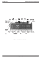
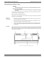
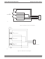
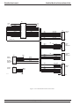
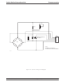
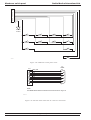
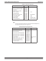
1
Graseby 3200
In-line Pressure
Syringe Pump
INFUSION RATE=
200.0 ml/h
Technical Ser vice
Manual
0473
Part Number 00SM-0130-5
August 2004
© 2004 Smiths Medical International Ltd
Copyright and address
Smiths Medical International Ltd.
Published by Smiths Medical International Limited.
All possible care has been taken in the preparation of this publication, but Smiths Medical International
Limited accepts no liability for any inaccuracies that may be found.
Smiths Medical reserves the right to make changes without notice both to this publication and to
the product which it describes.
© Smiths Medical International Limited 2004
No part of this publication may be reproduced, transmitted, transcribed, or stored in a retrieval
system or translated into any human or computer language in any form by any means without the
prior permission of Smiths Medical International Limited.
SMITHS MEDICAL INTERNATIONAL LIMITED,
COLONIAL WAY,
WATFORD,
HERTFORDSHIRE,
UNITED KINGDOM,
WD24 4LG
TEL: (+44) (0)1923 246434
FAX: (+44) (0)1923 231595
http/www.smiths-medical.com
Registered in England. Company number 362847.
Trademarks and acknowledgements:
Graseby and Smiths are registered trademarks of Smiths Group plc.
All other trademarks are acknowledged as the property of their respective owners.
3200 Service Manual
Issue 5 (August 2004)
Page i
Smiths Medical International Ltd.
Issue record
ISSUE RECORD
Reason for change
Pages
effected
Date
Initial issues
All
Approx. 96
3
Reissue
All
Dec 99
4
Reissue
All
July 00
4 .1
Amendment to 2 pages
ii and 5-9
August 00
4.2
Amendment to 2 pages
ii, 7-15
Feb. 01
Reissue
All
August 04
Issue No.
1 to 2
5
Page ii
Issue 5 (August 2004)
3200 Service Manual
Smiths Medical International Ltd.
Contents
LIST OF CONTENTS
Page
Copyright and address ...................................................................................... i
Warnings and cautions ..................................................................................... x
Abbreviations used ......................................................................................... xiii
CHAPTER 1
INTRODUCTION, FEATURES AND SPECIFICATION
Introduction ................................................................................................... 1-1
Security cover ....................................................................................... 1-1
Features
.................................................................................................... 1-3
Micro-controller ............................................................................................. 1-3
Specification .................................................................................................. 1-4
AC power supply ................................................................................... 1-4
Battery type ........................................................................................... 1-4
Battery life ............................................................................................. 1-4
DC input operation ................................................................................. 1-4
Syringe brands and sizes ...................................................................... 1-4
Infusion rates and increments ................................................................ 1-4
Mass unit programming range ................................................................ 1-4
Volume infused counter ......................................................................... 1-4
In-line occlusion pressure range ............................................................ 1-5
Internally adjustable occlusion pressure ................................................ 1-5
Factory set occlusion ............................................................................ 1-5
Display languages available ................................................................... 1-5
Dimensions ........................................................................................... 1-5
Weight ................................................................................................... 1-5
Temperature range ................................................................................. 1-5
Drive accuracy ...................................................................................... 1-5
History ................................................................................................... 1-5
Electrical safety .................................................................................... 1-5
Design standards ................................................................................... 1-5
UK patent number .................................................................................. 1-5
Printer protocol ...................................................................................... 1-5
Brief history of the Smiths Medical bedside syringe pumps ...................... 1-6
CHAPTER 2
CONFIGURATION, DIAGNOSTICS and OCCLUSION THRUST
Configuration mode ....................................................................................... 2-1
Introduction ............................................................................................ 2-1
Entry into the Configuration mode ............................................................... 2-2
Changing a setting ................................................................................. 2-2
Moving to the next parameter ................................................................ 2-2
Available Configuration mode parameters and settings ............................. 2-3
Syringe brands ....................................................................................... 2-3
Syringe size ........................................................................................... 2-3
Lock progam values ............................................................................... 2-3
3200 Service Manual
Issue 5 (August 2004)
Page iii
Contents
Smiths Medical International Ltd.
CHAPTER 2
(contd.)
Page
Max infusion rate ................................................................................... 2-3
Select pump modes ............................................................................... 2-4
Preset volume mode with time ............................................................... 2-4
KVO rate ................................................................................................ 2-4
Allow mass units option ......................................................................... 2-4
Infusion units ......................................................................................... 2-4
Show rate in ml/h while infusing ............................................................. 2-4
Use pressure transducer ........................................................................ 2-5
Display pressure bar graph .................................................................... 2-5
Allow bolus while running ....................................................................... 2-5
Allow rate change while running ............................................................. 2-5
Intermittent mode start delay ................................................................. 2-5
RS232 Baud rate ................................................................................... 2-5
Communication mode ............................................................................ 2-6
Pump ID ................................................................................................ 2-6
Set key beep volume ............................................................................. 2-6
Pressure units ....................................................................................... 2-6
End of menu .......................................................................................... 2-6
Diagnostic mode ............................................................................................ 2-7
Introduction ........................................................................................... 2-7
Entry into the Diagnostic mode .............................................................. 2-7
Moving to the next display ..................................................................... 2-7
Diagnostic displays ........................................................................................ 2-8
Software ................................................................................................ 2-8
Calibrate transducer ............................................................................... 2-8
Transducer alarm ................................................................................... 2-9
Battery voltage ...................................................................................... 2-9
Language ............................................................................................... 2-9
Number of faults .................................................................................... 2-9
Volume infused ...................................................................................... 2-9
Hours of use .......................................................................................... 2-9
Setting the clock .......................................................................................... 2-10
Entering the clock display ................................................................... 2-10
Disassembly and assembly of casing .........................................................
Taking the casing apart .......................................................................
Assembly ............................................................................................
Occlusion measurements ............................................................................
Thrust measurements ..........................................................................
Syringe stiction ....................................................................................
Thrust checks .....................................................................................
Thrust adjustments ..............................................................................
2-11
2-11
2-11
2-12
2-12
2-12
2-13
2-14
(contd.)
Page iv
Issue 5 (August 2004)
3200 Service Manual
Smiths Medical International Ltd.
Contents
CHAPTER 3
FUNCTIONAL DESCRIPTIONS
Introduction ................................................................................................... 3-1
Drive system .................................................................................................. 3-1
Introduction ........................................................................................... 3-1
Stepper motor and leadscrew ................................................................ 3-1
Microcomputer ....................................................................................... 3-1
Toggle mechanism ................................................................................. 3-1
Plunger clamp ....................................................................................... 3-2
Internal occlusion system ............................................................................. 3-2
In-line occlusion system ............................................................................... 3-2
Electro/mech control system ........................................................................ 3-3
Sensing (alarm) systems ............................................................................... 3-3
Introduction ........................................................................................... 3-3
End of infusion ...................................................................................... 3-3
Syringe nearly empty ............................................................................. 3-3
AC power failure .................................................................................... 3-3
Battery voltage low ................................................................................ 3-4
Self tests/pump malfunction .................................................................. 3-4
Drive disengaged or syringe not fitted .................................................... 3-4
Syringe sizing system ........................................................................... 3-4
Rate setting ........................................................................................... 3-4
Cannot zero extension set ..................................................................... 3-5
Cannot calibrate extension set .............................................................. 3-5
Communications (RS232) failure ............................................................ 3-5
Software
.................................................................................................... 3-5
Self tests ............................................................................................... 3-5
Design ................................................................................................... 3-5
CHAPTER 4
CIRCUIT DESCRIPTIONS
Introduction ................................................................................................... 4-1
Main board ................................................................................................... 4-1
Processor core ...................................................................................... 4-1
Motor interface ...................................................................................... 4-3
Power control ......................................................................................... 4-3
Sensors interface .................................................................................. 4-4
RS232 serial interface ........................................................................... 4-5
Umbilical connector ............................................................................... 4-5
Input/output serial interface ................................................................... 4-5
(contd.)
3200 Service Manual
Issue 5 (August 2004)
Page v
Contents
Smiths Medical International Ltd.
CHAPTER 4 (contd.)
Page
Status sensors ................................................................................................ 4-6
PL 11 output .......................................................................................... 4-7
PL 12 output .......................................................................................... 4-7
Setting RV1 ........................................................................................... 4-8
Syringe size sensors ..................................................................................... 4-9
Status sensors ................................................................................................ 4-9
Distribution board .......................................................................................... 4-9
Pressure sensing board ................................................................................. 4-9
Main board components ................................................................................ 4-9
Regulator board components ........................................................................ 4-9
Membrane switch panel ................................................................................. 4-9
‘D’ connector .................................................................................................. 4-9
CHAPTER 5
FAULT CODES, CLEANING, RENEWAL of FUSES AND REPAIRS
Fault codes .................................................................................................... 5-1
Cleaning
.................................................................................................... 5-4
Repairs
.................................................................................................... 5-4
Renewal of fuses ................................................................................... 5-4
Access to fuses .................................................................................... 5-4
Main board renewal ................................................................................ 5-5
Regulator board renewal ........................................................................ 5-5
Status sensors board renewal ................................................................ 5-5
Plunger clamp and super nut assembly renewal .................................... 5-6
Pole clamp assembly renewal ................................................................ 5-6
Leadscrew assembly renewal ................................................................ 5-6
Motor and gearbox assembly renewal .................................................... 5-7
Occlusion clutch and disc assembly renewal ......................................... 5-7
Membrane switch panel renewal ............................................................ 5-8
Super nut renewal .................................................................................. 5-8
Syringe size sensors assembly renewal ................................................ 5-9
Plunger clamp repair .............................................................................. 5-9
ACAM pressure sensing assembly renewal ........................................... 5-9
Batteries. Checks and replacement ............................................................ 5-10
Checks ................................................................................................ 5-10
Replacement ....................................................................................... 5-10
Front and/or rear case repairs .................................................................... 5-10
(contd.)
Page vi
Issue 5 (August 2004)
3200 Service Manual
Contents
Smiths Medical International Ltd.
CHAPTER 6
Page
FUNCTIONAL TESTS and MANUFACTURING SETTINGS
Functional tests ............................................................................................. 6-1
Plunger clamp alarm checks ........................................................................ 6-4
Ramp check procedures ........................................................................ 6-4
Linear accuracy .............................................................................................. 6-5
Test procedures ..................................................................................... 6-5
Plunger clamp alignment .............................................................................. 6-5
Test procedures ..................................................................................... 6-5
Manufacturing settings .................................................................................. 6-6
CHAPTER 7
ILLUSTRATED PARTS LISTS
General assembly .......................................................................................... 7-1
Plunger clamp and half nut assembly ......................................................... 7-7
Pole clamp assembly: non-rotating .............................................................. 7-8
Pole clamp assembly: Rotating .................................................................... 7-9
Leadscrew assembly ................................................................................... 7-10
Main board assembly .................................................................................. 7-11
Regulator board assembly - AC Power ....................................................... 7-13
CHAPTER 8
BRAUN PERFUSOR CONVERSION
Syringe conversion procedures ................................................................... 8-1
Introduction .......................................................................................... 8-1
Nearly empty flag conversion ............................................................... 8-1
Spacer tube fitment ............................................................................. 8-1
Plunger clamp fitment plate ................................................................. 8-1
Braun Perfusor selection ...................................................................... 8-1
‘P’ label fitment .................................................................................... 8-1
Reselecting ‘various’ syringe brands ........................................................... 8-2
Mechanical procedures ........................................................................ 8-2
Programming procedures ..................................................................... 8-2
(contd.)
3200 Service Manual
Issue 5 (August 2004)
Page vii
Contents
Smiths Medical International Ltd.
CHAPTER 9
Page
DC INPUT VERSION of 3200
Introduction ........................................................................................................... 9-1
DC electrical input supply ..................................................................................... 9-1
APPENDIX
FITTING a MODIFIED SIZE SENSOR FLAG
Introduction .................................................................................................. A-1
Opening the case .......................................................................................... A-2
Removal of old SSF ...................................................................................... A-2
Reassembly ................................................................................................... A-3
Final testing .................................................................................................. A-3
Setting the Size Sensor Flag ....................................................................... A-4
LIST OF TABLES
Table
Page
4.1
RS232 D connector ......................................................................................... 4-5
4.2
PL11 connections ........................................................................................... 4-7
4.3
Temperature/voltage range for setting RV ........................................................ 4-8
5.1
5.2
5.3
5.4
5.5
Main processor fault codes ............................................................................. 5-1
Fault causes and actions ................................................................................ 5-3
Front case spares kit ....................................................................................... 5-11
Size Sensor Flag spares kit ............................................................................ 5-11
Rear case spares kit ....................................................................................... 5-12
6.1
6.2
Functional tests .............................................................................................. 6-1
Manufacturing settings .................................................................................... 6-6
A.1
3200 Syringe Size Sensor Gauges (white) ...................................................... A-5
LIST OF FIGURES
Figure
Page
1.1 Itemised front view of the pump ...................................................................... 1-2
2.1 Case fixing screw tightening order ................................................................. 2-11
2.2 Thrust measuring set up ................................................................................ 2-13
4.1
4.2
4.3
4.4
4.5
4.6
4.7
4.8
4.9
4.10
4.11
Page viii
Overall block diagram of the 3200 system .....................................................
Main board block diagram ..............................................................................
Processor core circuit diagram ......................................................................
Motor interface circuit diagram .......................................................................
Power control circuit diagram .........................................................................
Sensors and pressure sensing interface ........................................................
Pressure sensing interface circuit diagram ....................................................
RS232 interface circuit diagram .....................................................................
Umbilical cable connections ..........................................................................
Input/output serial interface circuit diagram ....................................................
Overview of the regulator ...............................................................................
Issue 5 (August 2004)
4-10
4-11
4-12
4-13
4-14
4-15
4-16
4-17
4-18
4-19
4-20
(contd.)
3200 Service Manual
Smiths Medical International Ltd.
Contents
LIST OF FIGURES (contd.)
Figure
Page
4.12 Regulator live (primary) circuit diagram ..........................................................
4.13 Regulator isolated (secondary) circuit diagram ...............................................
4.14 Syringe size sensors circuit diagram .............................................................
4.15 Status sensors circuit diagram ......................................................................
4.16 Distribution board connections .......................................................................
4.17 Pressure sensing circuit diagram ...................................................................
4.18 Membrane switch panel circuit .......................................................................
4.19 Internal ribbon cable and ‘D’ connector connections .......................................
4-21
4-22
4-23
4-23
4-24
4-25
4-26
4-26
5.1
5.2
Half nut (obsolete)/Super nut ........................................................................... 5-8
Strengthened front and rear case mouldings .................................................. 5-10
6.1
6.2
6.3
6.4
Outline of dual ramp gauge .............................................................................. 6-4
Ramp check - Square/Ramp style flags ........................................................... 6-4
Linear accuracy gauge ..................................................................................... 6-5
Taper gauge .................................................................................................... 6-5
7.1
7.2
7.3a
7.3b
7.4
7.5
7.6
General assembly ............................................................................................ 7-3
Plunger clamp and half nut assembly .............................................................. 7-6
Pole clamp assembly diagram - Non-rotating ................................................... 7-7
Pole clamp assembly diagram - Rotating ......................................................... 7-8
Leadscrew assembly ....................................................................................... 7-9
Main board assembly ..................................................................................... 7-12
Regulator board assembly - AC Power ........................................................... 7-13
8.1
Braun Perfusor conversion: parts required ....................................................... 8-2
9.1
9.2
9.3
Diagram of pump chassis connector ................................................................ 9-1
Power supply circuit diagram ........................................................................... 9-2
Layout of components on the power supply board ........................................... 9-2
A.1
A.2
A.3
New modified Syringe Size Sensor Flag .......................................................... A-1
Order for tightening the case screws ................................................................ A-3
Size Sensor Flag: general details ..................................................................... A-5
3200 Service Manual
Issue 5 (August 2004)
Page ix
Warnings and cautions
Smiths Medical International Ltd.
Introduction
This Technical Service Manual together with the Instruction Manual, contains all the information that is needed in order
to maintain, repair and operate the Graseby 3200 pump. The contents of this Manual are intended to be read and used
by suitably qualified personnel.
AC input power connecting socket/cable
The AC input power socket that connects to the rear of the pump has three connections (live, neutral and earth)
provided by a 3-way power cable. As the casing is doubly insulated, the AC input connector situated on the pump
only utilises two connections (live and neutral), there is no third earth pin. This method of AC input enables similar AC
input sockets (if required) to that supplied by Smiths Medical to be used.
Warnings and cautions
Warnings tell you about dangerous conditions that could lead to death or serious injury to the user or patient that can
occur if you do not obey all of the instructions in this manual.
WARNINGS
1. WARNING: To avoid over- or under- infusion, always verify that the brand and size of the loaded syringe are the
same as the brand and size displayed on the screen before starting an infusion. Failure to do so may result in an
inaccurate delivery of medication, resulting in patient injury or death.
2. WARNING: To avoid incorrect or inappropriate configuration of the pump, the Configuration menu must only be
selected by qualified persons or authorised personnel. Incorrect pump configuration could lead to inappropriate
infusion resulting in patient injury or death.
3. WARNING: This equipment is not suitable for use in the presence of flammable anaesthetics, oxygen-enriched
or explosive atmospheres. The use of the device in such atmospheres may lead to explosion or fire.
4. WARNING: To avoid possible malfunction of the pump, do not expose the pump to X- rays, gamma rays or
ionizing radiation, or to the RF interference or strong electric/magnetic fields emitted (for example) by diathermy
equipment or mobile telephones. If the pump is used in the presence of, or in combination with Magnetic
Resonance Imaging (MRI) machines it must be protected from the magnetic field emitted by such equipment.
Malfunction of the pump can cause incorrect infusion or loss of infusion resulting in patient injury or death.
5. WARNING: Operation of the pump outside the temperature limits defined in the specification may result in
erroneous operation. Ensure that the temperature is within the specified limits. Failure to do so may result in
patient injury or user injury.
6. WARNING: In order to ensure that the intended infusion is performed, data must be entered correctly. Likewise
before confirming any displayed data the user should ensure that it is correct. Failure to do so may result in
compromised function of the product, patient injury or user injury.
7. WARNING: Failure to respond promptly to an alarm may result in patient injury or death.
8. WARNING: Failure to follow the Service Manual’s maintenance schedule recommendations may result in
compromised function of the product and lead to patient injury or death.
9. WARNING: It is essential that clinical staff remain within visual and audible range of the pump so that critical
alarms can be seen or heard and responded to.
10. WARNING: The user should ensure that the performance offered by the pump is fit for the intended purpose.
Failure to do so may result in compromised function of the product, patient injury or user injury.
11. WARNING: When the pump is carrying out an infusion, to ensure that electrical safety is maintained only items
of equipment that conform to EN60950 are to be connected to the RS232 connector situated at the base of the
pump, otherwise patient safety may be compromised.
12. WARNING: Correct management of battery charging is essential to ensure that the pump can operate on
batteries for the time specified. Failure to do so may lead to impaired functioning of the pump, resulting in
patient injury or death.
13. WARNING: Do not use a faulty pump. If the pump develops a fault then an alarm will sound; the display will
indicate a FAULT condition and the pump will fail to infuse. Incorrect performance of the pump can cause
complications resulting in patient injury or death.
If the pump develops a fault then it must be referred to a suitably qualified engineer or returned to Graseby
Medical in order to have the fault rectified.
14. WARNING: Failure to use the mains lead clamp means that the pump may be accidentally or erroneously
disconnected from the mains. Although there is battery backup in case this happens, the battery may not be
sufficiently charged. Consequently there is a risk of the pump not functioning, which could lead to patient injury
or death.
15. WARNING: If an occlusion alarm occurs, immediately clamp the line to eliminate the possibility of a bolus being
delivered to the patient. Then inspect the fluid pathway for kinks, clogged catheter, etc. in order to remove the
occlusion prior to restarting the infusion. An unintentional bolus of medication can result in patient injury or
death.
Page x
Issue 5 (August 2004)
3200 Service Manual
Warnings and cautions
Smiths Medical International Ltd.
16. WARNING: Use only the syringes and administration sets listed in the Specification (Chapter 1).
Failure to do so may result in an inaccurate delivery. Smiths Medical does not guarantee performance of the
pump if syringes other than those listed are used. Incorrect function or performance of the pump can cause
complications resulting in patient injury or death.
17. WARNING: The volume of fluid contained in the connecting tubing is a residual amount and will not be infused.
Hence this extra volume of fluid must be allowed for when initially filling the syringe and purging the system.
Under-delivery of medication can cause complications resulting in patient injury or death.
18. WARNING: To avoid patient embolism, ensure that the patient tubing is purged of all air bubbles before
administering any medication. The pump provides a purge facility to assist with this process. The presence of
air within the medication can result in complications leading to patient injury or death.
19. WARNING: To avoid syphoning of the syringe contents (free flow), ensure that the syringe is correctly loaded
into the pump, that the syringe plunger is properly engaged by the pump’s actuator and that the pump is placed
not more than 80cm above the infusion site. Syphoning can result in over-infusion leading to patient injury or
death.
20. WARNING: To avoid over-infusion, do not purge the infusion line when the administration set is connected to the
patient. Over-infusion of medication can result in patient injury or death.
21. WARNING: To avoid the pump becoming detached from an IV pole always make sure that the pump is securely
fixed to the pole. Always check the security and stability of the assembly with the pump mounted.
22. WARNING: Following a significant liquid spill onto the pump, it should be wiped dry and inspected by service
personnel before being returned to service. Failure to do so may result in compromised functioning of the pump,
leading to patient or user injury or death.
23. WARNING: When using a syringe smaller than 50/60 ml the occlusion pressure will increase as the diameter of
the syringe decreases, i.e. the smaller the syringe the higher the pressure.
24. WARNING: For high risk or critical infusions, the use of the dedicated 3200 Extension set incorporating the
pressure sensing disc is recommended in order that occlusion pressure can be appropriately set and
monitored during an infusion.
25. WARNING: The patient history is lost when the clock is reset.
26. WARNING: Only adequately qualified personnel should maintain and repair the pump.
27. WARNING: The pump must be disconnected from the AC power supply before the case is opened.
28. WARNING: The Configuration and Diagnostic mode must only be used by personnel who are adequately qualified and
have previous training in the use of the pump.
29. WARNING: The safety and reliability of the pump may be compromised by the use of parts other than those specified
in this Manual.
30. WARNING: When a new Syringe Size Sensor Flag has been fitted to the pump (see Appendix), then the pump must be
tested using the new syringe size sensor gauges available from Smiths Medical (part number 0131-0202). Page 3 of
the Appendix gives details of the Final Testing procedures.
31. WARNING: The pump must be set to display the brand and the size of syringe that is going to be used. Using a
different brand or size of syringe to that being displayed could lead to the incorrect amount of drug being administered,
that could result in injury or death.
32. WARNING: The internal pump batteries must be disposed of in accordance with the manufacturers instructions.
Lead acid batteries must NOT be placed in the normal waste stream.
3200 Service Manual
Issue 5 (August 2004)
Page xi
Smiths Medical International Ltd.
Warnings and cautions
CAUTIONS
Cautions tell you about dangerous conditions that can occur and cause damage to the pump if you do not obey all
of the instructions in this manual.
1. CAUTION: Refer all service, repair and calibrations only to qualified technical personnel. Unauthorised
modifications to the pump must not be carried out.
2. CAUTION: When turning the pump on if screens similar to those illustrated are not displayed, do not use the
pump. Send the pump to a suitably qualified engineer or return it to Smiths Medical in order to have the fault
rectified.
3. CAUTION: Do not use cleaning and disinfecting agents other than the approved ones specified here.
4. CAUTION: The pump must not be immersed in any liquids or exposed to strong organic solvents. Wipe off spills
immediately, and do not allow fluid or residues to remain on the pump. Additionally, the pump is not designed to
be autoclaved, steam-sterilised, ETO-sterilised or subjected to temperatures in excess of 45° C (113° F). Failure
to observe this caution may cause serious damage to the pump.
5. CAUTION: During the removal and replacement of a pump's components, strict observance to Electro Static
Discharge (ESD) rules must be observed at all times, i.e. an earthing strap must be worn. Failure to apply ESD
protection may result in serious damage to the product and possible malfunction. Ensure that any replacement
printed circuit board or other ESD sensitive items are stored in an anti-static container.
Page xii
Issue 5 (August 2004)
3200 Service Manual
Smiths Medical International Ltd.
Abbreviations
used
The following list shows the abbreviations that have been used at various
places throughout this Manual.
Abbreviation
Full name
AC
A-to-D
C
CMOS
cNm
COP
DC
D
EEPROM
Alternating current
Analogue-to-digital
Capacitor or Centigrade
Complimentary metal oxide silicone
Centinewton metre
Computer operating properly
Direct current
Diode
Electrically erasable and programmable read
only memory
Erasable program
Figure
Hertz (cycles per second)
Integrated circuit
IDentification
Kilo byte
Kilo gram
Keep vein open
Liquid crystal
Light emitting diode
Manually controlled infusion
Mega Hertz
Millilitre per hour
Millilitre
Millimetre
Pounds per square inch
Pulse width modulated
Resistance
Random access memory
Target controlled infusion
Volts
Vacuum fluorescent
Watts
EPROM
Fig
Hz
IC
ID
kbyte
kg
KVO
LC
LED
MCI
MHz
ml/h
ml
mm
PSI
PWM
R
RAM
TCI
V
VF
W
3200 Service Manual
Issue 5 (August 2004)
Page xiii
CHAPTER 1
INTRODUCTION, FEATURES and SPECIFICATION
3200
In-line Pressure Syringe Pump
Smiths Medical International Ltd.
Introduction
CHAPTER 1
INTRODUCTION, FEATURES and SPECIFICATION
Introduction
The 3200 is a microcomputer controlled syringe pump that has primarily been developed for
the neonatal infusion of sterile liquids.
The pump has an In-line (wet-side) pressure sensing system for accurate occlusion detection.
The pump is capable of operating in any one of three different infusion modes, as follows:
•
continuous,
•
preset, or
•
intermittent.
And is able to carry out an infusion using a 5, 10, 20, 30, 50/60 ml size syringe.
The pump incorporates a dot matrix vacuum fluorescent display that provides a constant
indication of the pump’s operation. A choice of any one of the following languages is available (with the appropriate software) via the diagnostic options mode:
English, Dutch, French, German, Italian, Norwegian and Spanish.
The pump can be Configured by the user to work with one of a range of brands of syringe.
It automatically senses the size of the syringe fitted to the pump. The rate of the pump can
be set to operate with either mass units or ml/hour.
The pump is able to dispense liquids at rates of between 0.05 and 200 ml/hour.
The pump keeps the running total of the volume infused, and a history of events as they
occur. About 1,500 events can be logged, complete with the date and time of each.
This compact and robust pump can be used on either a table top or mounted via its pole
clamp to an IV (Intravenous) pole. The pump’s history can either be viewed on the screen or
output to a printer.
An RS232 interface link connects the pump to either a printer or a computer. This allows the
pump’s history to be printed or externally monitored.
Safety features are built into the pump and its software. This includes a set of self test
routines which are run when the pump is switched on.
Users are warned of such incidents as occlusion or power failure by both visible and audible
alarms.
The pump can be powered from either an AC supply or internal rechargeable batteries.
The batteries can power the pump for at least two and a half hours from a fully charged
condition.
A DC version of the 3200 also exists, that requires an input supply of 10 V to 28 V DC (see
Chapter 9).
This Manual refers to pumps that have software Version 2.20 installed. Software versions
other than 2.30 may show slight deviations from certain features described in this Manual.
Security cover
3200 Service Manual
An optional security cover kit is available (part number 0131-0277). The kit includes all the
items required to modify the pump, including comprehensive fitting instructions. When fitted,
the kit protects the syringe from tampering only; it provides no other security. It does not
lockout the keypad or give audible or visual alarms when opened.
Issue 5 (August 2004)
1—1
Introduction
Smiths Medical International Ltd.
Figure 1.1 Itemised front view of the pump
1—2
Issue 5 (August 2004)
3200 Service Manual
Smiths Medical International Ltd.
Features
Microcontroller
Features
The key features of the 3200 are as follows:
•
In-line (wet-side) pressure sensing,
•
automatic syringe size sensing,
•
up to 1500 History events storage,
•
universal AC supply powered or battery powered,
•
can be Configured to work with a range of syringe brands,
•
advanced safety features,
•
state-of-the-art electronics,
•
clear text display,
•
comprehensive range of alarms,
•
RS232 interface,
•
simple to use and service,
•
all materials used in this product are latex free.
The pump makes use of a sophisticated micro-controller which combines microprocessor
facilities with the following:
•
0n-board non-volatile memory,
•
RAM,
•
ROM,
•
an analogue-to-digital converter,
•
communications circuitry,
•
four 8-bit pulse-width modulated outputs,
•
an internal watchdog (COP).
These facilities are usually provided by many separate silicon chips, the use of a single
micro-controller greatly increases the pump’s reliability.
3200 Service Manual
Issue 5 (August 2004)
1—3
Specification
Smiths Medical International Ltd.
Specification
AC power
supply:
100 V to 240 V at 50/60 Hertz, 40 VA.
The power supply uses primary switching in order to utilise the AC supplies of most
countries.
Battery type:
Sealed lead acid, rechargeable (Cyclon, 3 off). Smiths Medical recommend that the
batteries are checked at least annually (see page 5-10).
Battery life:
More than 2.5 hours of normal pump operation when the batteries are fully charged.
With the AC supply connected, up to 14 hours are required to fully recharge low voltage
batteries.
DC input
operation:
Syringe brands
and sizes:
3200 DC variant pump.
10 V to 28 V DC at a maximum of 4 amps input supply (see Chapter 9).
BD Plastipak...
5, 10, 20, 30/50 and 50/60 ml.
Injectomat...
10 ml and 50 ml.
IMS Pumpjet...
30 ml, prefilled.
Monoject...
5, 10, 20, 30/35 and 50/60 ml.
Braun Omnifix...
5, 10, 20, 30 and 50/60 ml.
Terumo...
5, 10, 20, 30/35 and 50/60 ml.
BD Plastipak (A)... 5, 10, 20, 30/35 and 50/60 ml.
The BD Plastipak (A) syringe accommodates the American manufactured 10 ml syringe,
which differs slightly in length to the European version. All other syringe sizes in the BD
Plastipak selection are identical to the standard BD Plastipak syringes.
Infusion rates
and increments:
Braun Perfusor...
Optional (see Chapter 8).
Rates
0.05 to 1.0 ml/h...
1 to 200 ml/h...
Increments
0.01 ml/h
0.1 ml/h
0.01 to 999 mg/kg/h
0.01 to 999 mg/kg/min
0.01 to 999 µg/kg/h
0.01 to 999 µg/kg/min
0.01 to 999 mg/h
0.01 to 999 µg/h.
Mass unit
programming
range:
Patient weight...
Drug mass...
Drug volume...
Volume infused
counter:
0 to 999.9 ml in 0.1 ml increments.
1—4
0.4 to 200 kg.
1 µg to 999 mg.
1 ml to 60 ml.
Issue 5 (August 2004)
3200 Service Manual
Smiths Medical International Ltd.
Specification
Specification
(contd.)
In-line occlusion
pressure range:
Using a 30 ml sized syringe:
0 to 7.42 kg (1000 mmHg).
0 to 1355 cmH2O.
0 to 133.3 kPa.
0 to 1316 mBar.
0 to 19.34 psi.
Using a 50 ml syringe, 0 to 4.83 kg (0 to 650 mmHg).
Internally adjustable
occlusion pressure:
Using a 50 ml syringe, 1.85 kg (250 mmHg) to 4.83 kg (650 mmHg).
Factory set occlusion:
3.5 kg (471 mmHg) to 4.2 kg (565 mmHg).
Display languages
available:
Dutch.
English.
French.
German.
Italian.
Norwegian.
Spanish.
Dimensions:
350 x 195 x 115 mm, with pole clamp fitted and plunger clamp closed.
Weight:
Not exceeding 3.5 kg including the batteries and pole clamp.
Temperature
range:
Operating conditions:
+5°C to +40°C, 30 to 75% Rh, 700 to 1060 hPa.
Storage conditions:
-40°C to +70°C, 30 to 90% Rh, 700 to 1060 hPa.
Drive accuracy:
±2%.
History:
1500 events can be stored.
Electrical safety:
Class II
Type CF
Drip proof IPX1.
Design standards:
BS5724 Part 1
IEC601 Part 1
VFG1046/1984.
UK patent number:
2229497.
Printer protocol:
Serial, 8 bits, no parity, 1 stop bit.
3200 Service Manual
Issue 5 (August 2004)
1—5
Development of 3000 series
Smiths Medical International Ltd.
Brief history of Graseby bedside syringe pumps
MS2000
The first Graseby bedside syringe pump was the MS2000. This was a basic syringe pump capable of infusions within
the range of 0.1 ml/hr to 99.9 ml/hr. It had a totaliser, a limited infusion capability, a built-in pole clamp and was
designed for vertical operation. The MS2000 was powered by an AC supply or its internal DC batteries. This pump is
no longer manufactured.
PCAS
The PCAS pump was developed from the MS2000 to satisfy the growing interest in Patient Controlled Analgesia
(PCA). The PCAS was very similar to the MS2000 in both appearance and mechanical design, but used a different
microprocessor with the capability of running the extra features required for PCA. It was eventually replaced by the
3300 pump. A printer port was also incorporated. This pump is no longer manufactured.
3000
The first pump in the 3000 Series of syringe pumps was the 3000. This pump was a low-cost alternative to the
MS2000 and satisfied the need for a horizontally mounted pump. The 3000 did not have an internal battery supply.
This pump is no longer manufactured.
3100
The 3100 syringe pump was developed from the 3000. It is very similar mechanically but with improved electronics.
Dual processors were incorporated, with a vacuum fluorescent text display and internal batteries. The maximum
infusion rate was increased to 199.9 ml/hr and different syringe sizes were able to be used (automatically sensed).
Extra software features, such as the intelligent ‘near end’ alarm, were also incorporated.
3300
The next bedside syringe pump to be developed was the 3300. This was similar in mechanical and electronic design
to the 3100 but the features were specifically for the now more mature PCA market. A lockable syringe cover was
added for security against drug theft; a four line LC display was added and internal history recording (1500 events)
with printout was also added. With the growth in PCA knowledge in the medical community, many more software
features were incorporated into the 3300 to aid PCA administration.
3400
The 3400 was developed (again from the 3100) to satisfy the need for a high speed infusion pump for intravenous
anaesthesia. Advances in micro-controller technology allowed the use of a single device to control all the pumps
features. The maximum infusion rate was raised to 1200.0 ml/hr and bolusing facilities were also added. An infusion
rate calculation facility was later added to the software.
A larger liquid crystal display was used on the 3400 with the ability to display text in different sizes, also ‘soft-keys’
were used to make the user interface simpler. The range of syringe sizes that could be used was also increased.
For more advanced applications the pump could be controlled by a computer.
3200
The 3200 was developed as a general purpose syringe pump. Wet-side pressure sensing, intermittent infusion
capabilities, and computer interfacing were added. The wet-side occlusion pressure monitoring made the pump
particularly suitable for use in intensive-care baby units. A large text vacuum fluorescent display was added, and the
increased syringe size range of the 3400 remained.
A DC input supply (10 V to 28 V DC) version of the 3200 is also manufactured by Smiths Medical. This variant is
primarily intended for use in an aviation environment, but may be utilised in an environment where the required DC
voltage exists.
3500
There are two versions of the 3500, as follows:
1. A Manually Controlled Infusion (MCI) only pump.
2. An MCI plus a Target Controlled Infusion (TCI) pump.
The 3500 was developed from the 3400 and retains all the 3400 facilities.
The ‘MCI plus TCI’ pump carries out a TCI using the Diprivan drug. This version of the 3500 incorporates a Diprifusor
module manufactured by Zeneca Pharmaceuticals. A new main circuit board and new software allows the 3500 to
interface with the Diprifusor module. A 3500 non-TCI pump can be converted to become a 3500 plus TCI pump.
3150
The 3150 is very similar to the 3200 general purpose pump. The main difference being that the In-line (wet-side) pressure
sensing system in not available on the 3150, i.e. the pressure transducer is not fitted.
1—6
Issue 5 (August 2004)
3200 Service Manual
CHAPTER 2
CONFIGURATION, DIAGNOSTICS
and OCCLUSION THRUST
3200
In-line Pressure Syringe Pump
Configuration mode
Smiths Medical International Ltd.
CHAPTER 2
CONFIGURATION, DIAGNOSTICS and OCCLUSION THRUST
Configuration mode
WARNING
The Configuration mode must only be used by personnel who are
adequately qualified and have had previous training in the use of the 3200.
Introduction
The Configuration mode allows the various different pump parameters to be displayed, which
in turn allows various settings within these parameters to be set to the values required for the
infusion.
The full list of Configuration parameters is shown below, but the availability of some parameters
depends upon the setting of other parameters. Each parameter is further detailed in the
sections that follow this list:
3200 Service Manual
1.
Syringe brand.
2.
Syringe size.
3.
Lock program values.
4.
Max infusion rate.
5.
Select pump modes.
6.
Preset volume mode with time.
7.
KVO rate.
8.
Allow mass unit.
9.
Infusion units, mg/kg/h.
10.
Infusion units, µg/kg/h.
11.
Infusion units, mg/kg/min.
12.
Infusion units, µg/kg/min.
13.
Infusion units, mg/h.
14.
Infusion units, µg/h.
15.
Show rate in ml/h while infusing.
16.
Use pressure transducer.
17.
Display pressure bar graph.
18.
Allow bolus while running.
19.
Allow rate change while running.
20.
Intermittent mode start delay.
21.
RS232 Baud rate.
22.
Communication mode.
23.
Pump ID.
24.
Set key beep volume.
25.
Pressure units.
26.
End of menu.
Issue 5 (August 2004)
2—1
Configuration mode
Smiths Medical International Ltd.
Entry into the Configuration mode
With the pump switched on and in the set-up mode, complete the following procedures to
enter the Configuration mode.
Press and hold down the PURGE button. Press either the ▲ or ▼ button. The following is
displayed:
CONFIGURATION MODE ?
(USE WITH CARE)
Within six seconds of pressing the buttons, press the START button to confirm the
configuration mode.
Note:
If the START button is not pressed within six seconds, the pump returns to
its set-up mode.
A display similar to the following will be shown:
SYRINGE TYPE=
BD PLASTIPAK
Changing a
setting
Press the ▲ or ▼ button sequentially to scroll through the settings available within each
parameter. The setting required must be displayed.
The various settings are retained by the pump until the Configuration mode is re-entered
and the setting reset.
Moving to the next
parameter
Press the ENTER button to move to the next parameter. If a new choice is required,
repeat the above. Sequentially pressing the ENTER button scrolls through the available
Configuration parameters.
To exit the Configuration mode and return to the set-up mode press the STOP button at
any time.
2—2
Issue 5 (August 2004)
3200 Service Manual
Smiths Medical International Ltd.
Configuration mode
Available Configuration mode parameters and settings
Syringe brands 1.
WARNING
The pump must be set to operate with the brand and size of syringe that
is going to be used. Using a different brand to that selected could lead
to the incorrect amount of drug being administered, resulting in injury or
death.
The syringe parameter allows a choice of any one of eight different syringe brands to
be pre-selected and used during an infusion.
Choice:
Syringe size
2.
BD PLASTIPAK
INJECTOMAT
IMS PUMPJET 30
MONOJECT
BRAUN OMNIFIX
TERUMO
BD PLASTIPAK (A), see page 1-4.
BRAUN PERFUSOR, optional syringe. See Chapter 8.
This parameter allows the five syringe sizes that are available to be locked to any one
size, thus excluding the other four settings, or NOT LOCKED in order to accept all five choices.
Choice:
Lock program
values
3.
5 ml ONLY
10 ml ONLY
20 ml ONLY
30 ml ONLY
50/60 ml ONLY
NOT LOCKED
After the required infusion program values have been set into the pump (i.e. during the
set-up mode) this parameter allows these set-up program infusion values to be temporarily locked in. This prevents tampering and is useful for home treatment.
The lock must be turned off (i.e. the lock program value set to NO) to change the set-up
infusion mode.
Choice:
Max infusion
rate
4.
YES or NO
This parameter allows the maximum infusion rate to be set. Above the set rate, an
alarm message is displayed; the pump will not infuse.
The infusion rate that is initially entered into the pump in the set-up mode acts
independently of the maximum infusion rate that can be entered in the configuration
mode.
The configuration mode maximum rate setting takes priority with respect to the
maximum infusion rate that can be used.
The Instruction Manual details the maximum infusion rates for the five different syringe
sizes that are available.
Choice:
10 to 200.0 ml/h in 0.1 ml steps.
(contd.)
3200 Service Manual
Issue 5 (August 2004)
2—3
Configuration mode
Select pump
modes
5.
Smiths Medical International Ltd.
This parameter shows the versatility of the 3200 by allowing five different combinations of the three modes of infusions to be pre-selected.
Choice:
Preset volume
mode with
time
6.
This parameter allows either a preset volume with time (YES selected) or a preset
volume with rate (NO selected).
Choice:
KVO rate
7.
8.
YES or NO.
This parameter allows either a KVO rate of 0.50 ml/h or 0.05 ml/h to be chosen.
Choice:
Allow mass
units option
ALL MODES AVAILABLE
CONTINUOUS & PRESET
INTERMITTENT ONLY
PRESET VOLUME ONLY
CONTINUOUS ONLY
0.5 ml/h or 0.05 ml/h.
When YES is chosen this parameter allows any one of the six mass units to be
selected [see parameters (9) to (14)].
When NO is chosen this parameter allows only ml/h to be selected.
Choice:
Infusion units
When YES is chosen from parameter (8), parameters (9) to (14) allow any combination
of mass units from the following list:
9.
mg/kg/h.
10.
µg/kg/h.
11.
mg/kg/min.
12.
µg/kg/min.
13.
mg/h.
14.
µg/h.
Choice:
Show rate in
ml/h while
infusing
YES or NO
15.
YES or NO for each parameter.
This parameter allows the infusion rate, when set to mass units, i.e. YES, to also be
displayed in ml/h when infusing.
Choice:
YES/NO
(contd.)
2—4
Issue 5 (August 2004)
3200 Service Manual
Smiths Medical International Ltd.
Configuration mode
Use pressure 16. This parameter allows a selection of in-line pressure sensing options.
transducer
If YES is chosen, the pump senses the presence of a syringe extension set and shows
the in-line pressure on the display.
If the extension set is not being used, choosing YES causes the following prompt to
appear when the START button is pressed...
Press START to run without disposable
This display serves as a warning that the extension set is not being used. Pressing the
START button a second time runs the pump without the extension set.
Choosing NO also allows the pump to run without the extension set.
Choice:
Display
pressure
bar graph
17.
YES or NO
This parameter allows the pressure bar graph to be displayed when YES is chosen.
If NO is chosen, the display will be similar to the following:
10 mmHg (75)
Choice:
Allow bolus 18.
while running
If YES is chosen this parameter allows the PURGE button to infuse a bolus when the
pump is running.
Choice:
Allow rate
19.
change while
running
YES or NO
YES or NO
If YES is chosen, this parameter allows the infusion rate to be changed during the actual
infusion.
The infusion can thus be titrated to the physiological response of the patient.
Choice:
Intermittent
mode start
delay
20.
In the Intermittent mode, this parameter allows a start delay between 0 and 24 hours to
be chosen before the intermittent regime is started.
Choice:
RS232 Baud
rate
21.
YES or NO
YES or NO
This parameter allows a choice of Baud rates when the pump is connected to a PC or a
printer.
Choice:
9600
4800
2400
1200
600
300
(contd.)
3200 Service Manual
Issue 5 (August 2004)
2—5
Configuration mode
Communication mode
Smiths Medical International Ltd.
22. This parameter allows a computer to interrogate both the information stored in the pump
and the pumps status.
Choice:
MONITOR
ONLY..
this choice allows an external computer or a printer to
be connected to the pump.
NONE...
this choice ensures that a computer cannot be used to
monitor the pump.
Contact Smiths Medical (Customer Support) for information on setting up a computer
link.
Pump ID
23.
The identification (ID) of the pump appears on the initial power up display. It also
appears on the printout.
This parameter allows an ID of up to 12 alphanumeric characters to be chosen.
To change the pump’s ID use the START, ▲ or ▼ and ENTER buttons, and press STOP
when finished.
A typical ID display is shown below:
GRASEBY-3200
The pump ID accepts 12 characters exactly. A blank space is not provided.
Set key
beep
volume
24.
This parameter allows the sound of the key beep to be adjusted so that it is at an
appropriate level for the existing environment.
Choice:
1 to 10.
1 is quiet.
10 is loud.
As the choice is altered from 1 to 10, the sound level increases.
Pressure units 25.
This parameter allows any one of five choices to be made for the in-line pressure
sensor display, as shown below:
Choice:
End of menu
2—6
26.
mmHg.
mbar.
cmH2O.
psi.
kPa.
Press the STOP button to exit from the configuration mode.
Issue 5 (August 2004)
3200 Service Manual
Smiths Medical International Ltd.
Diagnostic
mode
Introduction
Diagnostic mode
WARNING
The Diagnostic mode must only be used by personnel who are adequately
qualified and have been trained in the use of the 3200.
The Diagnostic mode has seven available options which can be used to view, select and
complete the procedures detailed in the following sections.
The Diagnostic options are:
•
•
•
•
•
•
•
Software version.
Calibrate transducer.
Battery voltage.
Language.
Number of faults.
Total volume infused.
Total hours of use.
Entry into the
To enter the Diagnostic mode, complete the following procedures with the pump switched
Diagnostic mode on:
Press and hold down the ALARM button and press either the ▲ or ▼ button. The following is displayed:
DIAGNOSTIC MODE ?
(USE WITH CARE)
Within six seconds of pressing the buttons, press the START button to confirm the Diagnostic mode is required:
Note:
If the START button is not pressed within six seconds of the display
appearing, the pump will return to its set-up mode.
A display similar to the one shown below appears:
SOFTWARE VERSION=
2.30
Moving to the
next display
Press the ENTER button to move to the next display. Sequentially pressing the ENTER
button scrolls through the available Diagnostic displays.
Press the STOP button at any time in order to exit the Diagnostic mode and return to the
set-up mode.
3200 Service Manual
Issue 5 (August 2004)
2—7
Diagnostic mode
Smiths Medical International Ltd.
Diagnostic displays
Software
1.
The software display shows the version of software installed in the pump. It is similar to
the following display:
SOFTWARE VERSION=
2.30
Calibrate
transducer
2.
To calibrate the transducer, both a syringe extension set and a mercurial sphygmomanometer
(or a similar pressure reading device) are used.
Insert the pressure sensing disc into the pump’s sensor housing and attach the disc to the
pressure reading device.
In the Diagnostic mode, scroll through the displays until the following display appears:
PRESS START TO
CALIBRATE TRANSDUCER
Press the START button and the following display is shown:
SET ZERO mmHg
AND PRESS START
Set the pressure reading device to zero mmHg and then press the START button.
The following two displays automatically appears:
ZEROING
PLEASE WAIT
SET 300 mmHg
AND PRESS START
Set the pressure reading device to 300 mmHg and press the START button.
The following three displays automatically appear:
CALIBRATING
PLEASE WAIT
CALIBRATION
COMPLETE
PRESS START TO
CALIBRATE TRANSDUCER
2—8
Issue 5 (August 2004)
3200 Service Manual
Smiths Medical International Ltd.
Diagnostic mode
After carrying out the previous display request (i.e. pressing START), press STOP to return
the pump to its set-up mode.
Transducer
alarm
If a fault occurs within the transducer set-up system, a pulsing loud alarm (silenceable)
occurs and the following alarm display appears:
WARNING: CANNOT
CALIBRATE TRANSDUCER
Battery
voltage
3.
The battery voltage display is similar to the following:
BATTERY VOLTAGE=
6.9 V
Language
4.
Various languages may be selected and used for display purposes. The English display
selection is shown below:
LANGUAGE=
ENGLISH
The other language displays are:
•
•
•
•
•
Number of
faults
5.
SPRÅK
= SVENSKA
TAAL
= NEDERLANDS.
LINGUA = ITALIANO.
SPRACHE = DEUTSCH.
LANGUE = FRANCAIS.
The total number of faults that may have occurred to the pump since manufacture is
displayed when in this parameter:
NUMBER OF FAULTS=
1
Volume
infused
6.
The total volume of liquid that has been infused since the pump was manufactured is
displayed when in this parameter:
TOTAL VOLUME INFUSED
0.06 litre
Hours of use 7.
The total number of hours that the pump has been switched on is displayed when in this
parameter is selected:
TOTAL HOURS OF USE=
9.0 hours
3200 Service Manual
Issue 5 (August 2004)
2—9
Setting the clock
Smiths Medical International Ltd.
Setting the clock
The time and date may be viewed; if required, both may be reset. The procedures for
entering and setting the clock are detailed below.
Entering the
clock display
Simultaneously press the...
ALARM, ENTER and DISPLAY button,
and a display similar to the one shown below appears:
SET CLOCK ?
15:19:22
31-AUG-2003
Within six seconds of pressing the buttons, press the START button to amend the time
and/or date.
Note:
If the START button is not pressed within six seconds of the display appearing
the pump returns to its set-up mode.
A display similar to the one shown below is displayed:
NEW TIME=
15:19:22
31-AUG-2003
Initially the hours indication in the above display blink on-and-off. Use the ▲ or ▼ buttons
to set the hours.
By pressing the START button, the
‘minutes, seconds, day, month and year’
can in turn be highlighted. Use the ▲ or ▼ buttons to change any selection or all of the
settings.
Press the STOP button to return the pump to the set-up mode.
2 — 10
Issue 5 (August 2004)
3200 Service Manual
Smiths Medical International Ltd.
Opening the pump casing
Disassembly and assembly of casing
WARNING
The following procedures must only be carried out by qualified technicians.
ELECTRIC SHOCK HAZARD
The pump must be disconnected from the AC power supply before opening
the casing.
The casing must be opened to carry out adjustments that may be required to the occlusion
thrust and for various repair procedures.
Repair procedures are detailed in Chapter 5.
Each time the casing separated and reassembled, the syringe size functional tests detailed
on page 6-1 must be completed.
Taking the
casing apart
1.
Disconnect the AC power connector and utilising a scratch free flat surface, turn the
pump over to gain access to the base.
2.
Undo and retain the six screws that hold the casing halves casing together. One of
the screws is situated in a channel in the rear cover.
3.
From the top of the pump carefully ease the casing halves apart, taking care not to
put any strain on the internal connecting cable looms that form a hinge between the
casing halves.
Assembly
Being careful not to trap any leads, assemble the casing by reversing steps (2) and (3) detailed
above. Ensure that the case halves have ‘snapped’ together and that the front and rear mating
edges are equal and parallel. Tighten the screws to a torque of between 70 and 75 cNm in the
order shown in the Figure 2.1.
1
GM0595-B
5
3
2
4
6
Figure 2.1 Case fixing screw tightening order
3200 Service Manual
Issue 5 (August 2004)
2 — 11
Occlusion thrust
Occlusion
measurements
Smiths Medical International Ltd.
The two most frequently used methods to measure the point at which an occlusion
occurs are the thrust and pressure methods.
Currently, the occlusion is set in the factory by using a thrust measurement procedure.
This method measures the plunger clamp thrust by using a set of weights (see next page).
The occlusion pressure is obtained by measuring the pressure that occurs in the infusion
line. The in-line method requires the use of a new syringe and infusion line. Conversion
between the two is achieved using the formulae below, taking into consideration syringe
stiction.
The 3200 has the ability to measure in-line occlusion pressure, when using the dedicated
disposal. See page 3-2.
The internal occlusion sensing system within the pump is always active.
Thrust
measurements
Translation of the thrust depends on the syringe diameter and the stiction of the syringe.
The formula for calculating the thrust is given below:
T = P x A +S
732 1
where:
and
T
P
A
S
= thrust in kg.
= delivery pressure in mmHg.
= cross sectional area of the syringe in cm2.
= syringe stiction in kg.
The occlusion thrust of the pump is factory set to be between two limits (i.e. a minimum
and a maximum tolerance). The customer may reset the thrust for their own particular
requirement. The thrust of a pump may, therefore, differ from the original factory set
levels.
The occlusion thrust of the 3200 pump is factory set to be between 3.5 kg and 4.2 kg (471
mmHg and 565 mmHg).
Syringe
stiction
Stiction for a syringe varies from brand to brand as well as from batch to batch. Stiction
can be as low as 0.1 kg and as high as 2 kg. The stiction of some syringe brands has been
found to be particularly high.
Stiction can also vary along the plunger travel and is usually lowest in small diameter
syringes. Using a sample syringe and allowing for a safety margin for sticky syringes,
adjustments can be made by measuring the thrust generated. If the stiction characteristics
of a syringe are known then by using the formula given above the occlusion thrust can be
set.
2 — 12
Issue 5 (August 2004)
3200 Service Manual
Smiths Medical International Ltd.
Thrust checks
Occlusion thrust
The following thrust checks use the weights that correspond to the factory-set occlusion
threshold levels for a 3200 (i.e. 3.5 and 4.2 kg). If a different occlusion level setting is required,
the weights must be adjusted accordingly.
The thrust adjustment procedures are shown on page 2-14.
1. Set the pump's plunger clamp to approximately midway along its support tube.
2. Remove the plunger from a BD 60 ml syringe and saw the end off the syringe. Place the
modified syringe onto the pump so that it will act as a guide for the weight support rod and
also position the size sensor flag (see Figure 2.2).
3. With the pump switched ON, set the infusion rate to 200 ml/hr.
4. Place the pump in a vertical position, with its left hand side uppermost (see Figure 2.2).
5. Place the weight support rod through the modified syringe and onto the pump's plunger
clamp.
6. Place a weight of 3.5 kg on top of the weight support and check that the pump operates for
between 30 and 60 seconds and does not occlude (i.e. the alarm does not sound). Remove
the weight.
7. Place a weight of 4.2 kg on top of the weight support and check that within 60 seconds the
pump does occlude (i.e. the alarm sounds).
Figure 2.2 Thrust measuring set up
3200 Service Manual
Issue 5 (August 2004)
2 — 13
Occlusion thrust
Thrust
adjustments
Smiths Medical International Ltd.
If the occlusion thrust requires adjustment, the following procedures must be completed:
1.
Switch the pump off and disconnect the AC supply.
2.
Take the casing apart (see page 2-11).
3.
If necessary, rotate the leadscrew to reveal the grub screw located on the occlusion
adjusting nut. Loosen the grub screw with a 1.5 mm hexagonal key.
4.
Alter the setting of the occlusion adjusting nut as necessary. One full turn of the
adjusting nut using a 50\60 ml syringe gives approximately 2.73 kg (369 mmHg) of
adjustment.
Rotating the adjusting nut to decrease the tension on the leadscrew spring. This decreases the
pump's occlusion setting.
Rotating the adjusting nut to increase the tension on the leadscrew spring increases the
pump's occlusion setting.
2 — 14
5.
Tighten the grub screw to a torque of 15 ± 2cNm.
6.
Temporarily assemble the two halves of the pump, being careful not to trap any
leads.
7.
Complete a thrust check (see page 2-13).
8.
To obtain the thrust required it may be necessary to repeat steps (2) to (7) above.
9.
Assemble of the pump casing (see page 2-11).
10.
Complete tests No. 9 and 10 detailed in the functional test procedures (see page 6-3).
Issue 5 (August 2004)
3200 Service Manual
CHAPTER 3
FUNCTIONAL DESCRIPTIONS
3200
In-line Pressure Syringe Pump
Smiths Medical International Ltd.
Functional descriptions
CHAPTER 3
FUNCTIONAL DESCRIPTIONS
Introduction
This Chapter explains how the 3200 operates. Reading this chapter will help a technician to
rectify any possible faults that may occur within the pump.
The functional descriptions of the 3200 may be divided into six separate areas. Each of these
functional descriptions are detailed separately in the sections following this list:
•
Drive system.
•
Internal occlusion system.
•
In-line occlusion system.
•
Electro/mechanical control system.
•
Sensing (alarm) systems.
•
Software.
Drive system
Introduction
The motor, gearbox, leadscrew and associated components (Figure 7.1) are mounted on a
glass reinforced polycarbonate casing. The strength of this casing enables a precise
mechanical location to be achieved for the various components.
Both the inner and outer metal tubes are made of substantial material in order to eliminate
unwanted flexing.
Stepper motor
and leadscrew
The drive system comprises a stepper motor working through a gearbox which rotates a
leadscrew. A half nut/super nut assembly engages onto the leadscrew, and the assembly
is also connected to a steel tube. The steel tube is connected to the plunger clamp.
The rotation of the leadscrew moves the plunger clamp. This movement pushes ‘in’ the
plunger on the syringe being used (see below).
As the motor spindle rotates, the leadscrew also rotates and the half nut/super nut assembly travels to the left - along the leadscrew. The half nut assembly pulls the outer of two
steel tubes to the left. This outer tube travels over and along a support tube; the support
tube is almost the length of the pump.
Microcomputer
The microcomputer and its associated software determines the speed of the motor.
Toggle
mechanism
A spring-loaded toggle mechanism is attached to the bottom of the half nut/ super nut. The
toggle mechanism enables the plunger clamp to be physically swung ‘in or out’ thus rotating
the outer metal tube so that the half nut is either fully ‘engaged or disengaged’ (respectively)
from the leadscrew.
3200 Service Manual
Issue 5 (August 2004)
3—1
Occlusion system
Plunger clamp
Smiths Medical International Ltd.
When the plunger clamp is pulled down, the half nut/super nut engages with the leadscrew
and the clamp engages with the end of the syringe.
The syringe plunger slots into place behind a slotted pair of lips. These lips prevent the
syringe plunger from moving forward in the event of negative pressure on the syringe.
Two small push-buttons on the edge of the plunger clamp make contact with the top of the
syringe plunger. These push-buttons control the operation of a lever which protrudes from
the plunger clamp.
When the push-buttons are pressed in, by coming into contact with the top of the syringe,
the lever becomes free and is able to retract into the plunger clamp. This retraction takes
place when the plunger clamp is physically swung into its down operating position.
If the push-buttons are not pressed ‘in’, the lever is locked in its protruding position thus
preventing the plunger clamp from being pulled down. This in turn prevents the half nut
from engaging on the leadscrew.
This push-button safety system prevents the leadscrew from being engaged unless the
top of the syringe is correctly positioned in the plunger clamp.
If the plunger clamp is accidentally dislodged during an infusion, the pump will automatically
and safely stop infusing. The alarm will sound.
Internal occlusion system
An occlusion sensing assembly located at the left hand end of the leadscrew (Figure 7.1)
causes the rotating leadscrew to turn a slotted disc. The rotation of this disc is detected
by an opto-sensor.
A spring mechanism at the right hand end of the leadscrew provides the pressure that is
required in order to overcome any slight resistance from the syringe plunger.
If an occlusion occurs in the syringe line and the occlusion pressure is sufficient to overcome the spring pressure, the leadscrew moves slightly to the right, thus losing contact
with the clutch. The slotted disc stops rotating. This non-rotation of the slotted disc is
detected by the opto sensor and an occlusion alarm is generated.
This method of occlusion detection is extremely sensitive as it is the lack of pressure on
the clutch that generates the alarm, rather than a detection of the movement of the
leadscrew, as used in traditional designs (UK patent no. 2249497).
In-line occlusion system
The method of directly measuring the pressure in the infusion line allows a more accurate
measurement of the lower occlusion pressures to be made, thereby making the pump
ideally suited for neonatal infusions.
The infusate flows through a disposable pressure sensing disc which is part of the pressure sensing assembly (Figure 7.1).
The sensing disc has a chamber which is covered by an elastic membrane. As the pressure in the infusion line increases, the pressure exerted on the membrane also increases.
The membrane in turn presses against a pressure transducer mounted on the side of the
pump. The pressure transducer is covered by an insulating film to prevent the ingress of
foreign particles.
(contd.)
3—2
Issue 5 (August 2004)
3200 Service Manual
Smiths Medical International Ltd.
Electro/mech control system
The above action causes a voltage proportional to the pressure in the infusion line to be
input to one of the channels of the 8 bit A-to-D converter in the micro-controller.
If the output from the A-to-D converter exceeds the predetermined value set by the user,
an in-line occlusion alarm is generated.
The presence of a pressure sensing disc on the pump is confirmed by an opto-sensor
which is located at the bottom of the sensor housing. If the sensor detects that the sensing disc has been removed during an infusion, an alarm is generated.
Electro/mech control system
The microprocessor provides the pulse train for the stepper-motor to produce the set flow
rate. The rotation of the leadscrew slotted disc (see page 3-2, Internal occlusion system) is
monitored by the opto-sensor.
If the appropriate pulses are not detected by the opto-sensor, an alarm is generated.
The mechanical characteristics of the system are:
•
motor step angle:
15 degrees
•
gearbox reduction ratio:
210:1
•
number of motor
steps per revolution
of leadscrew:
5,040 at all times
•
leadscrew pitch:
1.5 mm
•
syringe characteristic:
1 ml/1.8 mm (BD 60 ml syringe)
Sensing (alarm) systems
Introduction
In addition to the occlusion sensing system (page 3-2), the following sensing systems are
also operative within the pump.
End of infusion
A metal flag protrudes from the left hand side of the half nut in parallel with the leadscrew.
As the syringe plunger reaches the end of its travel, the flag de-activates opto-sensor OPT00
situated on the opto sensors board. When the microprocessor detects that this sensor is deactivated and the slotted disc is no longer rotating, it generates an END OF INFUSION/EMPTY
alarm.
Syringe nearly
empty
AC power
failure
When the metal flag de-activates opto-sensor OPT00 and the slotted disc is still rotating the
microprocessor makes a calculation (dependent upon the infusion rate) and issues a NEARLY
EMPTY alarm three minutes before the end of the infusion.
The sensing system will detect an AC power failure.
The pump continues to run after an AC power failure for a period of 2.5 hours or more by
switching automatically to the pump’s internal (fully charged) batteries.
3200 Service Manual
Issue 5 (August 2004)
3—3
Sensing (alarm) systems
Battery voltage
low
Smiths Medical International Ltd.
The sensing circuits incorporate a system that monitors the output of the batteries and
registers an alarm if the voltage of the batteries drops below 5.75 V.
If the voltage falls below 5.4 V the pump turns itself off after an initial warning period.
Self tests/pump
malfunction
At switch on the pump completes various self tests. In addition, the rotation of the slotted
disc at the end of the leadscrew is monitored to ensure that the drive mechanism is operating
correctly.
The software continually checks itself for the validity of the calculations.
Drive
disengaged or
syringe not
fitted
The pump’s drive system is designed so that it is only engaged when the top of the syringe
is correctly positioned in the plunger clamp.
If the plunger clamp is displaced during an infusion, the drive automatically stops due to the
disengagement of the half nut. The disengagement of the half nut is detected by an optosensor.
If the pump tries to operate without a syringe, or with a syringe incorrectly fitted, the pump
goes into an alarm state.
Syringe sizing
system
The syringe sizing system comprises a flag moulding assembly (Figure 7.2) that rests on the
barrel of the syringe. In conjunction with three size sensors (Figure 7.6), it measures the
diameter of the syringe being used.
The flag moulding rotates about the outer of the two guiding tubes and moves an actuating
flag between the three size sensors.
The flag is able to de-activate the three size sensors in any one of the following combinations:
none; 1; 1-2; 1-2-3; 2-3 or 3.
Depending on the operation of the size sensors, the pump monitors the size of a syringe as
being 5 ml, 10 ml, 20 ml, 30 ml or 50/60 ml.
Alternatively, if a syringe is not fitted onto the pump or a syringe smaller than 5 ml is fitted,
then the
SYRINGE INVALID
alarm is activated.
Rate setting
For each size of syringe, there is a maximum rate at which the pump is able to infuse. The
syringe size maximum rate can be constrained to an absolute maximum rate by using the
associated parameter within the Configuration mode.
When an infusion is started, the pump checks that the maximum rate constraints have not
been exceeded.
In Intermittent mode, an alarm message is given if any of the following conditions occur:
3—4
•
the dose volume is too large,
•
if the background rate is too high,
•
if the cycle time is too short, or
•
if the sdose duration is too long or too short.
Issue 5 (August 2004)
3200 Service Manual
Smiths Medical International Ltd.
Software
Cannot zero
extension set
When the pump is switched on with a disposable syringe extension set fitted, the user is
alerted that an auto zero has not been carried out.
Cannot
calibrate
extension set
An alarm is generated if an extension set calibration is unsuccessful.
A range of 0 to 1000 mmHg is specified for the extension set, with an offset of +/-100
mmHg. If this offset is exceeded, an unsuccessful calibration alarm is generated.
If the extension set is removed from its housing while the pump is running an alarm condition will be activated.
Communications When under the control of an external computer, an alarm is generated if a computer failure
(RS232) failure
or disconnection is detected.
Software
Self tests
Design
The 3200 self tests include the following:
•
ROM test (CRC-16),
•
RAM test,
•
power supply voltage test,
•
keyboard test (this test checks for shorted keys),
•
stack usage test, and
•
motor windings continuity test.
The program is held in a 256 Kbyte EPROM.
The configuration data and settings are stored in the processor’s EEPROM.
A 32 Kbyte RAM chip holds the history. The history will be lost if the AC supply to the pump
is switched off or disconnected and the internal batteries unplugged.
3200 Service Manual
Issue 5 (August 2004)
3—5
CHAPTER 4
CIRCUIT DESCRIPTIONS
3200
In-line Pressure Syringe Pump
Smiths Medical International Ltd.
Circuit descriptions
CHAPTER 4
CIRCUIT DESCRIPTIONS
Introduction
This Chapter describes the action of the circuits that operate the 3200. It also shows the
associated circuit diagrams and circuit board layouts.
The 3200 contains six circuit boards as follows:
•
Main.
•
Regulator (power supply).
•
Syringe size sensors.
•
Status sensors.
•
Distribution.
•
Pressure sensing module.
The overall block diagram for the 3200 is shown in Figure 4.1.
The status sensor, syringe size sensor and the pressure sensing module boards provide a
mounting for the various sensors, and also junction points for the outputs of these boards,
thus enabling the outputs to be connected to other circuits.
Main board
Processor core
The block diagram for the Main board is shown in Figure 4.2. It comprises the following subcircuits which are individually described in the sections that follow:
•
Processor core.
•
Motor interface.
•
Power control.
•
Sensors and pressure sensing interface.
•
RS232 serial interface.
•
Umbilical connector.
•
Input/output interface.
The Processor core forms part of the Main board (see Figure 4.2). It is used to process all the
operating activities of the 3200.
The Processor core circuit is shown in Figure 4.3.
The microprocessor chip (IC14) has an on-board EEPROM which stores the programmed
settings. IC14 also incorporates an on-board RAM; an Analogue-to-Digital (A-to-D) converter;
timing circuitry; 4 pulse width modulated outputs; communications circuitry and an internal
watchdog.
3200 Service Manual
Issue 5 (August 2004)
4—1
Processor core
Smiths Medical International Ltd.
The processor has the ability to address both the paged RAM and the EPROM. The 32K RAM
(IC12) is split into four 8K pages, and the EPROM (IC13) is divided into thirty-two
8 K pages. The paging system is part of the integral memory management system of the
processor.
IC15 is the microprocessor supervisor chip and has four main duties: to control the
microprocessor reset; battery backup switch-over; watchdog timer and CMOS RAM write
protection during power down.
Crystal X1 and its associated components R63, C32 and C33 form a 16 MHz oscillator,
providing clock pulses for the main-processor on pins 67 and 68.
Pins 70 and 71 on the main-processor are used to control its mode of operation. Both pins
are held high to set the processor to address the external EPROM (IC13). Pins 44 and 43
are held at Vcc and ground respectively, as the reference inputs to the processor’s built in
A-to-D converter.
Pin 21 receives pseudo non-maskable interrupts generated by the supervisor circuit in the
event of a system fault being detected.
Pulse Width Modulated (PWM) output PW3, pin 14, controls the offset trim for the pressure
sensing system, and output PW4, pin 15, controls the sounder volume. Pins 12 and 13 are
not configured as PWM outputs, they are used to activate FPSEL1 and FPSEL2 which
define which input/output chips to activate.
IC12, the RAM chip, is used as a buffer for the RS232 interface. IC12 also provides a
duplicate of critical data stored in the on-board RAM so that corrupted data may be detected.
The EPROM chip IC13 stores the system’s software.
IC16 is a real time clock, and crystal X2 provides the reference signal for the clock. When
the pump is switched on, the processor reads the time and date received from IC16, and
when the clock is changed the real time clock’s data is also changed.
The input from the pressure sensing interface circuit, SENSE1, to the A-D converter on the
processor is conditioned by a technique called dithering.
Dithering is achieved by using the signal already present on D0 ( the LSB on the data bus) as
a noise source. C40 and C41 filter this noise source signal which is then applied to the signal
from the pressure sensing interface.
Applying this dithering technique results in a noisy signal being sent to the A-D converter,
this then results in a varying output which is digitally filtered and converted to the pressure
units being displayed. The end result is that the resolution of the ADC is improved.
4—2
Issue 5 (August 2004)
3200 Service Manual
Smiths Medical International Ltd.
Motor interface
Motor interface
The stepper motor is controlled by a sequence of pulses supplied from the main processor.
A common ENABLE_MOTOR signal (see Figure 4.4) and one of the four motor control lines are
fed to each AND gate. When the ENABLE_MOTOR signal is high, a pulse on one of the motor
control lines will cause one of the four power mosfet’s to be switched on, and the resulting
output pulses are used to drive the stepper motor.
The ENABLE_MOTOR signal is pulled low by the microprocessor supervisor chip IC15, when
the chip detects a watchdog timeout. R35 and R36 enable the main processor to detect
current flow through Q19 or Q20 (MOTORSENSE1) and Q21 or Q22 (MOTORSENSE0).
C26 and C27 remove any voltage spikes which may occur.
R7C and R7D are current-limiting resistors.
The ‘T’ filters L6, L7, L8, and L9 are for electro static discharge protection of the motor
interface. The diodes provide a path for the charge stored in the motor coils when the
transistors are switched off.
Power control
IC2 (see Figure 4.5) acts a linear regulator in order to provide a 5 V DC supply (Vcc) for the
logic circuits.
C11, C12 and C13 are decoupling capacitors.
IC3B and IC3C form a set/reset latch to operate the power MOSFET Q4. The latch is
triggered by a high pulse from the main processor (OFF), causing Q4 to turn off and
disconnect the power. Once tripped, the latch cannot be reset by the processor, but must
be reset by a high pulse from the keyboard ON button.
Q6, R28 and R29 form a logic level translator to shift 0 to 5 V logic levels into 0 to 7 V logic
levels for IC3, which has a permanent 7 V DC supply.
C14, C10, and R30 overcome the effects of any transients.
D5 prevents C10 from discharging into IC3B in the event of Vdd being removed.
The Vacuum Fluorescent Display (VFD) has its own independent voltage regulation circuit.
With Q7 switched on Vin will be applied to IC4, a high current 5V voltage regulator.
The output of IC4 is used to power the VFD.
The circuit comprising R23, R24, C9, bandgap references D4 and D30, and transistor Q5,
supplies a constant voltage (Vcc’) of approximately 3 V DC.
The supervisor chip transfers the power for the real time clock and RAM from the regulated
5 V DC supply, Vcc, to Vcc’ when the main power, and hence Vcc, is turned off. This
preserves any memory held in RAM and keeps the real time clock running.
LED D6 is illuminated when a voltage is present on Vac. This signifies that the AC supply is
connected to the pump.
3200 Service Manual
Issue 5 (August 2004)
4—3
Sensors interface
Sensors
interface
Smiths Medical International Ltd.
The seven opto-sensors are split into three groups (see Figure 4.6) and these three groups are
multiplexed onto three lines into the microprocessor.
The three groups are used as follows:
•
One group is used by the size sensor board.
•
The second group monitors whether the pump's plunger clamp is open or closed,
whether the slotted disc used in the occlusion sensing system is rotating and whether
the nearly empty flag has entered the opto-sensing slot.
•
The third group has only one member, which is used to signify whether a pressure
sensing disc has been inserted into the pump.
Q3 activates the size sensor LEDs, Q1 activates the status sensors LEDs and Q18 activates
the disc detector LED. The three transistors are activated independently and should not be
active at the same time.
R4, R5, R8, R9, R81 and R82 are current limiting resistors.
On the detection side of the opto-detectors, R77, R78 and R79 are pull up resistors. R6A, B,
C, D, R7A and R7B are current limiting resistors. Zener diodes D1, D2 and D3 are used for
electrostatic discharge protection.
When a photo transistor detects the LED associated with it, the line OPTO_0,1 or 2, will be
pulled low. This signal is then input to the microprocessor via SENSE3, 4, or 5.
R1, R2, and C1 make up the low battery voltage sensing circuit. R1 and R2 act as a
potential divider enabling the voltage between them to be input to the A-to-D converter of
the main processor.
The pressure sensing interface circuit (see Figure 4.7) consists of an instrumentation amplifier
with an adjustable offset. The Tee filters L3 and L4 along with C3, C4, R17 and R18 are for
electrostatic discharge protection.
IC1A, B and C with associated components R12 to R16, R19, R20, C5 and C6 make up the
instrumentation amplifier.
IC1D is a voltage follower and allows the processor to detect a signal on one of the inputs to
the instrumentation amplifier. R11 is a pull up resistor for op-amp IC1A.
OFFSET_TRIM (see Figure 4.7) is a PWM output signal from the processor and this signal is
attenuated by the potential divider R21 and R22. C42 smooths the PWM output to a DC
level. This DC signal is applied to the relevant stage of the instrumentation amplifier, so that
when the pressure sensor is being calibrated the zero mmHg calibration point will be
equivalent to 0.5 V, and this voltage appears at the PRESSURE output.
This PWM signal will remain constant until the transducer is next calibrated.
Each time the pressure sensing disc is inserted, or the pump is switched on, an auto zero is
carried out. This allows the zero pressure voltage to differ by up to ± 0.5 V of the calibrated
zero point.
If the voltage is outside these limits the pump will issue a warning and must be re-calibrated.
So the voltage on the PRESSURE output line will normally be between 0 and 1.0 V, and
exactly 0.5 V immediately after a calibration routine.
IC1D is a voltage follower and allows the processor to detect a signal on one of the inputs to
the instrumentation amplifier.
4—4
Issue 5 (August 2004)
3200 Service Manual
Smiths Medical International Ltd.
RS232 serial
interface
RS232 interface
WARNING
Only items of equipment that conform to EN60950 may be connected to
the 9-pin RS232 connector that is situated at the rear of the pump. This
conformity prevents the safety of the patient being compromised.
The micro controller generates an RS232 compatible signal with a 0 to 5 V output. IC5,
with ancillary components L5, R33, C18, C19, C20, C21, and C22 converts the 0 to 5 V signal
to a +/-10 V output. IC7 is supplied with a single +5 V power rail and uses two charge
pumps to create a 10 V and -10 V supply. R34 A, B, C and D are for electrostatic
protection.
The signals on the D connector are shown on Figure 4.18, and the pin connections for the
D connector are shown on Table 4.1.
Table 4.1 RS232 D connector
Pin No.
1
2
3
4
5
6
7
8
9
Connection
Not connected
RxD
TxD
Not connected
GND
DSR (handshake out)
RTS (+10 V out)
CTS (handshake in)
Not connected
Umbilical
connector
The umbilical ribbon cable connector (see Figure 4.9) enables data and the circuit power
supplies to be sent between the main circuit board (front case) and the umbilical board on
the rear case.
Input/output
serial interface
The processor communicates with its input and output devices with a serial-in and a serial-out line.
The serial data, MOSI, is converted to a parallel output by three shift registers, IC 8, 9 and 10.
The parallel outputs are used to power the various LEDs and control the keyboard driving
sequence. The keyboard input along with the mains present signal is converted to the serial
signal, MISO, by a parallel input serial output shift register, IC11.
ICs 8 and 9 are linked so that they appear to work as a single 16 bit output serial input shift
register. The signal MOSI is common to IC8 and IC10.
The FPSEL1 and FPSEL2 lines define whether to activate ICs 8 and 9 or ICs 10 and 11.
The SCLK clock signal is fed to all four ICs.
The pump’s front panel input device consists of 11 press-buttons. The ON button when
pressed completes the circuit between pins 1 and 2 on PL3.
The remaining keys use a 3 x 4 matrix. The four lines on PL3 pins 6 to 9 inclusive are pulled
high by resistor R70A, and are connected to IC11. Each line is connected to one of the 4 rows
of the keyboard matrix.
The 3 columns of the matrix, PL3 pins 3 to 5 are connected to IC8, the parallel out serial shift
register. As each individual column is pulled low the status of each key in that column is input
to IC11.
Resistor R66 limits the current in the control lines out of IC8. The diodes D11 to D13 allow IC8
to pull the required control line low but let the remaining lines float when a logic high is applied
at the output of IC8.
Zener diodes D22 to D24 inclusive and quad resistor packs R73 and R74 form the electrostatic
discharge protection circuit.
(contd.)
3200 Service Manual
Issue 5 (August 2004)
4—5
Input/output serial interface
Smiths Medical International Ltd.
The remaining five output lines on IC8 are used to activate transistors Q9 to Q13 inclusive,
and these transistors control the illumination of the syringe size indication LEDs, D17 to D21.
The outputs from IC9 are used to control which group of opto-sensors are activated and also
to activate transistors Q14, Q15, and Q16: these transistors control the illumination of the
ALARM, START and STOP LEDs. Resistors R52 to R57 inclusive are current limiters.
The display is a 20 character, two line Vacuum Fluorescent Display (VFD) that is linked to the
main board by PL5.
The display data is transmitted via MOSI to IC10, which is enabled by FPSEL2. The output of
IC10 is input to the VFD by a signal from VFDSTB, when the VFD_BUSY signal signifies to the
processor that the VFD is ready to accept the next byte of data.
The supervisor chip IC15 can turn on the sounder independently of the microprocessor via
ENABLE_MOTOR. This independence occurs if the processor malfunctions and is unable to
produce its own sounder control; in which case the supervisor chip’s watchdog would timeout
thus generating an ENABLE_MOTOR control.
D28 prevents a low signal from SOUND drawing a current from IC15. Q8 and associated
components C30, R39, R40 and R41 constitute a low-pass filter which allows the PWM signal
SOUND from the micro-controller to activate the sounder. The sounder is connected to PL2.
R3, R10, R76, C2 and Q2 enable the main processor to detect the presence or absence of
mains power. When mains power is present a low signal is applied to pin 14 of IC11.
This signal is then transmitted serially to the processor via MISO.
Regulator
board
The pump utilizes a primary switching power supply (see Figure 4.11).
The advantages of this type of supply over a conventional secondary switching power supply
include the following:
•
greater efficiency,
•
larger power capability for a given size of supply, and
•
a smaller transformer is needed for the equivalent power.
The regulator circuit is based on a universal input switch-mode controller, IC1 (see Figure 4.12).
IC1 uses a current mode, pulse width modulation control circuit, which allows it to operate
over a wide range of AC input voltages i.e. from at least 90 V to 270 V AC.
The regulator also provides a 7 V DC supply for the motor and the LEDs. This supply is then
used to provide a 5 V DC supply for the logic circuits
The regulator circuit is protected by a mains fuse, FS2. The mains supply is then filtered by
C14 and L2. R20 allows the residual charge on C14 to be dissipated when the pump is
removed from the mains supply.
The output from the bridge rectifier D7 is smoothed by C10 and transient current limited by
varistor V1. When V1 is cold, the resistance is high and current is limited. As the thermistor
warms up, the resistance decreases, allowing the current to increase. The output from VR1 is
used to start up IC1 via pin 1. It is also fed to the primary winding, pin 6 on the power
transformer.
4—6
Issue 5 (August 2004)
3200 Service Manual
Smiths Medical International Ltd.
Regulator board
Once the switch-mode controller has started working, it obtains its power supply from a
bootstrap winding on pins 2 and 3 on the transformer. The power supply from the bootstrap
winding is rectified by diode D5, smoothed by C13 and regulated by the Zener diode D6.
The PWM signal output from pin 5 on IC1 controls the operation of Q3 causing it to cycle on
and off and regulate the flow of current from D7 through the primary winding. C1 and R1, C2
and R2, C3 and R4, C4 and R3 are all transient suppression circuits.
The voltage on pin 12 (IN1) of the secondary winding is rectified by diodes D1 and D3 (see
Figure 4.13). The output from D1 is then smoothed by C6 and passed to pin 4 of PL11.
The DC output from D3 is filtered by C5, C7 and L1. The link to PL11 pin 3 is protected by
a 1 amp fuse, FS1.
When the mains supply is being used there is a voltage present on pin 4 of PL11. By using
R6 and R7 as a potential divider, this voltage is used to control Q2.
When there is no mains supply, Q2 is not active and so prevents the batteries from discharging
through R8, R9, RV1 and R10.
When Q2 is activated, R8, TH1, R9, RV1 and R10 form a potential divider between the output
of D3 and 0 V. The output from this is used as the reference voltage for the adjustable
precision shunt regulator D4. Capacitor C8 is a transient suppressor.
Thermistor TH1 varies the reference voltage according to temperature, thus compensating for
battery charging characteristics.
The feedback process occurs when the voltage at the wiper of RV1 exceeds the reference
value, D4 conducts and activates the opto-coupler IC2. The current through its photo-transistor
causes a voltage to be developed across resistor R19. This voltage is applied to IC1 which
changes the mark-space ratio of the output signal on pin 5.
An over voltage situation resulting from a malfunction in the regulator is prevented by a
crowbar protection device. When the output voltage exceeds 13 V, the Zener diode D2 conducts.
This causes a voltage to be developed across R5. This voltage is used to activate the silicon
controlled rectifier Q1 which will sink enough current to result in fuse FS1 blowing.
PL 11 output
See Table 4.2 for the plug PL11 connections.
Table 4.2 PL11 connections
PL12 output
3200 Service Manual
Pin
Output
1/2
3
4
Ground
7 V DC when on mains or battery supply
7 V DC when on mains supply
PL12 provides a link to the rechargeable batteries and the link is protected by FS3 a 2 amp
fuse.
Issue 5 (August 2004)
4—7
Smiths Medical International Ltd.
Setting RV1
Setting RV1
The procedure for setting potentiometer RV1 is as follows:
1.
Switch off the external AC power, remove the pump’s power connector and open the
casing (see page 2-11).
2.
Remove plug PL11 and PL12 from the Regulator board and connect a 68 ohm, 1 watt
resistive load across pins 2 and 3 of plug PL11. Pins 2 and 3 are the two middle
pins on the connector.
Note:
A Molex connector (part number 0053-0658) enables the 68 ohm resistor to be
easily connected to the pins of PL11.
WARNING
Only a qualified technician may carry out the following procedures. With the
case open, dangerous voltages are present when AC power is applied.
3.
Connect and switch ON the AC power. If necessary, adjust RV1 to give a DC voltage
across the 68 ohm load, dependent on the temperature, as shown in Table 4.3.
RV1 is located near the bottom left hand corner of the board (see Figure 7.8).
Table 4.3 Temperature/voltage range for setting RV1
Ambient
temp. (deg. C)
28
27
26
25
24
23
22
21
20
19
18
17
16
15
4.
4—8
Voltage across
load (volts)
7.015
7.027
7.038
7.050
7.062
7.073
7.085
7.096
7.108
7.120
7.131
7.143
7.154
7.166
Switch off the AC power. Remove the 68 ohm load and reconnect PL11 and PL12 to the
Regulator board. Assemble the casing (see page 2-11).
Issue 5 (August 2004)
3200 Service Manual
Smiths Medical International Ltd.
Syringe size and status sensors
Syringe size
sensors
The syringe size sensors board is physically located at the centre of the lower casing. The
circuit diagram for these sensors is shown in Figure 4.14. The layout of the components
are shown in Figure 7.6.
Status
sensors
The status sensors board is physically located on the left hand side of the lower casing.
The circuit diagram for these sensors is shown in Figure 4.15. The layout of the
components are shown in Figure 7.5.
Distribution
board
The Distribution board routes data between each individual board and also to the umbilical
cable that connects to the Main board.
The Distribution board sits on a tray. The board and tray are situated in the lower casing of the
pump. There are seven plugs situated on the board - PL1 to PL7.
The wiring to the plugs is shown in Figure 4.16 and the layout of the connectors on the board
in Figure 7.10.
Pressure
sensing board
The ACAM pressure sensing board is situated in the concaved housing that is fixed to the
extreme left hand side of the pump. A six-way connector is used to route the signals to
the Distribution board.
The ACAM pressure sensing circuit is shown in Figure 4.17.
Main board
components
The Main board is fixed to the pump’s top casing and the components attached to the
board are shown in Figure 7.7.
Regulator
board
components
The Regulator board is located on the right hand side of the lower casing and consists of a
fused primary switching power supply. The component layout diagram is shown in Figure
7.8.
Membrane
switch panel
The eleven buttons and the associated connections that make up the front membrane
switch panel are shown in Figure 4.18.
‘D’ connector
The ribbon cable connections to the RS232 D connector are shown in Figure 4.19.
3200 Service Manual
Issue 5 (August 2004)
4—9
Overall block diagram
Smiths Medical International Ltd.
MOTOR
SOUNDER
RS 232
(Figure 4.19)
PL4
PL1
PL2
PL1
DISPLAY
OPTO
SENSORS
BOARD
PL5
PL3
(Figure 4.15)
MAIN
BOARD
DISTRIBUTION BOARD
CONNECTIONS
PL1
(Figure 4.16)
SYRINGE
SIZE
SENSOR
BOARD
Umbilical
connector
PL4
(Figures
4.3 to 4.10
and 7.5)
PL1
PL3
PL7
MEMBRANE
SWITCH
PANEL
(Figure 4.14)
(Figure 4.18)
PL5
PL6
ACAM
PRESSURE
SENSOR
(Figure 4.17)
AC SUPPLY IN LINE
CHOKE (2 off)
PL11
REGULATOR
BOARD PL1
BLK
PL12
PL2
CELL1
(Figures 4.11,
4.12 and 4.13)
BRN
RED
CELL2
BLU
AC INPUT
POWER
PNK
RECHARGEABLE
BATTERIES
PNK
N
L
CELL3
GM0390-D
Figure 4.1 Overall block diagram of the 3200 system
4 — 10
Issue 5 (August 2004)
3200 Service Manual
Smiths Medical International Ltd.
Main board block diagram
UM[0..26]
RS232 SERIAL INTERFACE (See Fig. 4.8)
POWER CONTROL (See Fig. 4.5)
TXD
HANDSHAKE_IN
POWER ON
UM[0..26]
UM[0..26]
RXD
MOTOR INTERFACE (See Fig. 4.4)
HANDSHAKE_OUT
POWER OFF
UM[0..26]
MOTORCTL[0..3]
ENABLE_MOTOR
PROCESSOR CORE (See Fig. 4.3)
MOTORCTL[0..3]
MOTORSENSE1
MOTORSENSE0
MOTORCTL[0..3]
ENABLE_MOTOR
POWER OFF
INPUT/OUTPUT INTERFACE (See Fig. 4.10)
OFFSET_TRIM
SENSORS & PRESSURE SENSING
INTERFACE (See Figs. 4.6, & 4.7)
ENABLE_MOTOR
HANDSHAKE_OUT
RXD
HANDSHAKE_IN
OFFSET_TRIM
UM[0..26]
TXD
SOUND
SOUND
POWER ON
MOSI
MISO
SCLK
FPSEL1
FPSEL2
VFDSTB
MOSI
MISO
SCLK
FPSEL1
FPSEL2
VFDSTB
OPTO_CTL[0..2]
VFD_BUSY
VFD_BUSY
SENSE[0..7]
SENSE[0..7]
SENSE[0..7]
MOTORSENSE0
MOTORSENSE1
OPTO_CTL[0..2]
OPTO_CTL[0..2]
UMBILICAL CONNECTOR (See Fig. 4-.9)
UM[0..26]
GM0373-A
Figure 4.2 Main board block diagram
3200 Service Manual
Issue 5 (August 2004)
4 — 11
Processor core
Smiths Medical International Ltd.
AN1
SENSE[0..7]
SENSE[0..7]
AN0
SENSE0
SENSE1
SENSE2
SENSE3
SENSE4
SENSE5
SENSE6
SENSE7
AN2
AN3
AN4
AN5
AN6
AN7
R87
C40
10K
2P2
C33
C41
220P
R63
10M
GND
HANDSHAKE_OUT
HANDSHAKE_IN
PA1
C34
PA2
MISO
MISO
R72E
1
100nF
1
C39
R64
10K
100nF
5
15
16
WDO
WDI
14
11
MODA/LIR
MODB/VSTBY
VRH
VRL
GND
R65
CE IN
CE OUT
9
10
43
4XOUT
69
RESET
BAT85
OSC IN
OSC SEL
13
12
44
XTAL
IC3/PA0
IC2/PA1
IC1/PA2
OC5/IC4/OC1/PA3
OC4/OC1/PA4
OC3/OC1/PA5
OC2/OC1/PA6
PAI/OC1/PA7
D39
LOW LINE
7
8
100K*
R80
10K
BATT ON
6
GND
RESET
RESET
VBAT
VOUT
70
R72G
100K*
8
GND
IC15 (SUPERVISOR)
1
2
71
1
VCC
100nF
VCC'
100K*
6
7
R72F
ENABLE_MOTOR
C31
66
VCC
GND
GND
68
22pF
GND
VCC
EXTAL
X1
16MHz
C32
RXD
RXD
67
22pF
VCC
21
54
XIRQ
IRQ
10K
PG6
PFI
PFO
PH0
PH1
PH2
PH3
PH4
PH5
MAX691A
GND
12
13
14
15
16
17
18
19
PH0/PW1
PH1/PW2
PH2/PW3
PH3/PW4
PH4/CSIO
PH5/CSGP1
PH6/CSGP2
PH7/CSPROG
C36
100nF
GND
2
X2
3
IC16 (REAL TIME CLOCK)
X1
X2
32.768KHz
VCC'
SCLK
I/O
RST
7
SCLK
6
MOSI
5
PB0/A8
PB1/A9
PB2/A10
PB3/A11
PB4/A12
PB5/A13
PB6/A14
PB7/A15
PC0/D0
PC1/D1
PC2/D2
PC3/D3
PC4/D4
PC5/D5
PC6/D6
PC7/D7
PD0/RXD
PD1/TXD
PD2/MISO
PD3/MOSI
PD4/SCK
PD5/SS
PE0/AN0
PE1/AN1
PE2/AN2
PE3/AN3
PE4/AN4
PE5/AN5
PE6/AN6
PE7/AN7
PF0/A0
PF1/A1
PF2/A2
PF3/A3
PF4/A4
PF5/A5
PF6/A6
PF7/A7
PG0/XA13
PG1/XA14
PG2/XA15
PG3/XA16
PG4/XA17
PG5/XA18
PG6
PG7/RW
8
VCC
C35
IC14 (MICRO-PROCESSOR)
CLOCK PULSES
TXD
TXD
D[0..7]
D0
1
84
83
82
81
80
79
78
PA0
PA1
PA2
PA3
PA4
PA5
PA6
PAI
11
10
9
8
7
6
5
4
A8
A9
A10
A11
A12
55
56
57
58
59
60
61
62
D0
D1
D2
D3
D4
D5
D6
D7
72
73
74
75
76
77
RXD
TXD
MISO
MOSI
SCLK
PD5
42
41
40
39
38
37
36
35
AN0
AN1
AN2
AN3
AN4
AN5
AN6
AN7
53
52
51
50
49
48
47
46
A0
A1
A2
A3
A4
A5
A6
A7
33
32
31
30
29
28
27
26
A13
A14
A15
A16
A17
A18
PG6
R/W
100nF
GND
A[0..18]
A0
A1
A2
A3
A4
A5
A6
A7
A8
A9
A10
A11
A12
A13
A14
A15
A16
A17
A18
12
11
10
9
8
7
6
5
27
26
23
25
4
28
29
3
2
30
31
22
24
IC13 (EPROM)
D0
D1
D2
D3
D4
D5
D6
D7
VCC
VPP
1
CE
OE
2
8
C37
GND
13
14
15
17
18
19
20
21
27C4001
GND
100nF
O0
O1
O2
O3
O4
O5
O6
O7
A0
A1
A2
A3
A4
A5
A6
A7
A8
A9
A10
A11
A12
A13
A14
A15
A16
A17
A18
A0
A1
A2
A3
A4
A5
A6
A7
A8
A9
A10
A11
A12
A13
A14
10
9
8
7
6
5
4
3
25
24
21
23
2
26
1
20
22
GND
27
A0
A1
A2
A3
A4
A5
A6
A7
A8
A9
A10
A11
A12
A13
A14
V
C
C
'
D0
D1
D2
D3
D4
D5
D6
D7
11
12
13
15
16
17
18
19
D0
D1
D2
D3
D4
D5
D6
D7
MOTORCTL[0..3]
MOTORCTL[0..3]
CS
OE
WE
IC12 (RAM)
62256
PA3
PA4
PA5
PA6
PA0
PH2
PH4
DS1302
E
65
E
PH3
PD5
SCLK
MOSI
MC68HC11K1FN
PH0
PH1
PAI
MOTORCTL0
MOTORCTL1
MOTORCTL2
MOTORCTL3
VFD_BUSY
OFFSET_TRIM
SOUND
POWEROFF
SCLK
MOSI
FPSEL1
FPSEL2
GM0381-B
Figure 4.3 Processor core circuit diagram
4 — 12
Issue 5 (August 2004)
3200 Service Manual
Smiths Medical International Ltd.
Motor interface
VIN
MOTORCTL[0..3]
D7
1N4448
MOTORCTL[0..3]
D9
D8
1N4448
1N4448
D10
1N4448
C24
C23
10uF
100nF
UM7
MOTOR3
UM5
MOTOR4
UM3
MOTOR5
UM1
MOTOR6
L6
TEE
GND
IC17A
L7
TEE
1
MOTORCTL0
3
2
74HC08
GND
IC17B
4
MOTORCTL1
6
Q19
Q21
Q20
Q22
L8
TEE
5
74HC08
VN0300M
VN0300M
VN0300M
VN0300M
GND
IC17C
L9
TEE
9
MOTORCTL2
8
10
74HC08
R35
IC17D
1R2
12
MOTORCTL3
C26
100nF
C27
100nF
GND
R36
1R2
11
UM[0..26]
13
ENABLE_MOTOR
UM[0..26]
74HC08
8 2 4 6
GND
R86D
100K#
C25
7 1 3 5
VCC
R7D 7
R7C 5
100nF
8
6
1K#
1K#
MOTORSENSE0
MOTORSENSE1
GND
GM0376-A
GND
Figure 4.4 Motor interface circuit diagram
3200 Service Manual
Issue 5 (August 2004)
4 — 13
Power control
Smiths Medical International Ltd.
VIN
VAC
C8
VDD
100nF
R32
560R
CONSTANT
VOLTAGE Vcc')
R24
100K
VSS
Q5
BC184L
AC LED
IC3D
D6
AMBER
D30
TSC05
12
VCC'
11
13
4093B
GND
C9
R23
D4
TSC04
100K
100nF
GND
GND
DISPLAY (VFD) REGULATION
VIN
VDD
IC4
LM2940CT5
Q7
RFD8P05
POWER MOSFET
1
Q4
RFD8P05
2
C17
10uF
DCSW
R25
VFDPWR
3
C15
C16
100nF
100nF
GND
100K
VDD
D5
1N4448
IC3A
1
POWER ON
3
2
IC3B
R30
5
10K
R26
10K
GND
C10
4
6
4093B
4093B
10uF
VDD
IC2
LM2931AZ-5-0
GND
SET/RESET LATCH
VSS
1
R29
10K
LINEAR REGULATOR
3
VCC
2
R27
C11
C12
C13
100nF
100nF
100uF
IC3C
POWER OFF
8
10K
10
C14
R28
100K
Q6
BC184L
9
4093B
10uF
GND
GM0380-A
VSS
4093B IS POWERED FROM VDD AND VSS
Figure 4.5 Power control circuit diagram
4 — 14
Issue 5 (August 2004)
3200 Service Manual
Smiths Medical International Ltd.
Sensors and pressure sensing
DCSW
R1
11K
SENSE0
R2
11K
C1
100nF
GND
PRESSURE SENSING (See Fig. 4-7)
OFFSET_TRIM
OFFSET_TRIM
PRESSURE
UM13
UM4
PRESSURE+
PRESSURE-
PRESSURE+
PRESSURE-
PRESSURE_OK
SENSE1
SENSE2
VCC
R77
15K
MOTORSENSE0
MOTORSENSE1
UM[0..26]
UM19
UM17
UM15
UM[0..26]
R78
15K
R6A
R6C
R7A
OPT0
OPT1
OPT2
UM22
UM20
UM18
R79
15K
1
5
1
2
6
2
1K#
1K#
1K#
R6B
R6D
R7B
D1
6v2
OPTDRV2
OPTDRV0
OPTDRV1
D2
6v2
D3
6v2
3
7
3
4
8
4
1K#
1K#
1K#
SENSE3
SENSE4
SENSE5
SENSE6
SENSE7
SENSE[0..7]
SENSE[0..7]
GND
OPTO_CTL[0..2]
OPTO_CTL[0..2]
OPTO_CTL1
R5
Q3
10K
OPTO_CTL0
R82
560R
BC184L
R4
Q1
BC184L
10K
OPTO_CTL2
R81
Q18
BC184L
D36
1N4148
10K
D35
1N4148
R8
47R
D37
1N4148
GM0377-A
R9
47R
D38
1N4148
GND
Figure 4.6 Sensors and pressure sensing interface
3200 Service Manual
Issue 5 (August 2004)
4 — 15
Pressure sensing interface
Smiths Medical International Ltd.
R21
OFFSET_TRIM
4K7
R22
GND
C42
10uF
4K7
GND
IC1B
R19
220K 1%
R18
C6
5
PRESSURE+
7
L3
TEE
100K
6
C3
100nF
R13
GND
VCC
100nF
TLC279
VCC
GND
R15
GND
100K 1%
R14
10K 1%
4
10K 1%
IC1A
R11
10K
3
1
PRESSURE
2
R12
R16
100K 1%
1
1
10K 1%
IC1C
TLC279
GND
C5
9
8
R17
10
PRESSUREL4
TEE
GND
VCC
100nF
R20
220K 1%
TLC279
100K
C4
100nF
C7
100nF
GND
IC1D
GND
12
14
13
PRESSURE_OK
TLC279
GM0378-A
Figure 4.7 Pressure sensing interface circuit diagram
4 — 16
Issue 5 (August 2004)
3200 Service Manual
Smiths Medical International Ltd.
RS232 interface
VCC
C18
1
6
100nF
IC5
1
VCC(+)
C1+
C2+
4
C19
C20
10uF
10uF
3
2
C1-
C2-
V+
V-
5
6
TXD
11
T1IN
T1OUT
14
HANDSHAKE_OUT
10
T2IN
T2OUT
7
12
RXD
9
HANDSHAKE_IN
R1OUT
R1IN
R2OUT
R2IN
1
R34A
3
R34B
5
R34C
7
R34D
13
8
GND(-)
1 MAX232
5
C21
10uF
2
1K#
4
1K#
6
1K#
8
1K#
TD
UM16
TXD
DSR
UM12
DSR
RD
UM14
RXD
CTS
UM10
CTS
GND
UM6
SER_GND
RTS
UM8
RTS
C22
10uF
L5
100uH
GND
R33
+10V
1K
UM[0..26]
UM[0..26]
GM0375-A
Figure 4.8 RS232 interface circuit diagram
3200 Service Manual
Issue 5 (August 2004)
4 — 17
Umbilical cable connections
Smiths Medical International Ltd.
Umbilical Connections
PL4
OPTDRV2
OPTDRV0
OPTDRV1
TXD
RXD
DSR
CTS
RTS
SER_GND
PRESSURE-
GND
VAC
GND
UM22
UM20
UM18
UM16
UM14
UM12
UM10
UM8
UM6
UM4
26
24
22
20
18
16
14
12
10
8
6
4
2
25
23
21
19
17
15
13
11
9
7
5
3
1
UM19
UM17
UM15
UM13
UM7
UM5
UM3
UM1
VCC
VIN
VIN
OPT0
OPT1
OPT2
PRESSURE+
GND
VIN
MOTOR3
MOTOR4
MOTOR5
MOTOR6
HEADER 13X2
UM[0..26]
UM[0..26]
GM0374-A
Figure 4.9 Umbilical cable connections
4 — 18
Issue 5 (August 2004)
3200 Service Manual
Smiths Medical International Ltd.
Input/output serial interface
KEYBOARD
PL3
HEADER 10
VCC
1
1 2 3 4 5 6 7 8 9 0
VCC
C29
DCSW
VCC
D17
D18
D19
D20
D21
GREEN
GREEN
GREEN
GREEN
GREEN
R42
560R
R43
560R
R44
560R
R45
560R
R46
560R
1 1 1 1
VDD
100nF
R59
10K
R70A
100K*
GND
GND
IC8
2
3
1
19
12
9
11
18
FPSEL1
SCLK
MOSI
G1
G2
S0
S1
CLK
CLR
SR
SL
QA'
A/QA
B/QB
C/QC
D/QD
E/QE
F/QF
G/QG
H/QH
QH'
GND
8
7
13
6
14
5
15
4
16
17
R66C 6
R66B 4
R66A 2
5 1K#
3 1K#
1 1K#
D11
D13
D12
Q9
BC184L
74HC299
R66D
R50A
R50B
R50C
R50D
7
1
3
5
7
8
2
4
6
8
Q10
BC184L
Q11
BC184L
Q12
BC184L
Q13
BC184L
1K#
1K#
1K#
1K#
1K#
GND
POWER ON
OPTO_CTL[0..2]
OPTO_CTL[0..2]
IC9
2
3
1
19
12
9
11
18
5 3 4 2
3 X BAT85
QA'
A/QA
B/QB
C/QC
D/QD
E/QE
F/QF
G/QG
H/QH
QH'
G1
G2
S0
S1
CLK
CLR
SR
SL
GND
8
7
13
6
14
5
15
4
16
17
DCSW
OPTO_CTL0
OPTO_CTL1
OPTO_CTL2
VCC
D14
RED
D15
GREEN
D16
AMBER
74HC299
R57
10K
C28
VCC
R56
10K
R55
10K
R52
560R
R53
560R
R73A
R73C
R74A
R74C
1
5
1
5
2
6
2
6
R73B
R73D
R74B
R74D
1K#
1K#
1K#
1K#
100nF
Q14
BC184L
4
8
4
8
IC11
1
2
3
4
5
10
11
12
14
1K#
1K#
1K#
1K#
R54
560R
D22
GND
3
7
3
7
Q15
BC184L
6v2
Q16
BC184L
D23
7
6
15
9
6v2
D25
6v2
R51
D24
6v2
SER
A
B
C
D
E
F
G
H
QH
74HC166
10K
GND
FPSEL2
VFDSTB
VCC
VCC
VAC
R38
C30
330R
R76
10K
R10
10K
100nF
IC10
2
3
1
19
12
9
11
18
VCC
6K8
VFD_BUSY
PL5
GND
R40
MISO
CLK
INH
SH/LD
CLR
GND
VFDPWR
DCSW
13
G1
G2
S0
S1
CLK
CLR
SR
SL
GND
74HC299
GND
QA'
A/QA
B/QB
C/QC
D/QD
E/QE
F/QF
G/QG
H/QH
QH'
8
7
13
6
14
5
15
4
16
17
R47A
R48D
R48A
R47D
R47B
R48C
R48B
R47C
1
7
1
7
3
5
3
5
2
8
2
8
4
6
4
6
1K#
1K#
1K#
1K#
1K#
1K#
1K#
1K#
16
15
14
13
12
11
10
9
8
7
6
5
4
3
2
1
VFD MODULE
HEADER 16
R41
Q8
BC184L
SOUND
Q2
BC184L
4K7
R39
PL2
1 2
910R
C2
100nF
R3
10K
HEADER 2
SOUNDER
GND
D28
GND
ENABLE_MOTOR
1N4448
GM0379-A
Figure 4.10 Input/output serial interface circuit diagram
3200 Service Manual
Issue 5 (August 2004)
4 — 19
Overview of the regulator
Smiths Medical International Ltd.
Isolation Components
ISOLATED Circuits - Secondary (See Fig.4-13)
LIVE Circuits - Primary (See Fig. 4-12)
T1
PL1
LIVE
LIVE
OUT2
C4
12
220P/1kV
C3
220R
R4
OUT1
BOOT1
BOOT2
SCREEN1
220P/1kV
220R
C1
R1
22P
220R
MAINS OK
DC OUT
ESD GND
ESD GND
5
NEUTRAL
SPADE
IN1
R3
PL11
SPADE
PL2
NEUTRAL
6
4
10
R2
47P
220R
System
HEADER 4
IN2
PL12
3
C2
4
3
2
1
BATT+
BATT2
1
11
2
1
Battery
HEADER 2
SCREEN2
PWR XFMR
NC
6
SENSE1
SENSE2
1
5
4
FB1
IC2
CNY17GF
2
FB2
GM0382-A
Figure 4.11 Overview of the regulator
4 — 20
Issue 5 (August 2004)
3200 Service Manual
Smiths Medical International Ltd.
Regulator live (primary)
EMC Filter
FS2
LIVE
T500mA
D7
W06G
R20
1M
V1
L2
2x47mH
C14
470N/X
OUT1
120R-1A
C10
47U/400V
NEUTRAL
COMSIG
COMPWR
SENSE2
SENSE1
D5
BOOT1
11DQ10
C13
1U/35V
D6
13V
BOOT2
COMSIG
Switching MOSFET
COMSIG
1
R18
47K
V
I
N
C12
R15
14
4K7
10N
15
R19
4K7
IC1
7
COMP
OUT
FB
Q3
BUZ80
5
R16
4
470R
VREF
330K
9
8
16
10
R13
390K
11
C11
10N
OSC1
OSC2
BIAS
DISCH
C
O
M
SHUTDN
RESET
12
COMSIG
C9
1N
R17
1R8
13
SCREEN1
HV9120P
COMPWR
6
GM0384-A
OUT2
V
C
C
SENSE
R14
COMSIG
COMSIG
COMPWR
COMSIG
Figure 4.12 Regulator live (primary) circuit diagram
3200 Service Manual
Issue 5 (August 2004)
4 — 21
Regulator isolated (secondary)
Smiths Medical International Ltd.
Feedback Reference
Output Filter
Output Crowbar Protection
D1
IN1
MAINS OK
1N4001
D3
FS1
DC OUT
1 Amp
PBYR745
(Heatsink mounted)
R8
1K2
FS3
TH1
1K5 TH
BATT+
2 Amp
FB1
R9
3K6 1%
R11
FB2
220R
D4
TL431
R23
470K
R6
10K
C6
2U2/50V
R10
2K2 1%
C8
10N
D2
13V
Q1
TIC106B
Q2
BC184L
C7
1000U
RV1
470R
R7
10K
R5
100R
ESD GND
SCREEN2
ESD GND
IN2
BATT-
GM0383-A
Figure 4.13 Regulator isolated (secondary) circuit diagram
4 — 22
Issue 5 (August 2004)
3200 Service Manual
Smiths Medical International Ltd.
6
5
Syringe and status sensors
1
1
12
4
OPT1
SIZE SENSOR B
9
PL1
3
10
2
7
GND
1
8
1
2
3
4
5
6
GM0338-A
Figure 4.14 Syringe size sensors circuit diagram
GUARD RAIL
OPTO0
END OF TRAVEL DETECTOR
OPTO1
OCCLUSION DETECTOR
PL1
1
2
3
4
5
6
OPTO2
DRIVE ENGAGEMENT
DETECTOR
Note: Cableform is hardwired
L1
CHOKE
GM0095-A
Figure 4.15 Status sensors circuit diagram
3200 Service Manual
Issue 5 (August 2004)
4 — 23
Distribution board
Smiths Medical International Ltd.
PL1
GND
VAC
UM22
UM20
UM18
UM16
UM14
UM12
UM10
UM8
UM6
UM4
GND
26
24
22
20
18
16
14
12
10
8
6
4
2
25
23
21
19
17
15
13
11
9
7
5
3
1
UM19
UM17
UM15
UM13
UM11
UM9
UM7
UM5
UM3
UM1
VCC
VIN
VIN
HEADER 13X2
PL4
UM11
UM9
UM9
UM7
UM5
UM3
UM1
MOTOR0
MOTOR1
MOTOR2
MOTOR3
MOTOR4
MOTOR5
MOTOR6
CONN[0..26]
1
2
3
4
5
6
7
MOTOR
DRIVE
HEADER 7
PL3
UM19
UM17
UM15
UM20
VIN
OPT0
OPT1
OPT2
OPTDRV0
GND
1
2
3
4
5
6
OPTO
PCB
SENSORS
HEADER 6
PL7
PL5
DOME
SENSOR
IN-LINE
PRESSURE
SENSOR
GND
1
2
3
4
5
6
UM22
UM19
VCC
UM19
UM17
UM15
UM18
VIN
GND
UM13
UM4
UM6
PL6
4
3
2
1
HEADER 4
SYRINGE
SIZE
SENSORS
HEADER 6
VCC
GM0387-A
1
2
3
4
5
6
PL2
HEADER 6
POWER
SUPPLY
OPT0
OPT1
OPT2
OPTDRV1
UM10
UM16
UM8
UM14
UM12
VAC
VIN
SER_GND
<power>
DTR
CTS
TD
RTS
RD
DSR
DCD
GND
1
2
3
4
5
6
7
8
9
10
SERIAL
PORT
HEADER 5X2
Figure 4.16 Distribution board connections
4 — 24
Issue 5 (August 2004)
3200 Service Manual
Smiths Medical International Ltd.
Pressure sensing
RV1
SOT2
JP1
3
2
BR1
5K
PRESENCE DETECTOR
HOA 1882-12
4
6
5
4
3
2
1
SOT1
HEADER 6
NOTE
EITHER SOT1, SOT2 OR RV1
IS FITTED AS FACTORY ADJUSTMENT
1
GM0389-A
Figure 4.17 Pressure sensing circuit diagram
3200 Service Manual
Issue 5 (August 2004)
4 — 25
Membrane switch panel
Smiths Medical International Ltd.
1
2
3
4
5
6
7
8
9
10
HEADER 10
GROUND
SCREEN
START
STOP
HISTORY
RESET
ALARM
PURGE
DOWN
UP
ENTER
OFF
ON
GM0416-A
Figure 4.18 Membrane switch panel circuit
"D"
CONN
PL2
1
2
3
4
5
6
7
8
9
10
SER_GND
RI
DTR
CTS
TD
RTS
RD
DSR
DCD
5
9
4
8
3
7
2
6
1
NOTE:
The RS232 Serial Interface connections to PL2 are shown on Fig. 4-18
GM0417-A
Figure 4.19 Internal ribbon cable and ‘D’ connector connections
4 — 26
Issue 5 (August 2004)
3200 Service Manual
CHAPTER 5
FAULT CODES, CLEANING, RENEWAL
of FUSES and REPAIRS
3200
In-line Pressure Syringe Pump
Fault codes and repairs
Smiths Medical International Ltd.
CHAPTER 5
FAULT CODES, CLEANING, RENEWAL of FUSES and REPAIRS
Fault codes
Comprehensive fault codes have been designed into the software of the 3200, and a fault
code number has been allocated to each of the faults that may occur (Table 5.1), thus
making identification of a particular fault easy to trace and rectify.
The fault codes listed below are for software Version 2.20, and these codes are not expected
to change for future software versions.
Table 5.1 Main processor fault codes
Code
Fault
Recommended action
07
Interference or internal circuit
See item 2 on page 5-3
08
Interference or internal circuit
See item 2 on page 5-3
10
Motor or leadscrew
See item 4 on page 5-3
11
Interference or internal circuit
See item 2 on page 5-3
12
Interference or internal circuit
See item 2 on page 5-3
22
Interference or internal circuit
See item 2 on page 5-3
25
Interference or internal circuit
See item 2 on page 5-3
26
Interference or internal circuit
See item 2 on page 5-3
30
Interference or internal circuit
See item 2 on page 5-3
31
Interference or internal circuit
See item 2 on page 5-3
32
Interference or internal circuit
See item 2 on page 5-3
33
Interference or internal circuit
See item 2 on page 5-3
34
Interference or internal circuit
See item 2 on page 5-3
35
Interference or internal circuit
See item 2 on page 5-3
36
Interference or internal circuit
See item 2 on page 5-3
40
Interference or internal circuit
See item 2 on page 5-3
(contd.)
3200 Service Manual
Issue 5 (August 2004)
5—1
Fault codes
Smiths Medical International Ltd.
Fault codes
Table 5.1 Main processor fault codes (contd.)
(contd.)
Code
Fault
Recommended action
42
Interference or internal circuit
See item 2, page 5-3
43
Interference or internal circuit
See item 2, page 5-3
45
Interference or internal circuit
See item 2, page 5-3
46
Interference or internal circuit
See item 2, page 5-3
47
Interference or internal circuit
See item 2, page 5-3
51
Interference or internal circuit
See item 2, page 5-3
52
Interference or internal circuit
See item 2, page 5-3
54
Interference or internal circuit
See item 2, page 5-3
55
Interference or internal circuit
See item 2, page 5-3
56
Interference or internal circuit
See item 2, page 5-3
57
Interference or internal circuit
See item 2, page 5-3
58
Interference or internal circuit
See item 2, page 5-3
61
Interference or internal circuit
See item 2, page 5-3
64
Comms. or internal circuit
See item 1, page 5-3
65
Comms. or internal circuit
See item 1, page 5-3
68
Comms. or internal circuit
See item 1, page 5-3
69
Comms. or internal circuit
See item 1, page 5-3
74
Interference or internal circuit
See item 2, page 5-3
75
Interference or internal circuit
See item 2, page 5-3
76
Interference or internal circuit
See item 2, page 5-3
77
Interference or internal circuit
See item 2, page 5-3
(contd.)
5—2
Issue 5 (August 2004)
3200 Service Manual
Smiths Medical International Ltd.
Fault codes
Fault codes
Table 5.1 Main processor fault codes (contd.)
(contd.)
Code
Fault
Recommended action
78
Interference or internal circuit
See item 2 below
79
Interference or internal circuit
See item 2 below
80
Interference or internal circuit
See item 2 below
81
Interference or internal circuit
See item 2 below
83
Interference or internal circuit
See item 2 below
85
Power supply fault
See item 5 below
86
Motor fault
See item 4 below
87
Interference or internal circuit
See item 2 below
88
Interference or internal circuit
See item 2 below
90
Interference or internal circuit
See item 2 below
91
Keyboard fault
See item 3 below
92
Interference or internal circuit
See item 2 below
The five items shown in Table 5.2 (and cross referenced from Table 5.1) detail the
possible cause of a fault within a pump, and the recommended action to be taken:
Table 5.2 Fault cause and action
Item Fault
1
2
3200 Service Manual
Communication
(Comms.) fault.
Internal fault.
Possible cause
Recommended action
External interference...
e.g. static interference
or r.f. interference.
Check communication
link and interface cable.
Circuit fault.
Return to Smiths Medical.
External interference...
e.g. static interference
or r.f. interference.
Relocate the pump.
Circuit fault.
Return to Smiths Medical.
3
Keyboard fault.
Damaged keyboard.
Replace keyboard.
4
Motor fault.
Faulty motor or
leadscrew drive
assembly.
Check motor and
leadscrew drive
assembly.
5
Power supply.
Faulty power supply.
Check the power supply.
Issue 5 (August 2004)
5—3
Cleaning and changing fuses
Cleaning
Smiths Medical International Ltd.
WARNING
Do not immerse the pump in any liquids. Immediately wipe off any liquid
that may be spilt on the pump.
The outer surfaces of the pump can be cleaned by wiping them over with a damp cloth
(soapy if necessary).
Repairs
WARNINGS
The following repairs and procedures must only be carried out by qualified
technicians.
Disconnect the pump from the AC supply before opening the casing.
The safety and reliability of the pump may be compromised by the use of parts
other than those specified in this Manual.
Renewal of
fuses
Access to
fuses
5—4
•
FS1 is a fuse located in a DC line and has a 1 amp rating.
•
FS2 acts as an AC (time delay) fuse that is rated at 500 mA.
•
FS3 is a fuse located in a DC line and has a 2 amp rating.
1.
Disassemble the casing (see page 2-11). This will give access to most of the
components on the regulator board.
2.
To renew FS2, the protective covering over the faulty fuse must first be prised off.
The fuse can be removed and replaced with a fuse of the correct ratingand size.
3.
Refit the protective covering.
4.
To renew a faulty FS1 or FS3 (both are situated on the underside of the board), the
three screws that retain the board must be removed.
5.
Carefully lift up the board and turn it over to reveal both fuses. Remove the faulty
fuse and replace it with a fuse of the correct rating and size.
6.
Refit the board and secure with three retaining screws.
7.
Reassemble the casing, being careful not to trap any leads.
Issue 5 (August 2004)
3200 Service Manual
Smiths Medical International Ltd.
Main board
renewal
Regulator
board renewal
Status sensors
board renewal
3200 Service Manual
Repair procedures
The main board is mounted on the front casing. It is held in place by six pozi pan head
self-tapping screws.
1.
Open the casing (see page 2-11).
2.
Disconnect the umbilical connector (PL4) from the main board.
3.
Remove and retain the six pan head fixing screws.
4.
Displace the main board and then disconnect the membrane switch panel (PL3).
5.
Fit a new main board by reversing steps (2) and (3) given above and then close the
casing (see page 2-11).
6.
Complete tests as specified in Section 6.
The regulator board is mounted on the rear casing. It is held in place by three pan head
self-tapping screws.
1.
Open the casing (see page 2-11).
2.
Remove the two spade connectors and the two ribbon cable connectors from the board.
3.
Remove and retain the three screws that hold the board in place.
4.
Remove the faulty regulator board.
5.
Fit a new regulator board by reversing steps (2) to (3) given above ensuring that the
in line AC supply choke that is positioned adjacent to the rear of input connector
does not obstruct the positioning of the board.
6.
Close the casing (see page 2-11).
The status sensors board is mounted on the rear case and is held in place by two pan
head self tapping screws.
1.
Open the casing (see page 2-11).
2.
Remove and retain the screw that holds the distribution board tray in place.
3.
Remove and retain the screw that holds the plastic cable holder in place.
4.
Remove and retain the two screws and washers that hold the status board in place.
5.
Ease out the plastic flag from the faulty status board, as the board is lifted away
from the pump, being careful not to damage the occlusion disc.
6.
Fit a new status board by reversing steps (2) to (5) given above and then close the
casing as detailed on page 2-11.
7.
Carry out test No. 10 (page 6-3) and the Plunger clamp alarm test (page 6-4).
Issue 5 (August 2004)
5—5
Repair procedures
Plunger clamp
and super nut
assembly
renewal
Pole clamp
assembly
renewal
Leadscrew
assembly
renewal
Smiths Medical International Ltd.
The plunger clamp and super nut assembly is held in place (in the rear casing) by two guide
tubes.
1.
Open the casing (see page 2-11).
2.
Remove and retain the screw that holds the distribution board tray in place.
3.
Remove the narrow spring from the size sensor lever arm.
4.
Remove the left and right hand brackets that hold the square lay shaft in place.
5.
Displace the square shaft together with the super nut and flag moulding, and remove
the entire faulty assembly by lifting the guide tube off its two seatings.
6.
Fit the new assembly by reversing steps (2) to (5) given above and then close the
casing (see page 2-11).
1.
Remove and retain the two screws that are inserted into the stainless steel bracket
on the base of the pump.
2.
Remove the faulty pole clamp.
3.
Fit the new pole clamp to the pump by placing and tightening the two screws into
the bracket.
The leadscrew assembly is held in the rear casing by two bearing clamp plates. It is also
kept under tension by a strong adjustable spring. The keyed coupling bush that screws into
the right hand end of the lead screw has a ‘left hand’ thread1.
1.
Open the casing (see page 2-11).
2.
If necessary run the motor on its batteries in order to reveal the small grub screw
situated in the occlusion adjusting nut on the right hand side of the leadscrew.
Using a 1.5 mm hexagon key loosen the grub screw.
3.
Ensuring that the leadscrew does not turn, move the occlusion adjusting nut
counter-clockwise (i.e. towards the left) in order to relax the spring tension.
4.
Remove and retain the two pan head self tapping screws holding the right hand
bearing clamp plate in place; remove and retain the plate.
5.
Lift out the leadscrew, together with the motor and gear box. The motor and gear
box are coupled at the right hand end of the leadscrew.
6.
Uncouple the faulty leadscrew from the motor by pulling it away from the motor
shaft.
7.
Fit a new leadscrew assembly (see Note below) by reversing steps (2) to (6). Tighten
the grubscrew to a torque of 15 ± 2 cNm. Alternatively, renew the motor and gear
box assembly as detailed in the following section.
Note:
During the fitting of the new leadscrew the spring assembly may have to be
compressed to the left in order to fit it into the appropriate grooves in the rear casing.
8.
Ensure that the groove on the syringe size sensor collar (through which the larger
telescopic tube slides) fits correctly into the concaved rear casing.
9.
Assemble the casing (see page 2-11).
10.
Carry out the relevant tests in Section 6, including the occlusion thrust checks (see
page 2-13) and also the plunger clamp checks (see page 6-3).
1
5—6
If the l.h. thread coupling bush is removed, the torque required when refitted must not
exceed 40 cNm.
Issue 5 (August 2004)
3200 Service Manual
Smiths Medical International Ltd.
Motor and
gearbox
assembly
renewal
Occlusion
clutch and
disc assembly
renewal
3200 Service Manual
Repair procedures
There is a plastic coupling between the leadscrew and the gearbox.
1.
Open the casing (see page 2-11).
2.
Carefully prise open the motor loom retain clip and then disconnect the motor loom
connector (PL4) from the distribution board.
3.
Remove the leadscrew assembly (see page 5-6). The motor and gearbox
assembly is attached to the right hand end of the leadscrew assembly and therefore
will be removed with the leadscrew assembly.
4.
Detach the faulty motor and gearbox assembly from the leadscrew assembly by
pulling the two assemblies apart.
5.
Fit the new motor and gearbox assembly by reversing steps (2) to (4) detailed above
and then assemble the casing (see page 2-11).
6.
Carry out the occlusion thrust checks (see page 2-13) and also the plunger clamp
checks (see page 6-3).
7.
Complete the relevant tests detailed in Section 6.
The occlusion clutch and disc assembly is situated on the left hand side of leadscrew
assembly underneath the status sensor board.
1.
Open the casing (see page 2-11).
2.
Remove the status sensors board (see page 5-5).
3.
Remove the leadscrew assembly (see page 5-6). The motor and gearbox
assembly is attached to the right hand end of the leadscrew assembly and will,
therefore, be removed with the leadscrew assembly.
4.
Remove and retain the two screws and the bracket that holds the clutch and disc
assembly in place.
5.
Remove the faulty clutch and disc assembly.
6.
Fit a new clutch and disc assembly by reversing the steps (2) to (4) detailed above
and then assemble the casing (see page 2-11).
7.
Carry out the relevant tests in Section 6, including the occlusion thrust checks (see
page 2-13) and also the plunger clamp checks (see page 6-3).
Issue 5 (August 2004)
5—7
Repair procedures
Membrane
switch panel
renewal
Super nut
renewal
Smiths Medical International Ltd.
The membrane switch panel has an adhesive backing which fixes it to the casing. Take
care not to unduly bend the new panel or its flexible cable loom.
1.
Open the casing (see page 2-11).
2.
Disconnect the panel ribbon cable connector (PL3) from the main board.
3.
Starting by lifting a corner, peel the faulty panel away from the case. Remove the
panel by pulling the connector out through the slot in the front casing.
4.
Remove traces of old adhesive from the front case recess (a cloth lightly dampened
with white spirit may be used).
5.
From the top of the new panel peel back the paper backing approximately as far as
the top of the display window.
6.
Push the connector and flexible lead of the new panel through the slot in the case.
7.
Align the top edge and sides of the panel with the top and sides of the case
recess. Gently rub the top edge of the panel to give light adhesion to the case and
then remove the remainder of the protective backing paper.
8.
Working from the top downwards and using light pressure lay the panel into the
case recess.
9.
When the label is positioned correctly into the case recess (i.e. no overhanging
edges), use a soft cloth to rub the panel down firmly pushing out any air bubbles at
the same time.
10.
Connect PL3 to the Main board and assemble the casing (see page 2-11).
Early 3200 pumps (pre s/n 56905) were fitted with a half nut. From May 1999, the half nut
was replaced with a three-quarter super nut. The following procedures refer to the super nut,
which must replace the half nut.
GM1088-A
Half nut
Super nut
Figure 5.1 Half nut (obsolete)/Super nut
The super nut machined casting (see Figure 7.2, item 3) is clamped onto the left hand end of
the outer metal tube by an M4 countersunk screw that is tightened into a recess positioned
hexagonal nut. It is also attached to the toggle mechanism by a Spirol connecting pin.
1.
Open the casing (see page 2-11).
5—8
2.
Remove the plunger clamp, super nut, toggle and square shaft assembly (see
page 5-6).
3.
Remove and retain the clamping screw and nut.
4.
Lever the two sides of the super nut apart in order to disengage the casting pip from
the locating hole in the metal tube.
5.
Remove the spirol connecting pin that holds the super nut to the toggle mechanism.
6.
Fit a new super nut by reversing steps (2) to (5) detailed above and assemble the
casing (see page 2-11).
7.
Carry out the relevant tests detailed in Section 6 including the plunger clamp checks.
Issue 5 (August 2004)
3200 Service Manual
Smiths Medical International Ltd.
Syringe size
sensors
assembly
renewal
Repair procedures
1.
Open the casing (see page 2-11).
2.
Disconnect connector PL1 from the syringe size sensors board.
3.
Remove and retain the two screws that hold the sensor assembly in place. Remove
the faulty assembly.
4.
If there is a thin shim attached to the faulty assembly then remove and retain this shim.
5.
Fit a new sensors assembly by reversing steps (2) to (4) and close the casing (see
page 2-11).
6.
Carry out the syringe size sensors test (see Section 6).
If the pump fails to pass the syringe size sensors test it is recommended that the Syringe Size
Sensors kit (part number 0137-0025) should be obtained from Smiths Medical and fitted
according to the instructions supplied with the kit (also see the Appendix).
Plunger clamp
repair
ACAM pressure
sensing
assembly
renewal
3200 Service Manual
The plunger clamp cover must be removed in order to reach the internally located lock or
pin moulding. The casing of the clamp is fixed to the right hand end of the outer tube.
1.
Remove and retain the two screws that hold the plunger clamp cover onto the
casing and remove the cover.
2.
The lock and pin moulding together with the associated spring will now be
accessible.
3.
As required, fit a new lock and/or pin and assemble the clamp as detailed in
paragraph (1) above.
The ACAM pressure sensing assembly consists of the pressure board and its moulded
housing. Four screws attach the assembly to the metal ACAM sensor plate, and the ACAM
sensor assembly is fixed to the side of the pump by an adhesive sealant (Dow Corning
3145).
1.
Open the case (see page 2-11).
2.
Remove and retain the four short screws that fix the outer moulding in place.
Remove the moulding and the inner insulating film.
3.
Remove and retain the four inner (longer) sealed screws.
4.
Remove and retain the cable clamp screw just below the status sensors board and
remove PL5 from the distribution board.
5.
Pass the connector through the hole in the case and prise off the sealed ACAM
sensing assembly.
6.
Remove the faulty pressure sensing assembly from the ACAM sensing assembly.
7.
Fit the new assembly by reversing the steps given in (2) to (6). Reassemble the
case (see page 2-11).
Issue 5 (August 2004)
5—9
Repair procedures
Batteries.
Checks and
replacement
Smiths Medical International Ltd.
WARNING
The internal pump batteries must be disposed of in accordance with the
manufacturers instructions. Lead acid batteries must not be placed in the
normal waste stream.
Smiths Medical recommend that the condition of the three internal batteries is checked at
least annually.
The batteries will normally last several years, but if they should fail to charge then all three
batteries must be replaced at the same time. The batteries are held in place in the front
casing by three-pronged flexible plastic mouldings.
Checks
Switch the pump on and fully charge the batteries for at least 14 hours. Remove the AC
power and run the pump at 99.9 ml/hr. If the LOW BATTERY alarm appears on the pump's
display before 2.5 hours has elapsed then all three batteries should be replaced, as detailed
below:
Replacement
1.
Open the case (see page 2-11).
2.
Noting their orientation, prise out the three faulty batteries. Also noting the
connections remove all six spade tags.
3.
Reconnect three new fully charged 2 V, 2.5 AH, lead acid, D Cell batteries by
reversing the steps detailed in (2) above, ensuring that the two rubber packing
spacers that are attached to the pillars are still in place.
4.
Close the casing (see page 2-11).
Front and/or
rear case
repair
In March 1999, a new strengthened and modified front and rear case moulding for the 3000
range of syringe pumps (see Figure 5.2) was introduced.
CORNERS ROUNDED TO MINIMISE
THE DAMAGE CAUSED BY IMPACT
RIBS ADDED,
EXTRA STRENGTHENING
CORNERS
ROUNDED
TO MINIMISE
IMPACT
CORNERS ROUNDED
TO MINIMISE THE
DAMAGE CAUSED
BY IMPACT
GM0983-A
GM0981-A
PILLAR HEIGHT INCREASED
TO MINIMISE STRESS
Figure 5.2 Strengthened front and rear case mouldings
If an old style front or rear case becomes damaged and requires replacing then the appropriate
repair kit is available from Smiths Medical. There are two kits (front or rear case) which each
contain all the necessary parts to carry out a repair.
The contents of the repair kits are shown in Tables 5.3, 5.4 and 5.5.
5 — 10
Issue 5 (August 2004)
3200 Service Manual
Spares kits
Smiths Medical International Ltd.
Table 5.3 Front case spares kit
Description
Part No.
Front case spares kit- English
Front case spares kit- Other
Case front
Syringe clamp assembly*
Button, moulded*
Instruction leaflet
Size sensor flag spares kit*
Foam spacer type 3*
Case templates*
Radius gauge*
Case screws (6 off)
0130-0192
0130-0165
0130-0163
0131-0149
0131-0216
0131-0156
0137-0025
0131-0218
0131-0235
0131-0234
5001-0345
Remarks
2 off
See Table 5.4
2 off
2 off
Stainless steel
M4x12, pozi pan
* These items may be obtained individually.
Note:
The Front panel label (membrane) for languages other than English must
be ordered separately (see item 3, Figure 7.1)
Table 5.4 Size Sensor Flag spares kit
Description
Part No.
Size sensor flag spares kit*
Size sensor flag
Size sensor shim (0.6 mm thick)*
Size sensor shim (1.0 mm thick)*
Size sensor shim (1.2 mm thick)*
Size sensor shim (1.4 mm thick)*
Opto moulding
Screws, No. 4 x 5/8 ins. Self tap
Grub screw, M4 x 6, nylon*
Tamper proof protective cap*
Instruction leaflet
0137-0025
0132-0090
0130-0107
0130-0108
0130-0190
0130-0185
0130-0024
5017-3410
0131-0144
0131-0136
0131-0217
Remarks
4.65 mm thick
2 off
* These items may be obtained individually.
3200 Service Manual
Issue 5 (August 2004)
5 — 11
Smiths Medical International Ltd.
Table 5.5 Rear case spares kit
Description
Part No.
Rear case spares kit*
Case rear
Pressure sensing insulat. film
Foam spacer type 1*
Foam spacer type 2*
Foot, rubber*
Instruction leaflet
Case screw, M4x12, pozi pan
Clamp, cable
Catch, button
Strip, retaining
Screw, M3x10 pozi csk
Screw, M3x6 slot pan
0130-0171
0130-0188
0130-0031
0131-0204
0131-0205
0126-0028
0131-0156
5001-0345
5366-2820
0128-0117
0128-0118
5000-6317
Remarks
3 off
2 off
6 off
* These items may be obtained individually.
Note:
The Case rear label will be Country dependent, and can also be supplied,
e.g. 0130-0156, English, 110/240 V
5 — 12
Issue 5 (August 2004)
3200 Service Manual
CHAPTER 6
FUNCTIONAL TESTS
and MANUFACTURNG SETTINGS
3200
In-line Pressure Syringe Pump
Smiths Medical International Ltd.
Functional tests
CHAPTER 6
FUNCTIONAL TESTS and MANUFACTURING SETTINGS
Functional
tests
The following functional tests have been designed to verify that the 3200 is safe to use.
Complete the tests before putting the pump into service for the first time, and then as
required.
Table 6.1 Functional tests
Step
Test
Method
Correct result
1
Mechanical
inspection.
Before applying power to the unit,
check that the case and exposed
mechanical parts are free from any
damage.
No damage.
2
Electrical safety
tests
For routine electrical safety testing, Smiths Medical recommends that units
are test tested in accordance with the UK Medicine and Healthcare products
Regulatory Authority (MHRA) guideline document MDA DB9801, supplement 1
(December 1999) for Class II, Type CF equipment as a minimum.
Initial power on.
Connect the AC supply.
The AC LED lights.
Press ON.
A bleep is heard and all LEDs
are briefly illuminated.
Following this bleep the syringe
type is displayed. The pump
then goes into its set-up mode
and the STOP and AC LED’s are lit.
3
4
Syringe sizes.
Perform with plunger clamp 40 mm
from RHS and also at extreme LHS.
Insert the following rods (in turn)
into the syringe trough.
11.2 mm.
Invalid syringe condition.
12.5 to 15.0 mm.
5ml LED illuminated.
16.2 to 18.2 mm.
10ml LED illuminated.
21.0 to 23.0 mm.
20ml LED illuminated.
23.7 to 26.8 mm.
30ml LED illuminated.
29.0 to 33.1 mm.
50/60ml LED illuminated.
Note:
Smiths Medical manufacture a set of 18 Syringe Size Sensor gauges, part number 0131-0202 (see Appendix,
page A-5). The Smiths Medical Customer Care Department is able to take orders for these gauges and will
supply the current price. This set of gauges enables test No. 4 to be carried out on all of the Graseby 3000
Series of pumps.
(contd.)
3200 Service Manual
Issue 5 (August 2004)
6-1
Functional tests
Smiths Medical International Ltd.
Table 6.1 Functional tests (contd.)
Step
Test
Method
Correct result
5(i)
Keyboard tests.
AC connected.
Press OFF.
The display is blank but the AC
LED remains lit.
5(ii)
Press ON.
As above (3), Initial power on.
5(iii)
Check that the pump can be
programmed by using the ▲ ▼
and ENTER keys as described
in the Instruction Manual.
Confirm display messages shown
in the Instruction Manual, and also
confirm that the keys change
the settings as required.
5(iv)
Check that the History-display/reset Display shows volume infused
keys operate correctly as described since last reset, then resets to zero
in the Instruction manual.
when the reset key is pressed.
5(v)
Fit a syringe and move the plunger
The syringe type and size is
clamp to the closed position. Progdisplayed. The START LED flashes
ramme the pump, then press START. and the display running indicator
arrows flash.
5(vi)
Check that the bolus facility functions ALARM and START LEDs flash
as described in the Instruction
and the bolus delivered is displayed.
Manual.
5(vii)
Check that the change rate facility
functions as described in the
Instruction Manual.
The rate of infusion changes.
5(viii)
Whilst infusing, press STOP.
The pump will enter its set-up mode.
5(ix)
Press START to commence the
infusion and then move the plunger
clamp to its open position.
The alarm sounds intermittently,
the ALARM LED flashes and...
PLUNGER CLAMP OPEN
is displayed.
5(x)
In the above alarm state [5 (ix] press The alarm is silenced and the pump
the ALARM key.
goes into its set-up mode.
6(i)
6(ii)
AC failure.
Press START to start the infusion
and then switch off or remove the
AC supply externally.
The alarm will sound intermittently
and ... AC POWER REMOVED
will be displayed, but the pump
will continue running under battery
power.
Reconnect the AC supply.
The AC LED lights.
(contd.)
6-2
Issue 5 (August 2004)
3200 Service Manual
Smiths Medical International Ltd.
Functional tests
Table 6.1 Functional tests (contd.)
Step Test
Method
Correct result
7
Set the following:
• syringe type to 60 ml BD
• the rate to 99.9 ml.
• plunger clamp to 60 ml.
Purge the system to remove any
backlash then run the pump for
exactly 6 minutes.
Check that the plunger clamp moves
a distance of 18 ±0.3 mm.
See also page 6-5.
Refer to page 2-13.
Linear accuracy.
Use the linear accuracy
gauge (see page 6-5).
8
Occlusion.
The occlusion thrust is factory set
by applying an opposing force to
the syringe plunger clamp. This is
achieved by using weights.
9
Plunger clamp
alignment.
Close the clamp at mid-position.
Front edge of clamp must be between
Run an infusion of at least 99.9 ml/h. 8 and 10 mm above surface of top cover.
After 5 seconds check clamp position. See page 6-5, Fig. 6.4 Taper Gauge.
Note:
If this test fails then the super nut will have to be loosened, this will allow the plunger clamp to be
manipulated up or down a small distance, thus enabling the required 8.0 to 10 mm gap to be achieved.
10
Plunger clamp
open, leadscrew
disengaged.
Load syringe and set an infusion
rate. Open the plunger clamp.
Press START.
The alarm ...
PLUNGER CLAMP OPEN
must be activated.
11(i) Syringe warning,
LESS THAN
3 MINUTES
TO KVO
and,
KVO 0.5 ml/h.
Using a BD 60 ml syringe set the
plunger clamp to 15 ml before the
end of travel. Set KVO rate to
0.5 ml/h in Configuration mode.
Run an infusion at 200 ml/h.
The following display will appear ...
LESS THAN 3 MINUTES TO KVO
accompanied by a quiet chirping alarm,
followed after three minutes by ...
KVO 0.5 ml/h
accompanied by a loud pulsing alarm.
11(ii) Syringe warnings,
PUMP STOPPED,
PUMP NOT RUNNING.
Set and run the pump as in 11 (i)
except that the plunger clamp is
set to 3 ml before the end of travel.
At the end of travel ...
PUMP STOPPED: EMPTY/OCCLUSION
appears accompanied by a loud pulsing
alarm, and after a delay ...
PUMP NOT RUNNING will appear.
Note:
When carrying out test No. 11(i) on a Perfusor pump ensure that the syringe is set to a minimum of 18 ml.
12
13
Transducer Test
Plunger clamp
3200 Service Manual
3200 Insert Pressure Sensing Disc into
sensor housing.
Apply pressure of :300 mmHg
200 mmHg
100 mmHg
0 mmHg
Observe display.
Reading should be:295 - 305 mmHg
188 - 212 mmHg
88 - 112 mmHg
-8 - +8 mmHg
If the pump is fitted with the older style half nut (see page 5-8), the Plunger clamp
alarm tests alarm tests should be performed (see page 6-4).
Issue 5 (August 2004)
6-3
Plunger clamp alarm checks
Plunger clamp
alarm checks
Smiths Medical International Ltd.
The following plunger clamp alarm checks are only required on pumps fitted with the old
style half nut, and not the more recent super nut (see page 5-8).
The dual ramp gauge (part number 0131-0084) is used to check that the ....
PLUNGER CLAMP OPEN
alarm is operating correctly when the plunger clamp is set to two alternative infusing
positions, as shown below:
POSITION 2
L.H. RAMP
POSITION 1
R.H. RAMP
GM1086-A
Figure 6.1 Outline of dual ramp gauge
Ramp check procedures 1.
Fit the dual ramp gauge onto the pump.
2.
Close the plunger clamp at a position that is just clear of the bottom end of the
right hand ramp.
3.
Set the pump to infuse at a rate of 200 ml/h and press the START button.
4.
Check that during the first 30 seconds of travel (as the leadscrew is fully
engaged), that the plunger clamp remains clear of the ramp.
5.
Check that as the plunger clamp runs up the right hand ramp a ...
6.
PLUNGER CLAMP OPEN
alarm occurs within 10 minutes of pressing the START button.
Repeat the above check with the plunger clamp placed just clear of the left
hand ramp.
If the pump fails the ramp gauge checks (on the earlier manufactured pumps) it is
recommended that the half nut is changed for a super nut (see page 5-8). Also ensure
that the three following modified items have been fitted:
1.
A new style square shaped flag (part number 0127-0019, as shown below) in
place of the old style flag.
2.
A new style shaft bracket (part number 0127-0052, as shown below). This
bracket is identified by a ‘V’ notch that appears on one of the prongs.
3.
Two new thicker washers (part number 5014-3020) in place of the previously
fitted thinner washers that are used for fixing the opto sensors board.
Plunger clamp open flag
Obsolete style flag
Notch
GM1087-B
Square shaft bracket
Figure 6.2 Ramp check - Square/Ramp style flags
6-4
Issue 5 (August 2004)
3200 Service Manual
Smiths Medical International Ltd.
Linear accuracy
Linear accuracy The linear accuracy gauge (Figure 6.3, part number 0131-0230) when placed on the pump,
is able to check that the pump's plunger clamp moves a given distance in a specified time.
Initially, the pump will have been preset to given parameters, then set to run for a specified
time and the distance that the plunger moves being observed on the measurement dial of
the gauge.
ROTARY ZEROING DIAL
DISTANCE INDICATOR
40
30
20
10
MODIFIED SYRINGE
50
ml
60
METAL ROD
LOCKING SCREW
GM1209-A
Figure 6.3 Linear accuracy gauge
Test procedures
Plunger clamp
alignment
Test No. 7, see page 6-3
1.
Place the gauge onto the pump with the syringe plunger almost fully extended.
2.
Move the pump's plunger clamp to the left until the gauge plunger is a short distance
away from the metal rod that activates the dial indicator.
3.
Turn the pump on and check that the pump shows that the syringe brand and size is
BD 60 ml.
4.
Press the PURGE button until the syringe plunger just activates the gauge indicator.
This action ensures that any pump backlash is removed.
5.
Rotate the outer rim of the gauge to set both dial indicators to zero.
6.
Set the pump to deliver an infusion at 99.9 ml/hour.
7.
Run the pump for exactly 6 minutes and check that the gauge dial records that the
plunger has moved between 17.7 and 18.3 mm.
The taper gauge (Figure 6.4, part number 0131-0227) enables the gap between the pump's
plunger clamp and the case to be measured accurately. This measurement is important as
it ensures that the plunger clamp will engage onto the flanges of the smaller sized syringes
correctly.
8
9
10 11
13
GM1210-A
Figure 6.4 Taper gauge
Test procedures
3200 Service Manual
Test No. 9, see page 6-3
1.
Switch the pump on and set the rate to at least 99.9 ml/hour.
2.
Close the plunger clamp at approximately its mid-position.
3.
Run the pump for 5 seconds.
4.
Using the taper gauge, check that the front edge of the plunger clamp is between 8.0
mm and 10.0 mm above the surface of the case.
Issue 5 (August 2004)
6-5
Manufacturing settings
Manufacturing
settings
Smiths Medical International Ltd.
When the tests of Table 6.1 have been completed, the pump can be returned to the manufacturing
settings (if required) as shown in sequence in Table 6.2.
The settings marked with an asterisk (*) in Table 6.2 are intermediate settings that are initially
selected in order to allow several other associated settings to appear in the Configuration
mode. Ultimately, the final sequence of Manufacturing settings are selected as shown in the
latter part of Table 6.2.
Table 6.2 Manufacturing settings
Option
Setting
Configuration mode:
1
2
3
4
5
6
7
8
9
10
11
12
13
14
15
16
17
18
19
20
21
22
23
24
25
Syringe type
Syringe size
Lock program values
Max infusion rate
Select pump modes
Preset volume mode with time
KVO Rate
Allow mass units option
Infusion units mg/kg/h
Infusion units mg/kg/min
Infusion units µg/kg/h
Infusion units µg/kg/min
Infusion units mg/h
Infusion units µg/h
Show rate in ml/h while infusing
Use pressure transducer
Display pressure bargraph
Allow bolus while running
Allow rate change while running
Intermittent mode start delay
RS232 baud rate
Communication mode
Pump ID
Set key beep volume
Pressure units
BD PLASTIPAK
NOT LOCKED
NO
200 ml/h
ALL MODES AVAILABLE *
YES
0.5 ml/h
YES *
YES
YES
YES
YES
YES
YES
YES
YES
YES
NO
NO
YES
9600
NONE
GRASEBY_3200 (see Note over page)
5
mmHg
Setup mode:
1
2
3
4
5
6
7
8
9
10
11
12
13
14
15
16
17
Infusion mode
Dose volume
Dose duration
Dose cycle time
Background rate
Start delay
Pressure limit
Infusion mode
Infusion rate
Preset volume
Infusion mode
Infusion units
Patient body weight
Drug mass
Drug volume
Infusion rate
Infusion units
INTERMITTENT *
0.2 ml
STAT
4 hours 0 minutes
0.00 ml/h
0 hours 0 minutes
75 mmHg
PRESET VOLUME *
1.0 ml/h
0.2 ml/h
CONTINUOUS
mg/kg/h *
0.40 kg
1.0 mg
60 ml
0.01 mg/kg/h
ml/h
(contd.)
6-6
Issue 5 (August 2004)
3200 Service Manual
Manufacturing settings
Smiths Medical International Ltd.
Table 6.2 Manufacturing settings (contd.)
Option
Setting
Configuration mode:
5
6
8
Select pump modes
Preset volume mode with time
Allow mass units
CONTINUOUS & PRESET
NO
NO
Set-up mode:
1
9
10
Infusion mode
Infusion rate
Preset Volume
PRESET VOLUME
1.0 ml/h
0.2 ml
Note:
The pump ID (item 23) accepts 12 characters exactly. A blank space is not
provided.
3200 Service Manual
Issue 5 (August 2004)
6-7
CHAPTER 7
ILLUSTRATED PARTS LIST
3200
In-line Pressure Syringe Pump
3200 Illustrated Parts List
Smiths Medical International Ltd.
CHAPTER 7
ILLUSTRATED PARTS LISTS
Figure 7.1 General assembly
Item
Description
Part number
Remarks
Model 3200
1
- English
0130-0001
- 110 V model
0130-0701
- Italian
0130-0704
- Spanish
0130-0705
- German
0130-0707
- Dutch
0130-0709
- German Perfusor
0130-0714
- English without plug
0131-0721
- English with Euro mains plug
0130-0728
- Australian
0130-0740
- English 12 V DC
0130-0730
- Norwegian 12 V DC
0130-0735
Front case spares kit, (NOT English),
0130-0165
See page 5-11
Kit contains: Front case, Syringe barrel clamp assy, Radius Gauge, Case Templates,
Moulded button (x2), Foam spacer (x2), Size sensor flag kit, Screws M4x12 (x6) and
Instruction leaflet
Front case spares kit (English ONLY),
0130-0192
see page 5-11
Kit contains: Front case, Syringe clamp assembly, Button moulded (x2), Size sensor
flag spares kit, Foam spacer type 3 (x2), Front panel label 3200 (English), Radius
gauge, Case templates, Screws M4x12 (x6) and Instruction leaflet,
2
Rear case spares kit
0130-0171
see page 5-11
Kit contains: Rear case, 4 Foam spacers, Foot, rubber (x2), Pressure sensing
insulating film, Screws M4x12 (x6), Clamp, cable, Button catch, Retaining strip,
Screw M3x10, Screw M3x6 and Instruction leaflet.
3
3200 Service Manual
Membrane front panel label
- English
0130-0007
- Dutch (same as English)
0130-0007
- German
0130-0064
- Italian
0130-0060
- Spanish
0130-0134
Issue 5 (August 2004)
7—1
Smiths Medical International Ltd.
3200 Illustrated Parts List
Figure 7.1 General assembly (contd)
Item
Description
Part number
4
Rear panel instruction label - see table below
Remarks
IMPORTANT: When ordering a CE marked rear label, please supply the serial number
details of the Syringe Pump, if this information is not supplied then a Non-CE marked
label will be issued. It is the responsibility of the owner to ensure that the correct
labels are replaced on the pump.
3200 pump
model numbers
Non CE
marked
serial no's
below 46035
CE marked
Made in UK
serial no's
from 46035
to 89999
CE marked
Made in Malaysia
serial no's
from 90000
0131-0001, English 240V
0131-0721, English (without plug)
0131-0728, English (euro plug)
0131-0701, English 110V
0131-0704, Italian
0131-0705, Spanish
0131-0707, German
0131-0709, Dutch
0131-0714, German (Perfusor)
0131-0730, English DC
0131-0735, Norwegian DC
0131-0740, Australian
0130-0156
0130-0008
0130-0194
0130-0156
0130-0180
0130-0179
0130-0178
0130-0182
0130-0178
0130-0111
not available
0130-0156
0130-0008
0130-0061
0130-0135
0130-0082
0130-0069
0130-0082
0130-0191
0130-0118
0130-0008
not available
0130-0197
0130-0198
0130-0196
0130-0199
0130-0196
0130-0195
0130-0200
0130-0194
5
Case screws
5001-0345
6
Motor and gearbox assembly
0131-0015
7
Leadscrew assembly
8
Occlusion sensing assembly
0131-0067
9
Support tube
0127-0047
10
Plunger clamp assembly
11
Nearly empty flag kit
0131-0122
12
Syringe barrel clamp assembly
0131-0149
13
Size sensor flag retainer kit,
0131-0238
6 required
see Figure 7.4
see Figure 7.2
2 types of flag supplied
Kit contains: Size sensor flag, anchor plate assembly, Size sensor spring
14
Bearing clamp bracket
0127-0053
15
Leadscrew bearing bracket
0127-0051
16
Square shaft bracket
0127-0052
17
Main PCB assembly
0130-0009
see Figure 7.5
18
Regulator PCB assembly
- Regulator PCB assembly - AC Power
0130-0013
see Figure 7.6
- Regulator PCB assembly - DC Power
0130-0101
19
Transformer
0130-0021
20
Opto sensors board
0128-0090
21
Opto sensors cable
0053-0670
7—2
Issue 5 (August 2004)
AC Power only
3200 Service Manual
Smiths Medical International Ltd.
3200 Illustrated Parts List
Figure 7.1 General assembly
3200 Service Manual
Issue 5 (August 2004)
7—3
Smiths Medical International Ltd.
3200 Illustrated Parts List
7—4
Issue 5 (August 2004)
3200 Service Manual
3200 Illustrated Parts List
Smiths Medical International Ltd.
Figure 7.1 General assembly (contd)
Item
Description
Part number
22
Size sensors PCB assembly
0130-0017
23
Cable assembly size sensor
0053-0678
24
Distribution board assembly
0130-0027
25
Cable assembly - Distribution to Main board
0053-0687
26
Pole clamp assembly
Remarks
- Non-rotating pole clamp
0131-0129
see Figure 7.3a
- Rotating pole clamp
0131-0083
see Figure 7.3b
27
Plunger clamp open flag
0127-0019
28
Mains cable assembly
29
- AC Power
0053-0646
Internal; two wire
- DC Power
0053-0702
Internal; two wire
Power cable assembly
0053-0680
PL11 (Regulator board) to PL6 (Distribution board)
30
Battery - Cyclon (was P/N 3420-2120)
0151-0649
31
Cable assembly battery A
0053-0647
32
Cable assembly battery B
0053-0648
33
Cable assembly battery C
0053-0649
34
Cable assembly D connector
0053-0657
35
ACAM sensor insulating film
0130-0031
36
ACAM sensor top moulding
0130-0043
37
ACAM pressure sensor assembly
0130-0033
38
Cable clamp
0127-0043
39
Cord set
40
- UK
3700-0046
- AC power, 110 V
3700-0230
- Spanish, French, German
3700-0035
- Italian, without plug
3700-0025
- Dutch
3700-0044
- Australian
3700-0056
Instruction Manual
3 required
Not illustrated
- English
0130-0044
- Dutch
0130-0099
- German
0130-0084
- Italian
0130-0152
- Norwegian
0130-0095
- Spanish
0130-0137
41
Technical Service manual
00SM-0130
Not illustrated
42
Size sensor gauge set/kit
0131-0202
Not illustrated
Kit contains: 18 size sensor gauges, Instruction leaflet for calibration
43
3200 Service Manual
PC interface cable assembly
0053-0704
Issue 5 (August 2004)
Not illustrated
7—5
Smiths Medical International Ltd.
3200 Illustrated Parts List
Figure 7.1 General assembly (contd)
Item
Description
Part number
Remarks
44
5/10 ml adaptor plate
0132-0076
Germany only
45
Perfusor conversion kit
0131-0048
Not illustrated.
Kit contains the following items: Perfusor spacer tube,
see Chap. 8 for
nearly empty flag for Perfusor, Plunger clamp plate, ‘P’ label.
conversion procedure.
46
Linear accuracy gauge
0131-0230
see page 6-4
47
Taper gauge
0131-0227
see page 6-4
48
Dual ramp gauge
0131-0084
49
Security cover spares kit,
0131-0151
Not illustrated
Kit contains: Pole clamp assembly, Syringe cover, Cover pin bearing (x2), Cover pin (x2),
Compression ring (x2), Circlip (x2), Torx screw (x2), Retaining strip, Button catch,
Drilling template, Loctite 638, Screw M3x6 slotted pan, Screw M3x10 csk pozi and
Instruction leaflet
7—6
Issue 5 (August 2004)
3200 Service Manual
3200 Illustrated Parts List
Smiths Medical International Ltd.
Figure 7.2 Plunger clamp and half nut assembly
Item
Description
Part number
1
Plunger clamp and tube
0127-0044
2
Plunger clamp cover and internal kit
0131-0239
Remarks
Kit contains: Plunger clamp cover, Plunger clamp lock, Plunger clamp pin,
Plunger clamp conical spring, Plunger clamp finger spring
3
Half nut casting
0131-0042
4
Toggle moulding
0127-0026
5
Toggle glide moulding
0127-0027
6
Toggle spring
5752-0010
7
Size sensor flag spares
0137-0025
See Figure 7.4
Kit contains: Size sensor flag moulding, Protective cap, Grub screw M4 x 6, Size sensor
shim (x4), Size sensor moulding, Instruction leaflet, screw s/tap (x20
8
Square shaft
0127-0048
Figure 7.2 Plunger clamp and half nut assembly
3200 Service Manual
Issue 5 (August 2004)
7—7
Smiths Medical International Ltd.
3200 Illustrated Parts List
Fig. 7.3a Pole clamp assembly: non-rotating
Item
Description
Part number
Pole clamp assembly (new version)
1
Pole clamp cap-knob
Remarks
0131-0129
788098-2890-4
Figure 7.3a Pole clamp assembly - Non-rotating
7—8
Issue 5 (August 2004)
3200 Service Manual
3200 Illustrated Parts List
Smiths Medical International Ltd.
Fig. 7.3b Pole clamp assembly: Rotating
Item
Description
Part No.
Rotating pole clamp assembly
0131-0083
1
Securing plate
0131-0074
2
Locating ring
0127-0064
3
Handle
0127-0060
4
Pole clamp body
0131-0061
5
Crescent circlip
5030-5710
6
External circlip type 7100-010
5030-4010
7
Spirol pin 3 x 26
5028-3408
8
Clamp pad kit containing:
0131-0052
Remarks
Clamp bolt, Clamp pad, Spacer, End cap, Screw M3 x 12, Instruction sheet.
Figure 7.3b Pole clamp assembly - Rotating
3200 Service Manual
Issue 5 (August 2004)
7—9
Smiths Medical International Ltd.
3200 Illustrated Parts List
Figure 7.4 Leadscrew assembly
Item
Description
Part number
Leadscrew and half nut kit comprising:
0131-0236
Remarks
Leadscrew assembly, Half nut casting, 2 different flags, 1 screw,
1 nut and Instruction sheet
1
Half nut casting
0131-0042
2
Leadscrew assembly
0131-0119
3
Leadscrew coupling
0127-0074
Figure 7.4 Leadscrew assembly
7 — 10
Issue 5 (August 2004)
3200 Service Manual
3200 Illustrated Parts List
Smiths Medical International Ltd.
Figure 7.5 Main board assembly
Item
Description
Part number
3200 Main board assembly
0130-0009
1
Sounder
3430-1205
2
Sounder restraint kit comprising:
0131-0240
Remarks
Kit contains: Nut M3 - 2 off, Screw M3 x 16 - 2 off, Pillar - 2 off
3
IC13, Programmed EPROM
0130-0040
4
Display module (VFD)
0130-0019
5
IC14, (initialised) 8HC11K1CFN4
0130-0089
3200 Service Manual
Issue 5 (August 2004)
7 — 11
Smiths Medical International Ltd.
3200 Illustrated Parts List
C19
C22
IC5
R34
L5
D6
D14
R33
Q14
R86
C18 C26
R52
R57
IC17
C25
C4
C27
Q20 Q19 Q22 Q21
C23
C20
C21
C24
L4
L6
C7
IC1
L7
R65
L8
L9
C1
C5
R7
C8
Q2
C10 C16
C14
Q17
Q18
R4 R9 R8
Q3
Q5
C2
D30
IC3
C9
D23
D4
D5
R26
R30
R27
R28
R80
R49
R31
R25
R29
D22
R51
PL5
R48
R56
R53
C28
Q15 Q16
IC10
IC9
R74
R55
R54
130-009 ISS.
R73
R70
D15
R47
Q4
C11
C13
IC2
C39
C12
C31
IC8
IC11
D16
C29
R59
C37
IC15
2
C17 Q6
Q7
R21
IC4
Q1
R78
D2
R5
R81
D35
D36
D37
D38
R82
R10
R3
R76
D25
D24
R24
R23
C15
R77
R79
D1
D3
R22
R6
C42
R19
R35
R36
R32
C3
C6
4
L3
D10
D9
D8
D7
R1
R15
R18
R17
R13
R14
R12
R2
R16
R20
R11
D12
D 11
D13
D39
IC12
R64
3
C35
R66
PL3
R50
R72
1
IC13
C40
C41
R63
C33 C32
C34
C30
X1
R87
5
R39
Q8
Q13
C36
D21 D20 D19 D18
D28
Q11 Q10
Q12
Q9
R41
R38
IC14
X2
D17
IC16
R40
R46
R45
R44
R43
R42
GM0213-C
Figure 7.5 Main board assembly
7 — 12
Issue 5 (August 2004)
3200 Service Manual
3200 Illustrated Parts List
Smiths Medical International Ltd.
Figure 7.6 Regulator board assembly - AC Power
Item
Description
Part number
Remarks
Regulator board assembly - AC power
0130-0013
1
Fuse cover
3412-0228
2
FS1, Fuse F1A 5 x 20 mm,
3410-3705
BUSSMANN S500
3
FS2, Fuse T500 mA 5 x 20 mm
3410-3003
BUSSMANN GMD
4
FS3, Fuse F2A 5 X 20 mm,
3410-4505
BUSSMANN S500
5
IC voltage regulator
2800-0020
6
IC voltage regulator
2800-0040
Figure 7.6 Regulator board assembly - AC Power
3200 Service Manual
Issue 5 (August 2004)
7 — 13
CHAPTER 8
BRAUN PERFUSOR CONVERSION
3200
In-line Pressure Syringe Pump
Smiths Medical International Ltd.
Braun Perfusor conversion
CHAPTER 8
BRAUN PERFUSOR CONVERSION
Syringe conversion procedures
Introduction
The 3200 can, if required, easily be converted to use the ‘Braun Perfusor 50 ml syringe’.
The Perfusor conversion kit part number is 0131-0048.
The conversion procedures are detailed below (see Figure 8.1).
Nearly empty
flag
conversion
Open the pump case (see page 2-11) and temporarily displace the Distribution board
assembly (see Figure 7.1) by removing the screw at the bottom of the assembly.
Remove the standard flag from the top of the half nut (retain the standard flag for possible
future use). Fit the elongated Perfusor 50 ml nearly empty flag (see page 7-25) by inserting
the flag into the grooves on the half nut (see Figure 8.1). Ensure that the flag is fitted so
that the small amount of flag bias is in the direction of the arrow shown in Figure 8.1.
Note:
If not already biassed, bend/bias the end of the flag in the direction of the arrow
shown in Figure 8.1 a distance of approximately 2 mm, this will ensure that the flag
(when it moves fully to the left) does not touch the left hand post.
Spacer tube
fitment
Carefully lift the left end of the inner metal tube and fit the nylon spacer tube (part number
0131-0051) over the tube. The spacer tube acts as an end of travel stop when the half nut
assembly is moved to the left.
Plunger clamp
fitment plate
Fit the self adhesive half-round plunger clamp plate (part number 0131-0073) to the left
hand side of the plunger clamp. It must be fitted to the vertical face of the plunger clamp
so that it covers both quadrant vanes (see Figure 8.1).
Reassemble the case (see page 2-11).
Braun
Perfusor
selection
The Braun Perfusor 50 ml syringe is selected for use (on the pump) by using a special
configuration command.
First select the configuration mode (see page 2-1) and then select and display the syringe
brand screen.
Simultaneously press the following three buttons:
ALARM, PURGE and OFF.
The pump will then switch to the Braun Perfusor syringe mode and other syringe brands
will automatically be disabled. The pump syringe display will show:
BRAUN PERFUSOR 50 ml
and the CHANGE button, whilst in this mode is ineffective.
‘P’ label
fitment
3200 Service Manual
Fit the self adhesive ‘P’ label (part number 0131-0065) to the front of the pump in the area
just above and to the right of the product name (see Figure 8.1). This label acts as a visual
reminder that the pump must only be used with the Braun Perfusor syringe.
Issue 5 (August 2004)
8—1
Braun Perfusor conversion
Smiths Medical International Ltd.
Reselecting ‘various’ syringe brands
Mechanical
procedures
Programming
procedures
To reselect the various syringe brands carry out the following mechanical and
programming procedures:
1.
Take the case apart (see page 2-5).
2.
Replace the original standard nearly empty flag.
3.
Remove the nylon spacer from the left hand side of the inner metal tube.
4.
Remove the adhesive plunger clamp plate.
5.
Reassemble the case.
6.
Remove the adhesive ‘P’ label from the front of the pump.
1.
With the pump switched ON and
BRAUN PERFUSOR 50 ml
displayed within the configuration mode (see page 2-1), simultaneously press the
following three buttons:
ALARM, PURGE and OFF
in order to set the configuration mode so that the various brands of syringe may be
selected.
2.
Set the pump to the brand of syringe that is going to be used and then press the
STOP button in preparation for the next infusion.
5ml
STOP
P
display
reset
10ml
20ml
30ml
History
OFF
Graseby
Syringe pump
50/60ml
3200
Adhesive
label
Nylon
spacer
tube
Adhesive
plunger
clamp plate
Nearly
empty
flag
Flag
bias
GM0420-B
Figure 8.1 Braun Perfusor conversion: parts required
8—2
Issue 5 (August 2004)
3200 Service Manual
CHAPTER 9
DC INPUT VERSION of 3200
3200
In-line Pressure Syringe Pump
Smiths Medical International Ltd.
DC input variant
CHAPTER 9
DC input version of 3200
Introduction
The following information is intended for users of the DC version of the 3200. The DC pump is
primarily intended for use in an aviation environment, but may also be used in other
environments such as ambulances.
The information contained in this Service Manual will still apply and be valid to the operation
of the pump, the exception is that for AC supply read DC supply.
DC external
input supply
DC supply:
10 V to 28 V DC, at a maximum consumption of 4 amps.
Mating connector: Amphenol 62GB16F82S or direct equivalent.
Pin connections:
Pin A is positive.
Pin B is negative.
PIN A
PIN B
Figure 9.1
3200 Service Manual
Diagram of pump chassis connector
Issue 5 (August 2004)
9—1
Circuit diagram of DC PSU
Smiths Medical International Ltd.
MX 1
R4
4
3
100R
2
1
A TSF1
+ ve
FAST ON1
MOLEX 4
F3
D3
3 AMP
10V
0V
F1
D1
IN4148
D5
1 AMP
SB540
D4
27V
NOT
FITTED
U1
PT 6302
2
EMC FILTER
L1
3
D6
4
5KP30A
1
V OUT
V IN
V IN
V OUT
V IN
V OUT
I NH
V ADJ
G
N
D
C6
100n
G
N
D
G
N
D
9
EMC FILTER
10
L2
D4
SB540
F2
2
MX 2
1
2 AMP
11
MOLEX 2
VR1
12
10K
G
N
D
Q1
0V
C2
5
+ C1
100n
6
7
8
C5
R1
100u
43K
47u
+
+ C7
C4
100u
100n
TIC106E
R3
R2
27R
C3
1µ
1K
B TSF2
- ve
FAST ON1
GM1099-A
0V
Figure 9.2
Power supply circuit diagram
130-101 ISS.
F3
3A
TSF1
VR1
C5
+
L2
+
C7
R2
U1
C4 C1 +
L1
D4
C2
C6
D5
TSF2
D6
R1
D1D3 D2
R3 C3
R4
Q1
2A
MX1
MX2
F2
F1
1A
GM1098-A
Figure 9.3
9—2
Layout of components on the power supply board
Issue 5 (August 2004)
3200 Service Manual
APPENDIX
FITTING a MODIFIED
SIZE SENSOR FLAG
3200
In-line Pressure Syringe Pump
Appendix, SSF
Smiths Medical International Ltd.
APPENDIX
FITTING a MODIFIED SIZE SENSOR FLAG
Introduction
In a continual and ongoing programme of improvements to their 3000 range of syringe
pumps, Smiths Medical engineers have introduced a modified Syringe Size Flag (SSF) 1
that allows the size sensor mechanism to be accurately aligned (see Figure A).
On recently manufactured pumps, a new thicker size sensor opto moulding and two associated longer fixing screws have been introduced at the same time as the modified SSF, in
order to make the alignment procedures easy.
This Appendix enables a qualified Technician to fit the new SSF; the associated SSF shim/s,
the new thicker size sensor opto moulding (if required), and to complete the final test
procedures.
The SSF and shims etc. required to modify a pump are supplied in kit form (part number
0137-0025). The spares kit includes:
•
SSF, part number 0132-0090 (see Figure A.1)
•
0.6 mm thick shim, part number 0130-0107
•
1.0 mm thick shim, part number 0130-0108
•
1.2 mm thick shim, part number 0130-0190
•
1.4 mm thick shim, part number 0130-0185
•
Opto housing, part number 0130-0024 (4.65 mm thick)
•
Screw, no. 4 x 5/8 inch, pozi, self-tap, part number 5017-3410 (2 off)
•
Grub screw, M4 x 6 nylon, part number 0131-0144
•
Tamper proof protective cap, part number 0131-0136
•
Instruction leaflet, part number 0131-0217.
Part Number
0132-0090
GM1110-A
Figure A.1 New modified Syringe Size Sensor flag
3200 Service Manual
Issue 5 (August 2004)
Appendix, page A - 1
SSF, Appendix
Smiths Medical International Ltd.
WARNINGS
When a new SSF has been fitted to a pump, the pump must be tested using the
Syringe Size Sensor gauges (part number 0131- 0202) available from Smiths
Medical. Page A-3 gives details of the Final Testing procedures.
Ensure that the AC mains supply is switched off and the pump's AC connector is
removed before opening the case halves.
CAUTION
During the removal and replacement of a pump's components, strict observance
to Electro Static Discharge (ESD) rules must be observed at all times i.e. an
earthing strap must be worn. Failure to apply ESD protection may result in
damage to the pump, resulting in its malfunction.
The screws, washers and associated items that are removed during the disassembly of the
pump are required during the reassembly.
Opening the case
Removal of
old SSF
1.
Using a scratch free flat surface, turn the pump over to gain access to the base of
the pump.
2.
Undo the six screws holding the pump case halves together.
3.
Place the pump upright and from the top carefully ease the halves apart, taking care
not to put any strain on the internal connecting cable looms that form a hinge between
the case halves.
1.
With the pump case open as detailed above, remove and retain the screw from
beneath the umbilical board and displace the board in order to reveal the half-nut.
2.
Disconnect the long thin spiral spring from its slot in the SSF, and pull out and
remove the half-nut connecting pin.
3.
Observing the position of the SSF in the rear of the case, and the position of the
half-nut on the end of the large diameter support tube, lift the SSF and support tubes
assembly up and away from the pump.
4.
Remove the large half-nut screw, prise the half-nut apart and remove it from the
support tube.
5.
Slide the old replaceable SSF to the left, over and away from the small diameter
support tube.
6.
Remove connector PL1 from the size sensor opto moulding and also remove the two
screws that hold the moulding in place.
Note:
The thickness of the size sensor opto moulding should be 4.65 mm (a new moulding and
longer fixing screws are supplied in the SSF kit). If an old type moulding is fitted, i.e. 3.00
mm thick, it may be difficult to obtain the correct syringe size sensor results when the new
SSF is fitted. If difficulty is experienced, contact your local representative or Smiths
Medical, Service Department.
Appendix, page A - 2
Issue 5 (August 2004)
3200 Service Manual
Appendix, SSF
Smiths Medical International Ltd.
Reassembly
Remove any shim/s that were attached to the size sensor opto moulding. If required clean
the shim area with a suitable solvent. The shim sizes provided in the kit are 0.6, 1.0, 1.2
and 1.4 mm. If necessary, use a combination of shims to obtain the thickness required, up
to a maximum of 2.4 mm. During production at Smiths Medical, a 1.6 mm shim is initially
fitted to the pump.
Using the modified SSF, reassemble in reverse order to that given in steps (1) to (6) above,
all the components that were disassembled.
Taking care not to trap any leads, assemble the casing ensuring that the case halves have
snapped together and that the front and rear mating edges are equal and parallel. The six
case screws should be tightened to a torque of between 70 and 75 cNm in the order shown
in Figure A.2.
1
3
2
GM0595-B
5
4
6
Figure A.2 Order for tightening the case screws
Final assembly
When a new SSF has been fitted, the pump must be subjected to the appropriate
Functional Test procedures given in the associated Service Manual.
Before carrying out the syringe size sensor tests, ensure that the pole clamp has been
correctly fitted and the six case securing screws have been tightened to a torque of
between 70 and 75 cNm (see Figure A.2).
The Syringe Size Sensor tests are performed with the pump's plunger clamp at each of the
two following positions:
1.
40 mm from the right-hand-side of the plunger clamp travel, and
2.
at the extreme left-hand-side of the plunger clamp travel.
Also, the pump must be Configured during the tests to operate with the ‘BD Plastipak’
syringe.
Table A.1 on page A-5 lists the gauges that must be sequentially loaded onto the pump in
order to verify that the Syringe Size Sensor mechanism is operating correctly.
The small adjustment grub screw in the SSF must be correctly set (see page A-4) before
carrying out the Syringe Size Sensor tests. The small anti-tampering cap above the grub
screw must then be fixed into place using a minimal amount of Loctite 414.
3200 Service Manual
Issue 5 (August 2004)
Appendix, page A - 3
SSF, Appendix
Smiths Medical International Ltd.
Setting the size sensor flag
1.
Using the 3200 size sensor test gauges (see page A-5), fit the white 20 ml minimum
sensor gauge (part number 0131-0170) into pump's cradle and observe whether (a)
or (b) occurs:
a.
If the pump indicates that a 20 ml gauge is fitted, complete steps (2) to (5).
b.
If no indications are given, complete steps (6) to (8).
2.
Depending upon the type of pump being set-up, if either the 20ml LED is
illuminated, or the display shows 20, rotate the grub screw counter-clockwise until
the corresponding LED/ display is extinguished or disappears.
3.
Turn the grub screw slowly clockwise until the LED/ display illuminates or appears,
indicating that a 20 ml syringe is fitted.
4.
At position X (see Figure A.3 Size Sensor Flag, general details), alternately press
and release the SSF several times and ensure that when the SSF returns to it's rest
position, it always displays that a 20 ml syringe is present.
Note: It is acceptable that while the SSF is under force, the size of the syringe displayed
alters. However, it must always return to the original 20 ml size displayed when the force
is released.
5.
If the pump does toggle between different syringe sizes, turn the grub screw very
slightly clockwise and complete step (4) again until the 20ml LED/ display is stable.
Procedures if (b) above occurs
6.
Depending upon the type of pump being set-up, if the 20 ml LED is not illuminated,
or the display does not show 20, rotate the grub screw slowly clockwise until the
LED/ display illuminates or appears indicating that a 20 ml syringe is fitted.
7.
At position X (see Figure A.3 Size Sensor Flag, general details), alternately press
and release the SSF several times and ensure that when the SSF returns to it's rest
position, it always displays that a 20 ml syringe is present.
Note: It is acceptable that while the SSF is under force, the size of the syringe displayed
alters. However, it must always return to the original 20ml size displayed when the force is
released.
8.
If the pump does toggle between different syringe sizes, turn the grub screw very
slightly clockwise and repeat step (7) until the 20 ml LED/ display is stable.
Apply a small amount of Loctite 414 to the anti-tampering grub screw cap and fit it.
When the grub screw in the SSF has been set, the remaining procedures required to
complete the size sensor testing may be completed. Press and release the SSF
each time a new gauge is placed in the pump's cradle.
Appendix, page A - 4
Issue 5 (August 2004)
3200 Service Manual
Appendix, SSF
Smiths Medical International Ltd.
Apply a small amount
of loctite 414 to the
security cap
Apply a small amount
of loctite 7400 to the
thread of the grub screw
prior to setting
X
GM1111-A
Figure A.3 Size Sensor Flag: general details
The Size Sensor Gauge set (part number 0131-0202) contains the gauges that are used to
carry out the Size Sensor tests. These gauges are listed in Table A.1.
Table A.1
3200 Service Manual
3200 Syringe Size Sensor Gauges (white)
PART No.
GAUGE DIA. (mm) CORRECT RESULT
0131-0165
0131-0166
0131-0167
0131-0168
0131-0169
0131-0170
0131-0171
0131-0172
0131-0173
0131-0174
0131-0175
11.20
12.50 - min.
15.00 - max.
16.20 - min.
18.20 - max.
21.00 - min.
23.00 - max.
23.70 - min.
26.80 - max.
29.00 - min.
33.10 - max.
Issue 5 (August 2004)
5ml
5ml
10ml
10ml
20ml
20ml
30ml
30ml
50/60ml
50/60ml
No LED lit
LED lights
LED lights
LED lights
LED lights
LED lights
LED lights
LED lights
LED lights
LED lights
LED lights
Appendix, page A - 5
The details given in this Manual are correct at the time of going to press. The company, however, reserves the right to improve
the equipment shown.
For further information, please contact your local distributor or Smiths Medical direct on +44 (0)1923 246434
Smiths Medical International Ltd.
Colonial Way, Watford, Herts, UK, WD24 4LG
Telephone: +44 (0)1923 246434, Facsimile: +44 (0)1923 231595
http://www.smiths-medical.com
Part No. 00SM-0130 Issue 5
August 2004
© 2004 Smiths Medical International Ltd.
Smiths Medical - A subsidiary of Smiths Group plc