1
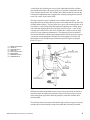
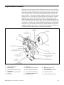
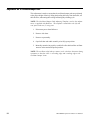
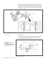
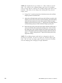
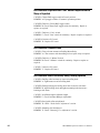
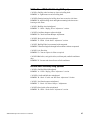
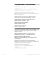
Operating and Service Manual
Ballworx
Advanced Polishing System
November 2000 /14-900075-000
Statement of Intent
This manual is provided to be used by qualified bowling center
personnel. Customer accepts responsibility for safety training of all
personnel who operate, service, or maintain this product.
Ballworx Advanced Polishing System Operating and Service Manual
© November 2000 by the Brunswick Bowling and Billiards Corporation. All rights reserved.
Reorder Part No. 14-900075-000
Notice: If available, updates to this manual can be found on-line at www.centermaster.com.
Confidential proprietary information. All information contained in this document is subject to change without notice.
Do not reproduce or disclose without the written consent of the Brunswick Indoor Recreation Group.
Brunswick Indoor Recreation Group
525 West Laketon Avenue
P.O. Box 329
Muskegon, MI 49443-0329
U.S.A.
231.725.3300
Warranty and Service Policy
Warranty
If any defects in materials appear during the 12 months after installation, the
defective part will be repaired or replaced at Brunswick’s option, without charge
to the Customer for parts. The Purchaser must assume all other costs in
making the repair or replacement.
NORMAL MAINTENANCE PROCEDURES AND ADJUSTMENTS ARE
THE RESPONSIBILITY OF THE CUSTOMER AND ARE NOT COVERED
UNDER THE TERMS OF THIS WARRANTY.
Brunswick reserves the right to change the design of any product, but assumes
no responsibility to incorporate such design changes on products already sold.
This warranty applies only to new products and extends only to the original
purchaser. This warranty shall not apply to any machine repaired or altered in
any way outside of our factory-authorized service station and/or distributor, or
where parts, other than Brunswick-approved parts, have been installed in the
machine, or where the machine has been subject to misuse, negligence, accident,
or abuse. Brunswick reserves the right to inspect and make the final decision on
any claim under this warranty that it deems questionable.
Under no circumstances shall the seller or manufacturer be liable for loss of
profits or other direct or indirect costs, expenses, losses, or damages arising out
of defects in, or failure of the equipment, or of the parts.
During the warranty period, parts that are faulty due to material or workmanship
will be repaired or replaced free of charge only if the defective part is properly
identified and returned for credit. A Brunswick Product Trouble Report must be
completed, including a description of the problem, and the completed form must
accompany the returned part. A returned goods number must be obtained from
Brunswick prior to returning any items. Identify the returned part by attaching a
tag containing the part name and part number.
The above warranty is exclusive: THERE ARE NO IMPLIED WARRANTIES,
INCLUDING MERCHANTABILITY AND FITNESS FOR USE, beyond
those expressly made herein.
Any warranty claim must be preceded by a phone call to a Technical Support
Engineer who will assist the customer with troubleshooting procedures prior to
the filing of any warranty claim. For Ballworx, call 231-725-4637 or 231-7254972 or FAX 231-725-4677.
.
Motor Warranty
The electric motors are guaranteed by the motor manufacturers for a period of
one year from the date of delivery to purchaser. If the motors develop any
defect in material or workmanship during the one-year warranty period, they will
be repaired or replaced free of charge, at Brunswick’s option. The Purchaser
must assume all other costs in making the repair or replacement.
Obtaining Warranty Service For Parts
In order to obtain warranty service for defective parts, the Purchaser must
purchase from Brunswick, a part to replace the defective part and then return
the defective part with a Product Trouble Report and the replacement part
invoice to Brunswick’s service center at 525 W. Laketon Avenue, Muskegon,
MI 49443, freight prepaid. Upon determination that the returned part is defective, Brunswick will credit Purchaser’s account for the purchase price of the
replacement part purchased by Purchaser.
Service Parts
Refer to the bowling section of the BRUNSWICK PARTS CATALOG for
parts identification. Service parts may be ordered through your Brunswick
representative. When ordering service parts, specify part numbers and description to simplify handling. USE ONLY GENUINE BRUNSWICK SERVICE
PARTS
Contents
Section 1: General Information ..................................................................... 1
Introduction ....................................................................................................... 1
Installation and Set-Up ..................................................................................... 2
Machine Placement ....................................................................................... 2
Programming .............................................................................................. 2
Operation .......................................................................................................... 3
Section 2: Component Description ............................................................... 4
Frame and Motor .............................................................................................. 4
Buffing Wheel Mechanism ............................................................................... 4
Ventilation System ............................................................................................ 6
Ball Roller Mechanism ..................................................................................... 7
Oscillator Mechanism ....................................................................................... 8
Cradle and Ball Door Mechanism ...................................................................10
Compound Advance Mechanism ..................................................................... 11
Electrical System and Control Box ..................................................................14
Overview ......................................................................................................14
Motor ............................................................................................................14
Control Box Circuit Breaker ........................................................................14
Control Box Buffing Motor Relay ................................................................14
Control Box Buffing Motor Relay Houseball Toggle Switch .......................14
Printed Circuit Board (PCB) ...........................................................................15
Start Button (Customer Display) .....................................................................15
LCD Screen (Customer Display) ....................................................................15
External Microswitch .......................................................................................16
Door Closed Switch .....................................................................................16
1 Minute Pulse Switch ..................................................................................16
Sold Out Switch ............................................................................................16
Scrolling Message Display ...............................................................................16
Bill Acceptor ....................................................................................................17
Bill Acceptor (US Machines Only): .............................................................17
Coin Mechanism ..............................................................................................17
Programmable Coin Mechanism ..................................................................17
Section 3: Adjustments .................................................................................. 18
Adjustment No. 1 Mounting Feet ....................................................................18
Adjustment No. 2 Steel Guide Rollers .............................................................19
Adjustment No. 3 Buffing Wheel ....................................................................20
Adjustment No. 4 OscillatorBumper Pads ......................................................22
Adjustment No. 5 Belt Tracking and Tension ..................................................26
Adjustment No. 6 Cradle and Ball Door Assembly ........................................28
Adjustment No. 7 Bevel Gears ........................................................................29
Section 4: General Maintenance ................................................................. 30
Replacement of Buffing Compound ................................................................30
Replacement of Buffing Wheel .......................................................................32
BALLWORX Operation and Service Manual
i
Section 5: Preventive Maintenance ............................................................ 36
Bi-Monthly .......................................................................................................36
Monthly ............................................................................................................36
Section 6: Electrical ....................................................................................... 37
Section 7: Programming ................................................................................ 39
Control Box ......................................................................................................39
Controls: .......................................................................................................39
Operation: .....................................................................................................39
To Display Data: .......................................................................................39
Function Buttons: .......................................................................................39
To Program Data: .....................................................................................39
PROGRAMMING Buttons: .....................................................................39
Programming ................................................................................................40
Setting Gloss Level Values: .......................................................................40
Setting Coin Values: ..................................................................................40
Setting House Ball Run Time: ...................................................................40
Utilizing Clear Button: ...............................................................................40
Metering Functions: ...................................................................................40
Programmable Coin Mechanism .....................................................................41
Controls ........................................................................................................41
Enable Coin ..................................................................................................42
Disable Coin .................................................................................................42
Program Multiple Coins ................................................................................42
Programming Theory: ...................................................................................43
Scrolling Message Display ...........................................................................43
Section 8: Troubleshooting ........................................................................... 44
Ball Conditioner Inoperable - Power to PC Board .......................................44
Ball Conditioner Inoperable - No Power to PC Board .................................45
Buffing Cycle Will Not Start When Ball Door is Closed ..............................45
Ball Conditioner is Operable When "Start" button is Depressed and No
Money is Deposited. .....................................................................................46
Ball Conditioner Continues to Run ...............................................................46
Ball Conditioner Vibrates Excessively During Polishing Operation .............46
Ball Conditioner Will Not Polish Bowling Ball Properly ...............................47
Ball Door Moves Excessively During Operation .........................................47
Customer Display Inoperable or Displays Wrong Information .....................48
Programmable Coin Mechanism Will Not Accept and/or Register (Coins) .48
Internal "Stacking" Bill Acceptor Will Not Accept and/or Register (Bills) ..49
ii
BALLWORX Operation and Service Manual
Section 1: General Information
Introduction
The Brunswick Ballworx Advanced Polishing System is an automatic bowling
ball polishing machine, which offers 1 to 4 polishing levels with time & money
determined by the Proprietor programming Ballworx.
The polishing levels are determined by the amount of money deposited in the coin
and/or bill acceptor slots and are explained on the customer display adjacent to
the coin and/or bill acceptor slots.
Ballworx consists, in part of a high-speed cotton buffing wheel that polishes the
bowling ball, a ball roller mechanism that constantly rotates the bowling ball, and
an oscillator mechanism that constantly changes the position of the bowling ball
against the buffing wheel. A polishing compound block is used that intermittently
applies polishing compound material to the buffing wheel. The buffing wheel, ball
roller, oscillator, and compound block are driven by a double-ended, one-horse
power electric motor.
The ball door is mounted on the front panel and is opened by the customer at the
beginning of each operation to accept a bowling ball. The ball door is then closed
by the customer and remains closed during the entire operation of the machine.
The ball door is then reopened by the customer at the completion of operation to
allow the customer to remove his/her polished bowling ball.
A blower, driven by the one-horse power motor, forces air upward through the
polishing compartment, through an air filter on the bottom side of the top panel,
and through vents in the top panel. The forced air, removes polishing material
and dust form the polishing compartment and insures that the bowling balls will
be free from polishing material and dust at the completion of the machine’s
operation.
A Liquid Crystal Display (LCD) on the Customer Display indicates the information needed for customer use, including (Pricing, Time, Money Deposited, and
Time Remaining). A start button initiates machine operation once money has
been deposited.
BALLWORX Operation and Service Manual
1
Installation and Set-Up
Machine Placement
1.
Position Ballworx in its permanent location.
2.
Level Ballworx (refer to "Mounting Feet Adjustment" section on page
18).
3.
Insert power plug into the grounded receptacle. (The power cord
provided with Ballworx is an approved three-prong plug.)
NOTE: The grounded receptacle provided for Ballworx must be on a
dedicated 208/230 VOLT 20 AMP breaker.
4.
Ballworx is now is ready for test operation.
Programming
Ballworx has been programmed at the factory with pricing and time values. If
these settings are not acceptable, they can be changed. (Refer to the "Programming" section beginnig on page 39)
2
BALLWORX Operation and Service Manual
Operation
The operation of Brunswick Ballworx Advanced Polishing System is as follows:
The customer decides which polishing level is desired, and then deposits the
appropriate amount of money as explained on the customer display. When the
proper amount has been deposited, the ball door is opened, the bowling ball is
inserted, and the ball door is closed. Then the customer depresses the “START”
button on the customer display.
When the “START” button is depressed, Ballworx, through its control PCB,
selects the proper polishing level, and starts the one-horse power motor.
During the polishing operation, the bowling ball is held against the cotton buffing
wheel and rests on a slow turning, urethane ball roller to prevent the bowling ball
from spinning at the same speed as the buffing wheel. The difference in speed
between the bowling ball and the buffing wheel produces a friction buffing
effect.
A compound advance mechanism moves the polishing compound material
momentarily against the buffing wheel once during each minute of operation.
The controlled application of the compound material to the buffing wheel insures
that the proper amount of compound material is used during the polishing operation.
A constantly rotating oscillator arm changes the position of the bowling ball
during the polishing operation to apply a uniform polish to the whole bowling ball.
At the completion of the polishing operation, the one-horse power motor stops.
The customer then opens the ball door, removes his/her bowling ball, and then
closes the ball door.
Ballworx is now ready for the next customer to use.
The theory of operation, adjustments, troubleshooting, maintenance, and houseball operation will be explained in subsequent sections of this manual. This
manual should be read carefully and all procedures followed to obtain optimum
performance of the Brunswick Ballworx Advanced Polishing System.
BALLWORX Operation and Service Manual
3
Section 2: Component Description
Frame and Motor
The Ballworx frame is constructed of reinforced sheet metal and consists of two
side frames, a lower frame and back panel. Two parallel brackets extend across
the front and rear of the lower frame. Four screw-type adjustable mounting feet
are threaded into the brackets at the four corners of the machine and are used to
level and stabilize the position of Ballworx.
The buffing wheel and bowling ball compartments are located between the side
frames with baffles between them for separation. The upper polishing compartment is relatively airtight when the top cover is in position, except for a large
opening in the center baffle. During polishing operation a portion of the bowling
ball protrudes into the buffing compartment through the circular opening. The
bowling ball compartment is located in front of the buffing compartment and
houses the bowling ball during polishing operation.
Buffing Wheel Mechanism
Attached to the inside of both the right and left-hand side frames is the buffing
wheel assembly, which includes a dual supported shaft. This shaft protrudes
through a bearing housing and the right-hand side frame, it also attaches to a
pillow block bearing and bracket mounted on the left-hand side frame. Refer to
Figure 1.
Figure 1. Buffing Wheel
4
BALLWORX Operation and Service Manual
The buffing shaft rotates counter clockwise at high speed (3000 rpm) and is
driven by a Linkable ‘V’-belt from the large pulley on the one horse power
motor, to the small pulley on the buffing shaft. Both pulleys are keyed to their
respective shafts.
The buffing wheel assembly is mounted on the buffing shaft and consists of
seven individual sections of cotton buffing material attached to seven separate
metal hubs. Metal spacers that are positioned on the buffing shaft separate the
seven sections of the buffing wheel. The entire buffing wheel assembly is
secured to the buffing shaft by a pair of jam nuts. These nuts have left-hand
threads.
The buffing wheel mechanism mounting holes are slotted to allow adjustment of
the buffing wheel assembly as the cotton buffing material wears. A slide plate
and adjusting screw are mounted on the outside of the right-hand side frame and
are attached to the buffing wheel mechanism. (Refer to "Buffing Wheel Adjustment" section on page 20)
A linkable belt drives the buffing wheel from the motor pulley. This belt is made
up of small links, which are removable to increase or decrease belt tension.
(Refer to "Belt Tension Adjustment" section on page 26)
BALLWORX Operation and Service Manual
5
Ventilation System
Brunswick Ballworx employs a forced air ventilation system through the ball
compartment and buffing compartment to insure that all dirt and dust is removed
from the bowling ball during polishing operation. Refer to Figure 2.
(1)
(2)
(3)
(4)
(5)
(6)
(7)
(8)
(9)
(10)
(11)
OPENINGS IN TOP PANEL
AIR FILTER
BUFFING COMPARTMENT
BUFFING WHEEL
AIR DUCT
BLOWER HOUSING
SHAFT FROM MOTOR HOUSING
BLOWER WHEEL
BALL COMPARTMENT
CENTER BAFFLE
TOP PANEL
Figure 2. Overview of Ventilation System
A blower wheel is attached to the right-hand end of the shaft from the one horse
power motor. A sheet metal housing covers the blower wheel and directs the air
upward, through an air duct, and into the bowling ball compartment.
During the polishing operation, the bowling ball protrudes through the circular
opening in the center baffle as previously described. Since the bowling ball
compartment is basically airtight, the air that is forced into the bowling ball
compartment escapes into the buffing wheel compartment. Air passes between
them at high velocity, thus removing all dirt and dust from the bowling ball. The
only escape route for the dust-laden air is through an air filter attached to the
bottom of the top cover. The dust-laden air is forced through the air filter and
deposits the impurities in the air filter, then passes through openings in the top
cover.
The blower wheel starts to turn when the ball door is closed and the "Start"
button is depressed at the start of the polishing operation, and stops turning when
the ball door is opened and/or at the completion of the polishing operation.
6
BALLWORX Operation and Service Manual
Ball Roller Mechanism
Mounted to the inside surface of the left-hand side frame is a bearing housing,
which houses a bearing at each end. The housing supports the ball roller shaft
that extends from the bowling ball compartment through the left-hand side frame.
Refer to Figure 3.
(1)
(2)
(3)
(4)
(5)
(6)
(7)
(8)
(9)
(10)
BALL ROLLER SHAFT
URETHANE BALL ROLLER
BEARING HOUSING
LEFT-HAND SIDE FRAME
FLAT BELT (DRIVEN FROM
BUFFING MOTOR)
TRIANGULAR HUB
PINION SPROCKET
LARGE PULLEY
DRIVE CHAIN TO OSCILLATOR
MECHANISM
1 HP MOTOR PULLEY
Figure 3. Ball Roller Mechanism
The inside end of the ball roller shaft carries the urethane ball roller, on which the
bowling ball rides during the polishing operation. The function of the ball roller is
to rotate at a slower speed than the buffing wheel and consequently prevent the
bowling ball from spinning at the same rate of speed as the buffing wheel. The
urethane ball roller also supports the weight of the bowling ball while being
polished.
When the ball door closes, the weight of the bowling ball is transferred from the
door cradle to the ball roller. The bowling ball, in its polishing position, rests on
the ball roller and a steel roller at the bottom of the opening in the center baffle.
At this time the bowling ball also contacts the buffing wheel and steel ball door
roller. Two steel rollers, one attached to each side frame, restrict the lateral
movement of the bowling ball during the polishing operation.
The ball roller consists of a urethane cylinder that is bonded to a metal sleeve.
The ball roller assembly is keyed to the ball roller shaft and is secured by a bolt
to the end of the shaft.
The exterior end of the ball roller shaft carries a triangular hub that is keyed to
the shaft. A large circular pulley is bolted to the inside surface of the hub and
carries a flat belt that is driven by a small pulley attached to the one horse power
motor. The reduction ratio of the pulley diameter causes the ball roller shaft to
be driven at a slow speed.
A small pinion sprocket is keyed to the exterior end of the ball roller shaft and is
secured by a bolt and set screw to the end of the shaft. The pinion sprocket
drives the oscillator mechanism.
BALLWORX Operation and Service Manual
7
Oscillator Mechanism
A bearing housing is mounted to the inside surface of the left-hand side frame to
provide support for the oscillator pinion shaft. The oscillator pinion shaft extends
through the left-hand side frame, directly under the buffing wheel compartment.
Refer to Figure 4.
Figure 4. Ball Mechanism Overview
(1)
(4)
(7)
(10)
(13)
ADJUSTING NUT
BEARING HOUSING
BUMPER ADJUSTING BOLTS
DRIVE SPACER
DRIVE CHAIN TO COMPOUND
APPLICATOR MECHANISM
(16) LARGE BEVEL GEAR
(2)
(5)
(8)
(11)
(14)
SPIRAL PIN
ADJUSTABLE RUBBER BUMPERS
HORSEHAIR BRUSH
PINION SPROCKET
OSCILLATOR PINION SHAFT
(3)
(6)
(9)
(12)
(15)
OSCILLATOR DRIVE SHAFT
OSCILLATOR ARMS
CENTER BAFFLE
SPROCKET WHEEL
BEVEL PINION GEAR
(17) DRIVE CHAIN FROM BALL ROLLER
SHAFT
A large sprocket wheel and a smaller pinion sprocket gear are attached to the
left end of the oscillator pinion shaft. The large sprocket gear has a radial key
slot across its exterior face that aligns with an identical radial slot in the end of
the shaft. A drive spacer, having a radial key surface on each of its faces,
engages the key slots of the sprocket wheel and shaft, thus locking them together. The drive spacer, pinion sprocket wheel are secured to the oscillator
drive shaft with a bolt and lock washer.
The oscillator pinion shaft is powered through the large sprocket wheel by a
drive chain that is driven by the pinion sprocket on the ball roller shaft. As the
drive chain rotates the large sprocket wheel, the force is transmitted to the shaft
and sprocket gear through the radial keys on the drive spacer, thus rotating the
pinion sprocket and oscillator pinion shaft.
8
BALLWORX Operation and Service Manual
A small nylon bevel pinion gear is keyed to the right-hand end of the oscillator
pinion shaft and meshes with a large nylon bevel gear that is mounted to the end
of the oscillator pinion shaft. The oscillator drive shaft extends forward into the
bowling ball compartment and is supported by a bearing housing that is mounted
to the rear surface of the center baffle
The large nylon bevel gear is attached to the oscillator shaft assembly. An
adjusting nut having six horizontal projections, is threaded onto the rear end of the
oscillator shaft assembly. The large nylon bevel gear, with six mating holes on its
forward face, is positioned on the shaft against the adjusting nut, with the projections of the nut engaging the holes in the large nylon bevel gear. A pair of jam
nuts and a flat washer on the end of the oscillator drive shaft secures the large
nylon bevel gear against the adjusting nut. The adjusting nut can be threaded
forward or backward to obtain proper alignment between both nylon bevel gears.
A spiral pin inserted though the oscillator drive shaft engages two slots in the
adjusting nut to lock the adjusting nut when the nylon bevel gears are aligned.
Refer to Figure 5.
(1)
(2)
(3)
(4)
(5)
(6)
(7)
(8)
BEVEL PINION GEAR
JAM NUTS
ADJUSTING NUTS
SPIRAL PIN
OSCILLATOR SHAFT
PINION GEAR
BEARING HOUSING
CENTER BAFFLE
Figure 5. Oscillator Shaft
When the oscillator pinion shaft is rotated, as previously described, the motion is
transferred from the small nylon pinion bevel gear to the large nylon bevel gear,
which, through the projections on the adjusting nut, rotates the oscillator drive
shaft assembly.
The reduction ratio between the small and the large nylon bevel gears causes the
oscillator drive shaft assembly to rotate slower than the oscillator pinion shaft.
BALLWORX Operation and Service Manual
9
Two oscillator arms are keyed to the forward end of the oscillator drive shaft,
separated by two spacers and a horsehair brush. The oscillator arms straddle
the ball roller. A urethane oscillator bumper pad is clamped to each oscillator
arm and, as the oscillator shaft rotates, the bumper pads will contact the bowling
ball once per revolution. When the oscillator bumper pads contact the bowling
ball, the bowling ball will be momentarily lifted and rotated, thereby constantly
changing the position of the bowling ball against the buffing wheel. Since the
oscillator mechanism is powered indirectly by the one horsepower motor, the
oscillator mechanism rotates only when the ball door is closed during a polishing
operation.
The horsehair brush is mounted on the oscillator shaft assembly, directly under
the urethane ball roller. As the oscillator assembly rotates, the brush contacts
the urethane ball roller and keeps it clean to prevent marking of the bowling balls
being polished.
Cradle and Ball Door Mechanism
The cradle and ball door mechanism located in the center of the front panel is
where the customer will place the bowling ball. The customer opens the ball
door to access the cradle assembly, and places the bowling ball onto the cradle
in the center of the ball door. The cradle assembly has four (4) idler rollers that
the bowling ball rests on until the ball door is closed. The cradle assembly also
has one (1) spring loaded steel guide roller to hold the bowling ball against the
buffing wheel.
10
BALLWORX Operation and Service Manual
Compound Advance Mechanism
Mounted to the exterior surface of the left-hand side frame, above the oscillator
drive shaft, is another bearing housing that contains a reducer shaft. The outside
end of the reducer shaft carries a large sprocket gear that has a radial key slot
across its exterior face. This radial key slot aligns with an identical slot in the
end of the shaft. A drive spacer having a radial key surface on each of its faces
engages the key slot of the sprocket gear and shaft, thus locking them together.
Mounted on the extreme end of the reducer shaft is a small pinion sprocket,
which also has radial key slot across its hub. This slot engages the opposite key
surface of the drive spacer to lock the small pinion sprocket to the large sprocket
gear and shaft. The drive spacer and small pinion sprocket gear are mounted on
a bolt that is screwed into the end of the shaft. The bolt holds the keyed slots in
engagement with the drive spacer. A roller chain drives the large sprocket gear
from the small pinion sprocket gear on the oscillator pinion shaft.
Figure 6. Compound Advance Mechanism
(1) COMPRESSION SPRING
(4) DRIVE HOUSING
(7) DRIVE CHAIN FROM OSCILLATOR
MECHANISM
(10) COMPOUND APPLICATOR SWITCH
(CAST)
(13) "Y" SHAFT
BALLWORX Operation and Service Manual
(2) DRIVE HUB
(5) COMPOUND APPLICATOR CAM
(3)
(6)
PIN
BEARING HOUSING FOR
REDUCER SHAFT
REDUCER PINION SPROCKET
(8) REDUCER SPROCKET WHEEL
(9)
(11) BOLT HEAD THAT CONTACTS
MICROSWITCH LEVER (CAST)
(14) REDUCTION GEARS
(12)
TRIANGULAR PLATE
(15)
CIRCULAR CAM FOLLOWER
11
Mounted to the exterior surface of the left-hand side frame, directly above the
reducer sprocket, are two parallel triangular plates. The two plates are held apart
by two cylindrical spacers and mounting bolts that attach the triangular plates to
the side frame. These two bolts and spacers serve as stationary pivot shafts for
the sprockets, cams and gears that are mounted between the triangular plates.
These two shafts will be referred to as “X” and “Y”. Mounted on shaft “X”,
immediately under the outside plate, is a sprocket wheel which has two rivets
that protrude inward and engage two holes in the circular compound applicator
cam that is freely mounted on the “X” shaft. (Figure 7). Freely mounted on the
“X” shaft are two additional gears, each having one large diameter gear and a
small diameter pinion gear. Mounted on the “Y” shaft are three more combination gears, each having one large diameter gear and a one small pinion gear. As
the buffing motor turns, the large sprocket wheel is rotated by the reducer pinion
sprocket, which also rotates the compound applicator cam. The meshing of the
five additional gears on the “X” and “Y” shafts form a reduction gear train
which causes the last gear on the “Y” shaft to turn at the lowest speed.
A split plate drive housing is freely mounted on the “Y” shaft and straddles the
three gears mounted on the “Y” shaft. The drive housing carries the compound
shaft that extends through a circular hole in the left-hand side-frame and into the
buffing compartment. The inside end of the compound shaft carries the buffing
compound which is keyed to the compound drive shaft by means of a drive hub
and a pin that projects into the compound material. A compression spring
between the left-hand frame and the drive hub keeps the projection in the hole of
the compound material. When the compound drive shaft turns, the motion is
transmitted to the compound material through the drive hub, which turns the
compound material. A washer and thumbscrew secure the compound material
to the inside end of the compound shaft.
A gear hub is attached to the compound shaft between the arms of the drive
housing. The hub carries a circular spur gear that is driven by the reduction gear
train from the reducer sprocket. A circular cam follower is also mounted on the
compound drive shaft, separated from the circular gear and hub by a spacer. A
tension spring is attached to the forward end of the drive housing to urge the
circular cam follower against the compound applicator cam. The compound
applicator cam has a low dwell for approximately 90 degrees of its circumference. As the circular cam follower engages the low dwell in the compound
applicator cam, the tension spring pulls downward on the drive housing, thus
pivoting the compound material against the buffing wheel. Then, as the circular
cam follower engages the high level of the compound applicator cam, the drive
housing is pushed upward to move the compound material away from the buffing
wheel. The compound applicator cam rotates at approximately one revolution
per minute. The buffing compound material is applied against the buffing wheel
one time per minute during the polishing cycle.
12
BALLWORX Operation and Service Manual
A “Sold Out” microswitch that has an actuating lever and roller is mounted on
the inside surface of the drive housing. The circumference of the gear hub has a
low dwell for 45 degrees of its circumference. The gear hub and compound
material rotate on the drive shaft and consequently, when the shaft has made one
revolution. The compound is no longer usable. The actuator lever on the “Sold
Out” switch will find the low dwell in the gear hub and close the switch to
indicate electrically that the compound material is depleted refer to Figure 7.
When the switch closes, the customer display will register “Sold Out” and lock
out both the coin mechanism and dollar bill acceptor. The compound material
must then be replaced. Refer to the "Repacement of Buffing Compound"
sections
Figure 7. "Sold Out" Switch
(1) COMPOUND MATERIAL
(2)
(4) GEAR HUB HAS SURFACE THAT
(5)
CONTROLS "SOLD OUT" SWITCH
(7) COMPOUND APPLICATOR COMPOUND (8)
(10) DRIVE CHAIN
(11)
(13) REDUCER GEARS
"SOLD OUT" SWITCH
CIRCULAR CAM FOLLOWER
TRIANGULAR PLATE
"X" SHAFT
(14) "Y" SHAFT
(3)
(6)
(9)
(12)
(15)
DRIVE HOUSING
GEAR THAT ROTATES COMPOUND
APPLICATOR SHAFT
COMPOUND APPLICATOR SWITCH
BOLT HEAD THAT CONTACTS
MICROSWITCH LEVER (CAST)
COMPOUND APPLICATOR SHAFT
A “One Minute Pulse” microswitch that is attached to an “L” shaped bracket is
mounted on the outside of the triangular plate. The actuator lever for the switch
protrudes through an elongated opening in the triangular plate and contacts the
outside surface of the sprocket gear. The sprocket gear carries a button head
screw that contacts the switch once per revolution. Since the sprocket gear
rotates one revolution per minute, the switch is depressed once each minute.
The switch indicates electrically each minute of elapsed time during a polishing
cycle.
BALLWORX Operation and Service Manual
13
Electrical System and Control Box
Overview
The Brunswick Ballworx operates on 208/230 Volts AC, 50/60 HZ single-phase
power. A transformer is used to supply 115 Volts AC and 16 Volts AC to the
control systems. The PC Board rectifies the power and supplies 12 volts DC to
the Bill Acceptor as well as the optional Programmable Coin Validator.
Motor
An integral, automatic resetting, thermal overload device protects the motor.
Control Box Circuit Breaker
The control circuitry is protected by a 2 amp re-settable circuit breaker mounted
on the left-hand side of the electrical box.
Control Box Buffing Motor Relay
The buffing motor relay, when energized, closes two sets of contacts, (R3 & R1)
and (L3 & L1) on the buffing motor relay. (Reference wiring schematic on page
36 ) When contacts (R3 & R1) and (L3 & L1) on this relay are closed, the one
horsepower motor is powered and the motor starts. At the end of the polishing
operation, (R3 & R1) and (L3 & L1) on the relay open and a third set of contacts, (R4 & R1) and (L4 & L1), also on this relay, close, putting a reverse
current across the reverse motor windings, thus acting as a motor brake.
Control Box Buffing Motor Relay Houseball Toggle Switch
The house ball toggle switch is a single pole, two-position switch. In its normal
coin operated position, Ballworx will operate when coins are deposited for the
programmed cycles. It is always left in this position for customer operation. For
house ball cleaning the switch is put to the “Houseball” position, which registers
on the customer display, and gives the programmed cycle when the start button
is depressed.
14
BALLWORX Operation and Service Manual
Printed Circuit Board (PCB)
ThePrinted Circuit Board (PCB) controls the operations of Ballworx. The
(PCB) is the information center and translates all the signals from and to the
external components. The (PCB) is where the owner/operator programs the
pricing and time levels for the customer usage.
No attempt should be made to repair a Printed Circuit Board in the field. This
will void the warranty on the (PCB). Replacement Printed Circuit Boards are
available from Brunswick. (Follow the return policy in the "Warranty" section in
the front of book)
Start Button (Customer Display)
The start button is a momentary contact push button switch that makes contact
when it is manually depressed. When pressure is removed, the push button
switch returns to its open position.
LCD Screen (Customer Display)
The Customer Display is a Liquid Crystal Display (LCD); it is a two-segment
12-character display. The information programmed from the (PCB) will register
on this display, making it adaptable for any pricing and/or time structure. This
screen gives all the information the customer will need to determine the polishing
level.
BALLWORX Operation and Service Manual
15
External Microswitch
Door Closed Switch
The Door Closed Switch is a single pole, double throw microswitch that is
mounted on the exterior right-hand side frame and is controlled by the ball door
mechanism. When the ball door is open, the switch is deactuated and its normally open (N/O) contacts are open. When the ball door is closed, the switch is
actuated and its (N/O) contacts are closed. No connection is made to the
normally closed (N/C) terminal of the switch. This switch is connected to the
(PCB) in series with the buffing motor relay and will permit the motor to operate
only when the ball door is closed.
1 Minute Pulse Switch
The 1 Minute Pulse Switch is a single pole, double throw microswitch that is
mounted to the triangle plate of the compound advance mechanism, and is
controlled by the button head screw on the timing sprocket. When the button
head screw is not in contact with the switch, the switch is deactuated and its
normally open (N/O) contacts are open. When the button head screw is in
contact with the switch, the switch is actuated and its (N/O) contacts are closed.
No connection is made to the normally closed (N/C) terminal of the switch. This
switch is connected to the (PCB) and counts down the time remaining for a
polishing level.
Sold Out Switch
The Sold Out Switch is a single pole, double throw microswitch that is mounted
to the compound shaft on the compound advance mechanism, and is controlled
by a cam on the compound shaft. When the high of the cam contacts the switch,
the switch is actuated and its normally closed (N/C) contacts are closed. When
the low dwell of the cam allows the switch roller arm to move away from the
switch, the switch is deactuated and its (N/C) contacts are open. No connection
is made to the normally open (N/O) terminal of the switch. This switch is
connected to the (PCB) and shuts down the operation of the machine until
compound material is replaced.
Scrolling Message Display
The Scrolling Message Display is mounted to the back frame of Ballworx. It is a
programmable message display, which accepts programming from a remote
controller or integrated computer cable. This sign is capable of displaying
multiple messages including but not limited to (advertising, special events,
bowler’s scores). Refer to the promotion handbook for more information.
16
BALLWORX Operation and Service Manual
Bill Acceptor
Bill Acceptor (US Machines Only):
The Internal Bill Acceptor with Stacker is mounted on the left-hand side of the
front panel. This bill acceptor is capable of accepting ($1, $5, $10, $20, $50, &
$100) dollar bills but is factory switched to accept $1 bills only. The dip switches
on the top of the bill acceptor control which bills it will accept. The stacker box
on the back of the bill acceptor will hold a maximum of 400 bills. It also has a
separate lock for access to the bills. The bill acceptor is mounted by 2 wing nuts
accessible through the left service panel. A phone jack style cable, connects the
bill acceptor to the (PCB). Ballworx will not give change.
Coin Mechanism
Programmable Coin Mechanism
The Programmable Coin Mechanism can accept any type of coin in the world
including tokens in multiple denominations. The coin mechanism is mounted to
the right-hand side of the front panel and has a keyed lock for easy access to
clear coin jams. The coin mechanism is connected to the (PCB) by a ribbon
cable that transfers all the information needed to operate.
BALLWORX Operation and Service Manual
17
Section 3: Adjustments
IMPORTANT!: When servicing Brunswick Ballworx, the power cord must
be disconnected from the power source to prevent injury to personnel.
Adjustment No. 1 Mounting Feet
This adjustment is made to insure that Ballworx is level and supported on all four
(4)-mounting feet to avoid unnecessary vibration and for proper ball polishing
performance. Refer to Figure 8.
(1) ADJUSTING NUTS
(2) MOUNTING FEET
Figure 8. Mounting Feet
18
1.
With Ballworx positioned in its operational location, remove both sidedoors.
2.
Place a carpenter’s level across the flat surface of the top panel.
3.
Loosen the two (2) nuts on each mounting foot.
4.
Adjust each mounting foot until Ballworx is level from side to side and
front to rear.
5.
Check each mounting foot to be certain that all four (4) mounting feet
support the weight of Ballworx.
6.
Securely tighten both nuts on each mounting foot.
7.
Replace both side-doors.
BALLWORX Operation and Service Manual
Adjustment No. 2 Steel Guide Rollers
This adjustment is made to ensure that the guide rollers are positioned properly to
restrict the motion of the bowling ball during the polishing operation, and that the
bowling ball is centered to the buffing wheel.
NOTE: The Steel Guide Roller Adjusting Template, used in this adjustment,
is supplied with Ballworx. The template is attached to the left side of the
back panel with two (2) wing nuts. Refer to Figure 9.
Figure 9. Roller Adjusting Template
(1) LONG SIDE OF TEMPLATE
BALLWORX Operation and Service Manual
1.
Disconnect power from Ballworx.
2.
Remove side doors.
3.
Remove top assembly.
4.
Access steel guide roller template form Ballworx. This is the “L”shaped right-angle template. There is a long and short side to this
template. See illustration below
5.
Open ball door
6.
Place template onto the steel guide rollers, mounted to the sides of the
ball compartment, with the long side to the left-hand side roller.
7.
Adjust guide rollers so that both guide rollers are flush with template and
the template is held firmly against the right-hand side frame.
8.
Replace top assembly, side doors, and return power to Ballworx.
19
Adjustment No. 3 Buffing Wheel
This adjustment is required to maintain adequate pressure and contact area
between the bowling ball and the buffing wheel as the buffing wheel becomes
worn though normal use or when installing a new buffing wheel. To maintain
proper polishing performance, it is recommended that the buffing wheel adjustment be checked whenever the compound is replaced.
NOTE: The buffing wheel adjusting template used in this sequence, is
supplied with the ball conditioner. The template is attached to the left side
rear panel with two (2) wing nuts.
20
1.
Disconnect power from Ballworx.
2.
Remove side doors.
3.
Remove top assembly.
4.
Open ball door and cradle assembly to its fully open position.
5.
Remove the linkable drive belt from the upper pulley.
6.
Using a ½ inch wrench, loosen the four (4) bolts that secure the buffer
shaft bearing housing to the right-hand side frame and the two (2) bolts
that secure the pillow block bearing to the pillow block bracket.
BALLWORX Operation and Service Manual
7.
Position the template inside the ball compartment with point “A” on the
center of the rubber brake roller and point “B” against the metal roller
beneath the buffing wheel (Figure 10A). On the outside of the righthand side frame is an easy adjust bracket with jackscrew and locknut.
Loosen the locknut and rotate the jackscrew moving the entire buffing
wheel assembly forward or rearward until the narrowest portion of the
buffing wheel just touches the edge of the template at point “C”. Tighten
the locknut on the jackscrew. Rotating the jackscrew 1 complete revolution moves the buffing wheel assembly 1/32 of an inch. It is recommended to move the buffing wheel assembly forward 1/32 of an inch or,
one complete turn clockwise, each time a new buffing wheel compound
block is installed. Refer to Figure 10B.
A
B
Figures 10A & 10B. Buffing Wheel Adjustment
(1) BEARING HOUSING BOLTS
(4) OSCILLATOR RUBBER BUMPERS
(2) ROLLER
(3)
(5) BUFFING WHEEL ADJUSTING TEMPLATE (6)
RUBBER BRAKE ROLLER
JACK SCREW
8.
Tighten the four (4) bolts for the bearing housing first and the shaft will
self align with the frame of the machine, then tighten the two (2) bolts
for the pillow block bearing.
9.
Replace drive belt, top assembly, side doors, and return power to
Ballworx.
NOTE: Always test, a bowling ball in Ballworx after making any adjustment. After a 2-minute cycle a bowling ball should come out of Ballworx
slightly warm.
BALLWORX Operation and Service Manual
21
Adjustment No. 4 OscillatorBumper Pads
This adjustment is made to ensure that the oscillator bumper pads are positioned
at the proper height effectively lifting the bowling ball away from the buffer, off
the ball roller, and rotating the bowling ball during the polishing cycle.
NOTE: The Oscillator Bumper Pad Adjusting Template, used in this adjustment, is supplied with Ballworx. The template is attached to the left side
rear panel with two (2) wing nuts.
1.
Disconnect power from Ballworx.
2.
Remove side doors.
3.
Remove top assembly.
4.
Open ball door and cradle assembly to its fully open position.
5.
Manually rotate the large pulley on the ball roller shaft until the oscillator
arms are in the maximum upward position.
NOTE: The oscillator shaft always rotates in the clockwise direction during
operation so therefore there is a leading edge and a trailing edge to the
oscillator bumper arms.
22
BALLWORX Operation and Service Manual
6.
Manually rotate the large pulley on the ball roller shaft until the oscillator
bumper’s leading edge is aligned with the center of the ball roller and
buffing wheel. The leading edge is designated by the first screw head
that will pass by the buffing wheel when rotated in the clockwise direction. Refer to Figure 11.
Figure 11. Oscillator Bumper Pad Adjustment
(1) LEADING EDGE
(2) TRAILING EDGE
7.
(1)
(2)
(3)
(4)
(5)
Position the template inside the ball compartment with point “A” on the
center of the ball roller and point “B” against the steel guide roller
beneath the buffing wheel. Refer to Figure 12.
BEARING HOUSING BOLTS
ROLLER
RUBBER BRAKE ROLLER
OSCILLATOR RUBBER BUMPERS
BUFFING WHEEL ADJUSTING
TEMPLATE
Figure 12. Template Position
BALLWORX Operation and Service Manual
23
NOTE: The template has two (2) cutouts in it. These cutouts are not the
same. The cutout for the oscillating bumper pad closest to the buffing
wheel is deeper than the cutout for the oscillator bumper pad closer to the
ball door. This allows for the lifting of the bowling ball away from the
buffing wheel.
8.
Using a 5/16” wrench, loosen the two bolts that secure each oscillator
bumper pad to the oscillator arms.
9.
Adjust the oscillating bumper pad closest to the ball door assembly, with
template in place raise or lower the oscillator bumper pad on the leading
edge until it just touches the cutout in the template without raising the
template off the ball roller at point “A”. Snug the bolt on leading edge of
oscillator bumper pad just so that it holds the bumper pad in place.
10.
Rotate the large pulley on the ball roller shaft so that the trailing edge is
centered to the ball roller shaft and the buffing wheel. Raise or lower
the ending edge of the oscillator bumper pad so that it just touches the
cutout of the template without raising the template off the ball roller at
point “A”. Tighten ending edge bolt. Tighten both leading and trailing
edge bolts securely.
NOTE: The oscillating bumper pads holes are elongated to allow for
movement up and down. Do not over tighten the oscillator bumper pad
bolts. This will cause the bumper pads to squeeze between the oscillator
arm and clamping plate changing the height adjustment.
24
BALLWORX Operation and Service Manual
11.
Rotate the oscillator arm back to the leading edge to adjust the oscillator
bumper pad closet to the buffing wheel. Raise or lower this oscillator
bumper pad so that it just touchesthe cutout in the template. Snug the
bolt on leading edge of oscillator bumper pad, just tight enough to hold
bumper in place.
12.
Rotate the oscillator arm to the trailing edge and adjust the trailing edge
of the oscillator bumper pad so that it just touches the cut out in the
template. Tighten leading edge bolt. Refer to Figure 13.
Figure 13. Adjust Oscillator Bumper
(1) LEADING EDGE BOLT
BALLWORX Operation and Service Manual
(2) ENDING EDGE BOLT
(3)
LEADING EDGE TOUCHES
25
Adjustment No. 5 Belt Tracking and Tension
These adjustments are made to allow the proper tensioning and tracking of the
motor belts on both sides of Ballworx and to increase the life of the belts. As the
belts get older and stretch, belt tension will decrease. An adjustable drive belt is
used for the buffing wheel drive system.
1.
To increase or decrease the belt tension on the flat belt on the left side
of the machine, adjust the motor mount plate up or down with the jam
nuts on the adjusting rod at the lower back of the machine. Refer to
Figure 14.
(1) MOTOR BASE 9 PIVOT UP TO
DECREASE, DOWN TO INCREASE)
(2) UPPER LOCKNUT
(3) LOWER LOCKNUT
(4) ADJUSTING SCREW
(5) HINGED PIVOT
Figure 14. Adjust Belt Tension.
2.
Once the proper belt tension is achieved on the small flat belt for the ball
roller shaft assembly, adjust the linkable belt for the buffing wheel by
removing or adding a link to increase or decrease tension. Refer to
Figure 15.
Figure 15. Adjust belt Length
26
BALLWORX Operation and Service Manual
3.
Tracking is properly accomplished by moving the two (2) drive pulleys
on the motor shafts, in towards or out away from the motor. Position
these drive pulleys so the belts run centered on their perspective driven
pulleys. Refer to Figure 16.
(1) IN OR OUT
(2) DRIVE PULLEY
Figure 16. Adjust Tracking
BALLWORX Operation and Service Manual
27
Adjustment No. 6 Cradle and Ball Door Assembly
This adjustment is made to ensure the proper seal is obtained between the ball
door and the front panel.
1.
Disconnect power from Ballworx
2.
Open ball door and cradle to its fully open position.
3.
Remove the ball door by unscrewing the four (4) button head Allen
screws.
4.
Close cradle assembly. The outside edge of the door track should be
flush with the front panel.
5.
To adjust the cradle, use a 7/16 inch wrench to loosen the four (4) bolts
that hold the ball track to the cradle assembly and tilt the ball track so it
is flush with the front panel. Tighten bolts.
6.
Install ball door to the cradle assembly; close the ball door and cradle
assembly, check to see if the seal is flush to the front panel all the way
around the ball door. Refer to Figure 17.
NOTE: The holes in the ball track are slightly oversized to allow finetuning of the seal adjustment.
Figure 17. Adjust Ball Door
(1) BUTTON HEAD ALLEN SCREW - 4 PLCS. (2) 7/16" BOLTS - 4 PLCS.
28
BALLWORX Operation and Service Manual
Adjustment No. 7 Bevel Gears
This adjustment is made to ensure that the bevel gears on the oscillator, and
oscillator drive shafts are positioned to properly mesh. The bevel gears are
accessible from the rear of Ballworx. Refer to Figure 18.
(1)
(2)
(3)
(4)
(5)
(6)
BEVEL GEAR
JAM NUTS
ADJUSTING NUTS
SPIROL PIN
OSCILLATOR SHAFT
PINION GEAR
Figure 18. Bevel Gear Adjustment
1.
Disconnect power from Ballworx and remove the motor screen.
2.
Remove the two (2) jam nuts that secure the bevel gear to the oscillator
shaft.
3.
Remove the spirol pin that locks the adjusting nut to the oscillator shaft.
4.
Thread the adjusting nut forward or rearward to obtain minimum backlash between the bevel gears when they are properly meshed. Be sure
the projections on the adjusting nut engage the holes in the bevel gear.
NOTE: If the adjusting nut is too far forward severe strain will be placed
on the gear teeth and shaft. If the adjusting nut is too far rearward, the
gears will be noisy with excessive backlash and wear.
BALLWORX Operation and Service Manual
5.
Once adjustment is made, position slots in adjusting nut to install spirol
pin.
6.
Install bevel gear jam nuts and motor screen
7.
Restore power and test run Ballworx.
29
Section 4: General Maintenance
Recommended maintenance procedures for Brunswick Ballworx are contained
in these instructions. These maintenance procedures must be followed to obtain
optimum performance of Ballworx.
Replacement of Buffing Compound
(1)
(2)
(3)
(4)
1.
Remove side doors.
2.
Put Ballworx into “Houseball” mode.
3.
Depress start button and run Ballworx, observing the drive housing,
when the drive housing reaches the low dwell of the cam, open the ball
door to stop the motor.
4.
Disconnect power from Ballworx, and remove the top assembly.
5.
Open the ball door to its fully open position.
6.
Remove the thumbscrew and washers that secure the compound block
to the compound shaft. Refer to Figure 19.
THUMBSCREW
WASHERS
COMPOUND WHEEL
COMPOUND DRIVE WELDMENT
Figure 19. Remove Thumb Screws and Washers
7.
30
Carefully slide the compound block from the compound shaft. Retain
the hardware for future use.
BALLWORX Operation and Service Manual
8.
Using a 7/16 inch wrench, loosen the two (2) bolts on the clamping plate
to the spur gear, so that the compound shaft will rotate freely. Refer to
Figure 20.
(1) 7/16" CLAMPING BOLTS
Figure 20. Loosen Bolts Holding Clamping Plate
9.
Engage the compound drive weldment that engages the compound block
to the compound shaft. Rotate the shaft towards the rear of Ballworx so
that it is ready to receive the new compound block.
10.
Install the new compound block. Insure that the new compound block
does not touch the buffing wheel either in front or in the back. Install the
wing nut with 2 washers and tighten.
11.
Allow the spring tension to pivot the compound block against the buffing
wheel. The forward leading edge portion of the compound block should
barely touch the buffing wheel when the circular cam follower is in the
low dwell of the applicator cam.
12.
Once the proper distance of the compound block to the buffing wheel is
achieved, using a 7/16 inch wrench, tighten the two (2) clamping bolts.
NOTE: The compound block must move away from the buffing wheel when
the circular cam follower encounters the high level of the compound
applicator cam. Once the new compound block is installed and adjusted,
no more adjusting is necessary until a new compound block is installed.
13.
Install the top assembly. Restore power to Ballworx
14.
Turn the “Houseball” toggle switch to the “Houseball” position and
polish three houseballs.
15.
Return "Houseball" toggle switch to the "Customer" position. Ballworx is
now ready for use.
BALLWORX Operation and Service Manual
31
Replacement of Buffing Wheel
Recommended maintenance procedures for the Brunswick Ballworx are contained in these instructions. These maintenance procedures must be followed to
obtain optimum performance of Ballworx.
32
1.
Disconnect power from Ballworx.
2.
Open the ball door to its fully open position.
3.
Remove both side doors and top assembly from Ballworx.
4.
Remove the thumbscrew and washers that secure the compound block
to the compound shaft.
5.
Carefully slide the compound block from the compound shaft. Retain
hardware for later use.
6.
Loosen the setscrew in the bearing lock collar on the left side of the
buffing wheel shaft. This locking collar has an eccentric groove that fits
over the bearing. The bearing also has an eccentric groove that aligns
with the locking collar.
7.
To release the positive lock, hold the buffing wheel, insert a punch into
punch hole and knock locking collar towards the back of Ballworx. Slide
locking collar away from bearing.
BALLWORX Operation and Service Manual
8.
Loosen the two (2) jam nuts that secure the buffing wheel sections
together. The buffing wheel drive pulley has been slotted to accept a 1
1/8” wrench, to give a positive lock on the buffing wheel shaft. Refer to
Figure 21.
NOTE: The two (2) jam nuts have left-handed threads.
Figure 21. Replace Buffing Wheel
(1) SIDE FRAME SUPPORT BRACKET
(4) JAM NUT
(7) SIDE FRAME
BALLWORX Operation and Service Manual
(2) BEARING LOCK COLLAR
(5) CENTER FLANGE FACES LEFT
(8) BEARING HOUSING BOLTS
(3)
(6)
NUT
CENTER FLANGE FACES RIGHT
33
9.
“L”
Width .263
Plain
Using a ½ inch wrench, loosen and remove the two (2) bolts and Tbracket that secure the pillow block bearing to the pillow block bracket
mounted on the left-hand side frame. Slide the pillow block bearing
towards the buffing wheel.
10.
Using a ½ inch wrench, loosen and remove the two (2) bolts that attach
the pillow block bracket to the left-hand side frame. These two (2) bolts
are on the lower outside of the triangle plates of the compound advance
mechanism. Remove the pillow block bracket.
11.
Remove the pillow block bearing, locking collar, and jam nuts.
12.
Remove the buffing wheel sections from the buffing wheel shaft.
Discard the seven sections of the used buffing wheel. Retain the
spacers and plates. Note the sequence of spacers on the shaft. They
will be installed in the same sequence.
13.
Each of the seven sections of the new buffing wheel assembly is
stamped with a letter “A” through “G”. Lay them on a flat surface in
alphabetical order. Refer to Figure 21.
14.
The spacers are not stamped with a letter. They can, however, be
identified using the chart below. Arrange spacers and plates in proper
sequence with buffing wheel sections. Refer to Figure 21.
“P”
Width .281
Counter-Bore
15.
“N”
Width .630
Counter-Bore
“K”
Width .468
Plain
“M”
Width .700
Chamfer
In the proper sequence, slide the buffing wheel sections, plates, and
spacers onto the buffing wheel shaft. Assemble loosely and arrange the
pre-marked buffing wheel sections to form a solid “V” shaped line.
Refer to Figure 22.
(1) SOLID V-SHAPED LINE
Figure 22. V-Shaped line
34
BALLWORX Operation and Service Manual
NOTE: The center hole flanges of the buffing wheel sections A, B, and C
face to the right and fit into the counter-bore of the spacers. The center
hole flanges of sections D, E, F, and G face, to the left.
16.
Replace the two (2) jam nuts (left-handed thread) that secure the buffing
wheel sections to the buffing wheel shaft. Do not fully tighten at this
time.
17.
Slide the locking collar and pillow block bearing on to the buffing wheel
shaft as far as they will go.
18.
Install the pillow block support bracket to the left-hand side of the frame.
19.
Install the T-bracket and bolts that attach the pillow block bearing to its
support bracket. Do not fully tighten bolts at this time.
20.
Using a ½ inch wrench, loosen the four (4) bolts on the buffing wheel
bearing housing, move the easy-adjust slide bracket back to zero (0).
Tighten the four (4)-mounting bolts.
21.
Tighten the two (2) bolts for the pillow block bearing.
22.
Tighten the two (2) jam nuts (left-handed thread) that secures the
buffing wheel sections to the buffing wheel shaft. Remember the drive
pulley is slotted to receive a 1 1/8” wrench to hold the buffing wheel
shaft.
23.
Replace the compound block according to the procedure detailed in
“Replacement of Buffing Compound” in the General Maintenance
section of this manual.
24.
Perform the buffing wheel adjustment outlined in the "Adjustment"
section of this manual.
25.
Replace top assembly, restore power to Ballworx, and run a test ball.
26.
Perform any adjustments as needed. Put Ballworx into customer mode,
and replace side doors.
BALLWORX Operation and Service Manual
35
Section 5: Preventive Maintenance
Bi-Monthly
1.
Thoroughly vacuum Ballworx including the ball compartment, buffing
compartment and all mechanisms.
2.
Remove the air filter from the top assembly. Blow or vacuum all dirt
from the filter. Install a new filter when accumulated dirt will not allow
free passage of air through the filter.
1.
Wipe all chains and sprockets with a dry rag. Apply a LIGHT coat of
general-purpose grease to all chains and sprockets.
2.
Apply a LIGHT coat of general-purpose grease to the bevel gears for
the oscillator and oscillator drive mechanisms.
3.
Apply a LIGHT coat of general-purpose grease to the contact surfaces
of the ball door hinge arms and the ball door stop pin.
Monthly
36
BALLWORX Operation and Service Manual
Ballworx Control Box Wiring (230V)
Section 6: Electrical
BALLWORX Operation and Service Manual
37
Ballworx Motor Wiring Diagram for Ballworx Motors (208V - 230V)
38
BALLWORX Operation and Service Manual
Section 7: Programming
Control Box
Controls:
POWER Indicator:
Illuminates when Power is applied to the Control Box
DISPLAY TEST Button:
Illuminates all segments of the Numeric Displays
RESET Button:
Restarts the Controller
DISPLAY CONTRAST:
Adjusts the contrast of the Customer Display LCD’s
FUNCTION Buttons:
Enables viewing of Controller Programming
PROGRAMMING Buttons:
Enables editing of Controller Programming
Operation:
To Display Data:
Depress the appropriate function button on the controller to display the current
value of Programming
Function Buttons:
(Low Gloss, High Gloss, Super Gloss, “Like New”, House, Coin Value, and
Totals)
To Program Data:
Depress the appropriate programming button on the controller to edit the current
value of Programming
PROGRAMMING Buttons:
(Clear, Increment Coin, and Increment Time)
BALLWORX Operation and Service Manual
39
Programming
Setting Gloss Level Values:
Depress and Hold the appropriate “Gloss Level” Button. Depress “Increment
Coin” to edit the number of “coins” required for that specific “Gloss Level”.
Depress “Increment Time” to edit the number of “minutes” required for that
specific “Gloss Level”.
Setting Coin Values:
Depress and Hold the “Coin Value” Button. Depressing either “Increment Coin”
or “Increment Time” buttons will edit the “Coin Value”. Set this value for a
specific coin, (e.g. Quarters U.S. “00 25”)
Setting House Ball Run Time:
Depress and Hold the “House” Button. Depress “Increment Time” to edit the
number of “minutes” required for “House Ball”.
Utilizing Clear Button:
Depress and Hold any of the “Function” Buttons except “Totals”. Depress and
Hold “Clear” Button. Depress either “Increment Coin” or “Increment Time”
Buttons to bring settings back to (“01”).
Metering Functions:
To display the number of “coins” deposited Depress “Totals” Button.
To Display the number of “run time” minutes Depress and Hold “Totals” Button,
Depress “Clear” Button.
40
BALLWORX Operation and Service Manual
Programmable Coin Mechanism
The programmable coin mechanism is what its name implies. This mechanism
can accept tokens and most types of coins in the world in multiple denominations.
This coin mechanism has “on-board” programming technology, and all programming takes place within the coin mechanism.
Controls
(1) POWER AND PROGRAMMING LED
INDICATOR
(2) PROGRAMMING BUTTON
Figure 23. Coin Mechanism
Power and Programming LED Indicator:
Illuminates when Power is applied and has three colors (Green, Amber, and
Red)
Display LCD:
Segments illuminate when programming
Programming Button:
Starts the Controller
BALLWORX Operation and Service Manual
41
Enable Coin
1. Press Programming Button: one (1) time. LED will flash (Green).
2. Insert Coin. Done when LED changes to solid (Green). Refer to
Figure 23.
Disable Coin
1. Press Programming Button: two (2) time. LED will flash (Red).
2. Insert Coin. Done when LED changes to solid (Green). Refer to
Figure 23.
Program Multiple Coins
42
1.
Press Programming Button: three (3) times. LED will flash (Amber).
2.
Press Programming Button: to Index to Category # 5.
3.
Insert 10 Coins of the same value
4.
Press Programming Button: one (1) time. LED changes to solid (Amber).
5.
Press Programming Button: to Index to multiplier needed for that specific coin value refer to "Programming Theory" on page 44.
6.
To escape press Programming Button, and hold for 2 seconds. Refer to
Figure 23.
BALLWORX Operation and Service Manual
Programming Theory:
Coin Value/Denomination is programmed through both the Coin Mechanism, and
the Control Box PC Board. These values must coincide with each other, matching the values on the Coin Mechanism and the Control Box PC Board. A maximum of five (5) coins can be programmed through the Ball-Conditioner. The
Coin Mechanism has been pre-programmed with the internal memory for
Ballworx Tokens
Determine the coins to be used in the Ball-Conditioner. The value of the highest
denomination coin cannot exceed ten (10) times the lowest denomination of coin.
The “Coin Value” on the Control Box PC Board will always be set for the
lowest Value/Denomination of coin being used in the Ball-Conditioner.
Examples:
1.
(U. S. A.)
Two (2) coins will be used $0.25/Quarter & $1.00/Dollar
$1.00/Dollar coin being four (4) times the $0.25/Quarter
Coin Mechanism multiplier of one (1) for $0.25/Quarter
Coin Mechanism multiplier of four (4) for $1.00/Dollar
Control Box PC Board “Coin Value” set for “00 25”
2.
(Canada)
Three (3) coins will be used $0.25/Quarter, $1.00/Dollar, & $2.00/Dollar
$2.00/Dollar coin being eight (8) times the $0.25/Quarter
$1.00/Dollar coin being four (4) times the $0.25/Quarter
Coin Mechanism multiplier of one (1) for $0.25/Quarter
Coin Mechanism multiplier of four (4) for $1.00/Dollar
Coin Mechanism multiplier of eight (8) for $2.00/Dollar
Control Box PC Board “Coin Value” set for “00 25”
3.
(Japan)
Three (3) coins will be used 50/Yen, 100/Yen, & 500/Yen
500/Yen coin being ten (10) times the 50/Yen
100/Yen coin being five (5) times the 50/Yen
Coin Mechanism multiplier of one (1) for 50/Yen
Coin Mechanism multiplier of five (5) for 100/Yen
Coin Mechanism multiplier of ten (10) for 500/Yen
Control Box PC Board “Coin Value” set for “00 50”
Scrolling Message Display
It is a programmable message display, which accepts programming from a
remote controller or use your PC with the optional software. This sign is capable
of displaying multiple messages including but not limited to (advertising, special
events, bowler’s scores). Refer to the Promotional Handbook and the “BetaBrite” Manual for instructions on programming.
BALLWORX Operation and Service Manual
43
Section 8: Troubleshooting
Ball Conditioner Inoperable - Power to PC Board
CAUSE A: Improper power to ball conditioner.
REMEDY A: Check main supply voltage line and 20AMP circuit breaker.
CAUSE B: Ball conditioner "Sold-Out".
REMEDY B: Check compound replace if required. Check the "Sold Out"
switch for continuity. Repair or replace as required.
CAUSE C: Insufficient money deposited and/or registered.
REMEDY C: Check "Coin Mechanism" switch for operation and continuity.
Repair or replace as required. Check "Bill Acceptor" operation. clean or replace
unit as required.
CAUSE D: Defective "Ball Door" switch.
REMEDY D: Check "Ball Door" switch for continuity. Repair or replace as
required.
CAUSE E: Defective "Start" switch.
REMEDY E: Check "Start" switch for continuity. Repair or replace as required
CAUSE F: Loose or broken communication wire.
REMEDY F: Check to be sure all wires are secure and check for continuity.
Repair or replace as required
CAUSE G: Thermal overload on buffing motor in open position.
REMEDY G: Allow motor to cool. Overload device will reset automatically. If
overload remains open, check motor overload. Repair or replace as required.
CAUSE H: Dirty or burned contacts on buffing motor relay.
REMEDY H: Clean contacts with burnishing tool. Replace as required.
CAUSE I: Defective coil on buffing motor relay.
REMEDY I: Inspect Coil on relay for proper operation and continuity. Repair or
replace as required.
CAUSE J: Defective PC board.
REMEDY J: Replace PC board.
44
BALLWORX Operation and Service Manual
Ball Conditioner Inoperable - No Power to PC Board
CAUSE A: Open circuit breaker, or fuse in power supply panel.
REMEDY A: Inspect the circuit breaker of fuse. Reset or replace as required.
CAUSE B: Faulty power plug or open circuit
REMEDY B: Be sure power plug engages power receptacle. Inspect circuitry
for loose or broken wires. Repair or replace as required.
CAUSE C: Open circuit breaker in ball conditioner control box.
REMEDY C: Inspect the 2 AMP breaker in the ball conditioner control box.
Reset or replace as required.
CAUSE D: Defective transformer in ball conditioner control box.
REMEDY D: Verify transformer voltages. Replace as required.
CAUSE E: Loose or broken communications wire.
REMEDY E: Check that all wires are secure and check for continuity. Repair
or replace as required.
CAUSE F: Improper power to ball conditioner.
REMEDY F: Check main supply voltage line and 20AMP circuit breaker.
Buffing Cycle Will Not Start When Ball Door is Closed
CAUSE A: Defective "Ball Door" switch.
REMEDY A: Check "Ball Door" switch for continuity. Repair or replace as
required.
CAUSE B: Thermal overload on buffing motor in open position.
REMEDY B: Allow motor to cool. Overload device will reset automatically. If
overload remains open, check motor overload. Repair or replace as required.
CAUSE C: Dirty or burned contacts on buffing motor relay.
REMEDY C: Clean contacts with burnishing toll. Replace as required.
CAUSE D: Defective coil on buffing motor relay.
REMEDY D: Inspect coil on relay for proper operation and continuity. Repair or
replace as required.
CAUSE E: Defective PC board.
REMEDY E: Replace PC board.
BALLWORX Operation and Service Manual
45
Ball Conditioner is Operable When "Start" button is Depressed and No
Money is Deposited.
CAUSE A: "House Ball" toggle switch in "house" position.
REMEDY A: Flip toggle switch to "Customer" operation position.
CAUSE B: Defective "House Ball" toggle switch.
REMEDY B: Check "House Ball" toggle switch for continuity. Repair or
replace as required.
CAUSE C: Defective "Coin" switch.
REMEDY C: Check "Coin" switch for continuity. Repair or replace as required
CAUSE D: Defective PC board.
REMEDY D: Replace PC board.
Ball Conditioner Continues to Run
CAUSE A: Dirty or burnt contacts on Buffing Motor Relay.
REMEDY A: Clean contacts with burnishing tool or replace relay as required.
CAUSE B: Defective "1 Minute" Switch
REMEDY B: Check "1 Minute" switch for continuity. Repair or replace as
required.
CAUSE C: Defective PC board.
REMEDY C: Replace PC board.
Ball Conditioner Vibrates Excessively During Polishing Operation
CAUSE A: Buffing wheel sections are loose on buffing shaft.
REMEDY A: Tighten nuts on end of buffing shaft.
CAUSE B: Bearing housing for buffing wheel not secured to side frame.
REMEDY B: Adjust buffing wheel and tighten mounting bolts that secure
housing to side frame.
CAUSE C: Oscillator bumpers adjusted to high.
REMEDY C: Check Oscillator Bumper Adjustment.
CAUSE D: Steel guide rollers misadjusted
REMEDY D: Check "Guide Roller Adjustment" section.
CAUSE E: Mounting feet misadjusted.
REMEDY E: Check "Mounting Feet Adjustment" section.
46
BALLWORX Operation and Service Manual
Ball Conditioner Will Not Polish Bowling Ball Properly
CAUSE A: Buffing wheel sections are loose on buffing shaft.
REMEDY A: Tighten nuts on end of buffing shaft.
CAUSE B: Bearing housing for buffing wheel not secured to side frame.
REMEDY B: Adjust buffing wheel and tighten mounting bolts that secure
housing to side frame.
CAUSE C: Buffing wheel misadjusted.
REMEDY C: Check "Buffing Wheel Adjustment" section.
CAUSE D: Oscillator bumpers adjusted to high.
REMEDY D: Check Oscillator Bumper Adjustment.
CAUSE E: Steel guide rollers misadjusted
REMEDY E: Check "Guide Roller Adjustment" section.
CAUSE F: Buffing Wheel oversaturated with compound.
REMEDY F: Run bowling balls through ball conditioner without compound.
CAUSE G: Air filter dirty.
REMEDY G: Clean or replace air filter as required.
CAUSE H: Ball roller, steel guide rollers, oscillator pads, and ball conditioner
dirty.
REMEDY H: Vacuum and clean all areas of ball conditioner.
Ball Door Moves Excessively During Operation
CAUSE A: Buffing Wheel Misadjusted.
REMEDY A: Check "Buffing Wheel Adjustment" section.
CAUSE B: Cradle and Ball door misadjusted.
REMEDY B: Check "Cradle and Ball Door Adjustment" Section.
CAUSE C: Oscillator bumpers misadjusted.
REMEDY C: Check "Oscillator Bumper" Adjustment.
CAUSE D: Steel guide rollers misadjusted
REMEDY D: Check "Guide Roller Adjustment" section.
BALLWORX Operation and Service Manual
47
Customer Display Inoperable or Displays Wrong Information
CAUSE A: Improper power to ball conditioner.
REMEDY W: Check main supply voltage line and 20AMP circuit breaker.
CAUSE B: Loose, broken, and/or reversed communications cables.
REMEDY B: Check that all cables are secure check for continuity, and/or
correct connections. Repair or replace as required.
CAUSE C: Open circuit breaker in ball conditioner control box.
REMEDY C: Inspect the 2 AMP breaker in the ball conditioner control box.
Reset or replace as required.
CAUSE D: Defective transformer in the ball conditioner control box.
REMEDY D: Verify transformer voltages. Replaces as required.
CAUSE E: Improper programming on the control box PC board.
REMEDY E: Check "Programming" section.
CAUSE F: Defective control box PC board.
REMEDY F: Replace PC board.
CAUSE G: Defective LCD PC board.
REMEDY G: Replace PC board.
Programmable Coin Mechanism Will Not Accept and/or Register (Coins)
CAUSE A: Coin mechanism jammed with quarters and/or foreign objects.
REMEDY A: Clear jam.
CAUSE B: House ball toggle switch is in "House Ball" position.
REMEDY B: Flip toggle switch to "Customer Operation" position.
CAUSE C: Defective "House Ball" toggle switch.
REMEDY C: Check "House Ball" toggle switch for continuity. Repair or
replace as required.
CAUSE D: Loose, broken, and/or reversed communications cables.
REMEDY D: Check that all cables are secure and check for continuity, and/or
correct connections. Repair or replace as required.
CAUSE E: Coin mechanism lost programming.
REMEDY E: Check coin mechanism programming section.
CAUSE F: Defective coin mechanism.
REMEDY F: Replace coin mechanism.
48
BALLWORX Operation and Service Manual
CAUSE G: Defective coin mechanism communications PC board.
REMEDY G: replace PC board.
CAUSE H: Defective Control PC board.
REMEDY H: Replace PC board.
Internal "Stacking" Bill Acceptor Will Not Accept and/or Register (Bills)
CAUSE A: Bill Acceptor mechanism jammed with bills and/or foreign objects.
REMEDY A: Clear jam.
CAUSE B: House ball toggle switch is in "House Ball" position.
REMEDY B: Flip toggle switch to "Customer Operation" position.
CAUSE C: Defective "House Ball" toggle switch.
REMEDY C: Check "House Ball" toggle switch for continuity. Repair or
replace as required.
CAUSE D: Loose, broken, and/or reversed communications cables.
REMEDY D: Check that all cables are secure. Check for continuity, and/or
correct connections. Repair or replace as required.
CAUSE E: DIP switches set incorrectly at bill acceptor.
REMEDY E: Set DIP switches correctly.
CAUSE F: Defective bill acceptor.
REMEDY F: Replace as required.
CAUSE G: Defective Control PC board.
REMEDY G: Replace PC board.
BALLWORX Operation and Service Manual
49