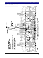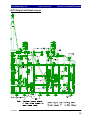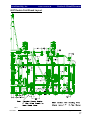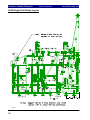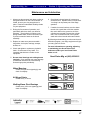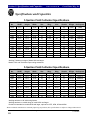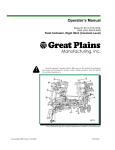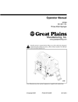
1
Operator’s Manual
Series VII 6330, 6332, 6538, 6539, 6541, 6544, 6546 & 6548
Field Cultivator, Floating Hitch
!
Read the operator’s manual entirely. When you see this symbol, the subsequent
instructions and warnings are serious - follow without exception. Your life and the
lives of others depend on it.
00399
Cover illustration may show optional equipment not supplied with standard unit.
©Copyright 2003 Printed 11/17/2008
560-205M
Great Plains Mfg., Inc.
First Page ►
Table of Contents
Table of Contents
Important Safety Information .......................... 1
Safety Rules................................................... 6
Safety Decals ................................................ 7
Introduction ........................................................ 12
Description of Unit ........................................ 12
Using this Manual ........................................ 12
Definitions.............................................. 12
Owner Assistance .......................................... 12
Assembly and Setup Assistance .................... 13
Product Support ..................................... 13
Pre-Assembly Checklist ........................ 13
Section 1 Assembly ............................................. 14
Center Torque Tube & Walking Beam
Assembly ................................................. 14
Inside Wing and Wheel Arm Assembly ....... 15
Brace Bar, Wing Brace & Rocker/Fold
Bracket Assembly .................................... 16
Center Level Bar Assembly ......................... 17
Center Caster Wheel Linkage &
Hitch Pole Assembly ............................... 18
Outside Wing Assembly ............................... 19
Connecting Outside Wing and Wing Brace
Assembly ................................................. 20
Wing Caster Wheel Linkage Assembly ....... 21
Center Lift Cylinder, Rest Pads and
Hydraulic Valves Assembly .................... 22
Fold Cylinders, Rocker Arm and 3” Rollers
Assembly ................................................. 23
Center Wing Stop and Outside Wing Stop
Assembly ................................................. 24
Gauge Wheel Assembly ............................... 25
Completing Setup ......................................... 26
Section 2 Hydraulics .......................................... 28
3-Section Lift Hose Layout .......................... 28
3-Section Fold Hose Layout ......................... 29
5-Section Lift Hose Layout .......................... 30
5-Section Fold Hose Layout ......................... 31
Section 3 Shank Placement ............................... 32
6330 Shank Layout ....................................... 32
6332 Shank Layout ...................................... 33
6537 Single Fold Shank Layout ................... 34
6537 Double Fold Shank Layout ................. 36
6539 Single Fold Shank Layout ................... 38
6539 Double Fold Shank Layout ................. 40
6541 Single Fold Shank Layout ................... 42
6541 Double Fold Shank Layout ................. 44
6544 Single Fold Shank Layout ................... 46
6544 Double Fold Shank Layout ................. 48
6546 Shank Layout ...................................... 50
6548 Shank Layout ...................................... 52
Section 4 Operating and Maintenance ............. 54
Prior To Going To The Field ....................... 54
General Operating Instructions and
In-Field Adjustments ............................... 55
Maintenance and Lubrication ....................... 57
Section 5 Specification and Capacities ............. 58
Appendix ............................................................. 59
Torque Values for Common Bolt Sizes ....... 59
Tire Inflation Chart ...................................... 59
Warranty ....................................................... 60
© Copyright 2003 All rights Reserved
Great Plains Manufacturing, Inc. provides this publication “as is” without warranty of any kind, either expressed or implied. While every precaution has been taken in the
preparation of this manual, Great Plains Manufacturing, Inc. assumes no responsibility for errors or omissions. Neither is any liability assumed for damages resulting from the
use of the information contained herein. Great Plains Manufacturing, Inc. reserves the right to revise and improve its products as it sees fit. This publication describes the state
of this product at the time of its publication, and may not reflect the product in the future.
Great Plains Manufacturing, Incorporated Trademarks
The following are trademarks of Great Plains Mfg., Inc.: Application Systems, Ausherman, Land Pride, Great Plains
All other brands and product names are trademarks or registered trademarks of their respective holders.
Printed in the United States of America.
11/17/2008
Series VII 6330-6548 Field Cultivator, Floating Hitch 560-205M
Important Safety Information
Great Plains Mfg., Inc.
Important Safety Information
Look for Safety Symbol
The SAFETY ALERT SYMBOL indicates there is
a potential hazard to personal safety involved
and extra safety precaution must be taken.
When you see this symbol, be alert and carefully
read the message that follows it. In addition to
design and configuration of equipment, hazard
control and accident prevention are dependent
upon the awareness, concern, prudence and
proper training of personnel involved in the
operation, transport, maintenance and storage of
equipment.
!
Be Aware of Signal Words
Signal words designate a degree or level of hazard seriousness.
DANGER indicates an imminently hazardous situation which, if not avoided, will result in death
or serious injury. This signal word is limited to
the most extreme situations, typically for
machine components that, for functional
purposes, cannot be guarded.
WARNING indicates a potentially hazardous
situation which, if not avoided, could result in
death or serious injury, and includes hazards
that are exposed when guards are removed. It
may also be used to alert against unsafe
practices.
CAUTION indicates a potentially hazardous situation which, if not avoided, may result in minor
or moderate injury. It may also be used to alert
against unsafe practices.
12/03/2003
! DANGER
! WARNING
! CAUTION
Series VII 6330-6548 Field Cultivator, Floating Hitch 560-205M
1
Important Safety Information
Great Plains Mfg., Inc.
Be Familiar with Safety Decals
•
Read and understand “Safety Decals,” page
7, thoroughly.
•
Read all instructions noted on the decals.
Keep Riders Off Machinery
•
Riders obstruct the operator’s view. Riders
could be struck by foreign objects or thrown
from the machine.
•
Never allow children to operate equipment.
•
Keep all bystanders away from machine during operation.
Shutdown and Storage
•
Lower Series VII Field Cultivator, put tractor
in park, turn off engine, and remove the key.
•
Secure Series VII Field Cultivator using
blocks and supports provided.
•
Detach and store Series VII Field Cultivator
in an area where children normally do not
play.
OFF
Use Safety Lights and Devices
•
Slow-moving tractors and towed implements
can create a hazard when driven on public
roads. They are difficult to see, especially at
night.
•
Use flashing warning lights and turn signals
whenever driving on public roads.
•
Use lights and devices provided with implement.
Series VII 6330-6548 Field Cultivator, Floating Hitch 560-205M
2
12/03/2003
Great Plains Mfg., Inc.
Important Safety Information
Transport Machinery Safely
Maximum transport speed for implement is 20
mph. Some rough terrains require a slower
speed. Sudden braking can cause a towed load
to swerve and upset.
•
Do not exceed 20 mph. Never travel at a
speed which does not allow adequate
control of steering and stopping. Reduce
speed if towed load is not equipped with
brakes.
•
Comply with state and local laws.
•
Do not tow an implement that, when fully
loaded, weighs more than 1.5 times the
weight of towing vehicle.
•
Carry reflectors or flags to mark tractor and
implement in case of breakdown on the
road.
•
Keep clear of overhead power lines and
other obstructions when transporting. Refer
to transport dimensions under
“Specifications and Capacities,” page 58.
•
Do not fold or unfold the wings while the
tractor is moving.
Avoid High Pressure Fluids
Escaping fluid under pressure can penetrate the
skin, causing serious injury.
•
Avoid the hazard by relieving pressure
before disconnecting hydraulic lines.
•
Use a piece of paper or cardboard, NOT
BODY PARTS, to check for suspected
leaks.
•
Wear protective gloves and safety glasses
or goggles when working with hydraulic
systems.
•
If an accident occurs, see a doctor immediately. Any fluid injected into the skin must be
surgically removed within a few hours or
gangrene may result.
12/03/2003
1/25/2005
Series VII 6330-6548 Field Cultivator, Floating Hitch 560-205M
3
Important Safety Information
Great Plains Mfg., Inc.
Practice Safe Maintenance
•
Understand procedure before doing work.
Use proper tools and equipment. Refer to
this manual for additional information.
•
Work in a clean, dry area.
•
Lower the Series VII Field Cultivator, put
tractor in park, turn off engine, and remove
key before performing maintenance.
•
Make sure all moving parts have stopped
and all system pressure is relieved.
•
Inspect all parts. Make sure parts are in
good condition and installed properly.
•
Remove buildup of grease, oil or debris.
•
Remove all tools and unused parts from
Series VII Field Cultivator before operation.
Prepare for Emergencies
•
Be prepared if a fire starts.
•
Keep a first aid kit and fire extinguisher
handy.
•
Keep emergency numbers for doctor, ambulance, hospital and fire department near
phone.
911
Wear Protective Equipment
•
Wear protective clothing and equipment.
•
Wear clothing and equipment appropriate for
the job. Avoid loose-fitting clothing.
•
Because prolonged exposure to loud noise
can cause hearing impairment or hearing
loss, wear suitable hearing protection such
as earmuffs or earplugs.
•
Because operating equipment safely
requires your full attention, avoid wearing
radio headphones while operating
machinery.
Series VII 6330-6548 Field Cultivator, Floating Hitch 560-205M
4
12/03/2003
Important Safety Information
Great Plains Mfg., Inc.
Handle Chemicals Properly
•
Agricultural chemicals can be dangerous.
Improper use can seriously injure persons,
animals, plants, soil and property.
•
Read and follow chemical manufacturer’s
instructions.
•
Wear protective clothing.
•
Handle all chemicals with care.
•
Avoid inhaling smoke from any type of
chemical fire.
•
Store or dispose of unused chemicals as
specified by chemical manufacturer.
Use A Safety Chain
•
Use a safety chain to help control drawn
machinery should it separate from tractor
drawbar.
•
Use a chain with a strength rating equal to or
greater than the gross weight of towed
machinery.
•
Attach chain to tractor drawbar support or
other specified anchor location. Allow only
enough slack in chain to permit turning.
•
Replace chain if any links or end fittings are
broken, stretched or damaged.
•
Do not use safety chain for towing.
Tire Safety
•
Tire changing can be dangerous and should
be performed by trained personnel using
correct tools and equipment.
•
When inflating tires, use a clip-on chuck and
extension hose long enough to you to stand
to one side–not in front of or over tire
assembly. Use a safety cage if available.
•
When removing and installing wheels, use
wheel-handling equipment adequate for
weight involved.
12/03/2003
Series VII 6330-6548 Field Cultivator, Floating Hitch 560-205M
5
Important Safety Information
Great Plains Mfg., Inc.
Safety Rules
•
Thoroughly read and understand the
instructions in this manual before operation.
Read all instructions noted on the safety
decals.
•
Be familiar with all Series VII Field Cultivator
functions.
•
Operate machinery from the driver’s seat
only.
•
Do not leave Series VII Field Cultivator unattended with tractor engine running.
•
Do not transport the field cultivator until
the transport position and transport pins
and all wing locks are installed.
•
Limit transport speed to 20 m.p.h.
•
Know the transport height of your unit and be
extremely careful of overhead electrical and
telephone lines when transporting the unit.
•
Know the transport width of your machine and
the width of bridges, etc… on the transport
route.
•
Never allow anyone to walk between the
tractor and field cultivator while machine is in
operation.
•
Make sure that no one is near the machine
during field operation and folding or unfolding
of wing sections.
•
Keep hands and feet away from cultivator
sweeps. They are quite sharp.
•
•
Prior to removing any lift cylinders from the
machine, lower implement to the ground, shut
off the tractor and release the pressure in the
lines.
Any moving piece of equipment is potentially
dangerous. Do not operate until you are
absolutely sure the area is clear of children,
pets and irresponsible persons.
•
•
Do not depend on cylinders to hold the weight
of machine during storage; use the transport
locks.
•
Do not walk or stand on any part of the
machine. Never allow anyone to ride on the
field cultivator.
Escaping hydraulic fluid under pressure can
have sufficient force to penetrate the skin,
causing serious injury. To prevent injury
when working with hydraulics, follow the
instructions on page 3.
•
Before transporting the unit on public roads,
check to make sure the safety reflectors are
clean and visible, and not missing or
damaged. Turn on tractor warning lights
when transporting.
•
Make sure all safety signs are clean, readable
and not damaged. Contact Great Plains Mfg.
for free replacements if necessary.
Series VII 6330-6548 Field Cultivator, Floating Hitch 560-205M
12/03/2003
•
•
6
Use extreme care when hitching or unhitching
the machine from the tractor. In some
situations with a heavy finishing attachment,
the machine may tip backward causing the
hitch to rise rapidly.
Never stand with feet under any part of the
machine.
Great Plains Mfg., Inc.
Table of Contents ►
Important Safety Information
Safety Decals
Your implement comes equipped with all safety
decals in place. They were designed to help you
safely operate your implement.
• Read and follow decal directions.
• Keep all safety decals clean and legible.
• Replace all damaged or missing decals. Order
new decals from your Great Plains dealer.
Refer to this section for proper placement.
•
•
When ordering new parts or components, also
request corresponding safety decals.
To install new decals:
1. Clean the area on which the decal is to be
placed.
2. Peel backing from decal. Press firmly on
surface, being careful not to cause air
bubbles under decal.
Slow Moving Vehicle Emblem
Quantity 1
Reflector – Amber (yellow)
838-615C
Quantity 6: Two on light brackets and two on
center brace bars. Two on rear of finishing
attachment (not shown), visible from side
while folded for transport.
1/25/2005
Series VII 6330-6548 Field Cultivator, Floating Hitch 560-205M
7
Important Safety Information
Table of Contents ►
Great Plains Mfg., Inc.
Reflector – Red
838-614C
Quantity 2
Reflector – Florescent Orange
838-603C
Quantity 2
Caution
838-598C
Quantity 1
Series VII 6330-6548 Field Cultivator, Floating Hitch 560-205M
8
1/25/2005
Great Plains Mfg., Inc.
Table of Contents ►
Important Safety Information
Danger Electrocution Hazard
838-599C
Quantity 1
Danger Crushing Hazard
838-600C
Quantity 1
Warning Overhead Wing Hazard
838-602C
Quantity 4 (3-section), 6 (5-section)
1/25/2005
Series VII 6330-6548 Field Cultivator, Floating Hitch 560-205M
9
Important Safety Information
Table of Contents ►
Great Plains Mfg., Inc.
Warning High Pressure Fluid Hazard
838-094C
Quantity 1
Warning Crushing Hazard
838-611C
Quantity 1
Series VII 6330-6548 Field Cultivator, Floating Hitch 560-205M
10
1/25/2005
11/17/2008
Great Plains Mfg., Inc.
Table of Contents ►
Important Safety Information
Warning Wing Falling Hazard
838-612C
Quantity 2
Notice
838-613C
Quantity 1
1/25/2005
Series VII 6330-6548 Field Cultivator, Floating Hitch 560-205M
11
Introduction
Table of Contents ►
Great Plains Mfg., Inc.
Introduction
Great Plains welcomes you to its growing family of
new product owners. This implement has been
designed with care and built by skilled workers
using quality materials. Proper assembly,
maintenance and safe operation will help you get
years of satisfactory machine use from your
machine. To ease the assembly task and produce
a properly working machine, read this entire
manual before assembling or setting up new
equipment.
personnel, parts and service equipment specially
designed for Great Plains products.
Your machine’s parts should only be replaced with
Great Plains parts. Always use the serial and
model number when ordering parts from your
Great Plains dealer. The serial-number and
patent plate (if provided) are located on the center
section of the implement on the front frame tube
as shown in Figure A.
Description of Unit
The Series VII 6330, 6332, 6537, 6541, 6544,
6546 & 6548 Field Cultivator is a 3 or 5-section
seedbed preparation tillage tool. Working width is
30 to 48 feet. The implement is designed for
secondary field operations to smooth, level,
eliminate weeds and incorporate chemicals.
Various finishing attachments are available to
further smooth, redistribute residue, firm soil and
break clods.
Using This Manual
This manual will familiarize you with safety,
assembly, operation, adjustment, troubleshooting
and maintenance. Read this manual and follow
the recommendations to help ensure safe and
efficient operation.
The information in this manual is current at printing. Some parts may change to assure top
performance.
Definitions
The following terms are used throughout this
manual.
Right and left as used in this manual are determined by facing the direction the machine will
travel while in use unless otherwise stated.
IMPORTANT: A crucial point of information about
the preceding topic. For safe and correct operation,
read and follow the directions provided before
continuing.
Figure A
Serial Number & Patent Plate
Record your implement model and serial numbers
here for quick reference.
Model Number: __________________________
Serial Number: ___________________________
Your Great Plains dealer wants you to be satisfied
with your new machine. If you do not understand
any part of this manual or are not satisfied with
the service received, please take the following
actions:
1. Discuss the matter with your dealer’s service
manager. Make sure they are aware of any
problems so they can assist you.
2. If you are still not satisfied, seek out the
dealership owner or general manager.
3. For further assistance, write to:
NOTE: Useful information about the preceding
topic.
Owner Assistance
If customer service or repairs are needed, contact
your Great Plains dealer. They have trained
Product Support
Great Plains Mfg. Inc.Service Department
PO Box 5060
Salina, KS 67402-5060
[email protected]
(800)-255-9215
Series VII 6330-6548 Field Cultivator, Floating Hitch 560-203M
12
11/17/2008
Great Plains Mfg., Inc.
Table of Contents ►
Introduction
Assembly and Setup Assistance
To order additional copies of operator’s and parts
manuals, write to the following address. Include
model numbers in all correspondence.
If you do not understand any part of this manual
or have other assembly or setup questions, assistance is available. Contact
Product Support
Great Plains Mfg. Inc., Service Department
607 Main Street
Tipton, KS 67485
Pre-Assembly Checklist
•
Before assembling, read and understand “Important Safety Information,” beginning on
page 1.
•
Have at least two people on hand while assembling.
•
Make sure assembly area is level and free of
obstructions (preferably an open concrete area).
•
Have all major components.
•
Have all fasteners and pins shipped with
Series VII Field Cultivator.
•
IMPORTANT: If a pre-assembled part or fastener is temporarily removed, remember
where it goes. Keep the parts separated.
•
Have a copy of the parts manual on hand. If
unsure of proper placement or use of any part
or fastener, refer to the parts manual.
•
Check that all working parts are moving freely, bolts are tight, and cotter pins are spread.
5/10/2007
Series VII 6330-6548 Field Cultivator, Floating Hitch 560-205M
13
Section 1: Assembly
Table of Contents ►
Great Plains Mfg., Inc.
Assembly
This section covers the proper assembly of the implement. The reference numbers on the
figures give you an indication of the order of assembly. For a complete breakdown of any part not
shown in this assembly section, refer to the parts manual for proper location. Refer to the Appendix
for proper bolt torque values.
Center Torque Tube & Walking Beam Assembly
After uncrating the machine, place the
center frame (1) Figure 1, in the center of your
work area on stands. Pin the torque tube (2) to
the center frame with the 1¼ x 6 pins (3) and 1
1/4 x 7 pin (4), secure them with 3/8 x 2 1/4
Gr.8 hex bolts (5) & top lock nuts.
Slide the pivot spindle of the walking
beam assembly (6) into the sleeve at the end of
the torque tube wheel arm. Take note of the
Left and Right Walking Beam Assembly (6).
The Flip Over Stop goes Toward Rear and
Grease Zerk up. It is a good idea to put some
form of anti-seize on the spindle before you
insert it. Line up the hole in the spindle with
the hole in the sleeve and secure with 5/16 x 4
1/2 hex bolt (7) with lock washer and hex nut.
When both walking beams have been
installed, bolt on the 9.5Lx15, 12 ply tires (8)
for 6330 & 6332 models or the 11L x 15, 12ply tires (8) for 6537-6548 models, using 1/2”
lug nuts (9). Bolt the 5x4 K-Flex stubs (10) on
with 1/2 x 6 1/2 hex bolts (11), lock washers
and hex nuts.
Figure 1
Series VII 6330-6548 Field Cultivator, Floating Hitch 560-205M
14
11/22/2005
Great Plains Mfg., Inc.
Table of Contents ►
Section 1: Assembly
Inside Wing and Wheel Arm Assembly
Bolt the inside wing frames (1) Figure
2, to the center frame with two 1 x 6 hex bolts
(2) with nylon lock nuts (3). Draw the nuts
down tight but do not torque.
Once the wings are attached, insert the
wheel arm bracket (4) into the wing frame
hangers and secure it just as you did on the
center with 1 1/4 x 6 pins (5). Secure the pins
with 3/8 x 2 1/4 Gr.8 hex bolts (6) & top lock
nuts.
Install the wing walking beam assembly
(7) as shown in Figure 2 with the 14” spindle
(6330 & 6332) or 18” spindle (6537-6548)
toward the front and 13” spindle on the back..
Secure the pivot spindle in the sleeve with the
5/16 x 3 clevis pin (8) and 1/8 x 1 cotter. Use
anti-seize material on spindles
Bolt the 9.5L x 15, 8-ply tire (9) in
place with the 1/2 x 1 1/4 lug bolts (10). On
model 6332, bolt the 11” bolt on stub (12) to
the wing frame using 5/8 x 1 1/2 hex bolts (13),
using lock washers and hex nuts.
Figure 2
1/22/2005
Series VII 6330-6548 Field Cultivator, Floating Hitch 560-205M
15
Section 1: Assembly
Table of Contents ►
Great Plains Mfg., Inc.
Brace Bar, Wing Brace & Rocker/Fold Bracket Assembly
Install the 1 x 7 1/2 eye bolt (1) Figure
3, in the mounting bracket at the back of the
wing with a 1” jam nut on each side of the
bracket. Install the 3 1/4 x 8 rephasing wing
cylinder (2) between the eyebolt and the lever
on the wheel bracket. Secure the cylinder with
1 x 3 clevis pins, 1” machine washer and 3/16 x
2 cotter pin.
Bolt the center brace bar (3) and wing
brace bar (5) to the front of the center frame
and wing frame with 3/4 x 2 hex bolts (4) with
lock washers and hex nuts. Do not tighten
bolts. Use a 1 x 6 hex bolt (6) and nylon lock
nut in the hinge. Draw nut tight but do not
torque. Insert the cylinder mounting tube (7)
between the center frame and the brace bar.
Attach with 5/8 x 4 x 4 1/2 u-bolts (11) and 3/4
x 2 hex bolts (12), lock washers and nuts. Insert
the leveling link tubes (8 thru 10) and attach
with u-bolts (11) as before. Tightening all u-
bolts and brace bar bolts evenly to prevent
binding at hinge.
Bolt the rocker/fold brackets (13) &
(14), if applicable, to the wing using two 3/4 x
2 1/2 hex bolts (15) with lock washers and hex
nuts, along with two 5/8 x 3 x 5 1/2 u-bolts (16)
with lock washer and hex nuts. The front
bracket uses a 3/4 x 5 bolt (17) to attach the
outer end. The rear bracket uses four 5/8 x 2
bolts (18) with lock washers and hex nuts to
attach the outer end. Bolt the inside hinge (19)
to the wing brace using 5/8 x 2 bolts (20) and
one 5/8 x 3 x 5 1/2 u-bolt (21) with lock
washers and hex nuts. Bolt the 5” stub (22) to
the wing frame using 5/8 x 1 1/2 bolts (23) with
lock washers and hex nuts.
Model 6330 & 6332 has rocker bracket
(24), connecting link (25) and connecting link
bracket (26). Assemble with 1 x 3 hex bolts
(27) with 1” lock nuts, 1/2 x 3 x 5 u-bolts (28)
with lock washers and hex nuts.
Figure 3
Series VII 6330-6548 Field Cultivator, Floating Hitch 560-205M
16
11/22/2005
Great Plains Mfg., Inc.
Table of Contents ►
Section 1: Assembly
Center Level Bar Assembly
Slide the H-bracket (1) down over the
cylinder mount tube as shown in Figure 4. Bolt
in place with a 3/4 x 8 bolt (2) and lock nut.
Draw this nut up but do not torque, as this part
must pivot.
Connect the level bars (3) and (4) to the
torque tube using two 1 x 3 3/8 usable clevis
pins (5), 1” flat washers, 1” machine washers
and 3/16 x 2 cotter pins. Install the 1 1/4 x 13
1/2 Gr.8 bolt (6) through the level bars and Hbracket. Draw up snug with a 1 1/4 top lock
nut do not torque.
Connect the three level bar cross braces
(7) between the level bars and bolt in place
with 5/8 x 1 1/2 bolts (8) using nuts and lock
washers. Slide the leveling links (9) over the
leveling link mounting tubes as shown. Bolt in
place with 1 x 6 special thread Gr.8 hex bolts
(10), securing with nylon lock nuts. Do not
torque, as this part must pivot freely. Connect
the gauge wheel level bars (11) to the level bars
(3 & 4) using two 1 x 4 1/2 headed pins (12),
1” machine washers and 3/16 x 2 cotter pins.
Bolt the gauge wheel level bar (11) to
the turnbuckle assembly (13) through the
leveling link (9) as shown. Use the 1 x 6
special thread hex bolt and nylon lock nut. Do
not torque as before.
Attach the rebound valve mounting
bracket (14) and valve mounting bracket plate
(15) with four 1/2 x 4 1/2 bolts (16) using lock
washers and hex nuts. Insert the 3/4 x 3
transport pin (17) in holder.
Figure 4
1/22/2005
Series VII 6330-6548 Field Cultivator, Floating Hitch 560-205M
17
Section 1: Assembly
Table of Contents ►
Great Plains Mfg., Inc.
Center Caster Wheel Linkage & Hitch Pole Assembly
Bolt the center fold bars (1) to the
center frame as shown in Figure 5. Use 3/4 x 2
1/2 hex bolts (2) with lock washers & hex nuts.
Bolt the center frame truss (3) to the center
frame using 5/8 x 1 1/2 hex bolts (4), lock
washers and hex nuts, and 3/4 x 2 hex bolts (5)
with lock washers and hex nuts.
U-bolt the gauge wheel arm mount (6)
to the center brace bar with three 3/4 x 3 x 5 1/2
u-bolts (7). Insert the left & right bottom center
gauge wheel arms (8 & 9) and secure with 1 x 5
1/2 special hex bolts (11) and nylon lock nuts,
do not torque.
Attach the top gauge wheel arms (10) with the
same 1 x 5 1/2 special hex bolt and nylon lock
nut, do not torque. Connect the turnbuckle to
the bottom arms with a 1 x 4 clevis pin (12),
machine washer and 3/16 x 2 cotter pin. See
Caster Wheel Assembly, Section 3
Replacement Parts, for caster wheel exploded
diagram.
Bolt the hitch pole (13) to the brace bar
with two 1 1/4 x 7 1/2 Gr. 8 hex bolts (14),
secure with 1 1/4 lock nuts but do not torque.
Insert the tongue jack (15) on the hitch pole
jack tube. Bolt the hitch clevis (16) to the hitch
pole with 1 1/2 x 11 safety chain bolt (17),
machine washers, slotted hex nut and 1/4 x 3
cotter pin. Attach hose holder (18) with 1/8 x 1
1/2 cotter pin.
Figure 5
Series VII 6330-6548 Field Cultivator, Floating Hitch 560-205M
18
11/22/2005
Great Plains Mfg., Inc.
Table of Contents ►
Section 1: Assembly
Outside Wing Assembly
On 5-section models, assemble the
outside wing (1) by attaching the outside hinges
(2) to the wing with 1 x 6 hex bolt (3) and 5/8 x
3 x 5 1/2 u-bolts (4) as shown in Figure 6. Use
a nylon lock nut on the 1 x 6 hex bolt (3) with
lock washers and hex nuts on the u-bolt.
Attach the 180 degree rocker (5), bulge side
out, with the 1 x 3 headed pin (6), 1” machine
washer and 3/16 x 2 cotter pin.
Attach the outside wheel bracket (7) just
as we did the inside ones, using the 11/4 x 6
pins (8) and 3/8 x 2 1/4 Gr.8 hex bolts & top
lock nuts. Slide the walking beam assembly (9)
into the wheel bracket sleeve as shown in
Figure 6. Again, it is recommended to use
some form of anti-seize product on the spindle.
Secure with 5/16 x 3 clevis pin (10) and 5/32 x
1 1/2 cotter pin. Note that the longer 14” long
spindle assembly goes to the front. Bolt on the
9.5L x 15 tire and wheels (11) with the 1/2 x 1
1/4 lug bolts (12).
Model 6537 & 6539 use one tire and a
14” Hub & Spindle assembly (13) as shown in
insert.
Figure 6
1/22/2005
Series VII 6330-6548 Field Cultivator, Floating Hitch 560-205M
19
Section 1: Assembly
Table of Contents ►
Great Plains Mfg., Inc.
Connecting Outside Wing and Wing Brace Assembly
On 5-section models, bolt the outside
wing assembly (1) to the inside wing frame
with Gr.8, 1 x 6 hex bolts, 1 3/4 thread (2)
Figure 7, securing with 1” nylon lock nuts.
Bolt the outside wing brace (3) to the
plate on the outside wing with 5/8 x 1 1/2 bolts
(4), with lock washers and hex nuts. Bolt the
outside hinge (5) to the wing brace using two
5/8 x 3 x 5 1/2 u-bolts (6), with lock washers
and hex nuts, and a 1 x 5 1/2 hex bolt (7) with
nylon lock nut.
Bolt the 25” offset stub (8) as shown for
your model, with 5/8 x 4 x 4 1/4 u-bolts (9)
lock washers and hex nuts. Also attach the
bolt-on C-frame (10) with 5/8 x 1 1/2 hex bolts
(11), lock washers and hex nuts.
Attach the 3 x 8 DR hydraulic cylinder
(12) between the lever on the wheel bracket and
the 1 x 7 1/2 eye bolt (13) mounted in the
bracket in the back of the wing. Use 1 x 3 1/2
clevis pins (14) with 1” machine washer and
3/16 x 2 cotter pins and 1” jam nuts on the eyebolt.
Attach the 5” bolt on stub (15) to the
outside of the wing frame using 5/8 x 1 1/2 hex
bolts (16), using lock washers and hex nuts.
On 6544 & 6546 models, u-bolt the 11” u-bolt
on stub (17) as shown, using 5/8 x 4 x 4 1/4 ubolts (9). On 6537, 6539, 6541, 6544 models,
attach the 4x4 K-Flex stub (18) as shown with
1/2 x 5 1/2 hex bolts (19). On 6541 model,
attach the 4 1/2” u-bolt on stub (20) as shown
with 5/8 x 4 x 4 1/4 u-bolts (9) using lock
washers and hex nuts.
Figure 7
Series VII 6330-6548 Field Cultivator, Floating Hitch 560-205M
20
11/22/2005
Great Plains Mfg., Inc.
Table of Contents ►
Section 1: Assembly
Wing Caster Wheel Linkage Assembly
Insert the wing level bar (1) through
the hole in the rocker fold bracket as shown in
Figure 8. Attach the wing level bar (1) to the
wheel bracket with a 1 x 3 3/8 usable clevis
pin (2), 1” flat washers, 1” machine washer
and 3/16 x 2 cotter pin. Slide the leveling link
(3) over the leveling link mounting tube and
attach with a 1 x 6 special thread GR 8 hex
bolt (4) and nylon lock nut, do not torque.
Bolt the gauge wheel level bar (1) to the
turnbuckle assembly (5) through the leveling
link (3) as shown. Use a 1 x 6 Gr.8 special
thread hex bolt (4) and nylon lock nut. Do not
torgue as before.
U-bolt the gauge wheel arm mounts (6
& 7) to the brace bar with three 3/4 x 3 x 5 1/2
u-bolts (8), lock washers and hex nuts. Insert
the bottom gauge wheel arm (10) and secure
with 1 x 5 1/2 special hex bolts (9) and nylon
lock nuts, do not torque. Attach the top gauge
wheel arm (11) with the same 1 x 5 1/2 special
hex bolt and nylon lock nut, do not torque.
Connect the turnbuckle to the bottom arm with
a 1 x 4 clevis pin (12), machine washer and
3/16 x 2 cotter pin. See Caster Wheel
Assembly, Section 3, in parts manual, for
caster wheel exploded diagram.
Figure 8
1/22/2005
Series VII 6330-6548 Field Cultivator, Floating Hitch 560-205M
21
Section 1: Assembly
Table of Contents ►
Great Plains Mfg., Inc.
Center Lift Cylinder, Rest Pads and Hydraulic Valves Assembly
Connect the two 3 1/2 x 8 main lift
cylinders (1) to the center frame as in Figure 9.
Connect the rod ends to the lugs on the Hbracket. Place a 1” flat washer on each side of
the lug on the H-bracket to keep the hardened
bushings from coming out.
Secure the cylinders with 1 x 3 1/2”
clevis pins (2), 1” machine washers and 3/16 x
2 cotter pins. Mount the rebound valve (3) as
shown with the V1 port to the front and top
using two 5/16 x 4 hex bolts (4) with lock
washers and hex nuts.
Install the depth stop mounting bracket
(5) to the center brace bar using two 5/8 x 3 x
5 1/2 u-bolts (6), lock washers and hex nuts.
Bolt the depth stop valve (7) on top of the
bracket using the 5/16 x 2 hex bolts (8) with
lock washers. Insert the depth stop tube (9)
into the mounting bracket (5) and attach to the
level bar with 1/2 flat washer and 1/8 x 1
cotter pin. Bolt the depth stop assembly (10)
to the depth stop tube (9) with two 1/2 x 2 1/2
hex bolts (11) using 1/2” lock washers and hex
nuts.
U-bolt the 3 1/2” cylinder rest pads
(12) on the back bar, if applicable, using a 1/2
x 3 x 5 u-bolt (13) with lock washers and hex
nuts. U-bolt the 3” or 4” cylinder rest pads
(14) on the center frame as shown, using a 1/2
x 3 x 5 u-bolt (13) with lock washers and hex
nuts (see shank layout drawing for exact
placement).
Figure 9
Series VII 6330-6548 Field Cultivator, Floating Hitch 560-205M
22
11/22/2005
Great Plains Mfg., Inc.
Table of Contents ►
Section 1: Assembly
Fold Cylinders, Rocker Arm and 3” Rollers Assembly
Connect the center fold 4 x 24
cylinders (1) to the center fold bracket as
shown in Figure 10. Use the 1” x 3 1/2 clevis
pin (2) with 1” machine washer and 3/16 x 2
cotter pin. Attach the 5¾” (3-section) or 6
1/2” rocker (5-section) (3) to rocker bracket
with 1 x 3 Headed Pin (4) using 1” machine
washer and 3/16 x 2 cotter. Do Not Connect
Rod End Of Cylinders To Rockers Before
They Are Charged With Oil.
Figure 11
Once the fold cylinders are fully
charged and free of air, connect them to the
rockers. Use a 1 x 5 1/2 bolt (8) to bolt two 3”
rollers (9), one on each side, to the 180 degree
rocker as shown in Figure 11. Secure with 1”
nylon lock nut. Rollers must turn freely!
Figure 10
On 5-section models, connect the base
of the 4 x 16 fold cylinders (7) to the
Rocker/Fold bracket with 1 x 3 1/2 clevis pin
(2), 1” machine washer and cotter (see Figure
10). Do Not Connect Rod End Of Cylinders
To Rockers. Bolt the hose holders (5) to the
center frame with a 1/2 x 4 1/2 hex bolt (6),
using a lock washer and hex nut.
Place a support block of wood under
the cylinders, as shown, so they clear the
rockers in the extended position. You are now
ready to connect the hydraulic hoses to the
cylinders and charge the fold system (see
hydraulic layout).
1/22/2005
Figure 12
On machines with rear fold cylinders
and Magnum Shanks, the hydraulic fittings
need to be rotated as shown in Figure 12 to
clear the Magnum shank upright when folded.
Series VII 6330-6548 Field Cultivator, Floating Hitch 560-205M
23
Section 1: Assembly
Table of Contents ►
Great Plains Mfg., Inc.
Center Wing Stop and Outside Wing Stop Assembly
U-bolt the center wing stop (1) to the
second bar from the rear on the center frame as
shown in Figure 13. Use 5/8 x 4 x 4 1/4 ubolts (2) with lock washers and hex nuts.
Center the wing stop from side to side. Insert
the 1/2 x 4 1/2 transport lock quick pins (3) in
the holders on the wing stop.
On Model 6541-6548, attach the center
wheel alignment stub (4) to the center of the
wing stop using 5/8 x 2 1/2 x 3 1/2 u-bolts (5),
lock washers and hex nuts. U-bolt the wing
wheel alignment stub (6) to the inside wing
frame using 1/2 x 3 x 5 u-bolts (7), lock
washers and hex nuts. See shank layout for
proper location for your model.
On Models 6537-6548, u-bolt the wing
lock mount (8) on the inside wing with 1/2 x 3
x 5 u-bolts (9). U-bolt the wing lock “T”
bracket (13) on the outside wing with the same
1/2 x 3 x 5 u-bolt (9). Refer to the shank layout
for your particular model for the exact location
of the wing lock mount and lock “T” bracket.
Use lock washers and hex nuts on these u-bolts
(Note: On models 6537 and 6541 the TBracket uses 5/8 x 4 1/32 x 4 1/4 u-bolts).
Bolt the wing latch (10) to the wing lock
mount (8) with a 3/4 x 4 1/2 bolt (11). Slide a
3/4 flat washer (12) between the latch and the
mount on each side to take out the slop. Use a
3/4” lock nut but do not torque down. The
latch must move freely.
Figure 13
Series VII 6330-6548 Field Cultivator, Floating Hitch 560-205M
24
11/22/2005
Great Plains Mfg., Inc.
Table of Contents ►
Section 1: Assembly
Gauge Wheel Assembly
U-bolt the gauge wheel bracket (1) to
the front bar of inside wing brace as shown in
Figure 14 using the 5/8 x 4 x 4 1/4 u-bolts (2),
lock washers and hex nuts. Slide the gauge
wheel arm/hub assembly (3) up into the gauge
wheel bracket (1) and pin with the 3/4 x 4 1/2
pin (4). Use four 1/2 x 1 hex bolts (5) to
secure the arm and make it rigid. Bolt on the
4-bolt rim and tire (6) with four 1/2 x 1 lug
bolts (7). For directions on the proper setting
for the gauge wheel during operation, refer to
section 4.
Figure 14
1/22/2005
Series VII 6330-6548 Field Cultivator, Floating Hitch 560-205M
25
Section 1: Assembly
Table of Contents ►
Great Plains Mfg., Inc.
Completing Setup
Install the plastic end caps into all the
open ends of all the 4x3 frame tubes.
You should now be ready to add
shanks to the machine and then if the machine
has a finishing attachment you would install it
following the shanks. See the shank layout
section 4 for proper shank locations for your
unit. Section 3 in this manual shows the
individual shank assemblies and parts for both
the K-flex and magnum shanks.
Once the shanks are installed and all of
the hydraulic procedures have been completed,
you may fold the machine to check for
clearance and proper shank placement. Slowly
fold the machine while watching that hoses do
not become pinched or kinked and watch that
shanks clear all obstructions.
Once the machine is folded completely,
begin to unfold slowly. Be Sure No One Is
Under The Wings When You Unfold The
Machine. Once the machine is unfolded, add
the safety decals and the product decals. Refer
to the Important Safety Information section
(page 7) for the proper placement of safety
decals. Product decal placement is shown in
section 4 along with the shank placement.
Install the safety chain, SMV sign &
safety lights in accordance with local and state
laws. See parts manual (Section 2: Frames)
for assembly drawings and parts list.
At this point, set up of the machine is
complete and you are ready to add any
finishing attachment, rear hitches, etc… to the
machine. Be sure to consult the operating
instructions, section 4, for the first time field
adjustments before going to the field for the
first time.
Series VII 6330-6548 Field Cultivator, Floating Hitch 560-205M
26
11/22/2005
Great Plains Mfg., Inc.
Table of Contents ►
Section 1: Assembly
This page intentionally left blank
1/22/2005
Series VII 6330-6548 Field Cultivator, Floating Hitch 560-205M
27
Section 2: Hydraulics
Table of Contents ►
Great Plains Mfg., Inc.
3-Section Lift Hose Layout
Series VII 6330-6548 Field Cultivator, Floating Hitch 560-205M
28
1/25/2005
Great Plains Mfg., Inc.
Table of Contents ►
Section 2: Hydraulics
3-Section Fold Hose Layout
1/25/2005
Series VII 6330-6548 Field Cultivator, Floating Hitch 560-205M
29
Section 2: Hydraulics
Table of Contents ►
Great Plains Mfg., Inc.
5-Section Lift Hose Layout
Series VII 6330-6548 Field Cultivator, Floating Hitch 560-205M
30
1/25/2005
Great Plains Mfg., Inc.
Table of Contents ►
Section 2: Hydraulics
5-Section Fold Hose Layout
1/25/2005
Series VII 6330-6548 Field Cultivator, Floating Hitch 560-205M
31
Section 4: Shank Placement
Table of Contents ►
Great Plains Mfg., Inc.
6330 Shank Layout
00409
Series VII 6330-6548 Field Cultivator, Floating Hitch 560-205M
32
4/7/2008
Great Plains Mfg., Inc.
Table of Contents ►
Section 4: Shank Placement
6332 Shank Layout
00410
4/7/2008
Series VII 6330-6548 Field Cultivator, Floating Hitch 560-205M
33
Section 4: Shank Placement
Table of Contents ►
Great Plains Mfg., Inc.
6537 Single Fold Shank Layout
00411
Series VII 6330-6548 Field Cultivator, Floating Hitch 560-205M
34
4/7/2008
Great Plains Mfg., Inc.
Table of Contents ►
Section 4: Shank Placement
6537 Single Fold Shank Layout
4/7/2008
5/23/2008
5/23/2008
Series VII 6330-6548 Field Cultivator, Floating Hitch 560-205M
35
Section 4: Shank Placement
Table of Contents ►
Great Plains Mfg., Inc.
6537 Double Fold Shank Layout
00413
Series VII 6330-6548 Field Cultivator, Floating Hitch 560-205M
36
4/7/2008
5/23/2008
Great Plains Mfg., Inc.
Table of Contents ►
Section 4: Shank Placement
6537 Double Fold Shank Layout
00414
4/7/2008
5/23/2008
Series VII 6330-6548 Field Cultivator, Floating Hitch 560-205M
37
Section 4: Shank Placement
Table of Contents ►
Great Plains Mfg., Inc.
6539 Single Fold Shank Layout
00415
Series VII 6330-6548 Field Cultivator, Floating Hitch 560-205M
38
4/7/2008
Great Plains Mfg., Inc.
Table of Contents ►
Section 4: Shank Placement
6539 Single Fold Shank Layout
00416
4/7/2008
Series VII 6330-6548 Field Cultivator, Floating Hitch 560-205M
39
Section 4: Shank Placement
Table of Contents ►
Great Plains Mfg., Inc.
6539 Double Fold Shank Layout
00417
Series VII 6330-6548 Field Cultivator, Floating Hitch 560-205M
40
4/7/2008
Great Plains Mfg., Inc.
Table of Contents ►
Section 4: Shank Placement
6539 Double Fold Shank Layout
00418
4/7/2008
Series VII 6330-6548 Field Cultivator, Floating Hitch 560-205M
41
Section 4: Shank Placement
Table of Contents ►
Great Plains Mfg., Inc.
6541 Single Fold Shank Layout
00419
Series VII 6330-6548 Field Cultivator, Floating Hitch 560-205M
42
4/7/2008
Great Plains Mfg., Inc.
Table of Contents ►
Section 4: Shank Placement
6541 Single Fold Shank Layout
00420
4/7/2008
Series VII 6330-6548 Field Cultivator, Floating Hitch 560-205M
43
Section 4: Shank Placement
Table of Contents ►
Great Plains Mfg., Inc.
6541 Double Fold Shank Layout
00421
Series VII 6330-6548 Field Cultivator, Floating Hitch 560-205M
44
4/7/2008
Great Plains Mfg., Inc.
Table of Contents ►
Section 4: Shank Placement
6541 Double Fold Shank Layout
00422
4/7/2008
Series VII 6330-6548 Field Cultivator, Floating Hitch 560-205M
45
Section 4: Shank Placement
Table of Contents ►
Great Plains Mfg., Inc.
6544 Single Fold Shank Layout
00423
Series VII 6330-6548 Field Cultivator, Floating Hitch 560-205M
46
4/7/2008
Great Plains Mfg., Inc.
Table of Contents ►
Section 4: Shank Placement
6544 Single Fold Shank Layout
00424
4/7/2008
Series VII 6330-6548 Field Cultivator, Floating Hitch 560-205M
47
Section 4: Shank Placement
Table of Contents ►
Great Plains Mfg., Inc.
6544 Double Fold Shank Layout
00425
Series VII 6330-6548 Field Cultivator, Floating Hitch 560-205M
48
4/7/2008
Great Plains Mfg., Inc.
Table of Contents ►
Section 4: Shank Placement
6544 Double Fold Shank Layout
00426
4/7/2008
Series VII 6330-6548 Field Cultivator, Floating Hitch 560-205M
49
Section 4: Shank Placement
Table of Contents ►
Great Plains Mfg., Inc.
6546 Shank Layout
00427
Series VII 6330-6548 Field Cultivator, Floating Hitch 560-205M
50
4/7/2008
Great Plains Mfg., Inc.
Table of Contents ►
Section 4: Shank Placement
6546 Shank Layout
00428
4/7/2008
Series VII 6330-6548 Field Cultivator, Floating Hitch 560-205M
51
Section 4: Shank Placement
Table of Contents ►
Great Plains Mfg., Inc.
6548 Shank Layout
00429
Series VII 6330-6548 Field Cultivator, Floating Hitch 560-205M
52
4/7/2008
Great Plains Mfg., Inc.
Table of Contents ►
Section 4: Shank Placement
6548 Shank Layout
00430
4/7/2008
Series VII 6330-6548 Field Cultivator, Floating Hitch 560-205M
53
Section 4: Operating and Maintenance
Table of Contents ►
Great Plains Mfg., Inc.
Operating and Maintenance
Prior to Going to the Field
1. Both dealer and customer read and
thoroughly understand all safety
recommendations. (These are found in the
Safety Section of this operator manual.)
2. Make sure your tractor horsepower matches
the implement you are pulling. This is
important so the implement can do the best
possible job.
8. Pre-leveling of machine can be done on a
concrete slab or good level surface. Lower
machine so sweeps are 1-2” off of ground on
the center frame. Adjust the turnbuckle
(Figure 1) at the front of machine to level it
from front to back. (Shorten to bring front
down, extend to bring front up.) Level
machine with the front row shanks just slightly
deeper or lower than the back.
3. Hitch the tractor to the Field Cultivator using
the block or yoke clevis determined by the
tractor drawbar. Use the correct size pin for
clevis or block. Raise any 3-pt arms and/or
hitch attachments to its fully raised
position to clear implement.
4. For TWO-WHEEL DRIVE and MFWD
tractors, pin drawbar in fixed center position
for field and transport. For FOUR-WHEEL
DRIVE and TRAC-DRIVE tractors, leave
one hole clearance on each side of
drawbar for field position, hitch damage
may occur if pinned solid. Pin in center
position for transport to maintain
maximum steering control.
5. Clean all hydraulic couplings and connect to
tractor. Each hydraulic coupling has a colored
handle on it and is marked with a cylinder,
either extending (black) or retracting (red).
Figure 1
9. Set the wings to match the depth of the
center. This is done by adjusting the lift
cylinder eyebolt on each wing (see Figure 2).
Lengthen the bolt to run shallower, shorten
the bolt to run deeper.
6. If machine is folded, remove the transport pins
from the wing stops. (Do not remove pins if
the wing is leaning against the pins or putting
pressure on the pins. Use the hydraulics to
pull the wings in completely before unpinning
them.) Once the pins are removed, slowly
unfold the unit. Make sure no one is under
the wings during the unfolding process.
Check again for hydraulic leaks and watch
that hoses do not get pinched in hinges, wings
stops, etc.
7. After the machine is completely unfolded,
raise and lower the Field Cultivator several
times to purge air from the hydraulic system.
Again check for hydraulic leaks and tighten or
replace if necessary.
Series VII 6330-6548 Field Cultivator, Floating Hitch 560-205M
54
Figure 2
In some conditions the wings will need to be
set slightly lower than the center as the center
may tend to run deeper behind the tractor
tires.
1/25/2005
Great Plains Mfg., Inc.
Table of Contents ►
10. Check safety chain hookup. Make sure all
warning lights are hooked up and functioning
correctly.
11. Check the tire pressure for proper inflation
and check the tightness of the lug bolts. Tire
pressure amounts are located on the sidewall
of each tire.
Section 4: Operating and Maintenance
12. Check for any bolts that may need tightened
or retightened. Grease all the hinge points.
The hubs come pre greased and will not need
more grease at this time.
13. Put transport lock in place and refold the
machine slowly. Put wing stop pins in place.
Always use the transport pins when moving
from field to field. You are now ready to go to
the field.
General Operation Instructions and In-Field Adjustments
1. Remove the transport pins and unfold the
machine. Make sure the fold cylinders are fully
extended to allow the wings to fully flex in the
field.
2. If possible have someone observe the machine
during first time operation for levelness—front
to rear and wings to center frame. Adjust each
as needed. For front to rear, either extend or
shorten the length of the turnbuckle on the selfleveling. Never run the machine with the back
lower (deeper) than the front. To adjust the
machine from side to side, use the eyebolt on
each wing. Adjust the inside wings first and
then the outside wings. The gauge wheels
should be set in field position to be ½” to 1 ½”
off the ground.
3. The ideal working speed is 6 to 7 mph.
Working too slow may cause plugging, poor
incorporation or mixing of crop residue and
reduced weed kill. Running too fast may
cause streaks in chemical incorporation and
ridging.
flow speed down. If this problem still persists,
contact the factory service representative for
other possible adjustments. Do not try to
adjust the rebound valve without first
contacting the factory service rep.
7. Adjust the drag to leave the desired results
while maintaining the trash flow through the
drag.
a.) On the spike drag, start with 5 links
hanging from the chain in drag arm bottom
slot. (This is the starting point for worst
conditions.) The cleaner the ground, the
shorter the pull chain may be pulled up.
On the spike drag, one of the links in the
first row of angles is turned over. This
allows the trash to start flowing through the
drag easier by changing the angle of the
4. The field cultivator is designed as a secondary
tillage tool and is designed to leave a finished
seedbed following some form of fall or spring
tillage. For best results, if at all possible, run
the machine at a slight angle to the rows. This
will improve trash flow and help spread the
residue more evenly throughout the field.
5. When you have the machine set to the desired
working depth, set the depth stop slide on the
depth control bar. This is located at the front of
the machine on the brace bar. This will
maintain a constant depth each time after
ASSEMBLE WITH LINK UP AS
raising and lowering the machine.
SHOWN.
IN
SOME
CONDITIONS
THE
FRONT
6. If after setting the depth stop, the detent on the LINK MAY BE ASSEMBLED
tractor kicks out before the stop contacts the DOWN TO HELP START
TRASH TO FLOW THROUGH
button on the depth stop, slow the hydraulic
THE HARROW.
1/25/2005
Series VII 6330-6548 Field Cultivator, Floating Hitch 560-205M
55
Section 4: Operating and Maintenance
Table of Contents ►
first row of teeth. Always make sure that
the drag is never pulling off the hang
chains. If so, shorten pull chains.
b.) On coil tine drags, start with the top
eyebolt (12) centered. Then level drag
mainframe (4R and 4L) by changing
position of leveling bolt (21). There are
two holes in the arm and four in the
mainframe. One of these will get you
where you need to be to level. To lay the
teeth back, remove the clip pin (42) on
each end and move strap adjustment by
pushing the handle (7) forward. This strap
has 5 holes and will let you lay the teeth
back several degrees. If it is desired to set
Series VII 6330-6548 Field Cultivator, Floating Hitch 560-205M
56
Great Plains Mfg., Inc.
one row, usually the first, different than the
rest as far as the angle is concerned, it can
be adjusted individually by loosening the
U-bolt and set- screw on each end of the
drag bar. Down pressure on the drag is
achieved by lengthening the eyebolt (12)
on the top bracket. Depending on the
amount of down pressure, you may need
to relevel the mainframe.
c.) If a basket is added, adjust the amount of
down pressure by either shortening the
eyebolt for less pressure or lengthening
the eyebolt for more pressure.
1/25/2005
Great Plains Mfg., Inc.
Table of Contents ►
Section 4: Operating and Maintenance
Maintenance and Lubrication
1. Always use the transport lock when working or
doing maintenance on the Field Cultivator. If
folded, be sure your wing stop pins are in
place. Read and understand all safety decals
on your equipment.
2. During the first season of operation, and
periodically after that, check your bolts for
tightness. Check shank pivot bolts on the
spring-loaded shank; these must remain tight
to prevent excessive wear on the shank
assembly.
6. Check drag bolts and parts for looseness or
excessive wear. Replace broken or bent teeth.
Your drag is an important part of the tillage
operation.
7. If machine is stored outdoors over the winter
months it is a good idea to fold the machine
then set it down on the ground so all of the
cylinders are retracted to protect the cylinder
rods. This will extend the life of the cylinder
seals and reduce internal and external leaks.
By following and maintaining a routine service and
lubrication program, your tillage equipment will give
you many years of service.
3. Replace or rotate worn parts as needed—
hinge bolts, clevis pins, bearings, sweeps,
shanks, etc...
For more information on operating, adjusting
or maintaining your Great Plains Field
Cultivator contact your local Great Plains
dealer or call
4. Check and tighten or replace any hydraulic
leaks. Check hoses for any leaks. It is
important that there are no leaks on the
equipment.
5. Grease wheel bearings and walking beams
sparingly. Over greasing may cause damage
to seals and reduce the life of the bearing.
Grease hinge points periodically.
Great Plains Mfg. at (800) 255-9215
Wheel Bearings
Grease every 50 hours (sparingly) and
check for endplay.
All Hinge Points
Grease every 10 hours.
Walking Beam Pivot Bearings
Grease every 100 hours (sparingly) and
check for endplay.
1/25/2005
Series VII 6330-6548 Field Cultivator, Floating Hitch 560-205M
57
Section 5: Specifications and Capacities
Table of Contents ►
Great Plains Mfg., Inc.
Specifications and Capacities
3-Section Field Cultivator Specifications
Model
No.
6113
6116
6318
6320
6323
6325
6328
6330
6332
7332
7334
7337
7341
7344
Tilliage
Width
13' 7"
15' 11"
18' 3"
20' 7"
22' 11"
25' 3"
27' 9"
29' 11"
32' 3"
32' 3"
34' 7"
36' 11"
41' 7"
43' 11"
Transport
Height
Width
13' 8"
16'
7' 10"
13' 9"
9'
13' 9"
10' 2"
13' 9"
11' 4"
13' 9"
12' 6"
13' 9"
13' 8"
13' 9"
14' 10"
13' 9"
13' 8"
16' 1"
14' 10"
16' 1"
16'
16' 1"
14' 10"
16' 1"
16'
16' 1"
Center
Size
10'
10'
10'
10'
10'
10'
10'
10'
10'
12'
12'
12'
12'
12'
1st
Wing
2'
2'
4'
4'
6 1/2'
6 1/2'
9'
10'
10'
10'
11'
12 1/2'
11'
12 1/2'
Ext.
Size
28"
28"
28"
28"
84"
84"
No. of
Shanks
23
27
31
35
39
43
47
51
55
55
59
63
71
75
Approx.
Aprox.
Weight Horsepower
4,010
70-90
4,204
85-105
5,543
100-120
5,678
115-135
6,616
130-150
6,809
140-160
7,241
150-170
8,400
160-180
8,630
170-190
8,630
170-190
9,320
180-200
10,096
190-210
10,741
200-220
10,979
220-240
Walking Tandems on wings of Model 6323 and larger.
Models 7341 and 7344 have flipover wing extensions.
5-Section Field Cultivator Specifications
Model
No.
6537
6539
6541
6544
6546
6548
7551
7553
7556
7558
7560
Tilliage
Width
36' 11"
39' 3"
41' 7"
43' 11"
46' 3"
48' 7"
50' 11"
53' 3"
55' 7"
57' 11"
60' 3"
Transport
Height
Width
12' 6"
13' 9"
12' 6"
13' 9"
12' 6"
13' 9"
12' 6"
13' 9"
13' 8"
13' 9"
13' 8"
13' 9"
13' 8"
16' 1"
14' 10"
16' 1"
14' 10"
16' 1"
16'
16' 1"
16'
16' 1"
Center
Size
10'
10'
10'
10'
10'
10'
12'
12'
12'
12'
12'
1st
Wing
9'
9'
9'
9'
10'
10'
10'
11'
11'
12 1/2'
12 1/2'
2nd
Wing
4 1/2'
5 1/2'
6'
7'
7'
8 1/2'
8 1/2'
8 1/2'
10'
10'
11'
No. of
Shanks
63
67
71
75
79
83
87
91
95
99
103
Approx.
Aprox.
Weight Horsepower
10,096
190-210
10,215
195-215
10,741
200-220
10,979
220-240
11,178
240-290
12,956
260-300
13,155
210-360
13,861
320-370
14,060
330-380
14,298
340-390
14,690
350-400
Walking tandems on all inside wing frames.
Walking tandems on outside wings of model 6541 and larger.
Double fold standard on models 6546 and larger, optional on 6537, 6539, 6541and 6544.
With a continued commitment to constantly improving our products, these specifications are subject to change without notice.
Series VII 6330-6548 Field Cultivator, Floating Hitch 560-205M
58
1/25/2005
11/22/2005
Great Plains Mfg., Inc.
Appendix
Table of Contents ►
Appendix
Torque Values Chart for Common Bolt Sizes
Bolt Head Identification
Bolt Head Identification
Bolt Size
(inches)
in-tpi¹
1/4" - 20
1/4" - 28
5/16" - 18
5/16" - 24
3/8" - 16
3/8" - 24
7/16" - 14
7/16" - 20
1/2" - 13
1/2" - 20
9/16" - 12
9/16" - 18
5/8" - 11
5/8" - 18
3/4" - 10
3/4" - 16
7/8" - 9
7/8" - 14
1" - 8
1" - 12
1-1/8" - 7
1 1/8" - 12
1 1/4" - 7
1 1/4" - 12
1 3/8" - 6
1 3/8" - 12
1 1/2" - 6
1 1/2" - 12
Bolt Size
(metric)
Grade 2
Grade 5
N · m² ft-lb³ N · m ft-lb
7.4
5.6
11
8
8.5
6
13
10
15
11
24
17
17
13
26
19
27
20
42
31
31
22
47
35
43
32
67
49
49
36
75
55
66
49
105
76
75
55
115
85
95
70
150 110
105
79
165 120
130
97
205 150
150
110 230 170
235
170 360 265
260
190 405 295
225
165 585 430
250
185 640 475
340
250 875 645
370
275 955 705
480
355 1080 795
540
395 1210 890
680
500 1520 1120
750
555 1680 1240
890
655 1990 1470
1010 745 2270 1670
1180 870 2640 1950
1330 980 2970 2190
Grade 8
N · m ft-lb
16
12
18
14
33
25
37
27
59
44
67
49
95
70
105 78
145 105
165 120
210 155
235 170
285 210
325 240
510 375
570 420
820 605
905 670
1230 910
1350 995
1750 1290
1960 1440
2460 1820
2730 2010
3230 2380
3680 2710
4290 3160
4820 3560
mm x pitch
M 5 X 0.8
M6X1
M 8 X 1.25
M8X1
M10 X 1.5
M10 X 0.75
M12 X 1.75
M12 X 1.5
M12 X 1
M14 X 2
M14 X 1.5
M16 X 2
M16 X 1.5
M18 X 2.5
M18 X 1.5
M20 X 2.5
M20 X 1.5
M24 X 3
M24 X 2
M30 X 3.5
M30 X 2
M36 X 3.5
M36 X 2
4
Class 5.8
N · m ft-lb
4
3
7
5
17
12
18
13
33
24
39
29
58
42
60
44
90
66
92
68
99
73
145 105
155 115
195 145
220 165
280 205
310 230
480 355
525 390
960 705
1060 785
1730 1270
1880 1380
Class 8.8
N · m ft-lb
6
5
11
8
26
19
28
21
52
39
61
45
91
67
95
70
105 77
145 105
155 115
225 165
240 180
310 230
350 260
440 325
650 480
760 560
830 610
1510 1120
1680 1240
2650 1950
2960 2190
Class 10.9
N · m ft-lb
9
7
15
11
36
27
39
29
72
53
85
62
125
93
130
97
145
105
200
150
215
160
315
230
335
245
405
300
485
355
610
450
900
665
1050 780
1150 845
2100 1550
2320 1710
3660 2700
4100 3220
¹ in-tpi = nominal thread diameter in inches-threads per inch
² N· m = newton-meters
³ ft-lb= foot pounds
4
mm x pitch = nominal thread diameter in millimeters x thread pitch
Torque tolerance + 0%, -15% of torquing values. Unless otherwise specified use torque values listed above.
Tire Inflation Chart
Tire Size
6.70 x 15" 4-Ply
9.5L x 15" 8-Ply Rib Implement
9.5L x 15" 12-Ply Rib Implement
1/25/2005
Inflation
PSI
32
44
64
Tire Size
11L x 15" 8-Ply Rib Implement
11L x 15" 12-Ply Rib Implement
11L x 15" F-Ply Rib Implement
Inflation
PSI
36
52
90
Series VII 6330-6548 Field Cultivator, Floating Hitch 560-205M
59
Appendix
Table of Contents ►
Great Plains Mfg., Inc.
Warranty
Great Plains Manufacturing, Incorporated warrants to the original purchaser
that this tillage equipment will be free from defects in material and
workmanship for a period of one year from the date of original purchase when
used as intended under normal service conditions for personal use; 90 days for
commercial or rental purposes. This Warranty is limited to the replacement of
any defective part by Great Plains Manufacturing, Incorporated and the
installation by the dealer of any such replacement part. Great Plains reserves
the right to inspect any equipment or part which are claimed to have been
defective in material or workmanship. This Warranty does not apply to any
part or product which in Great Plains’ judgment shall have been misused or
damaged by accident or lack of normal maintenance or care, or which has
been repaired or altered in a way which adversely affects its performance or
reliability, or which has been used for a purpose for which the product is not
designed. This Warranty shall not apply if the product is towed at a speed in
excess of 20 miles per hour.
Claims under this Warranty must be made to the dealer which originally sold
the product and all warranty adjustments must by made through such dealer.
Great Plains reserves the right to make changes in materials or design of the
product at any time without notice. This Warranty shall not be interpreted to
render Great Plains liable for damages of any kind, direct, consequential, or
contingent, to property. Furthermore, Great Plains shall not be liable for
damages resulting from any cause beyond its reasonable control. This
Warranty does not extend to loss of crops, losses caused by harvest delays or
any expense or loss for labor, supplies, rental machinery or for any other
reason.
No other warranty of any kind whatsoever, express or implied, is made
with respect to this sale; and all implied warranties of merchantability
and fitness for a particular purpose which exceed the obligations set forth
in this written warranty are hereby disclaimed and excluded from this
sale.
This Warranty is not valid unless registered with Great Plains Manufacturing,
Incorporated within 10 days from the date of original purchase.
Series VII 6330-6548 Field Cultivator, Floating Hitch 560-205M
60
1/25/2005