1
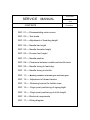
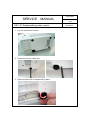
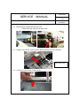
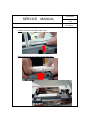
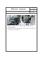
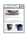
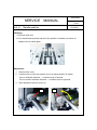
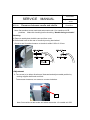
Date:
2011/09/23
SERVICE MANUAL
Page:
1/39
Model:
K65&K85
Original issued: Sept.2011
Date:
2011/09/23
SERVICE MANUAL
CONTENTS
Page:
2/39
Model:
K65&K85
SEC. 01-----Disassembling outer covers
SEC. 02-----Test mode
SEC. 03-----Adjustment of feed-dog height
SEC. 04-----Needle bar height
SEC. 05-----Needle threader height
SEC. 06-----Presser foot height
SEC. 07-----Needle position
SEC. 08-----Clearance between needle and shuttle hook
SEC. 09-----Needle timing to feed-dog
SEC. 10-----Needle timing to shuttle
SEC. 11----- Meshing condition of shuttle gear and lower gear
SEC. 12----- Adjustment of thread tension
SEC. 13----- Retaining bracket for bobbin case
SEC. 14----- Origin point positioning of zigzag bight
SEC. 15----- Origin point positioning of stitch length
SEC. 16-----Electrical components
SEC. 17-----Wiring diagram
Date:
2011/09/23
SERVICE MANUAL
SEC. 01 Disassembling outer covers
1. Lay the machine on its back.
2. Remove screw for rubber feet.
3. Remove rubber foot for adjustment by hand.
Page:
3/39
Model:
K65&K85
Date:
2011/09/23
SERVICE MANUAL
Page:
4/39
Model:
K65&K85
4. Remove base cover.
5. Remove screw for bottom cover.
6. Remove the bottom cover.
Date:
2011/09/23
SERVICE MANUAL
Page:
5/39
Model:
K65&K85
7. Lift the machine and remove screws on needle plate.
8. Remove needle plate.
9. Remove screw for face cover.
Date:
2011/09/23
SERVICE MANUAL
Page:
6/39
Model:
K65&K85
10. Remove screw on rear cover.
11. Remover screw on rear cover which is located near face cover.
12.
Remover cover fixing screw near face cover.
Date:
2011/09/23
SERVICE MANUAL
Page:
7/39
Model:
K65&K85
13. Lift the rear cover using screw driver and remove projection
of the cover from machine body.
14.
Remover the rear cover.
15.
Remover screw from top cover.
Date:
2011/09/23
SERVICE MANUAL
Page:
8/39
Model:
K65&K85
16. Remove fixing screw inside the top cover.
Photo is left side (Lamp cover side) view.
17. Position of the above screw is shown below with the top cover removed.
Foot of top cover
18. Lift the top cover at side of hand wheel.
Date:
2011/09/23
SERVICE MANUAL
Page:
9/39
Model:
K65&K85
Lift the top cover at the side of face cover.
Remove the top cover by lifting it at the same time.
Date:
2011/09/23
SERVICE MANUAL
Page:
10/39
Model:
K65&K85
19. Loosen screw of front cover at the side of hand wheel
so that it may make it easier to re-assemble it.
20. Loosen screw of fixing foot of front cover at the side of hand wheel.
.
Date:
2011/09/23
SERVICE MANUAL
Page:
11/39
Model:
K65&K85
21.
22.
Remove screw of front cover at the side of hand wheel.
Remove tapping screw at needle bar as shown.
Date:
2011/09/23
SERVICE MANUAL
Page:
12/39
Model:
K65&K85
23.
Remove flat cable connected with circuit board from AC circuit board.
24. Remove the front cover from machine body.
Date:
2011/09/23
SERVICE MANUAL
SEC. 02
Page:
13/39
Model:
K65&K85
Test mode
Move bobbin-winder shaft to operating
position.
Press and hold the “Reverse button”.
Turn on sewing machine.
Date:
2011/09/23
SERVICE MANUAL
Page:
14/39
Model:
K65&K85
Model
K65
Release bobbin-winder shaft by the
time when LED of pattern select
button is lit at lowest line.
Model
K85
Release bobbin-winder shaft by the
time when LED display is lit at “00”
as illustrate below.
Date:
2011/09/23
SERVICE MANUAL
Page:
15/39
Model:
K65&K85
K65⇒
Test mode 1
1
K85⇒「00」
Function: Zero feed, three needle positions (L/C/R)
K65⇒
Test mode 2
2
K85⇒「01」
Function: Zero feed, center needle position
K65⇒
Test mode 3
3
K85⇒「02」
Function: 2mm feed, center position, 11stitches forward and back ward.
K65⇒
Test mode 4
4
K85⇒「03」
Function: repeat 4mm feed forward and 3mm feed backward, three needle
positions (L/C/R)
K65⇒
Test mode 5
5
K85⇒「04」
Function: stitch “Darning pattern”
Model
1
6
2
3
K65
4
Model
5
K85
Date:
2011/09/23
SERVICE MANUAL
Page:
16/39
Model:
K65&K85
Test mode 6
K65⇒
6
K85⇒「05」
Function: origin point positioning of zigzag bight and stitch length.
Zigzag width manual adjustment button LED lit when select #6 button
first. For origin point positioning of stitch length, push stitch length
manual adjustment button
Model
K65
Model
K85
Date:
2011/09/23
SERVICE MANUAL
Page:
Model:
K65&K85
Adjustment of feed-dog height
SEC. 03
Checking:
1. Set stitch length at zero feed.
2. Move feed dog to its highest position by turning hand wheel.
Check to see if feed dog height is as illustrated below.
0.9 – 1.1 mm
Adjustment:
1. Remove needle plate. Remove bottom cover.
Adjust feed-dog with reference photo for vertical movement below.
Note: When turning screw, use driver only.
Mounting bracket of feed-dog
d
b
c
e
Viewing from back side.
17/39
Date:
2011/09/23
SERVICE MANUAL
Page:
18/39
Model:
K65&K85
Turn screw (a) to get gap between end (b) of screw (a) and vertical movement
control cam 1 (c).
a
b
b
c
Open front cover and back cover as shown below for adjustment of screw (d).
d
e
Adjust the height of feed-dog by turning screw (d) at side of vertical movement
control cam2 (e) until the height of feed-dog obtains correct position.
After adjustment screw (d), be sure that gap between end (b) of screw (a) and
vertical movement control cam 1 (c) is 0.1mm.
b
c
0.1mm
Date:
2011/09/23
SERVICE MANUAL
19/39
Model:
K65&K85
Needle bar height
SEC. 04
Page:
Note: Make this checking before checking “Needle timing to shuttle” and
”Feed-dog timing (vertical motion)”. Use needle #90/14.
Checking:
1. Select straight stitch at center needle position.
2. Remove presser foot and needle plate, and then remove bobbin case.
3. Replace needle with special needle gauge (L=29 mm).
4. Lower the needle gauge to its lowest position by turning hand wheel by hand.
Check to see if the bottom of the needle gauge aligns with shuttle race pushing
the needle lightly as shown by arrow mark.
Lowest position of
Needle gauge
Needle gauge L = 29 mm
Shuttle race
Adjustment:
1. Remove face cover.
2. Loosen screw (a) of needle bar clamp using hex screw driver and adjust
the height of needle bar.
Date:
2011/09/23
SERVICE MANUAL
Page:
20/39
Model:
K65&K85
a
3. Tighten the screw (a) securely after adjustment. Replace needle gauge with
normal needle #90/14.
4. Check to see if needle threader operates correctly and there is not interference
in vertical movement of needle bar.
Date:
2011/09/23
SERVICE MANUAL
SEC. 05
Page:
21/39
Model:
K65&K85
Needle threader height
Cheking
1. Use needle Singer 90/14.
2. Select straight stitch at center needle position.
3. Raise needle to its highest position by turning hand wheel toward you.
4. Lowering needle threader lever, check and see if hook is inserted into needle hole.
Adjustment
1. Remove face cover.
2. Turning hand wheel by hand, raise needle bar to its highest position.
3. Loosen screw (a) of threader stopper (b).
4. Insert hook into the upper side of needle hole moving the needle bar (c).
5. While holding the above situation, tighten the screw (a) attaching the
threader stopper onto stopper pin (d).
90/14
80/11
70/9
Insert the hook into the
Hook
upper side of needle hole.
Date:
2011/09/23
SERVICE MANUAL
Page:
22/39
Model:
K65&K85
c
c
a
a
d
b
7. If the direction of insert hook is deviated from correct position, adjust the
hook position with the small screw driver in the accessory.
Correct
Date:
2011/09/23
SERVICE MANUAL
SEC. 06
Page:
23/39
Model:
K65&K85
Presser foot height
Checking
6 mm
1.
Lower the feed dog below the needle plate.
2.
Raise the presser foot lever.
3.
Check and see if clearance between needle plate and presser foot is
about 5.6 mm.
Adjustment
1.
Remove the face cover, and raise the presser foot lever.
2.
Loosen the screw (a) and adjust the presser foot height moving the presser bar.
3.
Tighten the screw securely after checking the presser foot is parallel with
the holes for feed dog on the needle plate.
a
Date:
2011/09/23
SERVICE MANUAL
SCE. 07
Page:
24/39
Model:
K65&K85
Needle position
Checking:
1. Set test mode at 2.
2. Turn hand wheel by hand and see if the position of needle is at center of
needle hole on needle plate.
Adjustment:
1.
Remove face cover.
2.
Loosen screw (a) and turn plastic nut (b) to adjust position of needle.
Turn to clockwise direction --- needle moves to left side
Turn to counter clockwise direction --- needle moves to right side
3.
After adjustment secure screw (a).
a
b
Date:
2011/09/23
SERVICE MANUAL
Page:
Clearance between needle and shuttle
SEC.08
25/39
Model:
K65&K85
Note: Set machine at test mode and select test mode 1 for needle at L/C/R
positions.
Make this checking before checking “Needle timing to shuttle”.
Checking:
1. Remove needle plate, bobbin case and face cover.
2. Shift shuttle hook at the rear of needle by turning hand wheel.
Check to see if needle clearance to shuttle is within 0.05 to 0.15 mm.
Adjustment:
1. Turn screw (a) to either direction as illustrated and adjust needle position by
moving support shaft back and forth.
To decrease clearance, turn screw to counter-clockwise.
a
Note: Set machine at test mode and select test mode 1 for needle at L/C/R.
Date:
2011/09/23
SERVICE MANUAL
Page:
26/39
Model:
K65&K85
2. If needle clearance to shuttle at right and left position is not same, adjust position
of fulcrum (b) for needle swing support.
Loosen two screws (c) located under bottom of support plate and adjust position
of fulcrum (b).
b
C
b
C
b
b
If needle touches with shuttle at left side,
If it touches at right side, adjust position
adjust position of fulcrum (b) for
of fulcrum (b) for needle swing
needle swing support to the right.
support to the left.
3. After adjustment, tighten two screws (c) securely.
Date:
2011/09/23
SERVICE MANUAL
SEC. 09
Page:
27/39
Model:
K65&K85
Needle timing to feed-dog
Note: After adjustment, be sure to follow “Needle timing to shuttle”.
As horizontal and vertical feed motion is unitized on this model, adjustment of feed
timing is as follows:
Checking:
1. Bring needle bar to its highest position by turning hand wheel.
2. Check to see if feed dog starts to move when needle starts to go down by
turning hand wheel towards you.
Feed dog starts to move a little bit
earlier than when needle starts to
go down.
Adjustment:
1. Turn off the machine with feed amount set at maximum for adjustment.
2. Loosen one of two screws (b) of timing belt gear (a) on main shaft.
Turn hand wheel by hand and stop it when needle tip arrives at the surface of
needle plate. Holding this position, loosen the other screw so that the gear may
be perfectly freed from the main shaft.
a
b
Date:
2011/09/23
SERVICE MANUAL
Page:
28/39
Model:
K65&K85
3. Holding such condition, turn belt gear at the side of lower shaft by hand, so
that teeth of feed dog may be at the same level of needle plate.
Holding this position, tighten one of screws of belt gear on the main shaft.
4. Turning the machine by hand, check to see if feed timing is approximately
as explained above.
5. Tighten two screws (b) on the belt gear securely after adjustment.
Date:
2011/09/23
SERVICE MANUAL
SEC. 10
Needle timing to shuttle
Page:
29/39
Model:
K65&K85
Check “Feed timing (vertical movement)” and “Needle height” beforehand.
Checking
1. Set machine at test mode and select mode 1.
2. Remove needle plate. Check to see if needle is not bent.
3. Move needle to left position by turning hand wheel. Raise needle from its lowest
position slowly and check if distance is as illustrated below when point of shuttle
hook aligns with right side of needle.
Needle plate
0.5 to 1.2
point of shuttle hook
Shuttle race
Adjustment
1. Remove front cover and bottom cover.
Remove “Drop feed control unit”(a) by removing two screws (a &b) on shuttle
base.
c
b
a
Date:
2011/09/23
SERVICE MANUAL
Page:
30/39
Model:
K65&K85
2. While needle is placed around the lower area, loosen a screw, but not the one
(d) which can be touched for adjustment.
Holding this position, adjust needle timing shuttle by turning hand wheel with
a tool inserted into the screw hole as illustrated below.
e
3.Check to see if the distance is correct as illustrated above.
Tighten two screws securely after adjustment.
Date:
2011/09/23
SERVICE MANUAL
SEC. 11
Meshing condition of shuttle gear and lower gear
Page:
31/39
Model:
K65&K85
1. Check meshing condition of gears after adjustment.
Check play of the gear at 4 positions –each 90 degree angle of 1 rotation
of shuttle race.
No play on 2 positions to save too loose condition – play on other 2 positions
to save too tight condition.
2
Adjustment of play between shuttle gear and lower shaft gear is made by
turning eccentric ball bushing (f).
*loosen screw (g) on pressing plate so that the ball bushing (f) may be turned.
*Turn the ball bushing (f) in either way by using concave portion.
*The ball bushing is to be placed with mark (h) positioned at upper side within angle
of 180 degrees
h
g
f
3. Tighten the screw (C) securely after adjustment.
Date:
2011/09/23
SERVICE MANUAL
SEC. 12
Adjustment of thread tension
Page:
32/39
Model:
K65&K85
Adjustment of needle thread tension is explained below.
1. Remove face and front covers.
2. Pull out outer dial (a) on needle thread tension mechanism.
Remove star-shaped plate spring (c) on inner dial (b).
a
c
b
3. Pull out the inner dial (b) and turn adjustment nut (d) to adjust tension at approximately
60 g using span polyester thread No. 60 and tension gauge.
d
Date:
2011/09/23
SERVICE MANUAL
Page:
33/39
Model:
K65&K85
4. Insert the inner dial (b) into place after adjustment. Fix wall portion (h)of the inner
dial into position where it is around opposite side of pipe knock pin (e).
e
h
b
Though tension value may be deviated a little from the one adjusted on section 3,,
Re-adjust it in last step.
5. Outside surface of inner dial (b) is knurled and inside surface of outer dial (a)
is partly knurled. The knurled portions of both dials are meshed each other.
Knurled portion
Date:
2011/09/23
SERVICE MANUAL
Page:
34/39
Model:
K65&K85
6. Make sure where indicator of the front cover is to be positioned on thread guide plate
beforehand. Insert the outer dial (a) so that the center position may be aligned with
indicator on front cover .
a
7. Re-confirm tension value using the tension gauge in the position above.
If adjustment is needed, slide the outer dial (a) to outside to release knurled portion
and turn it either way and mesh it again.
f
After adjustment is completed, insert plate spring (f) into V groove on the outer dial
(a) and tighten screw securely. This position is the one for the indicator of the
front cover.
Date:
2011/09/23
SERVICE MANUAL
SEC. 13
Page:
35/39
Model:
K65&K85
Retaining bracket for bobbin case
1. Remove needle plate.
2. Loosen screw (a & b) and adjust the position of retaining bracket until the
projection (c) of bobbin case can be positioned against the plate spring.
3. Place needle plate into position、check clearance between projection of bobbin
case when move bobbin case in reverse rotation.
Clearance is 1 to 2 mm.
b
a
c
Plate spring
Retainer for reverse rotation
Date:
2011/09/23
SERVICE MANUAL
SEC. 14
Origin point positioning of zigzag bight
Page:
36/39
Model:
K65&K85
This section is to explain how to restore meshing position of pinion gear and
operation gear of step motor for zigzag bight.
1. Remove face and front covers.
2. Turn on the machine and set test mode at 05.(see section 02). Push zigzag
bight adjustment switch on operation panel and confirm if LED is lit.
3. Loosen two screws fixing pinion of step motor onto motor shaft. There is a dent
on the pinion gear (b) as well as on operation gear (a).
These dents are meshed at the position where they face each other.
d
a
b
凹み
凹み
*Step motor is energized in this position.
Push start switch a few times for confirmation.
4. Holding this situation, turn the pinion gear (b) fully clockwise until the projection
(c) touches with rotation stopper (d) and tighten the screw on the pinion gear.
d
c
Date:
2011/09/23
SERVICE MANUAL
SCE. 15
Page:
37/39
Model:
K65&K85
Origin point positioning of stitch length
This section is to explain how to restore meshing position of pinion gear
and operation gear of step motor for feed.
4. Remove face and front covers.
5. Turn on the machine and set test mode at 05.(see section 02). Push feed
adjustment switch on operation panel and confirm if LED is lit.
6. Loosen two screws fixing pinion of step motor onto motor shaft. There is a dent on
the pinion gear (b) as well as on operation gear (a). These dents are meshed at the
position where they face each other.
a
b
*Step motor is energized in this position. Push switch a few times
for confirmation.
4. Holding this situation, turn the pinion gear (b) fully clockwise until the projection
(c) touches with rotation stopper (d) and tighten the screw on the pinion gear.
d
C
Date:
2011/09/23
SERVICE MANUAL
SEC. 16
Page:
38/39
Model:
K65&K85
Electronic components area
List of main circuit boards for K series
K65
Transformer
K85
120V
230V
120V
230V
87514
87519
87514
87519
84120
84125
84130
CPU circuit board
Power supply circuit board
84120
84125
84123
SW control circuit board
84124
85522
Stepping motors
AC board
For 100/120v
For 230v
CPU
board
SW board
For K-65
SW board
For K-85
Date:
2011/09/23
SERVICE MANUAL
SEC. 17
Wiring diagram
Page:
39/39
Model:
K65&K85