1
ORDER NO.DSC1303007CE
B26
Digital Camera
Model No. DMC-TZ37EC
DMC-TZ40EB
DMC-TZ40EE
DMC-TZ40EF
DMC-TZ40EG
DMC-TZ40EP
DMC-TZ40EA
DMC-TZ40GA
DMC-TZ40GC
DMC-TZ40GN
DMC-TZ41EG
DMC-ZS27PC
DMC-ZS30P
DMC-ZS30PC
DMC-ZS30PU
DMC-ZS30GK
DMC-ZS30GH
DMC-ZS30GT
Colours
(S)....................Silver Type (only DMC-TZ40EB/EE/EF/
EG/EP, TZ41, ZS30P/PC/GK)
(K)....................Black Type
(W)....................White Type (except DMC-TZ40EA,
TZ37EB/EC, ZS30PC/PU, ZS27P/PC)
(R)....................Red Type (except DMC-TZ37EB/EC,
ZS30P/PC/PU/GH, ZS27P/PC)
© Panasonic Corporation 2013.
Unauthorized copying and distribution is a violation
of law.
TABLE OF CONTENTS
PAGE
1 Safety Precautions -----------------------------------------------3
1.1. General Guidelines ----------------------------------------3
1.2. Leakage Current Cold Check ---------------------------3
1.3. Leakage Current Hot Check (See Figure 1)---------3
1.4. How to Discharge the Capacitor on Flash
P.C.B.----------------------------------------------------------4
2 Warning --------------------------------------------------------------5
2.1. Prevention of Electrostatic Discharge (ESD)
to Electrostatic Sensitive (ES) Devices ---------------5
2.2. How to Recycle the Lithium Ion Battery (U.S.
Only)-----------------------------------------------------------5
2.3. How to Replace the Lithium Battery -------------------6
3 Service Navigation------------------------------------------------7
3.1. Introduction --------------------------------------------------7
3.2. Service Navigation -----------------------------------------7
3.3. Service Notes -----------------------------------------------9
3.4. General Description About Lead Free Solder
(PbF) -------------------------------------------------------- 10
3.5. How to Define the Model Suffix (NTSC or PAL
model)------------------------------------------------------- 11
4 Specifications ---------------------------------------------------- 16
5 Location of Controls and Components------------------ 17
6 Service Mode ----------------------------------------------------- 18
6.1. Error Code Memory Function ------------------------- 18
7 Troubleshooting Guide---------------------------------------- 22
7.1. Failure Diagnosis of GPS (Except: TZ37EB/
EC, ZS27P/PC and ZS30GK)------------------------- 22
7.2. Failure Diagnosis of Wi-Fi------------------------------ 24
7.3. Failure Diagnosis of NFC ------------------------------ 25
8 Service Fixture & Tools --------------------------------------- 26
8.1. Service Fixture and Tools ------------------------------ 26
8.2. When Replacing the Main P.C.B. -------------------- 26
8.3. Service Position ------------------------------------------ 27
9 Disassembly and Assembly Instructions --------------- 28
9.1. Disassembly Flow Chart-------------------------------- 28
9.2. P.C.B. Location ------------------------------------------- 28
9.3. Disassembly Procedure -------------------------------- 29
9.4. Lens Disassembly Procedure ------------------------- 37
9.5. Assembly Procedure for Lens (Revised
Version) ----------------------------------------------------- 41
9.6. Removal of the MOS Unit ------------------------------ 47
10 Measurements and Adjustments -------------------------- 48
10.1. Introduction ------------------------------------------------ 48
10.2. Before Disassembling the unit ------------------------ 48
10.3. Details of Electrical Adjustment----------------------- 50
10.4. After Adjustment------------------------------------------ 56
11 Maintenance ------------------------------------------------------ 57
11.1. Cleaning Lens, Viewfinder and LCD Panel -------- 57
12 Block Diagram --------------------------------------------------- 59
12.1. Overall Block Diagram ---------------------------------- 59
12.2. System Control Block Diagram ----------------------- 60
PAGE
12.3. Audio/Video Process/ HDMI Block Diagram ------ 61
12.4. Lens Drive Block Diagram----------------------------- 62
12.5. Power Block Diagram----------------------------------- 63
13 Wiring Connection Diagram -------------------------------- 64
13.1. Interconnection Schematic Diagram ---------------- 64
2
1 Safety Precautions
1.1.
General Guidelines
1.3.
1. IMPORTANT SAFETY NOTICE
There are special components used in this equipment
which are important for safety. These parts are marked by
2.
3.
4.
5.
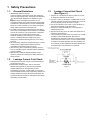
1. Plug the AC cord directly into the AC outlet. Do not use
an isolation transformer for this check.
2. Connect a 1.5kΩ, 10 W resistor, in parallel with a 0.15μF
capacitor, between each exposed metallic part on the set
and a good earth ground, as shown in Figure 1.
3. Use an AC voltmeter, with 1 kΩ/V or more sensitivity, to
measure the potential across the resistor.
4. Check each exposed metallic part, and measure the
voltage at each point.
5. Reverse the AC plug in the AC outlet and repeat each of
the above measurements.
6. The potential at any point should not exceed 0.75 V RMS.
A leakage current tester (Simpson Model 229 or
equivalent) may be used to make the hot checks, leakage
current must not exceed 1/2 mA. In case a measurement
is outside of the limits specified, there is a possibility of a
shock hazard, and the equipment should be repaired and
rechecked before it is returned to the customer.
in the Schematic Diagrams, Circuit Board Layout,
Exploded Views and Replacement Parts List. It is
essential that these critical parts should be replaced with
manufacturer's specified parts to prevent X-RADIATION,
shock fire, or other hazards. Do not modify the original
design without permission of manufacturer.
An Isolation Transformer should always be used during
the servicing of AC Adaptor whose chassis is not isolated
from the AC power line. Use a transformer of adequate
power rating as this protects the technician from
accidents resulting in personal injury from electrical
shocks. It will also protect AC Adaptor from being
damaged by accidental shorting that may occur during
servicing.
When servicing, observe the original lead dress. It a short
circuit is found, replace all parts which have been
overheated or damaged by the short circuit.
After servicing, see to it that all the protective devices
such as insulation barriers, insulation papers shields are
properly installed.
After servicing, make the following leakage current
checks to prevent the customer from being exposed to
shock hazards.
1.2.
Leakage Current Hot Check
(See Figure 1)
Leakage Current Cold Check
1. Unplug the AC cord and connect a jumper between the
two prongs on the plug.
2. Measure the resistance value, with an ohmmeter,
between the jumpered AC plug and each exposed
metallic cabinet part on the equipment such as
screwheads, connectors, control shafts, etc. When the
exposed metallic part has a return path to the chassis, the
reading should be between 1MΩ and 5.2MΩ. When the
exposed metal does not have a return path to the chassis,
Figure 1
the reading must be infinity.
3
1.4.
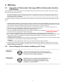
How to Discharge the Capacitor on Flash P.C.B.
CAUTION:
1. Be sure to discharge the capacitor on Flash P.C.B.
2. Be careful of the high voltage circuit on Flash P.C.B. when servicing.
[Discharging Procedure]
1. Refer to the disassemble procedure and remove the necessary parts/unit.
2. Install the insulation tube onto the lead part of Resistor (ERG5SJ102:1kΩ /5W).
(an equivalent type of resistor may be used.)
3. Place a resistor between both terminals of capacitor on the Flash P.C.B. for approx. 5 seconds.
4. After discharging, confirm that the capacitor voltage is lower than 10V using a voltmeter.
Fig. F1
4
2 Warning
2.1.
Prevention of Electrostatic Discharge (ESD) to Electrostatic Sensitive
(ES) Devices
Some semiconductor (solid state) devices can be damaged easily by static electricity. Such components commonly are called
Electrostatically Sensitive (ES) Devices.
The following techniques should be used to help reduce the incidence of component damage caused by electrostatic discharge
(ESD).
1. Immediately before handling any semiconductor component or semiconductor-equipped assembly, drain off any ESD on your
body by touching a known earth ground. Alternatively, obtain and wear a commercially available discharging ESD wrist strap,
which should be removed for potential shock reasons prior to applying power to the unit under test.
2. After removing an electrical assembly equipped with ES devices, place the assembly on a conductive surface such as
aluminum foil, to prevent electrostatic charge buildup or exposure of the assembly.
3. Use only a grounded-tip soldering iron to solder or unsolder ES devices.
4. Use only an antistatic solder removal device. Some solder removal devices not classified as
can
generate electrical charge sufficient to damage ES devices.
5. Do not use freon-propelled chemicals. These can generate electrical charges sufficient to damage ES devices.
6. Do not remove a replacement ES device from its protective package until immediately before you are ready to install it. (Most
replacement ES devices are packaged with leads electrically shorted together by conductive foam, aluminum foil or
comparable conductive material).
7. Immediately before removing the protective material from the leads of a replacement ES device, touch the protective material
to the chassis or circuit assembly into which the device will be installed.
CAUTION:
Be sure no power is applied to the chassis or circuit, and observe all other safety precautions.
8. Minimize bodily motions when handling unpackaged replacement ES devices. (Otherwise harmless motion such as the
brushing together of your clothes fabric or the lifting of your foot from a carpeted floor can generate static electricity (ESD)
sufficient to damage an ES device).
2.2.
How to Recycle the Lithium Ion Battery (U.S. Only)
5
2.3.
2.3.1.
How to Replace the Lithium Battery
Replacement Procedure
1. Remove the Top P.C.B. (Refer to Disassembly Procedures.)
2. Unsolder the Lithium battery (Ref. No.
at foil side of Top P.C.B.) and then replace it into new one.
Note:
The lithium battery is a critical component.
(Type No.: ML-421S/DN Manufactured by Energy Company, Panasonic Corporation.)
It must never be subjected to excessive heat or discharge.
It must therefore only be fitted in equipment designed specifically for its use.
Replacement batteries must be of the same type and manufacture.
They must be fitted in the same manner and location as the original battery, with the correct polarity contacts observed.
Do not attempt to re-charge the old battery or re-use it for any other purpose.
It should be disposed of in waste products destined for burial rather than incineration.
Note:
Above caution is applicable for a battery pack which is for DMC-TZ37/TZ40/TZ41/ZS27/ZS30 series, as well.
6
3 Service Navigation
3.1.
Introduction
This service manual contains technical information, which will allow service personnel's to understand and service this model.
Please place orders using the parts list and not the drawing reference numbers.
If the circuit is changed or modified, the information will be followed by service manual to be controlled with original service manual.
3.2.
Service Navigation
3.2.1.
About lens block
The image sensor (MOS) unit which are connected to the lens unit with 3 screws. 2 of these 3 screws are locked, after performing
the Optical tilt adjustment. During servicing, if one of MOS fixing screws are loosened, the Optical tilt adjustment must be
performed. (About the Optical tilt adjustment, refer to the "9.3.2 Adjustment Specifications" for details.)
NOTE:
It is necessary to use the "DSC_Tilt" software to allow the "Optical tilt adjustment".
The Adjustment software "DSC_Tilt" is available at "TSN Website".
7
3.2.2.
About VENUS ENGINE (IC6001) < Located on the Main P.C.B. >
• The VENUS ENGINE (IC6001) consists of two IC chips, which are fixed together with solder.
(It is so called, "Package On Package" type of IC.)
Caution:
• During servicing, do not press down hard on the surface of IC6001.
3.2.3.
About protection sheet
The hardening gel has been applied to the rear case and LCD during factory process.
If the hardening gel is damaged when removing the rear case unit during servicing, remove the hardening gel completely and attach
the protection sheet.
8
3.3.
Service Notes
3.3.1.
About Wi-Fi Function
3.3.2.
Important Notice of Servicing
This Camera unit has the personal information of wireless LAN connection the customer has registered.
For the protection of private information, please erase the personal information after the completion of repair by "INITIAL
SETTING".
In addition, please print out the following documents, and pass to the customer with the Camera unit.
Printing Material [Leaflet for Customer]
Printing Material [Leaflet for Customer]
9
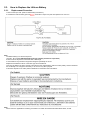
3.4.
General Description About Lead Free Solder (PbF)
The lead free solder has been used in the mounting process of all electrical components on the printed circuit boards used for this
equipment in considering the globally environmental conservation.
The normal solder is the alloy of tin (Sn) and lead (Pb). On the other hand, the lead free solder is the alloy mainly consists of tin
(Sn), silver (Ag) and Copper (Cu), and the melting point of the lead free solder is higher approx.30 °C (86 °F) more than that of the
normal solder.
Definition of PCB Lead Free Solder being used
The letter of
is printed either foil side or components side on the P.C.B. using the lead free solder.
(See right figure)
Service caution for repair work using Lead Free Solder (PbF)
• The lead free solder has to be used when repairing the equipment for which the lead free solder is used.
•
•
•
•
(Definition: The letter of
is printed on the P.C.B. using the lead free solder.)
To put lead free solder, it should be well molten and mixed with the original lead free solder.
Remove the remaining lead free solder on the P.C.B. cleanly for soldering of the new IC.
Since the melting point of the lead free solder is higher than that of the normal lead solder, it takes the longer time to melt the
lead free solder.
• Use the soldering iron (more than 70W) equipped with the temperature control after setting the temperature at 350±30 degrees
C (662±86 °F).
Recommended Lead Free Solder (Service Parts Route.)
• The following 3 types of lead free solder are available through the service parts route.
RFKZ03D01KS-----------(0.3mm 100g Reel)
RFKZ06D01KS-----------(0.6mm 100g Reel)
RFKZ10D01KS-----------(1.0mm 100g Reel)
Note:
* Ingredient: tin (Sn) 96.5%, silver (Ag) 3.0%, Copper (Cu) 0.5%, Cobalt (Co) / Germanium (Ge) 0.1 to 0.3%
10
3.5.
How to Define the Model Suffix (NTSC or PAL model)
There are eight kinds of DMC-TZ37/TZ40/TZ41/ZS27/ZS30, regardless of the colours.
• a) DMC-TZ40 (Japan domestic model.)
• b) DMC-ZS27PC, ZS30P/PC
• c) DMC-TZ37EC, TZ40EB/EF/EG/EP, TZ41EG
• d) DMC-TZ40EE
• e) DMC-TZ40GN
• f) DMC-ZS30GT
• g) DMC-ZS30GK
• h) DMC-TZ40GA/GC, ZS30PU/GH
What is the difference is that the "INITIAL SETTINGS" data which is stored in Flash ROM mounted on Main P.C.B.
3.5.1.
Defining methods
To define the model suffix to be serviced, refer to the nameplate which is putted on the bottom side of the Unit.
Note:
After replacing the Main P.C.B., be sure to achieve adjustment.
11
3.5.2.
INITIAL SETTINGS:
After replacing the Main P.C.B., make sure to perform the initial settings after achieving the adjustment by ordering the following
procedure in accordance with model suffix of the unit.
1. IMPORTANT NOTICE:
Before proceeding Initial settings, be sure to read the following CAUTIONS.
2. PROCEDURES:
• Precautions: Read the above "CAUTION 1" and "CAUTION 2", carefully.
• Preparation:
1. Attach the Battery to the unit.
2. Set the mode dial to the PROGRAM AE mode.
Note: If the mode dial position is other than PROGRAM AE mode, it does not display the initial settings menu.
• Step 1. The temporary cancellation of "INITIAL SETTINGS":
While keep pressing "UP of Cursor button" and MOTION PICTURE button simultaneously, turn the Power on.
• Step 2. The cancellation of "INITIAL SETTINGS":
Press the PLAYBACK button.
Press "UP of Cursor button" and MOTION PICTURE button simultaneously, then turn the Power off.
• Step 3. Turn the Power on:
Turn the Power on.
12
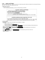
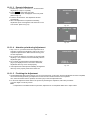
• Step 4. Display the "INITIAL SETTINGS" menu:
Note: If the unit is other than PROGRAM AE mode, it does not display the initial settings menu.
While keep pressing MENU/SET and "RIGHT of Cursor button" simultaneously, turn the Power off.
The "INITIAL SETTINGS" menu is displayed.
There are two kinds of "INITIAL SETTINGS" menu form as follows:
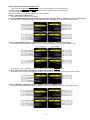
[CASE 1. After replacing MAIN P.C.B.]
There are four kinds of menu from as follows:
[Except for "DMC-TZ40EG, EF, EB, EP, GA, ZS30GK, TZ41, TZ37 and ZS27" models : (VEK0U05 is used as a Main P.C.B.)]
When Main P.C.B. has just been replaced, all of the model suffix are displayed as follows. (Four pages in total)
[Only for "DMC-TZ40EG, EF, EB, EP, GA and TZ41" models : (VEK0U06 is used as a Main P.C.B.)]
When Main P.C.B. has just been replaced, only 8 model suffix are displayed as follows. (Two pages in total)
To display the "TZ41" model suffix, choose the "EG" area and press the DELETE button.
[Only for "DMC-TZ37" models : (VEK0U09 is used as a Main P.C.B.)]
When Main P.C.B. has just been replaced, the following model suffix are displayed as follows. (Two pages in total)
[Only for "DMC-ZS27 and ZS30GK" models : (VEK0U10 is used as a Main P.C.B.)]
When Main P.C.B. has been replaced, the following model suffix are displayed as follows. (Four pages in total)
13
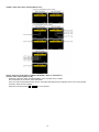
[CASE 2. Other than "After replacing Main P.C.B."]
• Step 5. Chose the model suffix in "INITIAL SETTINGS": (Refer to "CAUTION 1")
[Caution: After replacing Main P.C.B.]
(Especially, other than "DMC-TZ40EG/EF/EB/EP, TZ41 and DMC-TZ37" models)
The model suffix can be chosen, JUST ONE TIME.
Once one of the model suffix have been chosen, the model suffix lists will not be displayed, thus, it can not be changed.
Therefore, select the area carefully.
Select the area with pressing "UP / DOWN of Cursor buttons".
14
• Step 6. Set the model suffix at "INITIAL SETTINGS":
Press the "RIGHT of Cursor buttons".
The only set area is displayed. Press the "RIGHT of Cursor buttons" after confirmation.
(The unit is powered off automatically.)
• Step 7. CONFIRMATION:
Confirm the display of "PLEASE SET THE CLOCK" in concerned language when the unit is turned on again.
When the unit is connected to PC with USB cable, it is detected as removable media.
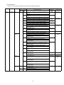
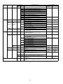
1) As for your reference, major default setting condition is as shown in the following table.
• Default setting (After "INITIAL SETTINGS")
a)
b)
c)
d)
e)
f)
g)
h)
i)
j)
k)
l)
m)
n)
o)
p)
q)
r)
s)
MODEL
DMC-TZ40 (Japan domestic model)
DMC-TZ37EC
DMC-TZ40EB
DMC-TZ40EE
DMC-TZ40EF
DMC-TZ40EG
DMC-TZ40EP
DMC-TZ40EA
DMC-TZ40GA
DMC-TZ40GC
DMC-TZ40GN
DMC-TZ41EG
DMC-ZS27PC
DMC-ZS30P
DMC-ZS30PC
DMC-ZS30PU
DMC-ZS30GK
DMC-ZS30GH
DMC-ZS30GT
VIDEO OUTPUT
NTSC
PAL
PAL
PAL
PAL
PAL
PAL
PAL
PAL
PAL
PAL
PAL
NTSC
NTSC
NTSC
NTSC
PAL
PAL
NTSC
LANGUAGE
Japanese
English
English
Russian
French
English
English
Russian
English
English
English
English
English
English
English
Spanish
Chinese (simplified)
English
Chinese (Traditional)
15
DATE
Year/Month/Date
Date/Month/Year
Date/Month/Year
Date/Month/Year
Date/Month/Year
Date/Month/Year
Date/Month/Year
Date/Month/Year
Date/Month/Year
Date/Month/Year
Date/Month/Year
Date/Month/Year
Month/Date/Year
Month/Date/Year
Month/Date/Year
Month/Date/Year
Year/Month/Date
Date/Month/Year
Year/Month/Date
REMARKS
No Underwater mode.
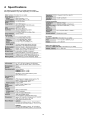
4 Specifications
The following specification is for DMC-ZS27PC/30PC.
Some specifications may differ depending on model suffix.
16
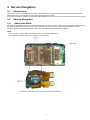
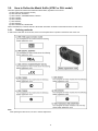
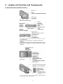
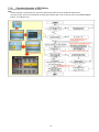
5 Location of Controls and Components
The following description is for DMC-ZS27PC/30PC.
Some description may differ depending on model suffix.
17
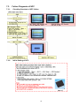
6 Service Mode
6.1.
Error Code Memory Function
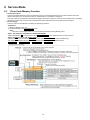
1. General description
This unit is equipped with history of error code memory function, and can be memorized 16 error codes in sequence from the
latest. When the error is occurred more than 16, the oldest error is overwritten in sequence.
The error code is not memorized when the power supply is shut down forcibly (i.e.,when the unit is powered on by the battery,
the battery is pulled out) The error code is memorized to Flash ROM when the unit has just before powered off.
2. How to display
The error code can be displayed by ordering the following procedure:
• Preparation:
1. Attach the Battery to the unit.
2. Set the mode dial to the PROGRAM AE mode.
Note:
*Since this unit has built-in memory, it can be performed without inserting Memory Card.
• Step 1. The temporary cancellation of "INITIAL SETTINGS":
While keep pressing "UP of Cursor button" and MOTION PICTURE button simultaneously, turn the Power on.
• Step 2. Execute the error code display mode:
Press the "LEFT of Cursor button", MENU/SET button and MOTION PICTURE button simultaneously.
The display is changed as shown below when the above buttons are pressed simultaneously.
Normal display → Error code display → CAMERA INFO → Normal display → .....
18
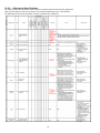
3. Error Code List
The error code consists of 8 bits data and it shows the following information.
Attribute
LENS
Main item
Lens drive
Sub item
OIS
Zoom
(C.B.)
Focus
Lens
Error code
Contents (Upper)
Error Indication
High
Low 4
Check point (Lower)
Detecting
Part/Circuit
4bits
bits
device
18*0
1000 PSD (X) error. Hall element (X axis) position detect error in
OIS X
LENSu NG
OIS unit.
OIS Unit
2000 PSD (Y) error. Hall element (Y axis) position detect error in
OIS Y
OIS unit.
OIS Unit
3000 GYRO (X) error. Gyro (IC7101) detect error on Main P.C.B.
GYRO X
GYRO NG
IC7101 (Gyro element) or IC6001 (VENUS ENGINE)
4000 GYRO (Y) error. Gyro (IC7101) detect error on Main P.C.B.
GYRO Y
IC7101 (Gyro element) or IC6001 (VENUS ENGINE)
5000 GYRO (R) error, Gyro (IC7101) detect error on Main P.C.B.
GYRO R
IC7101 (Gyro element) or IC6001 (VENUS ENGINE)
6000 Drive voltage (X) error.
OISX REF
LENSu/LENS
FPC
LENS Unit, LENS flex breaks, IC6001(VENUS ENGINE)
AD value error, etc.
7000 Drive voltage (Y) error.
OISY REF
LENS Unit, LENS flex breaks, IC6001(VENUS ENGINE)
AD value error, etc.
8000 OIS GYRO - Digital communication error.
(No indication) (No indication)
IC7101 (Gyro element) or IC6001 (VENUS ENGINE)
0?10 Collapsible barrel Low detect error
ZOOM L
ZOOMm/
LENSu
(Collapsible barrel encoder always detects High.)
Mechanical lock, FP9005-(11) signal line or IC6001
(VENUS ENGINE)
0?20 Collapsible barrel High detect error
ZOOM H
(Collapsible barrel encoder always detects Low.)
Mechanical lock, FP9005-(11) signal line or IC6001
(VENUS ENGINE)
0?30 Zoom motor sensor error.
ZOOM ENC
Mechanical lock, FP9005-(6), (9) signal line or IC6001
(VENUS ENGINE)
0?40 Zoom motor sensor error. (During monitor mode.)
Mechanical lock, FP9005-(6), (9) signal line or IC6001
(VENUS ENGINE)
0?50 Zoom motor sensor error. (During monitor mode with slow
speed.)
Mechanical lock, FP9005-(6), (9) signal line or IC6001
(VENUS ENGINE)
0?60 Phase error or operation failure of zoom Lens/motor/
encoder. (IMPACT)
Mechanical lock, zoom encoder.
FOCUS L
LENS FPC/
0?01 HP High detect error
DSP
(Focus encoder always detects High, and not becomes
Low)
Mechanical lock, FP9005-(11) signal line or IC6001
(VENUS ENGINE)
FOCUS H
0?02 HP Low detect error
(Focus encoder always detects Low, and not becomes
High)
Mechanical lock, FP9005-(11) signal line or IC6001
(VENUS ENGINE)
18*1
0000 Power ON time out error.
LENS DRV
LENSu
Lens drive system
18*2
0000 Power OFF time out error.
Lens drive system
19
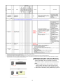
Attribute
HARD
Main item
Sub item
Adj.History
OIS
VENUS
A/D
FLASH
ROM
(EEPROM
Area)
Flash
FLASH
ROM
(EEPROM
Area)
Error code
High
Low 4
4bits
bits
19*0
2000
3000
4000
5000
8000
9000
A000
B000
C000
D000
E000
28*0
0000
2B*0
0001
0002
0005
SOFT
SYSTEM
RTC
2C*0
0001
CPU
Reset
30*0
CPU,
ASIC hard
Stop
38*0
0001
|
0007
0001
0002
0100
0200
Wi-Fi
3A*0
0300
0008
Operation
Memory
area
Power on
3B*0
0000
Zoom
Zoom
3C*0
0000
35*0
35*1
35*2
0000
|
FFFF
0000
0000
3211
|
3214
0001
|
FFFF
Contents (Upper)
Check point (Lower)
OIS adj. Yaw direction amplitude error (small)
OIS adj. Pitch direction amplitude error (small)
OIS adj. Yaw direction amplitude error (large)
OIS adj. Pitch direction amplitude error (large)
OIS adj. Yaw direction off set error
OIS adj. Pitch direction off set error
OIS adj. Yaw direction gain error
OIS adj. Pitch direction gain error
OIS adj. Yaw direction position sensor error
OIS adj. Pitch direction position sensor error
OIS adj. other error
Flash charging error.
IC6001-(AC18) signal line or Flash charging circuit
EEPROM read error
IC6002 (Flash ROM)
EEPROM write error
IC6002 (Flash ROM)
Firmware version up error
Replace the firmware file in the Memory Card.
SYSTEM IC initialize failure error
Communication between IC6001 (VENUS ENGINE) and
IC9101 (SYSTEM)
NMI reset
Non Mask-able Interrupt
(30000001-30000007 are caused by factors)
Camera task finish process time out.
Communication between Lens system and IC6001
(VENUS ENGINE)
Camera task invalid code error.
IC6001 (VENUS ENGINE)
File time out error in recording motion image
IC6001 (VENUS ENGINE)
File data cue send error in recording motion image
IC6001 (VENUS ENGINE)
Single or burst recording brake time out.
work area partitioning failure
USB dynamic memory securing failure when connecting
Flash ROM processing early period of camera during
movement.
Imperfect zoom lens processing
Zoom lens
Software error
(0-7bit : command, 8-15bit : status)
Error Indication
Detecting
Part/Circuit
device
OIS ADJ
OIS ADJ
STRB CHG
FROM RE
STRB P.C.B./
FPC
FROM
FROM WR
FROM
(No indication) (No indication)
SYS INIT
MAIN P.C.B.
NMI RST
MAIN P.C.B.
LENS COM
LENSu/DSP
DSP
DSP
(No indication) (No indication)
INIT
(No indication)
ZOOM
ZOOMm/
LENSu
DSP
DSP
Though record preprocessing is necessary, it is not called.
Though record preprocessing is necessary, it is not
(No indication) (No indication)
completed.
Wi-Fi related errors:
*Generally, above are unable to specified the, which cannot be used for malfunction
diagnosis.
20
Important notice about "Error Code List"
1) About "*" indication:
The third digit from the left is different as follows.
+.In case of 0 (example: 18 0 01000)
When the third digit from the left shows "0", this error occurred under the condition of INITIAL SETTINGS has been completed.
It means that this error is occurred basically at user side.
+.In case of 8 (example: 18 8 01000)
When the third digit from the left shows "8", this error occurred under the condition of INITIAL SETTINGS has been released.
(Example; Factory assembling-line before unit shipment, Service mode etc.)
It means that this error is occurred at service side.
2) About "?" indication: ("18*0 0?01" to "18*0 0?50"):
The third digit from the right shows one of the hexadecimal ("0" to "F") character.
4. How to exit from Error Code display mode:
Simply, turn the power off. (Since Error code display mode is executed under the condition of temporary cancellation of "INITIAL
SETTINGS", it wake up with normal condition when turn off the power.)
Note:
The error code can not be initialized.
21
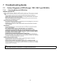
7 Troubleshooting Guide
7.1.
7.1.1.
Failure Diagnosis of GPS (Except: TZ37, ZS27 and ZS30GK)
Checking Method of GPS failure
GENERAL DESCRIPTION
Note:
DMC-TZ37EB/EC, ZS27P/PC and ZS30GK do not equipped with GPS function.
22
7.1.2.
Checking flowchart of GPS failure
The checking flowchart of GPS failure is as follows:
Note:
*Perform the GPS communication test, even if the repair being carried out is not related with GPS function.
*The GPS function in this unit is performed communication between GPS P.C.B. (on the Top P.C.B.) and VENUS ENGINE
(IC6001: on the Main P.C.B.).
23
7.2.
7.2.1.
Failure Diagnosis of Wi-Fi
How to Remove Wi-Fi Password Protection
To prevent incorrect operation or use of the Wi-Fi function by a third party and to protect saved personal information, this unit
protects the Wi-Fi function with a password.
It is unable to service with password locked condition. When accepting for repair, the unit has been set the Wi-Fi password by
customer, run the [Reset Wi-Fi Settings] for removing Wi-Fi password, then check the operation.
[Reset Procedure of Wi-Fi Settings]
1. Press the [ MENU/SET ] button, and select the [ SETUP ] mode by Cursor buttons, then press the [ MENU/SET ] button.
2. Select [ Reset Wi-Fi Settings ] by Cursor buttons, then press the [ MENU/SET ] button.
3. Select [ YES ] and press the [ MENU/SET ] button in several times.
4. (The [ Reset Wi-Fi Settings ] performs not only resetting Wi-Fi Password but also resetting other all Wi-Fi Settings.)
7.2.2.
Checking of trouble caused by Wi-Fi Module on Top P.C.B. or not
When Wi-Fi Module has a defect, replace the Top P.C.B.
24
7.3.
Failure Diagnosis of NFC
7.3.1.
Checking flowchart of NFC failure
7.3.2.
Initial Setting of NFC
25
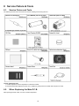
8 Service Fixture & Tools
8.1.
Service Fixture and Tools
The following Service Fixture and tools are used for checking and servicing this unit.
Leveller adjustment chart
1. Leveller adjustment chart for adjustment of electronic leveller.
2. Download the leveller adjustment chart "ACC_Adjustment_Chart.pdf" from the Web site and print in A3 size.
8.2.
When Replacing the Main P.C.B.
After replacing the Main P.C.B., be sure to achieve adjustment.
26
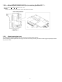
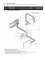
8.3.
Service Position
This Service Position is used for checking and replacing parts. Use the following Extension cables for servicing.
No.
1
2
3
Parts No.
VFK1906
VFK1541
VFK1906
8.3.1.
Connection
PP9006 (MAIN P.C.B.) - PS9201 (OPERATION P.C.B.)
PP9901 (TOP P.C.B.) - PS9002 (Main P.C.B.)
PP8001 (FLASH P.C.B.) - PS9903 (TOP P.C.B.)
Form
20PIN B to B
34PIN B to B
20PIN B to B
Extension Cable Connections
CAUTION-1. (When servicing Flash P.C.B.)
1. Be sure to discharge the capacitor on Flash P.C.B.
Refer to "HOW TO DISCHARGE THE CAPACITOR ON Flash P.C.B.".
The capacitor voltage is not lowered soon even if the AC Cord is unplugged or the battery is removed.
2. Be careful of the high voltage circuit on Flash P.C.B.
3. DO NOT allow other parts to touch the high voltage circuit on Flash P.C.B.
27
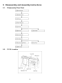
9 Disassembly and Assembly Instructions
9.1.
Disassembly Flow Chart
9.2.
P.C.B. Location
28
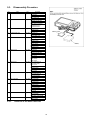
9.3.
Disassembly Procedure
No.
Item
1 Rear Case Unit
2
Operation P.C.B.
3
LCD Unit
4
Frame Plate Unit
5
Lens Unit
6
Main P.C.B.
7
NFC P.C.B.
8
Front Case Unit
9
Top Case Unit
10 Top P.C.B.
11 Flash Unit, Flash P.C.B.
12 Battery Case
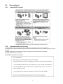
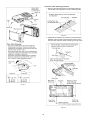
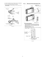
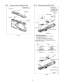
9.3.1.
Fig.
Removal
Fig. D1-1 4 screws (A)
1 screw (B)
4 Lockings tabs
Rear Case Unit
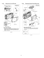
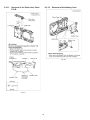
Fig. D2 FP9202 (Flex)
PP9006 (Connector)
Operation P.C.B.
Note:(When replacing
Operation P.C.B.)
Operation Sheet
Fig. D3 1 Locking tab
FP9003 (Flex)
LCD Unit
Fig. D4 3 screws (C)
4 Locking tabs
Frame Plate Unit
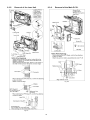
Fig. D5 2 Lockings tabs
PCB Spacer
FP9004 (Flex)
DPR Sheet (F)
2 FPC Tapes
FP9001 (Flex)
FP9005 (Flex)
Lens Unit
Fig. D6 1 screw (D)
1 Locking tab
PP9901 (Connector)
Jack Door
Main P.C.B.
Note: (When replacing
DPR Sheet)
DPR Sheet
Fig. D7 NFC Antenna Unit,
NFC Earth Plate,
NFC P.C.B.
1 screw (E)
FP9702 (Flex)
2 Locking tabs
NFC P.C.B.
Fig. D8 1 screw (F)
3 Lockings tabs (A)
1 Locking tab (B)
Front Case Unit
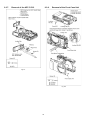
Fig. D9 5 Locking tabs
PP8001 (Connector)
Top Case Unit
Fig. D10 1 screw (G)
FP9902 (Flex)
2 Locking tabs (A)
2 Locking tab (B)
Earth Plate (R)
Top P.C.B.
Fig. D11 1 screw (H)
2 Locking tabs
Flash Unit, Flash P.C.B.
Fig. D12 2 Locking tabs
Battery Case
Removal of the Rear Case Unit
29
Protection sheet attaching procedure:
1. Remove the protection sheet from the base sheet and
fold the flap of the separator to the two-sided tape side.
Fig. D1-2
2. Slightly tilt the separator to prevent the two-sided tape's
adhesion. Align the flap of the separator with the end of
the rear case, and then attach according to the fig. below.
Fig. D1-1
Fig. D1-3
30
9.3.2.
3. Press the separator firmly and attach the two-sided tape.
4. Remove the separator slowly and carefully.
Check if there is nothing sticking out from the rear case
window frame.
Removal of the Operation P.C.B.
Fig. D1-4
Fig. D2
31
9.3.3.
Removal of the LCD Unit
9.3.4.
Removal of the Frame Plate Unit
Fig. D3
Fig. D4
32
9.3.5.
Removal of the Lens Unit
9.3.6.
Removal of the Main P.C.B.
Fig. D6
Fig. D5
33
9.3.7.
Removal of the NFC P.C.B.
9.3.8.
Removal of the Front Case Unit
Fig. D7
Fig. D8
34
9.3.9.
Removal of the Top Case Unit
9.3.10. Removal of the Top P.C.B.
Fig. D9
Fig. D10
35
9.3.11.
Removal of the Flash Unit, Flash
P.C.B.
9.3.12. Removal of the Battery Case
Fig. D12
Fig. D11
36
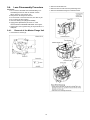
9.4.
Lens Disassembly Procedure
2. Remove the Shutter FPC.
3. Remove the Lens FPC from the positioning boss.
4. Remove the Master Flange Unit and Drive Gear.
Precaution:
1. Do not remove the MOS when disassembling or reassembling the lens in order to maintain it clean.
When remove it, refer to item "9.6".
2. Keep dust or dirt away from the lens.
3. To remove dirt or dust from the lens, blow with dry air.
4. Do not touch the lens surface.
5. Use lens cleaning KIT (BK)(VFK1900BK).
6. Apply grease (RFKZ0472) as shown on "THE
APPLICATION OF GREASE METHOD" in the figure.
7. Apply a light coat of grease using an object similar to a
toothpick.
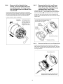
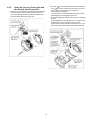
9.4.1.
Removal of the Master Flange Unit
1. Unscrew the 6 screws (A).
37
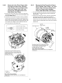
9.4.2.
Removal of the Drive Frame Unit,
Decorative Frame Unit, Outside
Cam Frame, 1st Lens Frame Unit,
2nd Lens Frame Unit, 3rd Lens
Frame Unit, Straight Frame and
Both Side Cam Frame
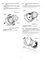
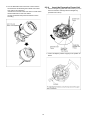
9.4.3.
Removal of the Decorative Frame
Unit, Outside Cam Frame, 1st Lens
Frame Unit, 2nd Lens Frame Unit,
3rd Lens Frame Unit, Straight
Frame and Both Side Cam Frame
1. Turn the Outside Cam Frame in the arrow (2) direction,
and then align the mark (Drive Frame and Outside
Cam Frame).
2. Push the 1st Lens Frame Unit in the arrow (2) direction
from the front of the Lens, and remove the Unit of
Decorative Frame Unit, Outside Cam Frame, 1st Lens
Frame Unit, 2nd Lens Frame Unit, 3rd Lens Frame Unit,
Straight Frame and Both Side Cam Frame from the Drive
Frame Unit.
1. Turn the Fix Cam Frame Unit in the arrow (1) direction,
and align the mark (Fix Cam Frame and Outside Cam
Frame and Drive Frame).
2. Push the 1st Lens Frame Unit in the arrow (2) direction
from the front of the Lens, and then remove the Unit of
Drive Frame Unit, Decorative Frame Unit, Outside Cam
Frame, 1st Lens Frame Unit, 2nd Lens Frame Unit, 3rd
Lens Frame Unit, Straight Frame and Both Side Cam
Frame from the Fix Cam Frame Unit.
38
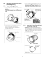
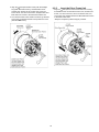
9.4.4.
Removal of the Outside Cam
Frame, 1st Lens Frame Unit, 2nd
Lens Frame Unit, 3rd Lens Frame
Unit, Straight Frame and Both Side
Cam Frame
9.4.5.
Removal of the 1st Lens Frame
Unit, 2nd Lens Frame Unit, 3rd
Lens Frame Unit, Straight Frame
and Both Side Cam Frame
• Hold the Both Side Cam Frame and turn it in the arrow
direction. Align the mark (Outside Cam Frame and Both
Side Cam Frame), and then remove the Unit of 1st Lens
Frame Unit, 2nd Lens Frame Unit, 3rd Lens Frame Unit,
Straight Frame and Both Side Cam Frame from the Outside
Cam Frame.
• Turn the Decorative Frame Unit in the arrow (1) direction,
and remove the Unit of Outside Cam Frame, 1st Lens Frame
Unit, 2nd Lens Frame Unit, 3rd Lens Frame Unit, Straight
Frame and Both Side Cam Frame from the Decorative
Frame Unit in the arrow (2) direction.
9.4.6.
Removal of the 1st Lens Frame Unit
• Turn the 1st Lens Frame Unit in the arrow (1) direction a
little, and remove the Unit of 2nd Lens Frame Unit, 3rd Lens
Frame Unit, Straight Frame and Both Side Cam Frame in the
arrow (2) direction.
39
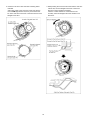
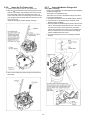
9.4.7.
Removal of the 2nd Lens Frame
Unit
9.4.8.
1. Hold the Straight Frame and turn it in the arrow (1) so that
the mark (2nd Lens Frame Unit) meets the mark
(Straight Frame).
2. Pushing the 3rd Lens Frame Unit in the arrow (2)
direction from the front of the Lens, turn it in the arrow (3)
direction.
Removal of the 3rd Lens Frame
Unit
• Push the 3rd Lens Frame Unit in the arrow direction from the
front of the Lens, and remove the 3rd Lens Frame Unit from
the Straight Frame and Both Side Cam Frame.
9.4.9.
Removal of the Straight Frame
• Turn the Straight Frame in the arrow direction, and align the
mark (Straight Frame and Both Side Cam Frame) in the
direction as below.
Align the Bayonet Key with the Bayonet Inlet, and remove
the Straight Frame from the Both Side Cam Frame.
40
9.5.
9.5.1.
Assembly Procedure for Lens
(Revised Version)
3. Turn the Straight Frame about 90 degrees in the arrow
direction so that the mark of Straight Frame comes
close to the mark of Both Side Cam Frame.
*As the drawing below indicates, align the Grooves of
Straight Frame with the one of Both Side Cam Frame.
Insert the Straight Frame
1. Insert the Straight Frame into the Both Side Cam Frame
as below.
(The phase difference between the two marks is about
90 degrees.)
*The mark of the Straight Frame is under the Shading
Sheet.
9.5.2.
2. Insert the Bayonet Key of the Straight Frame into the
Bayonet Inlet of the Both Side Cam Frame.
(Pass the convexity of Bayonet Inlet through the
concavity of Bayonet Key.)
Insert the 3rd Lens Frame Unit and
the 2nd Lens Frame Unit
1. Insert the 3rd Lens Frame Unit as the drawing below
indicated.
*Align the Stepping Motor of the 3rd Lens Frame Unit with
the mark of the Straight Frame Unit, then put the each
Cam Pin of the 3rd Lens Frame Unit in the each Groove
of the Straight Frame Unit.
41
3. While pushing the 3rd Lens Frame Unit and the 2nd Lens
Frame Unit, turn the Straight Frame Unit in the arrow
direction to the end.(about 30 degree)
*Need to confirm that the two Lens Frames move
smoothly when the Straight Frame Unit rotates in two
directions.
2. Insert the 2nd Lens Frame Unit as the drawing below
indicated.
*Align the mark of the 2nd Lens Frame Unit with the
one of the Straight Frame Unit, then put the each Cam
Pin of the 2nd Lens Frame Unit in the each Groove of the
Straight Frame Unit.
42
9.5.3.
Insert the 1st Lens Frame Unit and
the Outside Cam Frame Unit
2. Move the mark of the Both Side Cam Frame Unit closer
to the mark of the Outside Cam Frame Unit, then turn
the 1st Lens Frame Unit just a bit in the arrow
direction.(about 2 degrees)
*Hold the Cam Pin of the Both Side Frame Unit close to
the Straight Key of the Straight Frame Unit.
3. Insert the Straight Key and the Cam Pin into the following
grooves.
(1)The Straight Key of the Straight Unit -> The groove for
the Straight key of the Outside Cam Frame Unit
(2)The Cam Pin of the Both Side Cam Frame Unit -> The
groove for the Cam Pin of the Outside Cam Frame Unit
1. Insert the 1st Lens Frame as the drawing below indicated.
Pass the Cam Pin of the "LEICA" side of the 1st Lens
Frame Unit through the Area of Cam Pin Insertion near
the mark of Both Side Cam Frame Unit
43
9.5.4.
4. Turn the Both Side Cam Frame Unit to the end in the
arrow direction while holding the Outside Cam Frame
Unit. (About 118.5 degrees)
*Confirm that 1st Lens Frame Unit does not rotate when
the Both Side Cam Frame Unit rotates.
(It's the confirmation that previous insertion is done
normally.)
Insert the Decorative Frame Unit
1. Hold the Straight Key (Both Side Cam Frame), turn it in
the arrow direction and align with the Straight Key
(Outside Cam Frame).
2. Insert 2 toothpicks (rotation stopper) in the position as
below.
44
9.5.5.
3. Align the mark (Decorative Frame) with the Straight
Key (Both Side Cam Frame), and install the Unit of
Outside Cam Frame,1st Lens Frame Unit, 2nd Lens
Frame Unite, 3rd Lens Frame Unite, Straight Frame and
Both Side Cam Frame to the Decorative Frame Unit.
4. Turn the Decorative Frame Unite in the arrow (2) direction
so that the mark (Decorative Frame) meets the mark
(Outside Cam Frame).
Insert the Drive Frame Unit
• Align the mark (Drive Frame and Outside Cam Frame),
and install the Unit of Decorative Frame Unit, Outside Cam
Frame, 1st Lens Frame Unit, 2nd Lens Frame Unite, 3rd
Lens Frame Unit, Straight Frame and Both Side Cam Frame
to the Drive Frame Unit.
*Keep the toothpicks (rotation stopper ) inserted.
45
9.5.6.
Insert the Fix Frame Unit
9.5.7.
1. Install the Drive Gear to the Fix Cam Frame Unit.
2. Align the mark (Outside Cam Frame and Drive Frame
and Fix Cam Frame), and install the Unit of Drive Frame
Unit, Decorative Frame Unit, Outside Cam Frame, 1st
Lens Frame Unit, 2nd Lens Frame Unite, 3rd Lens Frame
Unit, Straight Frame and Both Side Cam Frame to the Fix
Cam Frame Unit.
*Keep the toothpicks (rotation stopper ) inserted.
Insert the Master Flange Unit
Note: (When Installing)
Refer to "The Application of Grease Method" when installing
the Master Flange Unit.
Take Care not to damage the flex.
Take Care not to tuck in to the Master Flange Unit, When
inserting the Shutter Flex.
1. Turn the Drive Frame Unit to the Wide position as below.
2. Push the Hole of the Shutter Flex to the Boss of the
Master Flange Unit tightly.
3. Place the Shutter Flex following the Guide of the Fix Cam
Frame, and install the Master Flange Unit to the Unit of
Fix Cam Frame Unite, Drive Frame Unit, Decorative
Frame Unit, Outside Cam Frame, 1st Lens Frame Unit,
2nd Lens Frame Unite, 3rd Lens Frame Unit, Straight
Frame and Both Side Cam Frame.
4. Turn the Drive Frame Unit to the completely retracted
position.
3. Remove the toothpicks (rotation stopper) and insert the
Drive Gear.
46
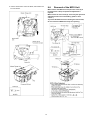
9.6.
5. Join the Zoom Motor Unit to the Boss, and install to the
Fix Cam Frame.
Removal of the MOS Unit
When remove the MOS Unit once (the Torx screw (A) is
loosened even a little), the optical tilt adjustment is
required.
When loosen the Torx screw (A), necessary the optical tilt
adjustment at the end of assembling. (Refer to item
"10.3.2.")
To prevent the MOS Unit from catching the dust and dirt,
do not remove the MOS Unit except for replacing.
47
10 Measurements and Adjustments
10.1. Introduction
When servicing this unit, make sure to perform the adjustments necessary based on the part(s) replaced.
When trouble occurs, it is recommended to backup the Flash-rom data before disassembling the unit.
NOTE: (When replacing the Lens unit, Master flange unit and MOS unit)
• When the MOS unit is unavoidably removed for Lens unit, Master flange unit and MOS unit replaced, an optical adjustment is
necessary after parts are exchanged.
• It is necessary to use the "DSC_Tilt" software to allow the "Optical tilt adjustment".
• The Adjustment software "DSC_Tilt" is available at "TSN Website".
NOTICE (When Main P.C.B. is exchanged)
Number of necessary adjustment items decreases by copying the backup data to new Main P.C.B. when adjustment data in old
Main P.C.B. can be read by ROM_BACKUP "DSC→SD" in "10.2.2. Flash-Rom Data Backup".
For more details, please refer an item "MAIN PCB (to which the backup data was copied)" in the table of "10.3.2. Adjustment
Specifications".
IMPORTANT NOTICE (After replacing the Main P.C.B.)
After replacing the Main P.C.B., it is necessary to achieve adjustment.
10.2. Before Disassembling the unit
10.2.1. Initial Setting Release
The cameras specification are initially set in accordance with model suffix (such as EB, EG, GK, GC, and so on.).
Unless the initial setting is not released, an automatic alignment software in the camera is not able to be executed when the
alignment is carried out.
Note:
The initial setting should be again done after completing the alignment. Otherwise, the camera may not work properly.
Therefore as a warning, the camera display a warning symbol " ! " on the LCD monitor every time the camera is turned off.
Refer to the procedure described in "3.4.2. INITIAL SETTINGS" for details.
[How to Release the camera initial setting]
Preparation:
Attach the Battery to the unit.
Set the recording mode dial to PROGRAM AE mode.
Step 1. Temporary cancellation of "INITIAL SETTINGS":
While pressing the UP of Cursor button and MOTION PICTURE button simultaneously, turn the Power on.
Step 2. Cancellation of "INITIAL SETTINGS":
Press the PLAYBACK button.
While pressing UP of Cursor button and MOTION PICTURE button simultaneously. (The camera will beep after this.)
Turn the Power off. (The warning symbol " ! " is displayed on the LCD monitor.)
48
10.2.2. Flash-Rom Data Backup
Number of necessary adjustment items decreases by copying the backup data to new Main P.C.B. when adjustment data in old
Main P.C.B. can be read by ROM_BACKUP "DSC→SD".
It is recommended to backup the Flash-rom data as the way of return when trouble occurs before disassembling the unit depending
on each case.
[ROM_BACKUP (Method of Non-PC backup)]
1. Insert the Memory Card into the camera.
2. Set the camera to "Temporary cancellation of the initial settings".
3. Select the "SETUP" menu.
From the "SETUP" menu, select "ROM BACKUP".
Note:
This item is not listed on the customer's "SET UP" menu.
4. When this "ROM_BACKUP" item is selected, the following submenus are displayed.
10.2.3. Light Box
If using VFK1164TDVLB Light Box, remove the lens connection
ring by loosing three hexagon screws.
49
10.3. Details of Electrical Adjustment
10.3.1. How to execute the Electrical Adjustment
It is not necessary to connect the camera to a PC to perform adjustments.
"Flag reset operation" and "Initial setting operation" are required when carrying out the alignment, follow the procedure below.
10.3.1.1. Startup Electrical Adjustment mode
1. Release the initial settings.
2. Insert a recordable Memory Card.
(Without a Memory Card, the automatic adjustment can
not executed.)
3. Procedure to set the camera into adjustment mode:
a. Set the mode into PROGRAM AE mode.
b. Turn the Power off.
c. Turn the Power on pressing MOTION PICTURE and
MENU/SET simultaneously.
LCD monitor displays "SERVICE MODE".
(Refer to Fig.F3-1)
Fig. 3-1
10.3.1.2. Status Adjustment Flag Setting
Reset (Not yet adjusted) the status flag condition.
1. After pressing the DISPLAY button, the LCD monitor
displays the Flag status screen (Refer to Fig.3-2.)
2. Select item by pressing the cross keys. (Gray cursor is
moved accordingly.)
3. Press the DELETE button.
Note:
The selected item's flag has been changed from
"F (green)" to "0 (yellow)".
*(Refer to Fig. 3-3)
*Flag conditions:
F (green)
means that the alignment has been completed and the
status flag condition is set. In this case, the flag condition
should be reset, if you try to carry out the automatic
alignment.
0 (yellow)
means that the alignment has been not "completed" and
the status flag condition is "reset". In this case, automatic
alignment is available.
Fig. 3-2
Fig. 3-3
• To display the "BKS" flag, choose the "RESET" and press the DOWN of Cursor button.
• In case of setting the status flag into set condition again without completion of the alignment, the status flag should be SET by
using PC, or UNDO by using ROM BACKUP function.
50
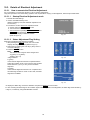
10.3.1.3. Execute Adjustment
1. Perform step "10.3.1.1." to "10.3.1.2.", to reset the OIS
flag status "F" (Set) to "0" (Reset).
2. Press DISPLAY button after Flag reset.
OIS Adjustment screen is displayed on the LCD panel.
(Refer to Fig.3-4)
3. Press the shutter button. The adjustment will start
automatically.
4. When the adjustment is completed successfully,
adjustment report menu appears with Green OK on the
LCD monitor. (Refer to Fig.3-5)
Fig. 3-4
Fig. 3-5
10.3.1.4. Attention point during Adjustment
1. Step "10.3.1.3." procedure shows OIS adjustment as an
example. To perform the adjustment, refer to the "10.3.2.
Adjustment Specifications" table which shows key point
for each adjustment.
2. Do not move the light box, the camera or the chart while
adjusting. If one of these is moved accidentally, start the
adjustment again.
3. Do not press any buttons/keys until the default menu
(Fig.3-6) is displayed on the LCD monitor. Otherwise,
adjustment data may not be stored properly.
4. If the adjustment is interrupted accidentally, the alignment
data may not be properly saved in the Flash-rom.
Fig. 3-6
10.3.1.5. Finalizing the Adjustment
1. Several adjustment flags can be reset ("F" into "0") at the same time. In this case, when the adjustment has been completed,
the screen will change showing the adjustment for the next item until all reset items are completed.
Also, when the shutter button is pressed, the screen jump to the next adjustment item.
2. To cancel the adjustment mode while in the process of performing the adjustment, follow this procedures.
(1) Press "Right of cross key" button.
Note:
*.If adjustment is cancelled with above procedure, adjustment is not completed. Make sure to adjust it later.
51
10.3.2. Adjustment Specifications
The following matrix table shows the relation between the replaced part and the Necessary Adjustment.
When a part is replaced, make sure to perform the necessary adjustment(s) in the order indicated.
The table below shows all the information necessary to perform each adjustment.
52
Q IMPORTANT NOTICE (After replacing the Main P.C.B.)
After replacing the Main P.C.B., make sure to perform the
"INITIAL SETTINGS" first, then release the "INITIAL
SETTINGS" in order to proceed the electrical adjustment.
Note:
1. If electrical adjustment or data re-writing is executed
before "INITIAL SETTINGS", suffix code list is never
displayed, and it cannot be chosen suitable suffix code.
2. Never remove the battery during initial setting in process.
53
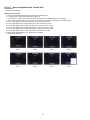
10.3.2.1. How to adjustment the Touch Panel
<Preparation>
• Prepare two touch pens.
<Adjustment Procedure>
1. Start up the automatic adjustment mode and set the TPC flag to "O".
2. (+) appears in the upper right and bottom left (Fig.3.7).
Touch the two (+) marks once at the same time. (At this time, (+) mark indications do not change.)
3. After 1 second or more elapses, touch the two (+) marks once at the same time again in the same manner.
4. The (+) mark appears in the center (Fig.3-8). Then touch the (+) mark.
5. The (+) mark appears in the upper left (Fig.3-9). Then touch the (+) mark.
6. The (+) mark appears in the bottom left (Fig.3-10). Then touch the (+) mark.
7. The (+) mark appears in the bottom right (Fig.3-11). Then touch the (+) mark.
8. The (+) mark appears in the upper right (Fig.3-12). Then touch the (+) mark.
9. The (+) mark appears in the center (Fig.3-13). Then touch the (+) mark.
10. When "OK" is displayed (Fig.3-14), adjustment is complete.
* Touch at least 500 msec.
54
10.3.2.2. How to Adjustment the Electronic Leveller
<Preparation>
• Download the leveller adjustment chart "ACC_Adjustment_Chart.pdf" from the Web site and print in A3 size.
• Fix the leveller adjustment chart to the wall or panel using thumbtacks and drop a thread with weight. (Fig.3-15)
Attach it to the wall or panel in that condition and remove the thread with weight.
• Attach the camera main unit to a tripod.
<Adjustment Procedure>
1. Place the camera main unit horizontally and keep the distance of 25 cm between the leveller adjustment chart and camera
main unit.
Set up the camera so that the optical axis of the lens intersects the center of the leveller adjustment chart at a right angle
(Fig.3-16)
1.1.) Adjust the height of the tripod so that the center of the leveller adjustment chart coincides with the height of the camera
lens.
1.2.) Put a triangle ruler at the center of the leveller adjustment chart, and then adjust so that the center of the camera lens
comes on the horizontal line.
1.3.) Adjust so that the leveller adjustment chart comes out on the full LCD screen.
1.4.) Make fine adjustment so that the side bar indication of the leveller adjustment chart appears horizontally on the LCD
screen and the cross shape guide indication of LCD of camera overlaps on the center. (Fig.3-17)
2. Press the shutter button.
→ "Green O" is displayed on the LCD. → Press the shutter button.
3. Rotate the camera at a 90-degree angle so that the grip faces upward with the camera attached to the tripod, and set up in the
same way as above 1). (Fig.3-18)
4. Press the shutter button.
→ "Green O" is displayed on the LCD. → Press the shutter button.
5. Rotate the camera at a 90-degree angle so that the grip faces downward with the camera attached to the tripod, and set up in
the same way as above 1). (Fig.3-19)
6. Press the shutter button.
→ "Green O" is displayed on the LCD. → Press the shutter button.
→ When "OK" is displayed, adjustment is complete.
55
10.4. After Adjustment
10.4.1. Initial Setting
Since the initial setting has been released to execute the built-in adjustment software, it should be set up again before shipping the
camera to the customer.
Refer to the procedure described in "3.4.2. INITIAL SETTINGS" for details.
[IMPORTANT]
1. The initial setting should be done again after completing the alignment. Otherwise, the camera will not work properly.
Therefore as a warning, the camera display a warning symbol " ! " on the LCD monitor every time the camera is turned off.
2. Confirm that status of all adjustment flag show "F". Even if one of the adjustment flag shows "0", initial setting programmed is
never executed.
56
11 Maintenance
11.1. Cleaning Lens, Viewfinder and LCD Panel
Do not touch the surface of lens, Viewfinder and LCD Panel with your hand.
When cleaning the lens, use air-Blower to blow off the dust.
When cleaning the LCD Panel, dampen the lens cleaning paper with lens cleaner, and the gently wipe the their surface.
Note:
The Lens Cleaning KIT; VFK1900BK(Only supplied as 10 set/Box) is available as Service Aid.
57
58
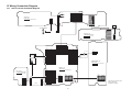
12 Block Diagram
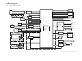
12.1. Overall Block Diagram
IC6005
FLASH ROM
/1Gbit
(24mm - 480mm)
IC3101
MOS
(DMC-TZ40/TZ41, ZS30P/PC/PU/GH/GT)
1/2.3" 18.9 MEGA PIX
IC9202
COMPASS
ZOOM
IRIS
SHUTTER
OIS UNIT
(27MHz)
FOCUS
NFC
ANTENNA
IC9101
MOTOR DRIVE,
OIS DRIVE &
PRE PROCESS
IC9201
ACCELATION
SENSOR
IC9701
NFC
SD
CARD
(DMC-TZ40/TZ41, ZS30P/PC/PU/GH/GT)
HDMI
TERMINAL
IC7201
1-axis GYRO
SENSOR
IC7101
2-axis GYRO
SENSOR
MICROPHONE (Lch)
IC8001
FLASH CONTROL
FLASH
(DMC-TZ40/TZ41, ZS30P/PC/PU/GH/GT)
GPS
ANTENNA
IC6501
GPC
IC6001
VENUS ENGINE, SDRAM
PRE/CAMERA PROCESS
J-PEG COMP/EXPAND
MEDIA I/F
USB I/F
MAIN MICROPROCESSOR
OIS CONTROL
MOS DRIVE
LENS DRIVE
LCD DRIVE
SDRAM/2Gbit
IC9101
VIDEO OUT &
AUDIO AMP
MICROPHONE (Rch)
MICROPHONE AMP
SPEAKER
SPEAKER CONTROL
DIGITAL/AV OUT
TERMINAL
IC9301
TOUCH PANEL
CONTROL
REAR OPERATION UNIT
TOUCH PANEL
COLOUR LCD
PANEL
3.0" PANEL
460K PIX
IC9101
SYSTEM IC
WiFi
ANTENNA
IC9501
WiFi
X9101
(32.768kHz)
IC1501
CHARGE IC
(Type of LCD Driver inclusion)
USB
TOP OPERATION UNIT
IC1001
POWER
BATTERY
(POWER SUPPLY)
DMC-TZ37/TZ40/TZ41/ZS27/ZS30 OVERALL BLOCK DIAGRAM
59
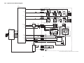
12.2. System Control Block Diagram
IC6001
(VENUS ENGINE)
OPERATION P.C.B.
PP9006 PS9201
6
6
CROSS KEY IN A15
D9105
PP9006 PS9201
8
8
WiFi SW IN AD22
D9102
RIGHT
DOWN
UP
S9203
S9202
S9201
2
1
2
1
2
1
2
1
2
1
4
3
4
3
4
3
4
3
4
3
PP9006 PS9201
7
7
PLAY N1
IC9101
POWER SW ON H
SHUTTER HALF
54
EXPOSURE
DELETE
DISPLAY
S9210
S9208
S9207
POWER ON L
PS9002
13
PS9002
15
PS9002
16
PS9002
9,10
SHUTTER 0
83
SHUTTER 1
SHUTTER 1 AC21
2
1
2
1
2
1
2
1
4
3
4
3
4
3
4
3
4
3
POWER SW
S9902
PP9901
13
PP9901
15
PP9901
16
PP9901
9,10
2
1
4
3
MOVIE
S9903
CL9932
2
1
4
3
MODE DIAL SW
(SYSTEM IC)
S9904
ZOOM & SHUT SW
S9901
IC9101
SHUT HALF
SHUT FULL
RESET OUT 85
S9206
1
CL9907
SYS RESET
MENU
2
CL9001
87
57
PLAY
S9205
TOP P.C.B.
(SYSTEM IC)
SHUT HALF N2
LEFT
S9204
PP9006 PS9201
5
5
REAR KEY IN C14
POWER SW ON G3
Wi-Fi
S9209
2
8
C2
9
C1
10
3D
8
11
SCN
M
7
12
S
6
3
iA
A
5
4
P
C
7
6
AA26 RSTB
CL9908
SCCS 67
T22 SYSCON CS
C
28 OSC IN
X9101
(32.768kHz)
1
SO 74
CL9903
AE22 SYSCON SI
26 OSC OUT
PS9002 PP9901
14
14
PS9002 PP9901
17
17
T W MOV B15
SCSI 71
AE21 SYSCON SO
MODE DIAL D14
AF22 SYSCON SCK
PS9002 PP9901
26
26
IC9001
(INVERTER)
GPS SO AD9
3
4
GPS SI AE9
6
1
TELE
LO
4
TELE
HI
C
1
MODE DIAL
CL9002
GPS ON H D3
3
5
T W MOV
CL9902
SCSCLK 70
2
WIDE WIDE
HI
LO
(DMC-TZ40/TZ41, ZS30P/PC/PU/GH/GT)
IC6501 (GPC)
22 ORCE-ON
CL6505
PS9002 PP9901
25
25
PS9002 PP9901
24
24
45 RXO
44 TXO
EINT 54
CL6504
GPC LED
D6502
IC9101
(SYSTEM IC)
CL9916
AF LED K
LEDOUT1 11
LEDOUT2 8
PW 3R4V
PS9002 PP9901
27
27
CL9917
PS9002 PP9901
5
5
AF ASSIST LED
D9901
BATT 27
BACKUP
PS9002 PP9901
21
21
B9901
TIMER BACK UP
BATTERY
DMC-TZ37/TZ40/TZ41/ZS27/ZS30 SYSTEM CONTROL BLOCK DIAGRAM
60
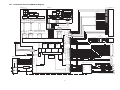
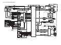
12.3. Audio/Video Process/ HDMI Block Diagram
IC6001
IC6005
(VENUS ENGINE, SDRAM)
(NAND FLASH/1Gbit)
LCD UNIT
BANK1
BANK2
BANK3
ROW
DECODER
COLUMN
DECODER
Y DECODERS
A9-A25
X-BUFFERS
LATCHES
& DECODERS
A0-A7
Y-BUFFERS
LATCHES
& DECODERS
NAND FLASH
ARRAY
TIMING & MODE REGISTER
LCDOUT1
LCDOUT2
I/O BUFFERS & LATCHES
LCDOUT3
LCDOUT4
CONTROL LOGIC
& HIGH VOLTAGE
GENERATOR
GLOBAL
BUFFERS
OUTPUT
DRIVER
LCDOUT5
LCDOUT6
8
9
I/O0
WPB
16 17
R/B
ALE
CLE
REB
18
CEB
LCDOUT7
WEB
BA0D
BA1D
CLKD
DQM0M
DQM1M
DQM2M
DQM3M
CSD
RASD
CASD
WED
CKED
DQS0
DQS1
DQS2
DQS3
DRA0M
DRD0M
Y-GATING
CTL SIG
DRA12M
ADDRESS
DRD31M
DATA
ADDRESS BUFFER & REGISTER
LCDOUT0
COMMAND
COMMAND
REGISTER
I/O BUFFER & GATE
PAGE REGISTER & S/A
LCDOUT8
I/O7
BANK0
X DECODERS
512Mbit(4Mx32bitx4pcs)
LCDOUT9
29-32,41-44
19 7
LCDOUT10
LCDOUT11
LCDOUT12
FRDT0-7
LCDOUT13
LCDOUT14
LCDOUT15
GPIO91
GPIO84
R1-R4,P1-P4
LCD VD D25
LCD HD D26
LCDOUT0
RAM DATA
(DRD0M-31M)
RAM ADDRESS
(DRA0M-12M)
FLASH DATA
(FRDT0M-7M)
RAM CONTROL
(CLK/CS etc.)
LCDOUT7
LCDOUT8
LCDOUT15
A22-A24,
B22-B23,
C22,C23,D22
B24,C25,D24,
E23-E26,F22
SYSCON SO AE21
S12C SCL H4
S12C SDA G1
PS9201
19
PS9201
20
PS9201
11
PS9201
12
25
7
JPEG
PROCESS
BLOCK
DR0
DR1
DR2
DR3
DR4
DR5
DR6
DR7
DG0
DG1
DG2
DG3
DG4
DG5
DG6
DG7
CS
SDATA
SCLK
TOUCH PANEL UNIT
24
5
15
6
22
4
FP9202
3
FP9202
1
FP9202
2
FP9202
4
XP
XN
YP
YN
JK2002
HDMI micro type-D
TP RESET U20
TPANEL IRQ H2
YC
PROCESS
BLOCK
HSYNC
IC9301
PP9006
19
PP9006
20
PP9006
11
PP9006
12
SYSCON SCK AF22
MOS UNIT
VSYNC
(CONTROLLER)
LCD CS AC18
SDATA AC17
SCLK AC19
MCU
DCLK
FP9003
50
FP9003
48
FP9003
49
LCD CLK C26
FR RB
FR WP
FR ALE
FR CLE
T1 U1 U2 U3 U4
FROM CS
T2
CPUREB
CPUWE2B
DRDQS0
DRDQS1
DRDQS2
DRDQS3
DRWEB
DRCKE
DRBA0
DRBA1
DRAM FCK
DRDQM0
DRDQM1
DRDQM2
DRDQM3
XDCS
DRRASB
DRCASB
DRA12M
DRD0
DRD31
DRA0M
T3
(Type of LCD Drive inclusion)
MAIN
FP9003
29
FP9003
26
FP9003
27
FP9003
30
FP9003
31
FP9003
32
FP9003
33
FP9003
34
FP9003
35
FP9003
36
FP9003
37
FP9003
38
FP9003
39
FP9003
40
FP9003
41
FP9003
42
FP9003
43
FP9003
44
FP9003
45
HDMI D2+
VIDEO
OUTPUT
BLOCK
HDMI D2FL2001
HDMI D1+
HDMI D1-
DAC
HDMI D0+
PRE
PROCESS
BLOCK
AC11-AC16,
AD11-AD16,
AE11-AE16,
AF11-AF16
IMAGE SIGNAL
HDMI TX2P A17
HDMI TX2M B17
HD
AE18
AF18
CMOSHD
MOS
SSG
C7 SDDAT0
C6 SDDAT1
D2 9
A5 SDDAT2
CARD
D3 1
DETECTION
CMD 2
B5 SDDAT3
A6 SDCLK
IC9101
6
WP
C
CD
WP
82 SDDET
IN
SDDET 51
OUT
HDMI D5V
JK2001
HDMI HPD D8
SW USB+ A12
SW USB- A11
USB
IF
IC1501 (USB SWITCH)
L2001
A2 DPO
A1 DMO
4
1
DP1 A4
DM1 A3
AV/USB TERMINAL
USB +
3
2
USB CABLE DET
CABLE DET F4
VIDEO OUT
IC9101
LINE OUT
(AUDIO CODEC/AUDIO&VIDEO OUT/SYSTEM IC)
SDC
VIDEO OUT M26
SYSCON CS T22
(SYSTEM IC)
C.DET
PW HDMI D5V
HDMI SDA C8
B6 SDCMD
CLK 5
HDMI HPDTC
HDMI SCL B7
P6401
(SD CARD CONNECTOR)
D1 8
HDMI SCL
HDMI SDA
HDMI CEC A7
EXT BUS
CONTROL
D0 7
HDMI CEC
HDMI TXCP A20
HDMI TXCM B20
CMOSVD
HDMI CK+
HDMI CK-
HDMI TX0P A19
HDMI TX0M B19
INTERNAL BUS CONTROL
VD
HDMI D0FL2002
HDMI TX1P A18
HDMI TX1M B18
C16 SDCDSYS
CLK27 SYS T26
A MCLK AD20
A DCLK AC20
A FCLK AF21
A DIN AE20
A DOUT AF20
D16 SDWP
63 VIDEO IN
67 SCCS
70
71
4
14
17
5
6
3
SCSCLK
SCSI
SYSCK
MCLK0
BCLK
LRCLK
ADOUT
DAIN
VIDEO OUT 61
LINEOUT 89
MICIN L 96
MICIN R 99
SPPOS 76
SPNEG 79
3
MAIN
TOP
PS9002 PP9901
20
20
PS9002 PP9901
18
18
TOP
FP9902
1
FP9902
2
PS9002 PP9901
19
19
FP9902
3
FP9902
4
MAIN
TOP
PS9002 PP9901
23
23
PS9002 PP9901
22
22
MICROPHONE UNIT
+
Lch
+
Rch
RL9911
RL9912
SPEAKER
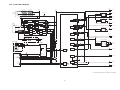
DMC-TZ37/TZ40/TZ41/ZS27/ZS30
AUDIO/VIDEO PROCESS BLOCK DAIGRAM
61
12.4. Lens Drive Block Diagram
FOCUS ENC
FP9005
10
11
FHP LED
FZHP ABS
NFC P.C.B.
IC9701
IC6001
IC7101
(VENUS ENGINE)
(2-axis GYRO SENSOR)
W24 G FHP
(RF ID)
FP9004 FT9651 FT9652 FP9701
5
5
6
6
14 IRQ3V
VB 2
NFC
ANTENNA
9 SCLK
GYRO SCK Y24
CD BARREL ENC
VA 7
GYRO DI AA25
10 MISO
GYRO DO AA24
11 MOSI
W25 G ZHP
ZOOM ENC
5
8
6
9
ZENC1 LED
(DMC-TZ40/TZ41,
ZS30P/PC/PU/GH/GT)
ZENC2 LED
ZENC1 ABS
IC7201
W23 ZENC1
ZENC2 ABS
Y26 ZENC2
ZENC LED
(1-axis GYRO SENSOR)
SNFC IRQ IN Y2
FZHP LED
IC9101
FP9004 FT9651 FT9652 FP9701
9
9
3
3
G GYRO AD P26
(LENS MOTOR DRIVE/SYSTEM IC)
CMOS
FILTER
FP9005
M
15,16
19,20
FOCUS MOTOR
(STEPPING)
17,18
13,14
M
23,24
21,22
IRIS MOTOR
(STEPPING)
27,28
25,26
M
29
SHUTTER MOTOR
(SOLENOID)
31
30
32
M
3
FMBP
FMBN
FMAP
FMAN
IRISBP
IRISBN
IRISAP
IRISAN
1
12
PIOUT1
PIOUT2
19
AMP(B ch)
16
13
38
AMP(A ch)
18
DAC
21
1
AMP(C ch)
42
43
46
2
AMP(D ch)
120
44
SHUTP
SHUTN
DCM+
DCM-
PWMA
PWMB
PWM IRIS A
PWM IRIS B
SHUTTER A
SHUTTER B
2
V24 PWM FB
C2
9
10
3D
U23 PWM IRIS A
C1
8
11
SCN
M
7
12
S
6
3
iA
A
5
4
P
DRIVER
DAC
LOGIC
50
4
V26 PWM IRIS B
R23 SHUTTER A
T25 SHUTTER B
40
DRIVER
56
SYSCK
37
39
42
40
YVYHO+
1
LZCK
LZDI
LZLD
U26 DAC CK
T23 DAC DI
PS9002 PP9901
17
17
MODE DIAL D14
T24 DAC LD
CL9903
ZOOM & SHUT SW
PS9002 PP9901
14
14
T W MOV B15
WIDE WIDE
HI
LO
DAC
47
HALL
SENSOR
C
T26 CLK27 SYS
CL9902
41
58
LENS UNIT
HALL
SENSOR
C
52
AMP(X/Y ch)
FP9005
XDR34
XDR+
33
XHO+
37
XHO35
XV+
36
XV38
YDR43
YDR+
44
YV+
41
MODE DIAL SW
S9904
V25 PWM FA
2
OIS UNIT
2 OUT
TOP P.C.B.
22
4
ZOOM MOTOR
(DC)
9
XPWM
1
U25 PWM XOIS
2
S9901
TELE TELE
LO
HI
5
3
4
C
ADC
XMN
XMP
48
66
69
YPWM
CL9907
U24 PWM YOIS
AMP(X ch)
SHUTTER 1 AC21
YMN
YMP
XINP
XHN
YHO-
72
75
112
111
SHUT HALF
PS9002 PP9901
15
15
PS9002 PP9901
16
16
8
SHUT FULL
7
6
CL9908
IC9101
(SYSTEM IC)
AMP(Y ch)
SHUT HALF
57
SHUT HALF N2
AMP
(XH)
FLASH P.C.B.
SHUTTER 0
83
CL8001
CC8026
T8001
YINP
YHN
XVP
YVP
104
105
110
107
BAT+
AMP
(YH)
P8002
1
F8002
F8001
3
2
5
1
C8003
(For Flash
Charge
AMP
(XV)
(FLASH CONTROL)
CL8020
PWM IN
(DMC-TZ40/TZ41,
ZS30P/PC/PU/GH/GT)
IC9202
STB CHG START E2
OPERATION P.C.B.
86
PWM OUT
MAIN
TOP
PS9002 PP9901
4
4
TOP
PS9903 PP8001
10
10
MAIN
TOP
PS9002 PP9901
2
2
TOP
PS9903 PP8001
8
8
VC 4
2
1
CL8022
6 START
3 T8002
2
SCL 3
SDA 5
DRDY 1
RSTN 10
IC9201
(ACCELATION SENSOR)
SD1 6
81
FLASH
10
SW
CL8009
(COMPASS)
SCL 4
1
IC8001
AMP
(YV)
PW D +5V
D9201
WiFi LED
PS9201
19
PS9201
20
PS9201
2
PS9201
4
PS9201
18
PS9201
17
PS9201
15
MAIN
PP9006
19
PP9006
20
PP9006
2
PP9006
4
PP9006
18
PP9006
17
PP9006
15
STB CHG DET R24
H4 S 12C SCL
CL8023
9 FULL
G1 S 12C SDA
Q8001
R22 COM IRQ
CL8005
W26 COM RSTN
7
6
5
1
2
3
CL8004
IGBT OUT 2
K3 ACCEL IRQ1
K4 ACCEL IRQ2
8
STROBE TRG AA4
MAIN
TOP
PS9002 PP9901
3
3
TOP
PS9903 PP8001
9
9
4
7 IGBT IN
T20 WiFi LED
INT1 11
INT2 9
DMC-TZ37/TZ40/TZ41/ZS27/ZS30 LENS DRIVE BLOCK DIAGRAM
62
12.5. Power Block Diagram
CL1010
CL9003
F8002
FLASH TOP
PP8001 PS9903
1-5
1-5
TOP
MAIN
PP9901 PS9002
37-40 37-40
PP8001 PS9903
13-20 13-20
PP9901 PS9002
32,33 32,33
CL1001
PW +5.2V
IC1021 (REGULATOR)
IC1001
BATTERY
TERMINAL
FLASH TOP
PP8001 PS9903
7
7
BAT THERMO
(SWITCHING REGULATOR)
PW HDMI D+5V
G
TOP
MAIN
PP9901 PS9002
1
1
4 VIN
VOUT 1
3 CE
VSS 2
CL1021
PW A +3.1V
CL1020
D
S
PW +3.4V
Q1501
CL1503
IC1022 (REGULATOR)
LX1
IC1501
(USB SWITCHING CHARGER)
VO1E
CH1
VBAT
E6
VBAT
F6
PGND1
42
4 VIN
VOUT 1
3 CE
VSS 2
PW SD +3V
41
39
SYSTEM
E5
SYSTEM
F5
CC-CV
CONTROL
CL1022
CL1009
SD +3V CTL
JK2001
AV/USB
TERMINAL
F4
F2002
USB CAB IN
TH
THERMO
VBUS
A5
VBUS
A6
CL2005
USB -
LX
C5
LX
C6
PGND
8
PGND
9
DRIVER
CONTROL
LOGIC
3
4
A4
2
1
A3
USB OK
F2
CRG
VO2E
LX21
LX22
PGND2
B3
CL1080
38
PW D +3.0V
35
37
36
IC1023 (REGULATOR)
USB CHG
DETECTOR
SWITCH
LED
DRIVER
12C I/F
XPWER ON
E2
LX3
SDA
D2
SCL
D1
HX36
CH3
PGND3
CL1023
34
CL1502
DP
DM
HX2
CH2
UVLO/
SWITCH
L2001
USB +
28V
OVP
PWM
DC/DC
4 VIN
VOUT 1
3 CE
VSS 2
PW SE +2.8V
30
32
28
CL1030
OPERATION P.C.B.
LX4
PP9006 PS9201
16
16
PS9201 PP9006
13
13
CH4
USB VBS
HX4
26
27
CHG LED
D9201
IC1040
TOP P.C.B.
8 CE1
CL9001
POWER SW
S9902
2
IC9101
(SYSTEM IC)
LX5
CH5
PP9901 PS9002
13
13
PP9901 PS9002
9,10
9,10
87 POWER ON L
HX5
PGND45
24
GND 1
CL1042
7 VDD1
VOUT1 2
PW SE +1.8V
VOUT2 3
PW D +1.8V
5 CE2
25
(REGULATOR)
6 VDD2
23
GND 4
CL1041
1
OVERCUT 33
CL1050
CL1003
4
PW D +1.1V
CL1040
LDO
3
9
POWER CTL SW 35
STB1234
REGOUT
19
PW SEN +1.2V
ON/OFF
LOGIC
EV3 23
IC6001
(VENUS ENGINE)
CL6011
POWER SW ON G3
54 POWER SW ON H
CL1060
84 POWER ON H
POWER ON H U22
CH6
LX6
22
PW DRM +1.22V
D9103
XPW ON K1
BATT THERMO V D13
SW UNREG C13
PGND67
21
CL1070
CL1005
CL1004
CH7
S IIC SCL L2
8
S IIC SDA H2
7
LX7
D1070
20
PW BL PLUS
SCL
SDA
SERIAL
INTERFACE
VO7
14
SW OUT 40
CL1011
PW HDMI +5V
DMC-TZ37/TZ40/TZ41/ZS27/ZS30 POWER BLOCK DIAGRAM
63
13 Wiring Connection Diagram
21
22
23
24
25
26
27
28
29
30
31
32
33
34
35
36
37
38
39
40
13.1. Interconnection Schematic Diagram
STB_CHG_OUT
STROBE_TRG
STB_CHG_DET
BAT_THERMO
NC
BAT+
BAT+
BAT+
BAT+
BAT+
STB_GND
PW_3R4V
BATBATBATBATBATBATBATBAT-
PS9903
: (COMPONENT SIDE)
11
12
13
14
15
16
17
18
19
20
FP9902
1 MIC_L
2 MIC_GND_L
3 MIC_R
4 MIC_GND_R
TOP P.C.B.
(FOIL SIDE)
PP9901
20 MIC_LIN
19 MIC_RIN
18 MIC_GND
17 MODE_DIAL
16 SHUTTER_1
15 SHUTTER_0
14 T_W_MOV
13 POWER_ON_L
12 PW_GPS_3R1V
11 PW_D3V
10 D_GND
9 D_GND
8 WF_CMD
7 SLK24_WFCLK
6 STB_GND
5 PW_3R4V
4 STB_CHG_OUT
3 STROBE_TRG
2 STB_CHG_DET
1 BATT_THERMO
RL9912
10
9
8
7
6
5
4
3
2
1
BACKUP
SPSP+
S_GPS_SI
S_GPS_SO
GPS_ON_H
AF_LED_K
BUS24_WDAT3
BUS24_WDAT2
BUS24_WDAT1
BUS24_WDAT0
D_GND
D_GND
(WIFI_INT_B)
PAD_EN
WIFI_RESET
BATT+
BATT+
BATT+
BATT+
RL9911
BATTERY
STB_PWM_OUT
STROBE_TRG
STB_CHG_DET
BAT_THERMO
NC
BAT+
BAT+
BAT+
BAT+
BAT+
10
9
8
7
6
5
4
3
2
1
MICROPHONE
SPEAKER
MOS
UNIT
LENS
UNIT
GND
AVDD28
GND
DVDD12
GND
GND
DVDD18
RSTN
MCLK
SCK
CS
HD
SENSOR_THERMO
GND
GND
DOBM
DOAM
DOCM
DOEM
DCKM
DOFM
DOHM
DOJM
DOIM
GND
2
4
6
8
10
12
14
16
18
20
22
24
26
28
30
32
34
36
38
40
42
44
46
48
50
PS9002
1 BATT_THERMO
2 STB_CHG_DET
3 STROBE_TRG
4 STB_CHG_OUT
5 PW_3R4V
6 STB_GND
7 CLK24_ECLK
8 WCMD
9 D_GND
10 D_GND
11 PW_D3V
12 PW_GPS_3R1V
13 POWER_ON_L
14 T_W_MOV
15 SHUTTER_0
16 SHUTTER_1
17 MODE_DIAL
18 MIC_GND
19 MIC_RIN
20 MIC_LIN
FP9001
1 GND
3 AVDD28
5 GND
7 GND
9 DVDD12
11 GND
13 DVDD18
15 GND
17 GND
19 GND
21 SDATA
23 VD
25 GND
27 GND
29 GND
31 DOBP
33 DOAP
35 DOCP
37 DOEP
39 DCKP
41 DOFP
43 DOHP
45 DOJP
47 DOIP
49 GND
51 GND
BATT+
BATT+
BATT+
BATT+
WIFI_RESET
PAD_EN
NC
D_GND
D_GND
BUS24_WDAT0
BUS24_WDAT1
BUS24_WDAT2
BUS24_WDAT3
AF_LED_K
GPS_ON_H
S_GPS_SO
S_GPS_SI
SP+
SPBACKUP
40
39
38
37
36
35
34
33
32
31
30
29
28
27
26
25
24
23
22
21
: (FOIL SIDE)
P8002
BAT+
BAT_THERMO
BAT-
PP8001
11 STB_GND
12 PW_3R4V
13 BAT14 BAT15 BAT16 BAT17 BAT18 BAT19 BAT20 BAT-
1
2
3
FLASH P.C.B.
(CONPONENT SIDE)
FP9003
50
48
46
44
42
40
38
36
34
32
30
28
26
24
22
20
18
16
14
12
10
8
6
4
2
GND
SCL
VDDIO
DG7
DG5
DG3
DG1
DR7
DR5
DR3
DR1
DCLK
HSYNC
VCC
VSSA
SP2
SP1
VDDA
C2P
C3P
C4M
VDD
C1AM
C1BP
VGL
VLED+
CS
SDA
VPPMTF
DG6
DG4
DG2
DG0
DR6
DR4
DR2
DR0
DE
VSYNC
VINT2
VCOM
DRV
VINT1
C2M
C3M
VGH
C4P
VCL
C1AP
C1BP
VLED-
51
49
47
45
43
41
39
37
35
33
31
29
27
25
23
21
19
17
15
13
11
9
7
5
3
1
FP9202
(TOUCH PANEL)
1
2
3
4
XN
YP
XP
YN
LCD UNIT
OPERATION P.C.B.
(FOIL SIDE)
: (COMPONENT SIDE)
MAIN P.C.B.
(FOIL SIDE)
NFC P.C.B.
(CONPONENT SIDE)
: (FOIL SIDE)
FP9701
NC
11
RFID_SCLK 10
GND
9
RFID_SIO
8
PW_NFC_3R1V 7
6
RFID_IRQ
GYRO_GND 5
4
GYRO_REF
3
GYRO_AD
2
PW_A3R1V
1
NC
FT9652
11
10
9
8
7
6
5
4
3
2
1
JOINT FPC
FT9651
1
2
3
4
5
6
7
8
9
10
FP9005
1 ZM3 ZM+
5 ZENC1_LED
7 ZENC_VCC
9 ZENC2_ABS
11 FZHP_ABS
13 FA15 FB+
17 FA+
19 FB21 IRB23 IRB+
25 IRA27 IRA+
29 SH+
31 SH33 XDR+
35 XHO37 XHO+
39 YHI41 YHI+
43 YDR45 FRAME_GND
NMZM+
ZENC1_ABS
ZENC2_LED
FZHP_LED
FZHP_VCC
FAFB+
FA+
FBIRBIRB+
IRAIRA+
SH+
SHXDRXHI+
XHIYHOYHO+
YDR+
2
4
6
8
10
12
14
16
18
20
22
24
26
28
30
32
34
36
38
40
42
44
: (COMPONENT SIDE)
FP9004
1 RFID_SCLK
2 GND
3 RFID_SIO
4 PW_NFC_3R1V
5 RFID_IRQ
6 GYRO_GND
7 GYRO_GND
8 GYRO_REF
9 GYRO_AD
10 PW_A3R1V
PP9006
10 GND
9 GND
8 WIFI_SW
7 PLAY_SW
6 CROSS_KEYIN
5 REAR_KEYIN
4 COM_RSTN
3 COM_TRI
2 COM_IRQ
1 PW_D3V
TP_RESET
TPANEL_IRQ
USB_VBUS
PW_D5V
WIFILED
CTD_CHGLED
ACCEL_IRQ2
ACCEL_IRQ1
S_I2C_SCL
S_I2C_SDA
11
12
13
14
15
16
17
18
19
20
PS9201
10 GND
9 GND
8 WIFI_SW
7 PLAY_SW
6 CROSS_KEYIN
5 REAR_KEYIN
4 COM_RSTN
3 COM_TRI
2 COM_IRQ
1 PW_D3V
TP_RESET
TPANEL_IRQ
USB_VBUS
PW_D5V
WIFILED
CTD_CHGLED
ACCEL_IRQ2
ACCEL_IRQ1
S_I2C_SCL
S_I2C_SDA
11
12
13
14
15
16
17
18
19
20
DMC-TZ37/TZ40/TZ41/ZS27/ZS30
INTERCONNECTION
SCHEMATIC DIAGRAM
64