1
Built in Europe for
the needs of the
American user.
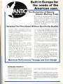
The Economics of Owning
Atlantic Machine Tools
Wi'h inflation a world-wide problem, Atlantic's
policy of having high quality machines built
devoid of what IS not required 10 produce parts
accurately and efficiently is now paying
dividends to budget conscious shops around
North America, The Items below are meant to
reinforce our philosophy.
Keeping The Price Down Without Sacrificing Quality
• All Steel Welded construe ion mak s the
machines V1ftually indes ructible, If an overload
develops the steel can give instead a p rmanen·
Iy deforming or breaking,
• The Hyd aulic systems prOVide instant control at
the machine for safety along With pressure relief
systems to prevent overloads and subsequent
ha rm to the m chine, All components with Ih ex·
ception of the cylinders are purchased Hems
keeping the cost down and making r placement
parts available on a local baSIS.
• ElectrIC controls can be a common source of
machine downtime, We cllose to use Allen
Bradley electrics for heir world renowned quality
and availabil'ty almost anywhere locally
Atlantic press brakes (up to 250 ton) utilize a lor·
sion bar to keep the ram parallel thereby
eliminating a complicated and expensive
hydraUlic propor ionlng system. Th
unique
hydraulic system allows the ram 0 "'ree all" In
the rapid mode reduc'ng the need for high flow
pumps and the resultant large motor and electric
requirements This results in conSIderable energy
reduction reqUirements for you,
• In our shear we use replaceable hardened ways
Nilh the upper blade ram guided on roller bear
mgs. This gives the user the ability to easily
eplace these when they eventually wear out, and
us t e economic advantage of not having to be as
precise when mac~lining the components before
assemb y In our press brakes the use of non
m taille glbs provide the same benefits.
• The machines are finished in an epoxy-based
rough lex ure paint eliminating the hours of filling
and finishing needed if we were to use a glossy
finish.
• The elimination of a gap In our shears and the use
of pull down cylinders enable us to localize the
stresses eliminating the massive side frames reo
Quired in overdrlven machines,
• All AtlantiC mactllnes use the hydraulic tank as an
Integral structure of the machine further reducing
cos s of additional components.
• Factory tramed service personnel not only pro
vide service if a problem arises with your
machine but also do 1Ile original installation to in·
sure illat your staf understands the maintenance
and opera Ion of the equipment.
Maximum Performance Through Low Cost Design
EXPRESSED WARRANTY
All AtlantiC Machine Tools are warra ted 10 be free rom
detects lor a period of one full year from date of Installa'ion
by our serV1CemBf1 ThiS Includes all ports ane labor except
shear blades, dies and tooling, Warranty will be considered
VOid if machine is not used in a normal and p oper ma nero
not properly maintained, or modified tor any speCial use
No otrer warranty is either expressed or Implied by Atlan·
tiC Machine Tools or any at ItS representatives.
For the sake of expediency InVOlVIng a minor ia Ilure, AI an·
tic Machine Tools may at I\S option allow the user to pur
chase a needed part locally for whic he will be reimburs
ed upon receip of the detective part at Columbus, Ohio
SAFETY-All Atlantic Machine Tools are buill to conform
to American Slandard Institute BII 4 1973 Safety Stan·
dards, However, due 10 the multi purpose use of some of
the eqUipment the p rchaser shall be responsible for the
proper instailallon and continued use of pain! of operation
guards or awareness barriers to assure co plete operalOr
safety.
HYDRAULIC
PRESS BRAKES
80 ton x 6'
to
1000 ton x 20'
ALL·STEEL WELDED
CONSTRUCTION
•
---------------------
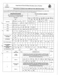
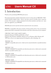
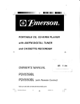
TONS PRESSU RE
THICKNESS
WIDTH OF FEMALE
OF METAL
F~o c.
Dec.
'/4" 5/16 "
20
18
16
0.036
0.0'18
0.060
2.6
14
13
12
0.075
0.090
0.105
Go.
11
\0
9
2.2
3.5
3/1~"
1" 1 1
/a" 1 1k
W' 1f2"
5/S"
%"
7/S"
1.2
2.1
3.7
1.0
1.7
2.6
1.3
2.2
1.7
5.5
4.6
6.4
9.2
3.5
5.5
6.9
3.0
4.3
6.2
2.5
3.6
5.0
2.1
3.2
4.3
2.6
3.9
3.1
6.0
10.3
7.0
6.7
11.9
6.1
7.8
9.8
5.3
6.9
8.8
4.3
5.7
7.0
1.6
2.8
5.3
0.120
0.135
0.150
7
required per lineal foot to bend mild steel
10.1
0.188
0.250
0.313
'I."
>/I~"
%"
11fi
1 3.9 11.2
2.7.5 21.1
39.2
16.9
'/,~"
'11"
;/e"
'Ie"
I"
2.9
3.9
5.0
3" 13112'
4"
5"
6.7
10.4
7.7
6"
7"
8" 10" 12"
9.6
15.0
19.5
11.5
16.1
13.4
27.3
43.2
23.3
36.2
3.7
6.7
4.9
8.3
15.0 11.6
9.6
26.5 19.3 15.0
7.9
12.5
31.2 23.8 19.5 16.3 12.4
45.5 35.2 28.5 24.4 17.4
48.5 39.5 33.2 24.6
65.5
0.625
0.750
0.875
1.000
3/.'
2" 2 112'
42.7
0.375
0.438
0.500
DIE OPENING
57.9 42.8 33.1
92.3 66.1 S3.0
103.1 79.9
112.1
17.0
26.9
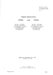
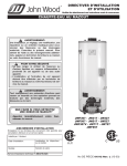
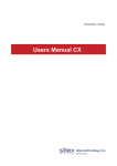
SPECIFICATIONS
/
/
an
HD60 10 R
HD60 I~ '0
HDIOO6·~
110111("; 8
'00
I
,
HOI~(!t,4' 1(1
1tr>11)~ '08
"01 , 12 III
~i01{i!J
~
J /
HD811(1 °1
H0100 '08
110100·'2·10
HOIYJ (i ~
HDI35,'O·8
\h
\01.1
li'l'
/2
02
,. "
7.:
1~4
I""
72
o~
l;>u
1·1,1
I?:'
1?'O
14·:
1/.1
rlO1'00-10 t\
HOlOO 12 10
HO'OO 14 I?
'20
tcO;1',O to 6
toll;:)50 ~ 10
tiO?50
HOJOU
110100
11DJOIJ
1<'0
2,,0
I. I?
,
10 B
I
"
I?
;1011
~[)3DO I. "
'10">(, 1061
IIO,~I.t\
I:> 1O
HO:,:'> 14 1
.-10·::.0 lC, 14
~OIA
\~.1
'r>6
-150
ou
I.
1:"11'
,."
"
98
....
,~
I
I·:':
;16
1 ;'J~.
16
t£i?
I';'~,
~!; c~
Q5
I""
168
I
14{;
I
,
.','
I
~.
"
;
R~
~, 1~
9 7~
,
10
~
HI)
If
I H If
7~
7~1
I'
?11
I',
",~
180
'h~
h~
\
1>11
"
1~
II
,ql
'''.'.
I~
.:'
d"
8-'
....
90
7"
!lO
In
l':;~
, 'I.9.
1f',
II'
1':',
llb
IUl
."
I"
11)
'1 ~
~I~
1'>0
I
n
1 'I
r~
dO
"
Ilf.
"It.,
1;1J
PO J
2111
;~~
10J
I •.
III
1:'
I ,:~
110
110
I.?.?
1.1/
lolL
,X".J
170
Ilj?
12<'
1116
\.:~
1'0
PM
,I [2
l1e
l,g
1:56
"
'" 000
9!>OO
I
" 000
'"000
"000
bO
.,
ti.
103
,
t
8000
1('000
'>0
'.:G
'00
l~i.
.1<
"
'u
/
.~/~~
/rll
B
.'
I[,()
.' I ..'
;.:
/
.t~.o/ ¥
... ~...
•'1.
110
1,'(1
)
.1/
.
I""
9U
,,'.11
1
J"
R
l':ll
IfiB
24Q
,'/
oa
"'01
:"/ IT
I,:"
"8
Hofl
20IJ
~ ....
~f
/7
1('11
t~)
1"
I~
,~
/ 1/ j'~~&
~~;/,t$
.00"
/
\jOOO
\8
21000
23000
1• 000
'<0000
'"
oS
14000
2uOOO
I.~
32000
n
2',1000
000
1<
7·'
7~
2"
"
J'IOOJ
<lao:.
137 000
,~oo
JO
;
p'
,t.:.
">:!OCWl
14 '
110
'94
,to
00.'
6100u
)~)
'lIl
J'
.;2
''''
000
~
F~
Press Brake-rear view
80000
STANDARD EQUIPMENT
All Steel Construction
Allen Bradley Electrics
Power Stroke Adjustment
Portable Foot Control
Hydraulic Fluid
Infinite Pressure Adjustment
21.0
63.9 52.3 39.2 31.2
90.4 7S.5 55.7 43.7
Inch Control
Rapid Advance Speed, Slow Pressing Speed
and Rapid Return
Mechanical Stops in Cylinders.
Machines wired for 220/440V, 3 phase
operation (Specify voltage needed,)
HYDRAULIC
PRESS BRAKES
STANDARD EQUIPMENT
TORSION BAR SIMPLICITY
All machines thru 250 ton 12 ft. utilize a
steel torsion bar to maintain ram parallelism
until the cylinders stops are engaged. This
design eliminates complicated and many
times troublesome Hydraulic proportioning
valves, steel tapes and micro switches
associated with so many hydraulic press
brakes.
ENERGY SAVING DESIGN
Due to the unique hydraulic circuit design
Atlanllc Press Brakes operate with consid
erably less H.P. requirements than most
comparable machines, thereby saving up to
25% on electric usage.
POSITIVE CYLINDER STOPS
NON METALLIC GIBS
All machines have positive adjustable stops
bUilt Into the hydraulic cylinders. These
stops provide accurate repetition of deRth of
stroke regardless 01 tonnage being used.
Thus providing bending accuracy limited
only to the variables of the material itself.
Please note that while the need for accurate
depth control is recognized for air bending,
the same condition exists for bottoming
dies, Since If set too low they will over bend
the same as air bend dies.
The use 01 adjustable non-metallic gibs pre
vents galling ot ihe bearing surfaces and
permits minimum running clearances lor
accurate ram guidance,
l
RAPIO
""9 F\OA.C H
PFl:bSINO
~~EEO
'
;..o.Ulltaf;Jl.
R~Or,)
10' Tf+(! ConllQll
PGown Stlo... ~ ACIIJ.lI~"'t C04'IttOl.l
MULTI SPEED OPERATION
SIMPLE UNITIZED
CONTROLS
All operators controls for set up and opera
tion are located together for ease of opera
tion. Within the control box Allen Bradley
components are used exclusively for relia
bility.
Multi Speed operation is featured on all
Aliantic press brakes
• Rapid advance to workpiece-adjustable
at control box
• Slow press thru work-until ram bottoms
on cylinder stops
• Rapid return-to adjustable up position
The complete adjustment of stroke length,
depth and tonnage makes Atlantic brakes
compatible with any bending requirements
you may encounter.
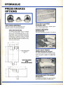
PRESS BRAKES
OPTIONS
TWO HAND CONTROLS
BOLT ON T SLOTTED
SUPPORT BAR
With anti tie down are recommended when
using the machine for punching purposes,
Can be ordered with either T slot1ed support
arms or solid support arms.
CNC BACKGUAGES
All Atlantic press brakes may be ordered
with a CNC Backgauge syslem. A CNC
Backgauge will automatically position after
each press stroke dramatically Increasing
productivity by reducing material handling
time necessary with manual gauging, It also
offers the added benefits of reduced scrap
and more uniform parts.
POWER OPERATED
BACKGAUGE
Will speed backgauge positions if so desired.
"A"
'/z-13NC SETSCREWS
12" CENTERS
TYP,
HEAVY DUTY FRONT
OPERATED BACK GAUGE
The highly adjustable back gauge is posi
tioned with acme screws and adjustable
nuts to provide a lifetime of trouble free
service.
DIE HOLDERS
AN'D
FILLER BLOCKS
--1'~
A,'
II--=r~=I
!be-=--=
in
I
.1~1i..'~
~
MACHINED BED FOR ANGLE
BRACKETS
Is available to facilitate the use of unitized
punching tooling (factory installed only).
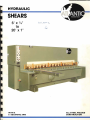
HYDRAUI.IC
SHEARS
6'
X 1/4 "
to
20' x 1"
WITHA
6' SQUARING ARM
ALL-STEEL WEL-DED
CONSTRUCTION
SHEARS
STANDARD EQUIPMENT
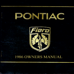
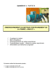
SPECIFICATIONS
STANDARD EQUIPMENT
H07-6
H07-8
HD7-10
HD7·12
HD25·6
HD25·8
H025·10
H025-12
H038-5
HD38-S
HD38-10
HD38-12
HD50-5
HD50-8
HD50·10
HD50-12
HD50-16
HD5D-20
HD34-8
HD34-1O
H034- 2
:Y1G
1/.1
73
97"
121"
159"
73"
97"
121 "
159"
73"
97"
% 121"
159"
73"
97"
121"
'Il 159"
193"
241"
97"
3/, 121"
159"
II
6,500
52
14 1-39" 10 7,500
55
18
9,800
57
21
12.000
67
11
11,000 115 61 31
14 1·39' 15 12,000 135 61 31
13,500 154 63 33
18
16,000 194 73 35
21
11
15,000 123 69 33
14
1-39" 25 17,500 HZ 69 33
18
20,000 162 73 36
24,500 202 76 38
21
11
17,500 126 90 34
14
20,000 H6 9,1 36
18 -39"
28,000 166 94 "7
30
21
35,000 205 06 41
28
42,000 240 126 45
33
52,000 295 A NA
14
44,000 154 96 38
18 1-39" 60 48,000 178 96 '10
56,000 2 6 96 38
21
53
61
64
72
64
54
68
78
66
66
74
U,S, Allen Bradley Electncs
Hydraulic Relractable Back Gauge -%" & Larger
39" Power Front-Operated Back Gauge
Power Rake Angle Adjuslment
Manual Blade Gap Adjuslment
Shadow Lme Llghtmg
Squanng Arm
Support Arm
Ball Transfers in Table
Solt Padded Hold Downs
Front Power Controlled Inllrlliely Variable Stroke Control
4·Edge High Chrorne---H1gh Carbon Blades
Service Manual
Machines wired for 220i440V, 3 phase operallon
(Specify votlage needed)
8
82
75
75
77
===
88
96
NA
0
"
96
102
102 (, \6")
-
n
II
~
It II
A
c
~
l
HYDRAULIC HOLDDOWNS
The holddowns are arranged more closely
on each end of the machine to insure proper
clamping of small pieces while being
sheared. They also operate independently
10 compensale lor any plate thickness varia
tions and leature nylon padded feet 10 pre
vent marring 01 polished or salt materials,
SHADOW LIGHTING
PRINCIPLE
All machines are equipped with shadow line
lighting for shearing to a given line,
I
I
I
I
J.
ADJUSTABLE STROKE
LENGTH
All machines feature adjustable s1roke
length controlled from the control panel.
ThiS allows shearing of short pieces Without
the ram going Ihru a full stroke thereby sav
ing time and providing more strokes per
minute.
I
I
I
I
I
I
I
I
BALL TRANSFERS
Spring loaded ball transfers are provided to
ease posi\lonlng of heavy plate for shearing,
J
SHEARS
STANDARD EQUIPMENT
"-IIIIIIl---.
/'
/+
'
RAKE ANGLE CONTROL
4·EDGED
BLADES
Standard equipment
includes 4 edged
~
blades providing 4 new
G]lI~fQ~~.r r-c'GRIND
edges per blade before
..
re-sharpenlng is re·
__--1T~
Qwed. Upon resharp·
...-7~r---. enlng Ihey are ground
,',c. _..
on the sides elimlnat
:~ .;.-~~~_..
ing any need Jor shim
~
mingo Blades are pro
vided 111 He-He or
shock resistant hi Alloy
depending upon model
• • • •_ • • • • of shear,
The rake angle control is located near the
bottom of the control box and IS displayed
via a digital display.
0
('
0
0
0
()
/).
'
~I_. --
f-
~
-J
L - -
-'=-=-==1
A .'-----!. B
---
ADJUSTABLE RAKE
Power adjustment at the rake angle at the
controls allows thin material to be cut at less
angle, minimiZing deformity at the sheared
stock.
POWER BACKGAUGE
A front operated power backgauge with a
range of 1" to 39" is included. Acme screws
with adrustable nuts are used providing su
perior rigidity and accuracy. The backgauge
also retracts automatically as detailed
below.
•
I
'::I?I
AUTOMATIC RETRACTING
BACKGAUGE - :I/e" AND LARGER
I
BLADE GAP ADJUSTMENT
Quick blade gap adjustment is achieved by
moving the adjustment levers to the desired
setting.
The backgauge automatically retracts upon
c1ampihg of the holddowns to allow the
material being sheared to fall free and
eHminate any binding that might occur be
tween the lower blade and the gauge sur
face when shearing narrow pieces.
SHEARS OPTIONS
EXTRA SHEAR BLADES
To eliminate down time while the original
blades are being resharpened.
EXTRA LONG
SQUARING ARMS
Are sometimes desirable, when front gaug
ing large sheets of material.
"ONE SHOT" LUBRICATION
Enabling complete lubrication of the ma
chine from one point with the pull of a lever.
I
I
I
I
"SWING AWAY" BACKGAUGES
ELECTRONIC DIGITAL
READOUT FORBACKGAUGE
May be installed if high precision shearing
off the backgauge is the norm.
Either power or manual to facilitate shearing
of material to longer lengths (+ 39") than
the standard power backgauge allows for
(available factory installed only).
POWER BLADE GAP
ADJUSTMENT
STROKE COUNTER
When cutting numerous pieces this is desir
able to eliminate overruns of sheared parts
thereby eliminating wasted material,
In conjunction with the power rake adjust
ment gives instant settings of shearing
parameters for optimum cUlling at all times
(factory installed only),
DUAL FOOT SWITCH
AUTOMATIC RETRACTING
BACKGAUGE-w' AND SMALLER
Many limes it is desirable to have thiS safety
option when large sheets are being sheared
requiring two operators. Set in this mode it
requires both operators to operate their own
independent foot switch before the machine
will cycle.
The backgauge automatically retracts upon
clamping of the holddowns to allow the
material being sheared to fall free and
eliminate any binding that might occur be
tween the lower blade and the gauge sur
face when shearing narrow pieces.
I
I
I
I
I
I
I
,f,
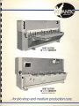
COST CUTTER
10' x Vi' CAPACITY
-J
COST CUTTER
10' x V2" CAPACITY
SHOWN WITH OPTIONAL TABLE
.. .for job shop and medium production runs