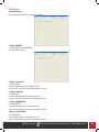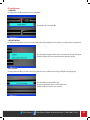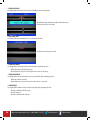
1
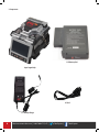
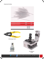
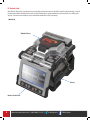
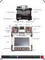
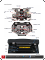
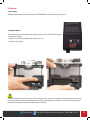
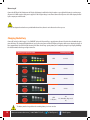
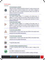
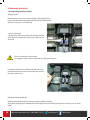
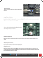
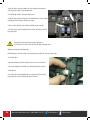
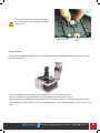
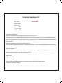
SUPER COUGAR CORE ALIGNMENT FUSION SPLICER
INSTRUCTION MANUAL
Please read through this manual completely before its first use.
1.800.5000.FIS(347) • fiberinstrumentsales.com
@FiberExperts |
/FiberExperts | fiberinstrumentsales.com | 1.800.5000.FIS (347)
1
TABLE OF CONTENTS
2
I . For Your Safety
3
II . Specifications and Components
1. Specifications
2. Components
3. Requirments for splicing
5
6
7
VIII. Data Sync
1. Running Data Sync
2. Setting - COM PORT
3. Setting – Splice Mode
4. Setting – HEAT Mode
5. Setting – MOTOR OFFSET
6. Memory – SPLICE RESULT
7. Memory – SPLICE IMAGE
8. Production - Serial Number
9. Production – Production Date
10. Production – A/S Date
11. Production – Total Electrode
12. Production – Electrode
13. Firmware Update
51
51
51
51
51
51
52
52
52
52
52
52
52
III. Product Description
1. External appearance of SUPER COUGAR
2. Arc fusion splicing assembly
8
10
IV . Operation
1. Supplying power
11
V . Menu Description
1. Function buttons
2. Turning on SUPER COUGAR
3. Installing the protective sleeve loader / cooling tray
4. Cleaning optic fibers
5. Inserting fiber into the protection sleeve
6. Cleaning and removing the skin of fiber
7. Cutting an optic fiber
8. Placing the fiber in the splicer
9. Splice procedure
10. Removing spliced fiber
11. Installing the sleeve on the sleeve heater
12. Heating the protection sleeve
13
15
15
15
16
16
16
17
17
20
21
22
IX. Error Messages
1. Fiber Dirty
2. Replace Position
3. Too Long Fiber
4. Fiber Over Angle
5. Loss Limit Over
6. Fiber Thin Error
7. Fiber Thick Error
8. Core Bubble
53
53
53
54
54
54
54
54
VI . Maintaining Splice Quality
1. Cleaning and examination prior to splicing
2. Regular maintenance and cleaning
X. How to deal with splicing problems
1. When the splice loss is too high
2. Abnormal operation of arc fusion splice
55
55
22
23
VII. Menu
1. Splice menu
2. Heater menu
3. Additional functions for splice
4. Checking splicing result
5. Calibration
6. Electrode
7. Locking menu
8. Settings
9. Information
26
33
35
37
39
43
45
45
49
XI. Q&A
1. Power
2. Splice operation
3. Operation of the tube heater
4. Maintenance
5. Other settings
56
56
57
57
58
XII. Warranty Period and Contact Information
1. Warranty period and services
2. Before sending the arc fusion splicer to us
3. Information required for repair
4. Transport
5. Repair
59
59
59
59
59
Product Warranty
60
fiberinstrumentsales.com | 1.800.5000.FIS (347) |
@FiberExperts |
/FiberExperts
I. Safety Guide
Super Cougar has been designed and produced to maximize the user’s convenience for both outdoor and indoor works, so its operation is easy and
simple. However, we strongly recommend our customers to read this service manual carefully prior to running the device in order to prevent any
accident and breakdown because improper handling of Super Cougar may cause serious danger. This service manual provides all the necessary
information to ensure splicing safely.
• Keep this service manual with the device at all times
Fiber Instrument Sales is not responsible for equipment damage and personal or physical damage caused by improper use or modification.
WARNING
Please, turn off the power of the device immediately and contact FIS co. ltd if any of below mentioned incidents occurs while operating the machine.
• Fumes, bad odor, noise or overheating
• Liquid or foreign substances falls into the device
• The arc fusion splicer is dropped or damaged
Use the power cord provided with the device. Using an inappropriate AC power cord may cause fire, electric shock or injury.
DO NOT touch the electrode when the power of SUPER COUGAR is ON. The high voltage and temperature may cause electric shock or burn.
Connect the AC power cord to the battery charger provided with the device and wall outlet. Check to ensure no dust or foreign substance on the AC
plug electrode before connecting it.
Unsafe connection may cause the occurrence of fumes, fire or damage to the device resulting in fire or serious injury or death.
Apply correct voltage.
The correct input AC power to the adapter is AC 100-240V and 50-60Hz.
Examine the input AC power before applying. Applying incorrect AC power could result in electric shock, equipment breakdown, serious injury or
even death. Abnormally high AC voltage or irregular frequencies are often generated by AC generator; hence it is necessary to check the AC output
power with a circuit tester. Since abnormal high voltage and frequencies may result in serious electric shock, injury, death or damage to the equipment, it is important to regularly check the operation status of the generator before use.
DO NOT excessively pull, amend, misuse or apply heat to the AC power cable provided by the company. Using a damaged power cable may result in
fire or injury.
Connect 3-core Ac power cord. DO NOT use 2-core, cable and plug.
@FiberExperts |
/FiberExperts | fiberinstrumentsales.com | 1.800.5000.FIS (347)
3
DO NOT touch the AC plug, AC power cable or the arc fusion splicer with wet hands. It may cause an electric shock.
DO NOT disassemble the AC adapter, battery or the arc fusion splicer. Any amendment or changes of SUPER COUGAR may cause fire, electric shock or
injury.
When using an external battery pack, follow instructions below.
• Using improper external battery may cause fumes, damage to the device, burn, serious injury or even death.
• DO NOT throw the battery into fire or a trash incinerator.
• DO NOT charge the battery near flame or fire.
• DO NOT excessively or apply physical shock to the battery.
• If the batter is not fully charged or green LED is not turned on in about six hours, stop charging immediately and contact FIS co. ltd. DO NOT put any
object on the AC adapter while it is being charged.
Use the adapter (S311) and battery pack (S313) that are provided by the company at all times. Using a different type of battery pack may cause
fumes, fire, damage to the device, injury and death.
Use the battery adapter provided by the company at all times.
DO NOT use other type of AC power cord.
Make sure that no short circuit is made in the terminal of the AC adapter (S313) and the battery. Excessive electric current may cause damage to the
machine and injury.
DO NOT run SUPER COUGAR in an environment there is flammable liquid or toxic gas. The electric arc of the arc fusion splicer may cause fire or explosion.
DO NOT clean SUPER COUGAR using compressed air or gas.
Check the condition of belt to ensure that it has no damaged or worn out parts before transporting the carrier case using the belt. If the carrier case
is dropped due to worn out belt, it could damage the machine or people could get hurt.
Make sure to wear protective glasses while performing splicing works. If fiber fragments come into contact with the eye or skin, it can be extremely
dangerous.
DO NOT operate the arc fusion splicer at a high temperature or near heat, otherwise injury or damage to the device may occur.
Take extra caution when handling the heater part whose surface is extremely hot.
DO NOT touch it by hand and make sure nothing contact it.
4
DO NOT TOUCH
EXTREMELY HOT
fiberinstrumentsales.com | 1.800.5000.FIS (347) |
@FiberExperts |
DO NOT SPARY FREON GAS
/FiberExperts
WARNING
DO NOT touch the tube heater or the protection sleeve during or immediately after heating them. The hot surface may cause injury.
DO NOT place SUPER COUGAR in an unstable or unbalanced place. The machine may fall, causing injury or damage to the machine.
SUPER COUGAR has to be precisely adjusted and aligned. DO NOT allow the unit to receive a strong impact. Use the supplied carrying case for its transportation
and storage. The carrying case protects SUPER COUGAR from breakage, moisture, shake and shock during storage and transportation.
Replace the electrode in a timely manner and maintain it as instructed below;
• Use only a specified electrode.
• Place a new electrode in the correct position.
• Replace the electrodes as a pair.
If the user fails to follow the above instructions, it may cause abnormal arc-discharge, resulting in damage to the machine or degradation in splicing performance.
Use no chemicals other than ethyl alcohol (96% or greater) to clean the objective lens, V-groove, windshield mirror, LCD monitor and body of the machine.
Otherwise, blurring, discoloration, damage or performance deterioration may occur. SUPER COUGAR requires no lubrication. The use of oil or grease may degrade
its performance and damage to the equipment
DO NOT store the device in a place where temperature or humidity is high. Damage to the machine may occur.
The technical examination of SUPER COUGAR must be carried out by a qualified engineer; otherwise, fire or electric shock may occur. If any problems occur,
contact FIS co. ltd for repair and maintenance.
II. Specifications
1. Specifications
Subject
Description
Arrangement
Applicable fiber types
Applicable diameters of fiber
Cut length
Splice loss (Typical)
Splice reflection loss
Operation time
Operation programs
Splice result count
Recommend temperature and humidity range for
operation
Recommended temperature range for storage
Wind protection
Specification
Connection terminals for external device
Power
External power
Running times when using the battery pack
Replacement cycle of electrodes
Tension stress test
Display
Fiber view and magnification
@FiberExperts |
Core to core type
SMF(ITU-T G.652), MMF(ITU-T G.651), DSF(ITU-T G.653), NZDSF(ITU-T G.655), EDFA, EI980, possible to
splice different kinds of fibers (SM/MM), ITU-T G.657
Clad : 80µm ~ 150µm, Coating : 100µm ~ 1000µm (Single)
250µm (Coat) : 8 ~ 16mm, 900µm : 16mm
SMF : 0.02dB, MMF : 0.01dB, DSF : 0.04dB, NZDSF : 0.04dB
>-60dB
Splice time: about 9 seconds, heating time: about 26 seconds (when using a S-160 (60mm) tube)
Splice mode: 100, Heater mode: 50
Up to 2,000 times
-10°C to 50°C, humidity : 95%, non-condensing
-40°C to 80°C, 0 to 95% RH
15m/s
138W×160L (including the monitor), 2.3Kg (including the battery pack)
USB, RCA, external power
DC 14.8V battery (5600mAh) pack, 100 ~ 240V AC adapter
Vehicle cigar jack (DC 12V)
About 200 times (S313)
After 2,000 times of splicing
2N/4.4N (OPTION)
Two CMOS cameras and 4.3” color LCD monitor with touch panel
X/Y 300X, 170X
/FiberExperts | fiberinstrumentsales.com | 1.800.5000.FIS (347)
5
2. Components
S313 Battery Pack
Super Cougar Body
AC Cord
S-11 Battery Charger
6
fiberinstrumentsales.com | 1.800.5000.FIS (347) |
@FiberExperts |
/FiberExperts
3. Requirements for Splicing
Fiber Optic Basic Protection Sleeves
Fiber Optic Micro Protection Sleeves
0.25mm
0.9mm
40mm length
60mm length
0.25mm
0.9mm
20mm length
25mm length
34mm length
45mm length
FIS Fiber Stripper F1-1301T
Alcohol Dispenser
@FiberExperts |
Fiber Optic Cleaver
F1-LYNX
/FiberExperts | fiberinstrumentsales.com | 1.800.5000.FIS (347)
7
III. Product Guide
Optical fiber arc fusion splicer Super Cougar has been designed for splicing various types of optical fiber using IPS system technology. In order to
meet the work condition of both inside and outside, it is small light and easy to operate maintaining very low rate in splice loss and fast splice
capacity. Users have to read carefully the service manual for the maximum use of the Super Cougar.
1. Main Body
Windshield Cover
Battery
Monitor (Touch Panel)
8
fiberinstrumentsales.com | 1.800.5000.FIS (347) |
@FiberExperts |
/FiberExperts
@FiberExperts |
/FiberExperts | fiberinstrumentsales.com | 1.800.5000.FIS (347)
9
2. Parts for Fusion Splicing
Heater Cover
Heater 1
Center
Heater
Heater 2
Cover close level
10
fiberinstrumentsales.com | 1.800.5000.FIS (347) |
@FiberExperts |
/FiberExperts
IV. Operation
1. Power Supply
The high performance battery and its power adapter allow SUPER COUGAR to be operated while it is being charged.
Charging the Battery
Connect the adapter to the DC jack of the battery and the AC cord to a wall AC outlet. The LED is changed to
green when the charging is
completed. Since the floating charging method is applied to S3, it can
run while it is being charged.
The battery pack includes the protection circuit so that over discharge and over charge can be prevented. The supply of power stops once the protection circuit is activated. In order to deactivate the protection circuit and resume feeding power, wait about 10 seconds and connect the DC plug to
the DC jack of the battery pack and the AC cord of the charger to a wall outlet.
@FiberExperts |
/FiberExperts | fiberinstrumentsales.com | 1.800.5000.FIS (347)
11
When using AC
Connect the DC Plug of the AC adapter to the DC jack of the battery installed in the body. An amber or green light of the battery is on when proper
AC power is fed. Make sure the rated power is supplied. 250V or higher voltage is not allowed. Connect the AC power cable of the adaptor provided
by the company to a wall AC outlet.
Never use an adapter other than the one provided with the machine; otherwise an incident such as fire may occur.
Charging the battery
Connect DC cord of specified charger S-11 to “CHARGER” jack on the left part of large-capacity battery. Connect AC cord to the outlet with the appropriate AC voltage. The charging LED light blinks red, green, yellow in sequence and the LED lights up red again, which means charging has begun. It
takes approximately 3 hours for the built-in battery and 6 hours for the large-capacity battery to be completely charged. Keep charging for buffing
for about 30 minutes after the green light is turned on.
Remaining capacity indicator (LED)
Remaining Capacity
5 LED
80-100%
4 LED
60-80%
3 LED
40-60%
2 LED
20-40%
1 LED
1 LED (blinks)
10%
5% (Immediate charge needed)
The battery must be charged when the remaining battery is as low as one bar.
12
fiberinstrumentsales.com | 1.800.5000.FIS (347) |
@FiberExperts |
/FiberExperts
V. Menu Description
1. Function Keys
@FiberExperts |
/FiberExperts | fiberinstrumentsales.com | 1.800.5000.FIS (347)
13
14
fiberinstrumentsales.com | 1.800.5000.FIS (347) |
@FiberExperts |
/FiberExperts
2. Turning on the Super Cougar
Monitor angle
The angle of the monitor can be adjusted to provide a better view
Monitor ON
Press the power key for about 0.5 second without opening the windshield cover. The initial screeen is displayed after resetting all the motor to their
respective initial position.
Initial Screen
It is important to choose a right splice mode to ensure an accurate splicing result. The current splice mode is displayed on the initial page. A right
heater mode must be selected to heat the protection sleeve. The current heater mode is displayed on the initial page.
• Press MENU key to change splice mode on the initial
page.
• The splice mode and heater mode are displayed on the
screen.
3. Installing the protection sleeve loader / cooling tray
Pull out the protection sleeve loader and inset it into the right or left groove. Insert the cooling tray into the groove at the rear side of the heater.
4. Cleaning Optical Fibers
Cleaning carefully the optic fiber with with a piece of soft cloth or cotton swab soaked in alcohol. Fine dust on the coated surface of the fiber can
cause the break off or decrease once the fiber is set inside the protection sleeve.
@FiberExperts |
/FiberExperts | fiberinstrumentsales.com | 1.800.5000.FIS (347)
15
5. Inserting optical fibers into protective sleeves
Insert the fiber into the protection sleeve.
Sleeve
Fiber
vV
vV
6. Cleaning and stripping optical fibers
Strip about 4 cm of coating from the fiber end with a coating stripper. Clean the bare fiber
7. Cleaving bare optical fibers
1. Place the bare fiber in the cleaver to give the desired cleave
length.
2. Gently lower the cleaving lever. Now the fiber is cleaved.
3. Raise the cleaving lever and take out the fiber.
4. Remove the cut end of the fiber and throw away in a proper
container.
For more details concerning the use of cleaver, refer to the cleaver instruction guide.
16
fiberinstrumentsales.com | 1.800.5000.FIS (347) |
@FiberExperts |
/FiberExperts
8. Placing the fiber in the splicer
Open the windshield and holder of the fixer.
Place the fiber between the V-groove and the electrode.
V-Groove
Electrode
If the coating part of the fiber is bent, please have the bending part face the floor.
9. Splicing Procedures
The condition of the fiber can be observed via the image processing system installed in Super
Cougar. However, an examination with operator’s naked eyes is necessary to ensure better splice result.
The fibers installed in the splicer move toward each other. The moving fibers can
stop at precise positions at which point splicing can be carried out after completing a discharge for cleaning. Then, the cut angle, physical condition of the tip area
and dust existence need to be checked. If the measured cut angle is bigger than
the preset limit value or any damage to the fiber is discovered, an error message appears on the screen and the splice process stops. If no error message appears on the screen, examine the condition of the cross sections with your eyes
based on following figures. Any fiber that has similar condition to any of below
figures has to be removed and a new fiber must be placed. These general defects
can cause a wrong splice.
@FiberExperts |
/FiberExperts | fiberinstrumentsales.com | 1.800.5000.FIS (347)
17
Cracked Broken Tilted The fibers whose examination has completed are arranged core to core or clad to clad. The measured values of clad axis deviation and core axis
deviation can be displayed on the screen.
• It is possible to set the fibers not to be arranged after checking the cut angles.
• The maximum limit of cut angle can be changed.
• Press SET key to proceed to the next step ignoring the error message about the cut angle.
• It is possible not to display the cut angle and the deviations of clad axis and core axis during
arc fusion.
Discharge is carried out to perform splicing the fiber after completing the arrangement of the fibers.
The discharge is initiated when the ARC key is pressed after completing the arrangement in non-continuous operation mode.
The splice loss value is measured after completing arc fusion and display on the screen. The loss value is affected by error elements. And, these
elements also influence the estimation and computation of the value.
The computation of the loss value is based on such clear measurement factors as MFD. If the measured cut angle or computed loss value is greater
than the preset limit, an error message appears on the screen. Also, an alarm can be triggered by the discovery of an abnormal condition of the
spliced part including too thick or thin area or bubbles. Even if an error message does not occur, it is recommended to perform the arc fusion process
again if the result on the screen does not look good enough when examining it with naked eyes.
Sometimes, the spliced area can seem fatter or larger than other part. This is normal situation and does not affect the splice loss.
Please refer to relevant parts for more information about changing the limit values of computed splice loss or cut angle.
18
fiberinstrumentsales.com | 1.800.5000.FIS (347) |
@FiberExperts |
/FiberExperts
The splice loss can be corrected and improved in some cases via conducting additional arc fusion. Press ARC key to conduct additional arc fusion,
which will perform the computation of splice loss value and check the condition of the spliced area.
However, in some cases, the splice loss can be aggravated by performing additional arc fusion splicing; hence the operator can set the
additional discharge off or limit the number of discharge.
Growth of splice loss: Causes and Corrective Measures
@FiberExperts |
/FiberExperts | fiberinstrumentsales.com | 1.800.5000.FIS (347)
19
A vertical line appears on the spliced area sometimes when splicing multimode fibers or not similar fibers (i.e. whose diameters are different). However, it does not affect the splice loss or the splice quality including tensile strength.
Saving splice results
The splice result can be saved and the procedure is as follows Total 2,000 results can be recorded and the 2001th result will be warren on the line of
the 1st result.
How to automatically save splice results (a note cannot be entered)?
When SET or RESET is pressed after completing splicing, the result is saved automatically. Or, it can be recorded when the windshield is opened after
completing a splice process on the last screen.
10. Removing the spliced fiber
1) Open the sleeve heater cover
2) Open the windshield cover
3) Hold the left fiber with your left hand from the edge of the windshield and open the left fixer cover.
4) Open the right fixer cover
5) Hold the right fiber and remove the spliced fiber from the splicer
Keep holding the fiber until transporting it to the tube heater.
20
fiberinstrumentsales.com | 1.800.5000.FIS (347) |
@FiberExperts |
/FiberExperts
11. Installing the Protection Sleeve in the Sleeve Heater
Transfer fiber with protection sleeve to tube heater. Slowly move the spliced
fiber from the right until it reaches to the left hand at the edge of the tube
heater. Place the protection sleeve in the middle of the tube heater.
Make sure that the splice point is placed in the middle of the protection sleeve.
12. Heating the protection sleeve
• Transfer the fiber with protection sleeve to the center of the tube heater.
• Place the fiber with protection sleeve in the tube heater. Be sure to keep tension downwards on the fiber as it is placed, so that the tube heater lid
can automatically close. (The upper heater is only applied.)
• Press the HEAT key to start the heating cycle. When the heating process is completed, the HEAT LED(red) turns off.
• Open the tube heater lids and remove the protected fiber from the tube heater. Apply only a small amount of tension to the fiber while removing
it from the tube heater.
• Visually inspect the finalized sleeve to verify no bubble or debris/dust is present in the sleeve.
• Ensure that the protection sleeve is centered over the splice point.
• Ensure that the supporting bar in the sleeve is located
If the HEAT key is pressed during sleeve heating, the sleeve heating process is aborted.
In isolated cases, the sleeve may stick to the bottom plate of the heater. If this happens, use a cotton swab to help remove the sleeve
from the heater.
@FiberExperts |
/FiberExperts | fiberinstrumentsales.com | 1.800.5000.FIS (347)
21
VI. Maintaining Splice Quailty
1. Cleaning and inspection before splicing
Cleaning of V-grooves
Contaminants in V-grooves do not assure proper holding, resulting in high splice loss.
V-grooves must be frequently inspected and regularly cleaned up even during its daily
operation. To clean V-grooves, see the following.
• Open the wind protector.
• Brush the surface of the V-grooves with a cotton swab moistened with
alcohol. Remove the remaining alcohol in the V-grooves with a dry clean
cotton swab.
V-Groove
• Please be careful not to touch the electrodes.
• Do not apply too much force when cleaning. It may cause damage to the V-grooves.
If contaminants in V-grooves are not fully removed with a cotton swab
moistened with alcohol, use the ends of cleaved optical fibers to remove
them. Then, repeat the step 2.
Cleaning of the fiber clamp holder chip
Contaminants in holder clamp chip do not assure proper holding, resulting in lowquality
splicing. Holder clamp chip must be frequently inspected and regularly cleaned up even during its daily operation. To clean V-grooves, see the following.
22
fiberinstrumentsales.com | 1.800.5000.FIS (347) |
@FiberExperts |
/FiberExperts
• Open the wind protector.
• Clean the surface of holder clamp chip with a thin cotton swab moistened
with alcohol.
Cleaning of the glass of wind protector
Contamination on the glass of wind protector reduces the transparency of light guide. If so, optical fiber core position becomes unclear, resulting in
high splice loss. To clean the glass, take the following steps.
• Clean the surface of the mirror with a lens cleaner. Remove the remaining
alcohol on the glass with a dry clean cotton swab.
Cleaning of the optical fiber cleaver
Contamination of a blade or a clamping pad of the fiber cleaver lowers the performance of the cleaver and contamination of the fiber surface or
ends may.
2. Regular inspection and cleaning
Regular inspection and cleaning are required to maintain high-quality splice.
Cleaning of the object lenses
Contamination on the surface of the lens makes it difficult to recognize the fiber core position, resulting in high splice loss. If this happens, the
splicer fails to work properly. To prevent this, clean two object lenses at regular intervals. If you don’t, dust will accumulate and it will be impossible
to remove it. Cleaning process of the lenses is as follows.
@FiberExperts |
/FiberExperts | fiberinstrumentsales.com | 1.800.5000.FIS (347)
23
• Clean the surface of the mirror with a lens cleaner. Remove the remaining
alcohol on the glass with a dry clean cotton swab.
• Turn off the splicer before cleaning the object lenses.
• Clean the surface of the lens(X axis & Y axis) softly with a lens cleaner. Remove
remaining alcohol on the glass with dry clean cotton.
• The lens surface should be clean and there should be no line and stain.
• Turn on the power and check whether there is no line and stain. Press the X/Y
key to change the
• Remove the electrodes before cleaning the object lenses.
• Be careful not to reach the end of the electrode while cleaning the lenses.
Replacement of the glass of wind protector
If the fiber image is not clear enough, or the stain remains even after the clean-up, do these steps.
• Turn off the splicer.
• Open the wind protector. Remove the glass with a cross-head screwdriver.
• Take out the shaft pin inserted in the glass and reinsert it in the new glass.
• Clean the glass
• Turn on the power and confirm that there is no line and stain. Press the X/Y
key to change the screen and inspect the surface of the lens.
24
fiberinstrumentsales.com | 1.800.5000.FIS (347) |
@FiberExperts |
/FiberExperts
Please be cautious not to lose the spring. Confirm that the
glass is properly replaced. If not so, optical fiber can not be
exactly observed.
Spring insertion part
Shaft pin
Blade position adjustment
If the cleaver fails to work properly, rotate the blade 1/16th of a turn to replace the worn out blade position with a sharp blade position. To rotate
the blade, see the following.
• Loosen the wrench bolt a little on the right of the cleaver with the hex wrench on the lower part of the cleaver.
• Rotate the circular blade to change the position with a cotton swab. (Adjust it to have the blade number face up.)
• Tighten the wench bolt on the right of the cleaver. Be careful not to touch the blade when rotating it. Use a thin cotton replace the hex wrench
in its original position. To replace the blade, see the operation manual of the cleaver. If the 16 positions of the blade are all worn out, replace the
blade.
@FiberExperts |
/FiberExperts | fiberinstrumentsales.com | 1.800.5000.FIS (347)
25
VII. Main Menu
1. Select Splice mode
The optical splice setting for the exact optical fiber assembly comprises the splicing factors described below. These factors are dependent on optical
fiber assembly and the difference in optical fibers.
• A factor to adjust arc/heating
• A factor to calculate estimated loss
• A factor to adjust fiber alignment and splicing process
• The limit value for an error message
These splicing factors are already stored in the fusion splicer. They are stored in the database and can be used by coping in the user program. They
can also be edited for exact fiber assembly.
Splice Mode
Details
In this mode, the core profile of the fiber is observed and optical fibers are automatically spliced.
The key point of AUTO mode
NZDS optical fiber is spliced through the basic NZDS splice mode. But for the best results, the optimal
splice mode suitable for NZDS fiber is recommended. It is because of the nature of the fiber.
Mode for splicing the basic single mode fiber. MFD is 9~10um at 1310nm
wavelength.
Mode for splicing NZDS fiber. MFD is 9~10um at 1550nm wavelength. It can also splice WDM fiber.
Mode for splicing DS fiber. MFD is 7~9um near 1550nm wavelength.
Mode for splicing the multimode fiber.
Core diameter: 50.0 ~ 62.5um
Attenuation splice
Others are not mentioned above and stored in the database of the splicer. New splice modes will be
added continuously. For more information concerning recent new modes, contact Fiber Instrument
Sales.
AUTO
SM
NZ
DS
MM
AT1/AT2
OTHERS
Selecting a splice mode
Select a splice mode suitable for the prepared optical fiber.
In ready status, press “MENU” key or touch “MENU” icon on the screen to open menu. The splice mode is displayed when the splice menu is touched
or selected using the “Enter” key.
Ready Screen
26
fiberinstrumentsales.com | 1.800.5000.FIS (347) |
Menu Screen
@FiberExperts |
/FiberExperts
• Move the selection bar up and down using arrows and enter to select, or, simply tap the desired mode on the screen and touch “Select” again.
Press ESC key or touch Close on the screen to end the splice mode selection menu.
Creating or erasing a splice mode
Splice mode setting
Selection menu for fiber type
The created splice mode
@FiberExperts |
/FiberExperts | fiberinstrumentsales.com | 1.800.5000.FIS (347)
27
How to change the splice mode
Next, touch “Replace” on the screen. Move to the new splice mode just created and press “ENTER”. Or, touch the mode and “OK” on the LCD.
Splice mode
Selection of the mode to be changed
The modes that are created and listed after number 20 on the list can be changed.
How to change the splice mode
A splice mode can be deleted. Follow the instructions below.
Select the desired splice mode and press the right arrow key to open the splice mode edit menu. Press “ENTER” key to select the fiber type.
Select “0:BLANK” and press “ENTER” to activate it.
• Splice modes from 1 to 20 on the list cannot be deleted.
• Mode number 1 is automatically selected when a splice mode is deleted
Editing reference or splice modes
The splice parameters belonging to each splice mode can be modified. The two most important factors
– discharge(arc power) and time – can be amended as:
Splice mode setting
• Press the right direction arrow to display the splice mode edit on the splice mode setting. Or touch “Edit”.
• Move the cursor to the element that needs to be changed by pressing the up and down keys or touching the screen.
• Press right arrow or touch “Edit” to select a parameter. The values can be adjusted using right or left direction key or touching the screen in each
parameter edit screen.
• Press “ENTER” to save the changed value..
28
fiberinstrumentsales.com | 1.800.5000.FIS (347) |
@FiberExperts |
/FiberExperts
Splice mode setting
Changing the value
The list of the splice factors for splice modes including AUTO, SM, DS, MM and NZ is presented below.
Only some parameters shown below are displayed on the screen in the Auto, SM, DS, MM and NZ modes for the sake of easy operation. Other
parameters that are not shown on the screen have been set to the most appropriate values in the factory.
Parameter
Fiber type
Mode Title 1
Mode Title 2
Cleave Limit
Loss Limit
Arc Power
Arc time
Clean time
Re-arc time
Description
The splice modes saved in the database are displayed. The mode selected by the user is copied to the splice mode in the user side program.
The titles of splice modes are displayed in 11 characters.
Detailed description of the splice modes are described as 11 characters. The titles are presented in the splice edit mode.
An error message appears if the cleave angle of either left or right end of fiber exceeds the limit.
An error message appears if the estimated splice loss value exceeds the limit.
The discharge amount is set differently for each mode
The discharge time is set differently for each mode and automatically decided in accordance with fiber type when the auto mode is
selected.
The discharge for cleaning occurs for a short time for burning the fine dust on the fiber surface. It can be modified in this parameter.
In some cases, the splice loss can be improved by applying additional discharge. The duration of the re-discharge can be modified here.
Selecting Splice Modes for the Best Results
Testing by FIS Technicians indicates that for the best results with the Super Cougar splicer:
When setting up the splicer, select your specific fiber type (ie: SM; MM1; MM2; etc.) in the “Splicer Mode Menu”.
Results will be more consistent and accurate by selecting the fiber type rather than using the “Mode 1 Auto” setting.
@FiberExperts |
/FiberExperts | fiberinstrumentsales.com | 1.800.5000.FIS (347)
29
Splice edit mode
The splice mode edit enables users to set various splice modes and use them in a proper way in their working conditions. Instructions for using various parameters and their functions are described below.
Parameters
Fiber type
Mode Title 1
Mode Title 2
Alignment
Focus-L
Focus-R
Arc Power
ECF
Auto power
Proof test
Cleave Limit
Loss Limit
Fiber Angle Limit
Cleaning arc time
Gap
Gap set Position
Prefuse POWER
Prefuse time
Overlap
ARC1 POWER
Arc1 time
ARC2 POWER
Arc 2 time
Arc ON - Time
Arc OFF - Time
Re-arc time
30
Description
The list of splice modes stored in the splicer database appears on the screen. The user selects a proper mode to use. It is utilized in
using the edit function by copying a similar mode from the splice modes stored in the database.
Mode title 1 expresses the splice mode in maximum 11characters.
Mode title 2 expresses the splice mode in details in maximum 11 characters. Mode title 2 can be found in the [Splice mode] menu.
It sets the method of fiber alignment.
“Core”: optical fibers are aligned to core position on both sides.
“Clad”: fibers are aligned to the Gap set Position of clad.
It sets the focus during the fiber observation. A focal plane moves towards the core due to numerical value increase and the focal
plane moves against the core due to numerical value decrease. “AUTO” focus setting is recommended. The left fiber and the right
fiber are focused respectively and it is possible even when different fibers are spliced.
Attenuation splice
When aligning optical fibers by using the ECF function, it sets the axial offset.
Cleaning arc burns dust on the fiber surface even in a short time of arc. The duration of cleaning arc can be affected by this factor.
If [Proof test] is set to “ON”, the test is conducted by opening the wind protector after splicing or pressing the SET key.
It sets the error range of cleave angle. If at least one out of the measured left and right cleave angles exceeds the error range, an
error message appears.
It sets the error range of estimated loss. If the estimated loss exceeds the error range, an error message appears.
If the bending of the two spliced fibers exceeds the preset limit, an error message appears.
When the section gap between fibers is set, a short arc is conducted to remove fine dust on the fiber surface. The execution time of
cleaning arc is set in this domain.
It sets the section gap between left and right during alignment and initial arc.
It sets the position of the fiber to splice at the center of arc. If the MFD values of left and right fibers are different, splice the fiber
with the smaller value. Splice loss can be improved by transferring the gap setting position from the arc center to the bigger MFD
fiber.
It sets a span of time from the start of arc to fiber proceeding as the initial ARC POWER. In this point, if initial ARC POWER value
is low, the section angle of the fiber can be bad, resulting in an axial offset. If the value is too high, the fiber can be burning or
become round, causing the deterioration of splice loss.
It sets a span of time from the start of arc to fiber proceeding as the initial arc time. Long [initial arc time] means high [initial ARC
POWER].
It sets the overlapping of fiber in the amount fiber advancing. If [initial ARC POWER] is weak or [initial arc time] is short, make the
[overlap] setting somewhat small. In opposite cases, make the setting somewhat big.
A major arc can be adjusted in two steps. The first step of arc is ARC POWER 1 and the second step is ARC POWER 2. ARC POWER 1 is
set in this domain.
It sets the time of ARC POWER 1.
ARC POWER 2 is the second step. ARC POWER 2 is set in this domain.
It sets the time of ARC POWER 2.
In general, [ARC2 Time] is set to “OFF.” It is possible to set a very long arc time, but if the arc time 1 or 2 is more than 30 seconds, the
arc unit can be damaged.
It sets the ARC POWER to ON and OFF one after the other as ARC POWER 2 is being arced. “ON” time of ARC POWER 2 is set in this
domain. Have arc time set to ON always for a re-arc.
It sets the arc time OFF of ARC POWER 2.
When the arc of ARC POWER 2 is stopped in isolated cases, re-arc may also be stopped. If continuous re-arc is needed, set this
parameter to “OFF.”
It sets re-arc time.
It automatically sets re-ARC POWER in the [splice mode edit] menu to arc the same amount as [ARC POWER 2]. If ARC POWER 2 is
set to ON and OFF, re- arc is automatically set to ON and OFF.
fiberinstrumentsales.com | 1.800.5000.FIS (347) |
@FiberExperts |
/FiberExperts
Parameters
Taper splice
Taper Wait
Taper Speed
Taper time
Estimation mode
MFD - Left
MFD - Right
Deviation
Core arrangement
proceed
Core irregularity
Inconsistent MFD
Description
Thin fibers increase splice loss in isolated cases. This taper unction is set to “ON.” Taper shape is determined by these three parameters.
It designates a span of time from the end of the fiber advancingamount to the start of taper.
It designates the taper speed of the fiber.
It designates the taper time of the fiber.
“OFF”, “”Core” or “Clad”
Selects “Clad” when splicing MMF.
Selects one of these splice loss estimation modes.
It sets the MFD value of the left or right. Estimated splice loss values for both the left MFD and the right MFD have to be calculated.
It refers to the sum of the initially measured splice loss value and increased loss value. When splicing specialty fiber or different
kinds of fiber, a high splice loss may occur even under an optimized arc condition. The minimum value of the actual splice loss has to
be set in order to accord the actual splice loss value with estimated splice loss value.
Core arrangement proceed, Core irregularity and Inconsistent MFD affect the measurement of splice loss. If the estimated mode is
set to “OFF” or “Clad”, the core step, core irregularity and MFD defect are automatically set to “OFF”. If the splice estimation needs to
be adjusted, it is done using Core arrangement proceed, Core irregularity and Inconsistent MFD.
@FiberExperts |
/FiberExperts | fiberinstrumentsales.com | 1.800.5000.FIS (347)
31
How to insert mode Title / Note / Password
The list of characters is displayed below when choosing the mode title, note or password.
Select desired characters using up, down, left and right keys or touching each
character on the screen. Then, press “ENTER” to confirm the selections.
Confirm the selection of characters by pressing “ENTER” or touching “Done”
on the screen.
Attenuation splice mode
The attenuation mode is designed to attenuate the focal point of splice by intentionally generating the deviation of axes; it consists of two types.
At least one of “AT1(SM)”,
“AT1(DS)”, “AT2(SM)”, “AT2(DS)”
and “AT2(MM)” is selected.
[AT1] mode
[AT1] performs fiber splice intentionally using the core axis deviation. [AT1] displays the estimated splice loss value. This data is not an accurate loss
value but just a reference. It is recommended to use a power meter to measure the accurate splice loss value.
32
fiberinstrumentsales.com | 1.800.5000.FIS (347) |
@FiberExperts |
/FiberExperts
2. Select Heater Mode
The heater mode consists of 12 different modes. The operator needs to choose the most appropriate heater mode prior to using the protection
sleeve. The protection sleeve type determines the tube heat functions. The reference of this mode can be found in the database. Any contents
required can be copied to and amended in the user’s program.
Parameters
Description
S-160
A mode to heat standard 60mm sleeves.
S-140
A mode to heat standard 40mm sleeves.
34mmA
A mode to heat standard 34mm macro sleeves
25mmA
A mode to heat standard 25mm macro sleeves
20mmA
A mode to heat standard 20mm macro sleeves
40mmB
A mode to heat standard 40mm macro sleeves
34mmB
A mode to heat standard 34mm macro sleeves
25mmB
A mode to heat standard 25mm macro sleeves
20mmB
A mode to heat standard 20mm macro sleeves
45mmC
A mode to heat standard 45mm macro sleeves
34mmC
A mode to heat standard 34mm macro sleeves
25mmC
A mode to heat standard 25mm macro sleeves
Selecting heater mode
Select a heater mode most suitable for the optical fiber protection sleeve to use.
The menu appears when “MENU” is pressed or touch “MENU” icon on the screen in ready mode. The heater mode is displayed when selecting the
heater menu with the cursor or touching it.
@FiberExperts |
/FiberExperts | fiberinstrumentsales.com | 1.800.5000.FIS (347)
33
Use up and down keys to select a heater mode and press “ENTER” to confirm the
selection. Or, select a heater mode by touching it and touch “Select” to confirm it.
Setting a heater mode
Edit heater mode
It is possible to edit or amend the modes of the tube heater, which are saved in the database.
Select the edit mode in the [Heater mode selection] menu using the cursor. Click it to display [Heater mode edit].
Select Heater Mode
Editing each element
Move the cursor to a desired location by using up and down keys or touching the screen.
Press right arrow key or touch “Edit” to select an item. The value of each item can be adjusted by using left and right keys or touching the screen.
Press “ENTER” to save.
34
fiberinstrumentsales.com | 1.800.5000.FIS (347) |
@FiberExperts |
/FiberExperts
Parameters
Sleeve type
Mode title 1
Mode title 2
Heater Control
LONG
Heat time
Heat temperature
Finish temperature
Description
Sets the proper sleeve type. Entire heater mode list is displayed.
The selected mode will be copied to a user-programmable mode.
A heater mode title is displayed at the right bottom on the screen while splice and heating are
in operation. May use up to 5 characters.
• describe the heater mode on [sleeve type] screen.
• the maximum number of letters: 13
• set the order of heater Control LONG
• LONG 1: use 60mm protection sleeves
• LONG 2: use 60mm protection sleeves even for 8mmcleaved
and Ny-coated optical fibers
• MIDDLE: use 40mm protection sleeves
• MICRO 1: use micro sleeves for the fiber which has a outer
diameter of 900µm.
• MICRO 2: 34mm micro sleeves or a little long sleeves
• MICRO 3: 34mm micro sleeves or a little short sleeves
• Set heating time.
• Heating time is automatically controlled according to the air and
ambient temperature. Heating time may be longer or shorter than th
set value as [heat time].
• Set heater temperature.
• Nylon-coated optical fibers are used with cleaved 8mm and Ny
coating fibers are used as [heater temperature] is raised over 190.
• Set finish temperature.
• The sleeve may be removed after the heating is finished.
• [Caution] In the case of higher finish temperature, a buzzer sounds
before the sleeve is not cooled. When the sleeve is removed from the
tube heater at over 100, the remaining optical fiber at the splice point
may be pressured and modified.
• Set the temperature below 200°C when heating standard sleeves.
• At high temperature(over 150°C), do not set heating time to more than 120 seconds.
3. Additional functions for splice
There are 6 sub menus within the additional functions for splice menu under “OPTION”.
@FiberExperts |
/FiberExperts | fiberinstrumentsales.com | 1.800.5000.FIS (347)
35
General settings for the entire modes of splice and tube heater operation can be done.
Menu setting
Parameters
Auto start
Pause 1
Pause 2
Cleave angle
Axle Offset
Description
Set “Auto start” to “ON,” and auto splice operation is performed. Place optical fiber in the splicer and close the wind protector,
and the splice procedure is automatically started.
If “Pause 1” is set to “ON,” splicing is halted after the fiber gap adjustment is completed. Press the SET button, and splice
operation is conducted. The cleave angle is displayed during the pause.
If “Pause 2” is set to “ON,” splicing is halted after optical fibers are aligned. Arc splicing begins when the Arc button is pressed.
Data display
If it is set to “ON,” the cleave angle of the left and right fiber is measured and displayed on the screen.
If it is set to “ON,” the results on alignment Offset of the core andclad are displayed on the screen.
Displaying data
The user can choose whether to display the cut angle and axis offset on the screen during splicing.
Ignoring a splicing error
The user is allowed to choose whether an error is detected or not while the splice is in progress or when it is completed.
36
fiberinstrumentsales.com | 1.800.5000.FIS (347) |
@FiberExperts |
/FiberExperts
Parameters
Cleave
Loss
Dirty Fiber
Thickness
Bubble
Fiber too long
Description
If it is set to ON, an error message appears when the cleave angle set for each mode is exceeded.
If it is set to ON, an error message appears when the loss limit for each mode is exceeded.
If it is set to ON, an error message appears if the surface of the fibers placed in the splicer is not clean.
If it is set to ON, an error message appears when the spliced area of the fiber whose splice is done is too thick or thin.
If it is set to ON, an error message appears when bubbles are generated in the core of the spliced area.
If it is set to ON, an error message appears when too long fibers are placed in the V-groove.
Compensating discharge
Air pressure and temperature are crucial factors in arc discharge when performing a splice. Therefore, the user is allowed to choose whether to
compensate depending on air pressure and temperature.
TV Output
The contents of the splicer can be printed via external visual equipment and applicable output methods can be determined.
4. Checking arc fusion splice result
The splice result saved in the memory can be displayed and the saved result can be added or modified under “HISTORY”.
@FiberExperts |
/FiberExperts | fiberinstrumentsales.com | 1.800.5000.FIS (347)
37
Displaying splice result
The splice mode type, fiber condition, climate conditions and splice result can be verified. Select a desired item among the displayed splice items
and press “ENTER” key.
Deleting a result
The use count of the electrodes in use can be deleted. An error message requiring the replacement of electrodes may appear if new electrodes are
used without deleting the count after replacement.
This function should be activated after replacing the electrodes.
38
fiberinstrumentsales.com | 1.800.5000.FIS (347) |
@FiberExperts |
/FiberExperts
Splicing result image
The slicing status of fiber during splicing can be saved and checked later.
Deleting splicing result image
A part of or all the images that have been saved can be deleted.
5. Calibration
The calibration menu consists of 7 sub-menus and is used for checking the basic functions that could cause trouble during the operation of the
splicer and the condition of the splicer. It includes discharge calibration, self diagnosis and dust inspection.
@FiberExperts |
/FiberExperts | fiberinstrumentsales.com | 1.800.5000.FIS (347)
39
Arc calibration
The changes of surrounding temperature, humidity and air pressure that have been detected by relevant sensors affect the calibration of arc
discharge. Changes in discharge due to the wear of the electrodes and glass adhesion are not automatically calibrated. Also, the center axis can be
moved to left or right while performing splice resulting in the change of the spliced position of the fiber. For this reason, arc calibration is required.
• Arc calibration is a function to change the arc power “element” value. The value is used for the computation program for
splicing. In addition, the arc calibration value will not be change in the splice modes.
• For the purpose of arc calibration, a single mode fiber is used.
Select [Arc Calibration] in the [Splice menu] to open arc calibration screen.
Place the fiber to splice on the splicer
• In general, SM or DS fibers are used for arc calibration.
• If there is dust on the fiber used for calibration, the arc calibration may be affected.
To activate it, press “ENTER” or touch the activation icon.
Discharge is carried out after arranging the fibers and the amount of arc is adjusted
according to the current conditions.
Result similar to following is displayed on the screen when calibration is completed.
“Test Finish”
This message indicates that discharge voltage calibration and splice position have been successfully completed. Press “Esc” to end this function.
“Test Again”
This message indicates that the discharge voltage calibration and splice position have been completed but since the measured value after calibration has a large change from the previous value, the arc calibration should be carried out again. The calibration can be stopped by pressing “Esc”
even if it has not completed.
In some cases, re-arc has to be conducted multiple times until “Test Finish” or a message indicating test success is displayed.
Even if no message indicating test success is presented after several times of rearc, it could be considered to have been
almost completed.
40
fiberinstrumentsales.com | 1.800.5000.FIS (347) |
@FiberExperts |
/FiberExperts
Setting cleave angle limit
This indicates the cleave angle that is measured during the arc calibration. Therefore, it does not affect the cleave angle set for each splice mode and
this set angle will be applied only during the calibration.
Diagnostic Test
Super Cougar is designed to check its entire functions by simple self diagnosis tests. It is useful to check the functional condition of the arc fusion
splicer.
The self diagnosis can start by pressing “ENTER” or touching the screen after removing fibers from the device. See the table below.
Test item
LED Test
Motor Test
Dust Test
Description
Checks the brightness of LED.
Checks the performance of each motor.
Observe optical path for any dust or foreign substances.
Properly place fibers in the V-groove of splicer after completing the dust test.
The process of Motor Calibration is initiated when pressing “ENTER” or touching
the screen.
@FiberExperts |
/FiberExperts | fiberinstrumentsales.com | 1.800.5000.FIS (347)
41
The result will be displayed on the screen when the tests are completed. If necessary, clean the object lenses. If the foreign substances are not
removed after cleaning the object lenses, it is possible that there is a problem in the optical transfer path. In this case, contact FIS. Perform dust test
and LED test from [Calibration menu].
Dust test
The arc fusion splicer observes fibers after processing the image visually. Dust or dirt on the camera, lenses or windshield mirror may interrupt normal observation of fibers, causing an incorrect splice result. This function checks the optical fiber path to see if it is contaminated and could result in
a splice problem.
• Remove any fibers placed in the splicer and press “ENTER” key to start the test.
• If an error message appears on the screen after checking, clean the windshield mirror and the objective lenses
and perform [Dust test] again. Refer to “Maintaining splice quality” for the instructions on how to clean.
• Press “Esc” to end dust test.
If the foreign substances are not removed after cleaning the windshield mirror or the object lenses, contact FIS.
LED test
The arc fusion splicer observes fibers after processing the image visually. Dust or dirt on the camera, lenses or windshield mirror may interrupt
normal observation of fibers, causing a wrong splice result. This function checks the optical fiber path to see if it is contaminated and could result in
a splice problem.
• Remove any fibers placed in the splicer and press “ENTER” key to start the test.
• If an error message appears on the screen after checking, clean the windshield mirror and the objective lenses
and perform [Dust test] again. Refer to “Maintaining splice quality” for the instructions on how to clean.
• Press “Esc” to end dust test.
42
fiberinstrumentsales.com | 1.800.5000.FIS (347) |
@FiberExperts |
/FiberExperts
Motor Drives
The each of six motors installed in the splicer can be run manually, respectively. The motors can be run using this menu after activating [Pause 1] or
[Pause 2] during splicing.
Use the UP and DOWN buttons to select a motor. The name of the selected motor is displayed at the top left on the screen.
Use the LEFT and RIGHT buttons to move the selected motor to a desired direction.
Motor
LEFT button
ZL/ZR
X/Y
X CAM
Y CAM
ZL/ZR Move forward
Fibers are moved downward.
The lenses are moved away
from the fiber.
RIGHT button
ZL/ZR Move backard
Fibers are moved upward.
The lenses are moved toward
the fiber.
6. Electrodes
It is necessary to regularly check and clean the splicer because the electrodes wear out and silica oxidized substances are deposited. This menu is
about replacing the electrodes and composed of 4 sub-menus.
Electrode warning
The recommended replacement cycle of electrodes is 3,000 count. You can set the replacement cycle. Then, when the set cycle completes, a
message to recommend the replacement of the electrodes appear.
@FiberExperts |
/FiberExperts | fiberinstrumentsales.com | 1.800.5000.FIS (347)
43
Use count of electrode
The use count of electrode is displayed.
Electrode replacement
The recommended replacement cycle of an electrode is 3,000 count. When the set cycle completes, a message to recommend the replacement
of the electrode appears. For the replacement of the electrode, you have to turn off the power of the device. If you continue operating the splicer
without replacing the worn electrode, the splice loss rate may increase and the spliced point becomes weaker.
• Turn off the splicer power.
• Open the electrode cover and unscrew the bolt.
• Remove the electrode cover and take out the used electrode.
• Carefully clean the new electrode with a cotton swab soaked in alcohol and install it in the splicer.
• Place the electrode inside the groove in the electrode cover.
• Close the electrode cover.
• Make sure that no damage to the splicer occurs.
• Place the electrode cover at the precise position and fasten the bolt, pressing the cover.
Turn on the power. Perform the stabilization of the electrode from the [Electrode] menu.
44
fiberinstrumentsales.com | 1.800.5000.FIS (347) |
@FiberExperts |
/FiberExperts
Electrode stabilization
Changes in the surrounding environment may cause the occurrence of irregular arcs or higher splice losses. Especially when the splicer is used in
a lower or higher altitude, it will take time to stabilize the arc power. Stabilizing the electrodes will expedite adjusting the arc power. When the
measuring is completed “Test Finish” message appears, which indicates that [Electrode Stabilize] has been properly completed.
Remove the fibers in the splicer to perform splicing.
Press “ENTER” key to activate the process for the stabilization of the electrode.
The stabilization process is completed when [Discharge calibration] ends.
7. Locking menu
Menus of the splicer can be locked.
Item
Description
Splice Lock
Heater Lock
Clear Memory Lock
Password Query?
Check the item to lock it.
Check the item to lock it.
Check the item to lock it.
If this item is checked, you will be asked to enter a password when entering the lock menu.
8. Settings
You can modify the detailed settings of the splicer in this menu which contains 8 submenus.
@FiberExperts |
/FiberExperts | fiberinstrumentsales.com | 1.800.5000.FIS (347)
45
Language
It is used to set the language display.
Date
It is used to set the date and time that is saved in the splicer.
• Select the menu for [Setting date].
• When the screen for setting Year, Month, Date appears, enter appropriate date and time information using left and right direction key to move the
cursor and up and down keys to change the figure. Or you can enter them by touching the screen.
• Press “ENTER” key to save the settings.
Power saving
This functions to save power when the splicer is powered by the battery pack. Operating the splicer without setting the power saving mode will
result in the decrease of available splice cycles. It is recommended to use the power saving function. Specifically, you can set following functions.
46
fiberinstrumentsales.com | 1.800.5000.FIS (347) |
@FiberExperts |
/FiberExperts
Turning off the monitor
The LCD will be automatically turned off, if the splicer is not used for a specifically set period of time. When run by the battery pack, make sure to
activate this function.
The monitor is turned on again when you press any key on the keypad.
Turning off the splicer
The splicer will be automatically turned off, if the splicer is not used for a specifically set period of time.
Changing password
The password of the splicer can be changed.
Enter the current password using up, down, left and right keys and tapping the characters by a finger and press “ENTER” key.
The password was set to 12345678 in the factory.
@FiberExperts |
/FiberExperts | fiberinstrumentsales.com | 1.800.5000.FIS (347)
47
Enter new password.
Enter new password again to check if it is correctly set.
When changing the password, if an incorrect password is entered or you press a wrong button, the screen moves to upper
level. You have to remember the password. If you lose the password, the device has to be brought to the factory to repair it.
If the correct password is entered, the change is completed.
If an incorrect password is entered, the process has to start over.
Buzzer
The buzzer can be turned on or off.
Theme
The screen theme can be changed.
48
fiberinstrumentsales.com | 1.800.5000.FIS (347) |
@FiberExperts |
/FiberExperts
Monitor Display
The position of the swivel monitor can be changed depending on work situation.
Monitor Display
The brightness of LCD can be adjusted.
9. Information
When [Maintenance information] is selected, the following information is displayed.
Item
Description
Production date
Discharge count (Electric number)
Total discharge count
Last maintenance date
Next maintenance date
Serial number
@FiberExperts |
The date when equipment was manufactured (year, month and day).
Discharge count since the replacement of the electrode. It can be initialized to ‘0’ by activating
[Deleting discharge count] in the [Sub] menu.
Total discharge count (electric num) since its first operation
The date when the splicer was maintained most recently.
The date when the splicer will be maintained next time.
The unique serial number given to this splicer.
/FiberExperts | fiberinstrumentsales.com | 1.800.5000.FIS (347)
49
Sensor information
The splicer consists of various sensors including temperature, pressure and humidity.
Program information
The version of the program in use can be checked.
50
fiberinstrumentsales.com | 1.800.5000.FIS (347) |
@FiberExperts |
/FiberExperts
VIII. Data Sync
1. Running Data Sync
Connect the splicer to the PC using a cable and run on your PC.
2. Setting - COM PORT
• Select the cable port to use in COM PORT
• It is set to COM1 by default
3. Setting – Splice Mode
• Select Splice Mode.
• Press View after selecting Get File to display the result.
• If you select FTP Transfer the result can be transferred to FTP server.
4. Setting – HEAT Mode
• Select HEAT Mode.
• Press View after selecting Get File to display the result.
• If you select FTP Transfer the result can be transferred to FTP server.
5. Setting – MOTOR OFFSET
• Select MOTOR OFFSET.
• Press View after selecting Get File to display the result.
• If you select FTP Transfer the result can be transferred to FTP server.
6. Memory – SPLICE RESULT
• Select SPLICE RESULT.
• Press View after selecting Get File to display the result.
• If you select FTP Transfer the result can be transferred to FTP server.
@FiberExperts |
/FiberExperts | fiberinstrumentsales.com | 1.800.5000.FIS (347)
51
7. Memory – SPLICE IMAGE
• Select SPLICE IMAGE.
• Display image list by choosing Get List.
• The images that were saved by the operator after completing splicing will be on the list.
• Image files can be transferred to your PC by selecting the list and Get File.
• The images can be transferred to FTP server if you select FTP Transfer.
8. Production - Serial Number
• Select Serial Number.
• Select READ to display Serial Number.
• Serial Number can be amended by selecting Write.
9. Production – Production Date
• Select Production Date.
• Select READ to display Production Date.
• Production Date can be amended by selecting Write.
10. Production – A/S Date
• Select A/S Date.
• Select READ to display A/S Date.
• A/S Date can be amended by selecting Write.
11. Production – Total Electrode
• Select Total Electrode.
• Select READ to display Total Electrode.
• Total Electrode can be amended by selecting Write Total Electrode.
12. Production – Total Electrode
• Select Electrode.
• Select READ to display Total Electrode.
• Electrode can be amended by selecting Write Electrode.
13. Firmware Update
• Select Firmware Update.
• It automatically connects to FTP server to check the version, date and size.
• Select DOWNLOAD And INSTALL or INSTALL to update the latest version of Firmware.
52
fiberinstrumentsales.com | 1.800.5000.FIS (347) |
@FiberExperts |
/FiberExperts
IX. Error Messages
1. FIBER DIRTY
It is displayed when the fiber prepared for splice is contaminated..
• Reset the fiber after cleaning the fiber
2. REPLACE POSITION
It is displayed when the fiber is not placed in the center between the electrode and Vgroove or the object lenses or reflection mirror is contaminated.
• Press Reset button and place the fiber in the center between the electrode and V-groove.
• Check the condition of the lenses and reflection mirror and remove any dirt.
3. Too Long Fiber
It is displayed when the fiber is placed too close to the electrode, the lenses or reflection mirror is dirty or LED light is not bright enough.
• Press Reset button and place the fiber again.
• Remove dust and dirt from the lenses and reflection mirror.
• Conduct an LED test. If an error occurs, contact FIS.
@FiberExperts |
/FiberExperts | fiberinstrumentsales.com | 1.800.5000.FIS (347)
53
4. FIBER OVER ANGLE
It is displayed when the measured cleave angle of the fiber is greater than the limit.
• Reset the fiber after checking the condition of the fiber cleaver.
• Check the value of the cleave angle.
5. LOSS LIMIT OVER
It is displayed when the estimated splice loss is greater than the limit.
• Check the value of the splice loss limit.
6. FIBER THIN ERROR
It is displayed when the spliced part becomes thinner after completing the splice.
• Reduce the taper length of the taper splice.
• Check whether the arc power is set too high or the arc time is set too long.
7. FIBER THICK ERROR
It is displayed when the spliced part becomes unnecessarily thick after completing the splice.
• Reduce the set value of overlap.
• Check whether the arc power is set too low or the arc time is set to short.
8. CORE BUBBLE
It is displayed when bubbles or dots exist in the spliced part after completing the splice.
• Check the condition of the fiber cleaver.
• Clean the V-groove.
• Check the condition of the electrodes.
54
fiberinstrumentsales.com | 1.800.5000.FIS (347) |
@FiberExperts |
/FiberExperts
X. How to deal with splicing problems
Please do as instructed below when the splice loss is too high or any abnormal operation is discovered.
1. When the splice loss is too high
It may have been caused by dirt or dust on the surface of fibers.
• Carefully clean the surface of the fibers.
• DO NOT clean the fiber after being cleaved to prevent any contamination of its end-face.
• DO NOT push the fiber through the V-groove when setting it.
• Set the fiber by putting it down from the top.
The alignment of the fibers can be blocked by the dirt in the V-groove.
• Keep the V-groove and fiber clamp clean at all times.
Bad electrodes
• Replace the electrodes if worn out, the tip is bent or contaminated.
Improper arc discharge or arc time
• Check if the proper splice mode for the fiber that is to be spliced has been selected.
2. Abnormal operation of arc fusion splice
The alignment activity is repeated
• Open the windshield cover and close it again.
• Reset the system by pressing Reset button when an error occurs before opening the windshield cover. Turn off the power and contact FIS.
The error message of “Too Long Fiber” appears repeatedly.
• Reset and turn off the power. Contact FIS.
@FiberExperts |
/FiberExperts | fiberinstrumentsales.com | 1.800.5000.FIS (347)
55
XI. Q&A
1. Power
Unable to turn off the power by pressing the power button.
Press the switch and hold it for about 1 second and release the button when the monitor is turned off.
Unable to perform proper number of splices with the battery pack that has been fully charged.
If the power saving mode is not activated, the battery runs out quickly. Please refer to [Power saving mode] for more information. If the battery
pack has not been used for a while, charge it again until it is charged fully. Use a new battery pack if the battery pack in use has been used for a
long time and its recommended use period has passed. Since the battery works based on chemical reactions, the amount of power decreases at low
temperatures and runs out very quickly when the temperature is below zero. Also, the battery runs out faster when it is used at a high temperature
because the power consumption increases. If you cannot charge the battery pack fully, do as instructed below.
LED is not turned on while charging the battery pack.
Disconnect the AC power cord from the charger and connect the DC cord to the charging jack. Connect the AC power cord in 10 to 15 seconds. The
LED of the battery pack is turned to red and charging begins.
Nothing is displayed on the indicator of the battery pack.
Charge the battery pack.
When the battery indicator provides wrong information.
Use the indicator information only for your information. This issue may occur when the indicator is not working properly.
2. Splice operation
When an error message appears on the screen.
Refer to the [Error message list] for detailed information.
Irregular or high splice loss
Clean the V-groove, fiber clamp, windshield mirror and object lenses referring to [Maintaining splice quality]. Replace the electrodes referring to
[Replacing electrodes]. Refer to “High estimated loss” on the [Error message list]. If the fiber is twisted or curled, place the curl facing downwards.
The splice loss will vary depending on the cleave angle, arc conditions and the contamination of the fiber. If you cannot fix the high spice loss problem after performing the abovementioned methods, contact FIS. It is recommended to conduct a regular maintenance of the splicer once a year to
ensure good splice quality.
Check the splice procedure.
Refer to [Splice procedure].
Monitor is turned off suddenly
Press key and check the power saving menu.
The power of the splicer is turned off suddenly.
Turn on the splicer again and check the power saving menu
How to change the limit values of the cleave angle, splice loss and fiber angle
Refer to [Editing splice modes]
56
fiberinstrumentsales.com | 1.800.5000.FIS (347) |
@FiberExperts |
/FiberExperts
An error message can be ignored.
Refer to [Additional functions for splice].
Unable to change Arc Power and time.
You cannot change Arc power and time in SM, NZ, MM or Auto mode. A proper arc power can be maintained in these modes by performing [Arc
calibration]. The arc power and time will set automatically to prevent from being changed in other mode.
How to set pause?
Refer to [Additional functions for splice]
How to display the cleave angle, fiber angle and core / clad?
Refer to [Additional functions for splice].
Difference between estimated splice loss and measured splice loss.
The estimated splice loss is just a result of computation so is to be used for information only. The fiber parts of the splicer have to be maintained
clean at all times. When splicing specialty fibers, adjust [MFD – left] and [MFD – right]. When splicing different kinds of fibers, [minimum loss] and
[MFD difference] have to be adjusted. Refer to parameter settings of the other splice modes saved in the database sector for setting parameters.
Re-arc is ON/OFF discharge when using special modes.
Set [Arc 2 ON time] and [Arc 2 OFF time] to 500 and “OFF’, respectively. Refer to [Editing splice modes].
3. Operation of the tube heater
The fiber protection sleeve is not fully contracted.
Increase the duration of heating. Refer to [Modifying heater mode] for more information.
The heater is overheated
Stop the operation of the heater by pressing the heater key. Turn off the power and contact FIS.
How to initialize the heating condition in the heater mode?
Refer to [Editing splice modes] for more information.
How to cancel the heating process?
You cannot cancel the heating process by pressing “RESET” key. Press “HEAT” key one more time to cancel it.
How to change the limit values of the cleave angle, splice loss and fiber angle
Refer to [Editing splice modes]
4. Maintenance
Check if you can prohibit the use of the function list.
Refer to [Locking menu].
How to lock “Splice”, “Edit” or heater mode?
Refer to [Locking menu] for more information
@FiberExperts |
/FiberExperts | fiberinstrumentsales.com | 1.800.5000.FIS (347)
57
5. Other settings
Splicing is repeated a number of times until “Test Finish” is displayed during [Arc calibration]
Adjustment in various levels has to be done after replacing the electrodes or if surrounding conditions have changed
Splicing is repeated a number of times until “Test Finish” is displayed during [Arc calibration]You cannot change Arc power and time in
Activate the [stabilization of the electrode] in [Maintenance menu]. If “Test Finish” is not displayed after then replace the electrodes using [electrode replacement] function.
Arc power is not changed after performing [Arc calibration].
Internal factors are calibrated. The arc power displayed on each splice mode is not changed. The calibration result affects entire splice modes.
58
fiberinstrumentsales.com | 1.800.5000.FIS (347) |
@FiberExperts |
/FiberExperts
XII. Warranty Period and Contact Information
1. Warranty period and services
The arc fusion splicer is warranted against defective materials and workmanship for one year from the date of shipment. However, the warranty will
not cover any defects or damage to the machine and customers will be charged for the repair of the machine even if it within the warranty period, if
such defect or damage occurred as a result of:
• Natural disaster(s),
• Applying over-voltage,
• Customer’s mishandling,
• Customer’s misuse without following instructions or operation procedures provided by this instruction manual, or
• Expendables (including electrodes).
2. Before sending the arc fusion splicer to us
It is necessary to contact Fiber Instrument Sales, Inc., (315) 736-2206 or http://www.fiberinstrumentsales.com/contact-fis
3. Information required for repair
Write following information on a piece of paper and attach it to the machine.
(Name, Department, Company, Address, Phone number, Fax number and email address)
Serial number of the machine
The operation condition of the splicer and error messages that have appeared by the time the machine is sent to FIS (Fiber Instrument Sales, Inc).
4. Transport
The arc fusion splicer is high precision equipment, so it is required to transport it in its case to protect it from humidity, vibration and physical shock.
In case of request for repair, the machine must be put in the case along with its parts before transporting.
5. Repair
Any data saved in the memory including splice results and splice modes may be deleted as a result of repair.
@FiberExperts |
/FiberExperts | fiberinstrumentsales.com | 1.800.5000.FIS (347)
59
PRODUCT WARRANTY
Name of Product
SUPER COUGAR
Production Number
Date of purchase
Name
Customer Address
Telephone
• General Product Limited Warrant
1. This product is manufactured under strict quality management and inspection processes.
2. Fiber Instrument Sales, Inc. warrants this product against defective materials and workmanship for a period of one year from the date of purchase.
However, this warranty does not cover a damage or failure caused by or attributable to a reason for Exclusion and Limitations even if the equipment
is still under warranty.
3. This warranty card has to be presented when the product is repaired.
4. The arc fusion splicer is high precision equipment, so it is required to transport it in a case to protect it from humidity, vibration and physical shock.
• Exclusion and Limitations
- This warranty will not cover a damage or failure and charges (repairing charge + parts + shipping expenses) will apply even if the equipment is
still under warranty, if such damage or failure has occurred due to or when
1. Natural disaster,
2. Applying over-voltage,
3. Customer’s mishandling,
4. Customer’s misuse without following instructions or operation procedures provided by this instruction manual, or
5. The stamped seal is broken or damaged.
• Contact the service center or the dealer you purchased the splicer when you require maintenance or repair service.
60
fiberinstrumentsales.com | 1.800.5000.FIS (347) |
@FiberExperts |
/FiberExperts
@FiberExperts |
/FiberExperts | fiberinstrumentsales.com | 1.800.5000.FIS (347)
61
1.800.5000.FIS(347) • fiberinstrumentsales.com
Download this Super Cougar Manual
onto your smartphone
62
fiberinstrumentsales.com | 1.800.5000.FIS (347) |
@FiberExperts |
/FiberExperts