1
8560
MULTI-USER SOFTWARE
DEVELOPMENT UNIT
INSTALLATION GUIDE
SERVICE
Tektron~
COMMITTED TO EXCELLENCE
WARNING
THE FOLLOWING SERVICING INSTRUCTIONS
ARE FOR USE BY QUALIFIED PERSONNEL ONLY.
TO AVOID PERSONAL INJURY, DO NOT
PERFORM ANY SERVICING OTHER THAN THAT
CONTAINED IN OPERATING INSTRUCTIONS
UNLESS YOU ARE QUALIFIED TO DO SO.
Tektronix, Inc.
P.O. Box 500
Beaverton, Oregon
070-3899-00
Product Group 61
97077
Serial Number - - - - - - First Printing NOV 1981
8560 MUSDU Installation
PREFACE
INTRODUCTION
This manual tells you how to install a TEKTRONIX 8560 Multi-User Software
Development Unit (MUSDU). Since the manual is an Installation Guide, and not
a User's Manual, it contains only those operating instructions necessary to
perform system verification procedures.
The 8560 MUSDU should be installed by a Tektronix Field Service Specialist.
Tektronix, Inc.
is not obligated to furnish service to repair damage
resulting from attempts by unauthorized personnel to install this equipment.
Please contact your nearest Tektronix Field Service office for installation
and additional information.
ABOUT THIS MANUAL
This manual is divided
information:
into
five
sections,
which
provide
the
following
Section 1
A general description of
Development Unit.
Section 2
Instructions for unpacking the 8560 MUSDU and setting
your work si te.
Section 3
Location and description of the
various
controls,
connectors,
and
indicators,
and
procedures
for
verification of proper performance of the 8560 MUSDU.
Section 4
Switch and
boards.
Section 5
Interconnection
of
the
8560, 8540 and peripheral
equipment to obtain a desired system configuration.
jumper
the
settings
8560
Multi-User
Software
up
for the 8560 MUSDU circuit
i
Preface - 8560 MUSDU Installation
NOMENCLATURE
Throughout this manual, the following terminology is used
brevity:
Term
for
the
sake
of
Meaning
8560 or MUSDU
8560 Multi-User Software Development Unit
8540
8540 Integration Unit
Terminal, or
System Terminal
The terminal used for command entry, and
connected to the 8540 Integration Unit
or to the 8560 MUSDU.
The terms LSI-11/23 and DEC are used in this manual. LSI-11/23 and
registered
trademarks
of the Digital Equipment Corporation,
Massachusetts.
DEC are
Maynard,
CHANGE INFORMATION
Change notices are issued by Tektronix, Inc., to document changes to the
manual after it has been published. Change information is located at the
back of this manual, following the yellow tab marked "CHANGE INFORMATION &
TEST EQUIPMENT".
When you receive the manual, you should enter any change
information into the body of the manual, according to instructions on the
change notice.
REVISION HISTORY
As this manual is revised and reprinted, revision history information is
included on the text and diagram pages. Original manual pages are identified
with an '@' symbol at the bottom inside corner of the page.
When existing
pages are revised, the '@' symbol is replaced with a revision date
(REV OCT 1981). New pages added to a section, whether they contain old, new,
or revised information, will be identified with the '@' symbol and a date
(@ OCT 1981).
ii
Preface - 8560 MUSDU Installation
DOCUMENTATION OVERVIEW
Support documentation for the 8560 Multi-User Software Development Unit
consists of both user's and service manuals.
User's manuals contain
operating instructions, and are provided with the equipment as a standard
accessory.
Service manuals provide the information necessary to perform
system testing, to isolate hardware problems in the equipment, and to
maintain and repair system components.
Service manuals are available as
optional accessories, and may be ordered from Tektroni~, Inc.
@
iii
8560 MUSDU Installation
CONTENTS
Page
SAFETY SUMMARY
Operators
Servicing
Section
ix
xi
GENERAL DESCRIPTION
Introd uction
What is an 8560?
Configuration
1-1
1-1
1-2
1-2
1-2
So ft war e ........................ .
Hard ware •.••...........•.•...•..
8560 MUSDU Backplane ••.....•...•
LSI-11/23 Processor •••...•••.•.•
System Memory .•..•••.•..•.•..••...
Mass Storage
PMS Controller .•.•••••.•••••..••
Utility Board •.••..•••..•...••..
I/O Processor .•..•••.•.•••.•..•.•.
Communications Adapters
Peripheral Equipment ••••.•••..•••..•..
Specifications •..•...•...••••....••.•.
Section 2
1-4
1-4
1-4
1-4
1-5
1-5
1-5
1-6
1-6
1-7
UNPACKING YOUR 8560 MUSDU
Introd uction
Site Preparation
.•.•••.•
••..••.
. ....•••.•.
Space Requirements .•.•.•.•••......••.•••.•••••.•.•.•.•..•.•.••••..•••
Maintenance Access .••.••.••..•••.•.•••..•.••.•.•.•••••••.•••••..•.•
Power Requirements •..•.••••..•.••.....••••••••......•...
Environmental Considerations ...•.••.
Unpacking the 8560 .•.•••...••.•..•.
Removing the 8560 from the Carton
Storage and Reshipment ••••......•
Head Locking Device ...•••.••.••••.
Stor ag e .......................... .
Reshipment
Preparing Your 8560 For Operation
Installing Options .•.••....•.
Releasing the Read/Write Head Shipping Lock ••.•••••.•.•••.•••.••.
Removing the Hard-Disc Rotor Restraint ..•.••..••..•••...•.••
Head Restraint ...••..••••..••••...
Rack-Mount Proced ure
Selecting the Proper Primary Vol tage
iv
2-1
2-1
2-1
2-3
2-5
2-5
2-6
2-6
2-7
2-7
2-7
2-7
2-8
2-10
2-10
2-12
2-12
2-14
2-15
Contents - 8560 MUSDU Installation
CONTENTS (cont)
Page
Section 3
8560 MUSDU VERIFICATION
In trod uction
Controls, Connectors, and Indicators
Front Panel Controls and Indicators ••••.••••.••..
DC ONIOFF Swi tc h ......................... .
DC ON Ind icator .......................... .
RESTART Switch ....••...•.
RUN/HALT Switch .••.•••.•.
AC ON Indicator ..••..•.•.
PROCESSOR BUSy ••...••••••
Rear Panel Controls and Connectors ......•.•.••.•.
Power Cord Receptacle
Line Fuse •.•.•.•.•.•.
Primary Voltage Selector Switch
POWER Switch •.••••••...•..••.••
HSI 1/0 Ports 0--7 ••••.•...•••••.•.•....•.••••.
Line Printer Ports
and 2
8560 Set-up •.•••••..••.•••••.
Attaching a System Terminal
HSI 1/0 Port Specifications ••.••••.••••...•••..
Attaching an 8540 Integration Unit
Attaching a Line Printer
RS-232-C Port Specification
Verification ••.•.•••.•••••.•..•••••
Power-Up Procedure .••••.•...•.•••••••••.•••.••.••
System Verification Procedure
Section 4
3-9
3-9
3-10
8560 MUSDU BOARD CONFIGURATION
Introduction ••.••••••..••....
Jumper sand Str aps •••••••••.
Jumper s ......•........
Straps ••••••.•.•••.•••
LSI-11/23 Processor ••..•••..
64K Memory Boards ••.••.•••..
Memory Range Selection
1/0 Memory ••.•.•.••.••
RAM Test Jumpers ..•••.•••..•••.•••
PMS Controller Board
M1220 Interface Card •.•••..••••••
Utility Board •••.••••.•.
Line Printer Interface
Baud Rate Selection
Interface Address Jumper s •.••••..••••..••..•••••••.•••••
Interrupt Vector Address Jumpers •••••••••.••••••••.••..•
@
3-1
3-1
3-1
3-2
3-2
3-2
3-3
3-3
3-3
3-3
3-3
3-3
3-4
3-5
3-5
3-5
3-5
3-5
3-6
3-7
3-8
3-8
4-1
4-1
4-1
4-2
4-2
4-3
4-3
4-3
4-4
4-5
4-6
4-7
4-8
4-8
4-9
4-9
v
Contents - 8560 MUSDU Installation
CONTENTS (cont)
Page
Debug ROM Control Jumper
Power Up/Down Control Jumper ••••••••
Strap Configuration ••••••••••••••.•.
I/O Processor Board •••••••••••••••.•••
Device Registers ••••••••••.••••••••.
Interrupt Vectors •••••.•.••.•••••••.
I/O Adapter Board
I/O Connector Board .•••••••••••.••••
Section 5
4-9
4-9
4-9
4-10
4-11
4-11
4-13
4-13
SYSTEM CONFIGURATION
Introduction •.••.•••••••••••.••••..••.••••...•.•.•.••..••••
8560/8540 System ••..•.•.•..•.••.•.•.•.•••.•.••••••••••••.•.
Software Interface Requirements
Hardware Interface Requirements
System Terminal Requirements ••.•.••.
Terminal Connected to the 8540 Integration Unit
Terminal Connected to the 8560 MUSDU ••.••.•••••
Line Printer ••••••••••••••.••••..
RS-232-C Interface Configurations
5-1
5-1
5-1
5-3
5-4
5-4
5-5
5-6
5-7
CHANGE INFORMATION
vi
@
Contents - 8560 MUSDU Installation
ILLUSTRATIONS
Fig.
No.
1-1
Block diagram of 8560 Multi-User Software Development Unit .•.•••.
Page
1-3
2-1
2-2
2-3
2-4
2-5
2-6
2-7
2-8
2-9
2-10
Dimensions of the 8560 MUSDU •••...••..••••.•.•..•••.••.••••..••••
Air flow through the 8560 MUSDU .•..•.••..•.••.•.••••••.•••..•••.•
Circui t board clearance requirements .•••••..•.....•.•.••.••...•••
Removing the 8560 MUSDU top cover •••...•.••..•...••••.••••...•••.
Removing the 8560 circuit board restrainer ••..•.•••.•••.••.•.••••
Removing the hard-disc drive unit ..•.•..•••...••••..•........•...
Location of Driver Interface board retaining screws •••.......••••
Hard-disc drive rotor shipping restraint ••.•.•.•••..•.••••.••••••
Rack-mount guide orientation •.••.•...•••.••••..••••.•••....•..•••
Selecting the primary power voltage range ••.•..•.••..••••..•.••.•
2-2
2-3
2-4
2-9
2-9
2-11
2-13
2-14
2-15
2-16
3-1
3-2
3-3
8560 MUSDU Front Panel Control sand Ind icator s •••.•••••.•..•.••••
8560 Rear Panel Controls and Connectors •••••.••••••••••.•..•.•..•
Location of jumpers on the I/O Adapter board ••..•••••.•....•.•.••
3-2
3-4
4-1
4-2
4-3
4-4
4-5
4-6
4-7
4-8
4-9
4-10
Jumper configuration for the LSI-11/23 Processor board ••..•••••••
64K RAM board jumper and strap locations •.••••••.••.•..••.••.••••
PMS Controller board jumper locations •••..••••.•••.•••..•..••••••
M1220 Interface Card jumper locations •••..••...•.••••......•.••••
Utility board jumper and strap locations .••.••••....•.....••.•.•.
I/O Processor board jumper locations .•..••.•..••.•••...•.....•.•.
Device Register jumper positions •..••.•.••.•••••.•••..•••....•..•
Interrupt Priority jumper arrangement .••..••...••.••••.••.•..••.•
Jumper configurations for interrupt priority levels •••..•..•.••.•
Location of jumpers on the I/O Adapter board ••.•.•••...••..•••.•
4-2
4-4
4-5
4-6
4-7
4-10
4-11
4-12
4-12
4-13
5-1
5-2
Typical 8560 system configur ation ••..••.•...•.•.•••••••...•..••..
High-Speed Interface (HSI) lines between the 8560
5-2
and the 8540 .................................................. .
5-3
5-4
5-5
Typical RS-232-C system terminal interface with the 8560 MUSDU ••.
Typical line printer interface with the 8560 MUSDU ••••••..•••••••
RS-232-C interface lines between the 8560 and the 8540 •...•••••.•
5-3
5-5
5-6
@
3-7
5-7
vii
Contents - 8560 MUSDU Installation
TABLES
Table
~.
1-1
1-2
1-3
Electrical Characteristics •.••••.•••.•.•.•.••.•.••.•.••.•..•.••••
Environmental Characteristics ..•••.•••••••••••.•.••••......•.••••
Physical Characteristics ••••..•••.•••••••••.....••••••.••••••••••
Page
1-7
1-7
1-8
3-1
3-2
User-Selectable Interface Connector Pin Assignments ••....•....•••
RS-232-C Interface Connector Pin Assignments •••••.••••.•••••.••.•
3-6
3-8
4-1
4-2
Baud Rate Selection •.••••.••••••••••.•••.•.••..•••••••••••.•.•••. 4-8
Interrupt Priority Assignments ••..••••••••••••.•••••••••••.•.•••• 4-12
5-1
8540 Integration Unit, Pin Configuration for RS-232-C Ports .•••••
viii
5-4
@
8560 MUSDU Installation
OPERATORS SAFETY SUMMARY
The general safety information in this part of the summary is for both
operating and servIcIng personnel. Specific warnings and cautions will be
found throughout the manual where they apply, but may not appear in this
summary.
TERMS
In This Manual
CAUTION statements identify conditions or practices
damage to the equipment or other property.
that
could
result
in
WARNING statements identify conditions or
personal injury or loss of life.
that
could
result
in
practices
As Marked on Equipment
CAUTION indicates a personal InjUry hazard not immediately accessible as one
reads the marking, or a hazard to property including the equipment itself.
DANGER indicates a personal injury hazard immediately accessible as one reads
the marking.
SYMBOLS
As Marked on Equipment
DANGER high voltage.
Protective ground (earth) terminal.
ATTENTION - Refer to manual.
@
ix
Safety Summary - 8560 MUSDU Installation
SAFETY PRECAUTIONS
Grounding the 8560 MUSDU
The 8560 Multi-User Software Development Unit is grounded through the
grounding conductor of the power cord. To avoid electrical shock, plug the
power cord into a properly wired receptacle before connecting to the
equipment's power input terminals. A protective ground connection by way of
the grounding conductor in the power cord is essential for safe operation.
Use the Proper Power Cord
Use only the power cord and connector specified for your 8560.
Use only a power cord that is in good condition.
Refer cord and connector changes to qualified service personnel.
Use the Proper Fuse
To avoid fire hazard, use only the fuse specified in the parts list for your
8560.
Be sure the fuse is identical in type, voltage rating, and current
rating.
Refer fuse replacement to qualified service personnel.
Do Not Operate in Explosive Atmospheres
To avoid explosion, do not
explosive gases.
operate
the
8560
MUSDU
in
an
atmosphere
of
Do Not Remove Covers or Panels
To avoid personal injury, do not remove covers or panels from the 8560 MUSDU.
Do not operate the 8560 without the covers and panels properly installed.
x
@
Safety Summary - 8560 MUSDU Installation
SERVICING SAFETY SUMMARY
FOR QUALIFIED SERVICE PERSONNEL ONLY
(Refer al so to the preced ing Operators Safety Summary)
Do Not Service Alone
Do not perform internal service or adjustment on the 8560 MUSDU unless
another person capable of rendering first aid and resuscitation is present.
Use Care When Servicing With Power On
Dangerous voltages exist at several points in the 8560.
To avoid personal
injury, do not touch exposed connections and components while power is on.
Disconnect power before removing protective panels, soldering,
components.
or
replacing
Power Source
The 8560 is designed to operate from a power source that will not apply more
than 250 volts rms between the supply conductors or between either supply
conductor and ground. A protective ground connection by way of the grounding
conductor in the power cord is essential for safe operation.
@
xi
8560 MUSDU Installation
Xii
8560 MUSDU Installation
Section 1
GENERAL DESCRIPTION
INTRODUCTION
This section provides a general description of the TEKTRONIX 8560 Multi-User
Software Development Unit (MUSDU) and its functional relationship to the 8540
Integration Unit and supporting peripheral equipment.
WHAT IS AN 85601
The 8560 MUSDU is a self-contained, rack-mountable processor controller.
It
normally operates with one or more (up to eight) user workstations, each
consisting of an 8540 Integration Unit and its associated system terminal.
The resulting integrated development system allows the users to create, edit,
assemble and load user-written programs. The 8560 can also be configured to
permit
direct connection of local or remote CRT terminals; in this
configuration, the 8560 can be used as a general-purpose computer. The 8560
MUSDU utilizes a modified version of the Bell Telephone Laboratories UNIX(tm)
Version 7.0 operating system.
Special interface ports are provided on the 8560 to accommodate
line printers.
one
or
two
In its normal configuration as the center of an integrated development
system, the 8560 MUSDU can help the user to develop and debug software by
prov id ing those tool s most required in any development system:
@
•
An editor, which allows user to create the text of a program.
•
An assembler to change a program into machine language.
•
A compiler, which allows the use of a high-level language for easier
program development.
•
A debugging capability
being run.
to
monitor and evaluate a program as it is
1-1
General Description - 8560 MUSDU Installation
CONFIGURATION
The 8560 MUSDU is contained entirely in one cabinet. The 1/0 ports on the
rear panel, designated "HSI 1/0", are normally assigned as High Speed
Interface (HSI) ports, using RS-422 protocol. Any of these HSI ports may be
jumper-selected to RS-232-C protocol, to permit direct connection of a system
terminal to the 8560. Two dedicated RS-232-C ports are also provided to
accommodate line printers.
SOFTWARE
The operating system software for the 8560 is contained on the 8-inch fixed
disc drive.
The operating system used is a modified version of the Bell
Telephone Laboratories UNIX(tm) Version 7.0 operating system. The operating
system, designated TNIX, is also contained on a set of 8-inch flexible discs
provided with the 8560, to permit reloading of the fixed disc when required.
The TNIX Operating System enables the 8560 MUSDU to function as a host
computer to the 8540 Integration Unit. The 8540 uses a ROM-based operating
system, OS/40, to perform prototype development operations such as emulation
and program execution.
The OS/40 system interfaces with TNIX for system
operations such as editing, assembly, compiling, and communications.
For a complete description of the OS/40 Operating System, refer to the 8540
Integration Unit System Users Manual. The TNIX Operating System used in the
8560 MUSDU is described in the 8560 Multi-User Software Development Unit
System Users Manual.
---HARDWARE
As previously stated, the 8560 Multi-User Development Unit is a general
purpose computer. The 8560 consists of the following major components:
LSI-11/23
The LSI-11/23 microprocessor and related support devices form
the CPU for the 8560 MUSDU.
All system operations and
communication functions are performed by the LSI-11/23.
System Memory
A 64K-word RAM board that provides temporary storage for 8560
operations. An additional 64K-word RAM (optional) may be
installed in the 8560 to increase temporary storage capacity
to 128K words.
PMS Controller
The Peripheral Mass Storage (PMS) Controller board operates
the flexible disc drive, and, through an auxiliary circuit
board, operates the Winchester-technology fixed hard-drive.
1~
@
General Description - 8560 MUSDU Installation
Mass Storage
Mass storage for
storage units:
the 8560 is provided by two built-in disc
A double-sided, double-density, flexible disc drive with
1.2M byte storage
capacity.
An 8-inch
capacity.
fixed
disc
drive
with
35.6M
byte storage
Util i ty Board
This board performs various general purpose functions and
provides support circuitry for the 8560 MUSDU.
I/O Processor
The
Input/Output
Processor
(lOP) board supports four
full-duplex I/O channels, and provides limited processing
capability associated with I/O processing. An additional lOP
board (optional) may be installed to expand I/O capabilities
of the 8560.
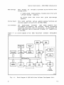
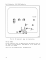
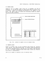
Figure 1-1 is a block diagram of the
Unit.
8560
Multi-User
Software
Development
Front
Panel
Flexible Disc
Drive
Hard Disc
Drive
r--------,
I
I
I
I
I
I
I
I
I
I
I
I
I
I
I
Line
Printer
L ______
I
I
I
.J
8560 System Bus
lOP
Board 2
lOP
Board 1
lOA
Board
To 8540s
or Terminals
3899-2
Fig. 1-1.
@
Block Diagram of 8560 Multi-User Software Development Unit.
1-3
General Description - 8560 MUSDU Installation
8560 MUSDU Backplane
The 8560 backplane carries the LSI-11/23 processor's Q-bus to all the circuit
boards in the MUSDU, and also provides the necessary interconnections between
circuit boards and any I/O devices in the system.
I/O signals are
distributed between the circuit boards and the I/O destination by the
backplane. Therefore, each circuit board that processes I/O functions is
assigned a dedicated slot in the backplane.
LSI-11/23 Processor
The Digital Equipment Corporation's LSI-11/23 microcomputer is the 8560's
main controller. The LSI-11/23 is contained on one dual-height, multi-layer,
plug-in circuit board (DEC M8186). The LSI-11/23 includes such features as:
•
Asynchronous bus operation, which allows the processor and system
components to run at their highest possible speed.
•
Memory management for 128K bytes of multi-user program space.
•
16-bit word or 8-bit byte addressable locations
•
Direct Memory Access (DMA) to allow peripheral devices to access
memory without interrupting processor operation.
System Memory
The 8560's System Memory is a
RAM.
A second 64K-word RAM
capacity. Each board contains
configured as either the upper
stand-alone, single-board, 64K-word dynamic
board may be installed to expand system memory
a jumper option to allow the board to be
or lower 64K bank of LSI-11/23 memory.
Mass Storage
To provide the large amount of peripheral mass storage required, one flexible
disc drive and one 8-inch hard disc drive are used in the 8560 MUSDU. The
flexible disc drive provides apprOXimately 1.2M bytes of formatted capacity
on a double-sided, double density, 8-inch disc. Either single density or
double density read/write format may be selected. Primary mass storage for
the 8560 MUSDU is provided by a Winchester-technology, fixed hard-disc drive
which provides appproximately 35.6M bytes of formatted capacity.
1-4
@
General Description- 8560 MUSDU Installation
PMS Controller
The PMS Controller board operates both mass storage drive units. However, in
order to interface the PMS Controller with the hard disc drive, an auxiliary
circuit board, the Micropolis 1220 Interface Card (M1220IFC) is installed
piggy-back on the PMS Controller board.
The PMS Controller uses a Z80A microprocessor with 8K of ROM and 1K of RAM,
to control all its hardware and software functions. An additional 8K of ROM
is provided on the M1220IFC board. The PMS Controller provides the interface
between the LSI-11/23 System Memory and the selected mass storage device. It
also assigns I/O output lines, and controls memory mapping functions, monitor
status, and error indications.
The M1220IFC board assumes control
of
the
PMS
Controller's
Z80A
microprocessor bus when data is being transferred between the LSI-11/23's
Main Memory and the hard-disc memory.
Utility Board
The Utility board provides support for functions not supported by other
boards in the 8560 MUSDU. Features supplied by the Utility board include:
•
Two RS-232-C interface ports
•
LSI-11/23 Line-Time Clock (LTC) function
•
Bootstrap ROM
•
Debug ROM
•
Front Panel functions (RESTART, RUN/HALT)
•
Bus termination resistors
•
LSI-11/23 power up/down sequencing
I/O Processor
The I/O Processor (lOP) is a single board that provides four full-duplex,
serial-interface channels. In the standard configuration, one I/O Processor
board is installed in the 8560 MUSDU. An optional second I/O Processor may
be installed to increase the 8560's I/O capabilities.
The lOP uses memory queues in the system memory to communicate with the
LSI-11/23.
The lOP provides I/O processing capability that would otherwise
be assigned to the LSI-11/23.
@
1-5
General Description - 8560 MUSDU Installation
Communications Adapters
Two small circuit boards are used in the interface between the IIO
and external devices:
Processor
•
The IIO Adapter (lOA) board permits selection of either RS-422 or
RS-232-C protocol for the HSI IIO ports, and performs the necessary
translation to RS-422 or RS-232-C compatible voltage levels.
•
All IIO connectors are mounted on the IIO Connector (laC) board,
located on the rear panel of the 8560 mainframe. In addition to the
eight (four optional) HSI IIO connectors, there are two dedicated
RS-232-C connectors for interface with line printers.
PERIPHERAL EQUIPMENT
In addition to the one or more 8540 Integration Units used with the 8560, the
8560 MUSDU will accommodate the following peripheral devices:
1-6
•
A system terminal may be connected to any vacant HSI IIO port that
has been configured for RS-232-C operation. A system terminal can
also be connected to an 8540 Integration Unit that is attached to
the 8560 MUSDU.
•
High-speed line printers may be connected to either of the two
pr inter ports.
line
@
General Description - 8560 MUSDU Installation
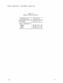
SPECIFICATIONS
Table 1-1
Electrical Characteristics
Supplemental
Information
Per formanc e
Requirement
Characteristic
------------------- ---------------------- ------------------------Suppl Y Vol tage
115 Vac Nominal
(90--132 Vac) or
230 Vac Nominal
(180--250 Vac)
-------------------+----------------------:------------------------Line Frequency
:
: 48 to 66 Hz
-------------------+----------------------:------------------------Line Current
: 8 Amps (max) at 115 Vac
:
: 4 Amps (max) at 230 Vac
-------------------+----------------------:------------------------Power Dissipation :
: 430 Watts (max)
Table 1-2
Environmental Characteristics
Characteristic
Description
===================:============================================
Temperature
Operating
Storage
I
I
: 10° C to 40 0 C (50° F to 104° F)
: _10 0 C to 65 0 C (14 0 F to 149 0 F)
-------------------+-------------------------------------------Humidity
:
Operating
Storage
: 20% to 80% relative non-condensing
: 8% to 90% relative non-condensing
-------------------+-------------------------------------------Altitude
:
Operating
Storage
: 2 500 m (8,000 ft) maximum (a)
: 15 000 m (50,000 ft) maximum
(a) Derate maximum operating temperature by 1° C for each 300 m
above 2 400 m.
@
1-7
General Description - 8560 MUSDU Installation
Table 1-3
Physical Characteristics
Characteristic
Description
--------------------- ------------------
1-8
Net Weight
34 kg (75 lb)
Overall Dimensions
Height
Width
Depth
267 mm (10.5 in)
432 mm (17.0 in)
597 mm (23.5 in)
@
8560 MUSDU Installation
Section 2
UNPACKING YOUR 8560 MUSDU
INTRODUCTION
This section discusses the steps to follow when unpacking and
8560 MUSDU. The following subj ects are covered:
installing
•
Site preparation, including space and power requirements.
•
Unpacking the 8560, including storage and reshipment.
•
Preparing the 8560 for operation.
an
SITE PREPARATION
The first consideration in selecting a suitable installation site is space.
Two other important criteria that must be considered are power requirements
and environmental conditions. These factors are discussed in the following
paragraphs.
SPACE REQUIREMENTS
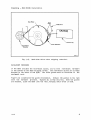
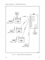
Dimensions of the 8560 MUSDU are shown in Fig. 2-1.
Here are some of the things you should consider when setting up an 8560:
@
•
Adequate clearance
Fig. 2-2).
must be allowed for ventilation of the 8560 (see
•
Clearance must
cable dress.
allowed at the rear of the unit to permit proper
•
Space may be required
system terminal.
•
Desk space may be required near the system terminal for reference
documents and other papers.
be
for
one or two line printers and perhaps a
2-1
Unpacking - 8560 MUSDU Installation
r-S97mmI23,S"l
Top View
533mm(21")~
Clearance Required
to Remove
t--
Top Panel
Slides to Rear
Side View
t1
JJ
r--
432mm 117"l
Rear View
i
D·
iI;J
u
-.
-Blr
u
(2974-5)3899-3
Fig. 2-1.
2-2
Dimensions of the 8560 MUSDU.
@
Unpacking - 8560 MUSDU Installation
~
'illllElE
Power
Supply
Fan
,-=
Disc Drives
Direction of
Air Flow
~
I---
tJ
jJ
~t'-
J1
LL-LJ
LLlJ
-u
Circuit
Boards
~
\--------,
g
~
B
I
..
~
~
'-
(2975-11 )3899-4
Fig. 2-2.
Air flow through the 8560 MUSDU.
Maintenance Access
You will need to gain access to the inside of
troubleshooting.
@
the
8560
for
servicing
and
•
Be sure to allow adequate space behind the unit to permit removal of
the sliding top cover and side panels. (If sufficient space behind
the unit is not available, it will be necessary to turn the unit
around, or remove it from the installation site, to remove the top
cover and side panel s.)
••
Allow adequate clearance above the 8560 to permit inspection and
removal of circuit boards, as shown in Fig. 2-3.
2-3
Unpacking - 8560 MUSDU Installation
610mm(24")
r
229mm(9")
Clearance
Required to
Remove
Typical P.C. Board
1~~~
I--
I--
h
u
(2975-11 )3899-5
Fig. 2-3.
2-4
Circuit board clearance requirements.
@
Unpacking - 8560 MUSDU Installation
POWER REQUIREMENTS
Primary power requirements for the 8560 MUSDU are as follows:
Line Voltage
115 Vac Nominal (90--132 Vac)
or
230 Vac Nominal (180--250 Vac)
Line Frequency
48 to 66 Hz
Line Current
8 Amps (maximum) @ 115V
4 Amps (maximum) @ 230V
Power Dissipation
430 Watts (maximum)
When preparing
guidel ines:
the
site
for
the
8560,
observe the following electrical
1.
Any peripheral components installed in the area must share common
ground and neutral lines to avoid noisy grounds and ground loops.
2.
All units must be properl y grounded.
3.
Power for the installation site
circui t breaker.
should
be
on
a
separate
service
ENVIRONMENTAL CONSIDERATIONS
The following considerations should be taken into account when preparing
installation site:
•
the
The area selected for the 8560 installation should be air-conditioned
and dust-free.
~
Static discharge may damage components of the 8560. Follow
standard anti-static procedures when installing an 8560
MUSDU.
@
•
The area should be as static-free as possible. If carpet is used,
the carpet must be static-free and treated with anti-static chemicals
as often as required.
•
The 8560 should be installed on a static-free work surface.
•
At least 6 inches' clearance must be maintained at the rear of the
8560 to allow adequate air circulation.
2-5
Unpacking - 8560 MUSDU Installation
UNPACKING THE 8560
If
Before you unpack the 8560, examine the carton for external damage.
damage is detected:
any
•
Immediately notify the carrier who delivered the 8560, and request an
inspection.
•
Contact your nearest Tektronix
representative.
•
Do not throwaway any cartons or other shipping materials.
•
DO NOT ATTEMPT TO REPAIR THE INSTRUMENT.
Field
Engineering
Office
or
sales
~
The hard-disc drive in the 8560 can be severely damaged by
excessive rough handling of the 8560. Exercise reasonable care
when lifting or moving your 8560 MUSDU. DO NOT DROP the unit onto
the bench top or other surface after it has been removed from its
shipping carton.
REMOVING THE 8560 FROM THE CARTON
The 8560 MUSDU is packed in a heavy-duty cardboard container, surrounded by
foam packing material. Inside the container, a piece of cardboard covers the
top of the uni t. The power cord and any options rest on this cardboard.
When you open the carton, remove the power cord and any other material that
may be on the cardboard, and set these items aside. Remove the cardboardd
and set it aside.
I WARNING
I
Be careful when lifting the 8560 out of the carton.
The
weighs 34 kg (75 lb). Don't hurt yourself - get some help.
8560
Remove the 8560 and surrounding foam. Set the packing material aside. Don't
lose this packing material - you'll need it again if you ever need to ship
the 8560.
2-6
@
Unpacking - 8560 MUSDU Installation
STORAGE AND RESHIPMENT
When a precision electronic instrument, such as the 8560, is to be placed in
storage or reshipped, it's best to repack it as it was originally shipped
from the factory. For this reason, you should save the carton and packing
material in which your 8560 was shipped. To repack the 8560, simply reverse
the unpacking instructions.
The following paragraphs describe further
considerations that pertain to storage or reshipment of your 8560.
Head Locking Device
To minimize the possibility of damage to the read/write heads during storage
and reshipment, a head-locking device is provided on the hard-disc drive
assembly. This device must be set to the "LOCK" position before the 8560 is
packed for storage or reshipment. Refer to the procedure, "Releasing the
Read/Write Head Shipping Lock", later in this section, for information on how
to access the locking device.
Storage
Observe the following considerations whenever you place the 8560 in storage:
•
Provide adequate protection from dust.
•
Do not exceed the humidity or temperature limitations of the
instrument.
(These limitations are listed in the Specifications, in
Section 1 of this manual.)
•
Store the carton upright.
objects on top of it.
Do not compress the carton or stack heavy
Reshipment
If the 8560 must be shipped to the factory or service center,
steps should be taken:
@
the
following
•
Note the serial number of the unit on the back panel and any other
(This
relevant
numbers or symbols needed for identification.
information is required for any related correspondence, which should
be sent separately.)
•
Wrap the unit in durable waterproof material such
as
heavy
polyethylene, and tape securely. This step should be performed only
in a dry atmosphere, and only when the unit is cool to the touch.
•
Pack the unit in a sturdy box (heavy cardboard is acceptable for land
shipment) t lined with 76 mm (3 in) of medium density foam or expanded
pol ystyrene.
2-7
Unpacking - 8560 MUSDU Installation
•
Cables, adapter s, and other accessories should be wrapped separately
and attached by tape to the inner liner at a break in the foam, or
taped to a separate platform mounted above the foam or polystyrene
(as used in the original shipping package). In the latter case, a
sheet of 25 mm (1 in) minimum thick foam should be taped above the
cable package.
•
Seal the carton with reinforced packaging tape and identify the
sender, the unit number, and the serial number on the outside of the
carton.
•
Notify the factory or your sales representative of your intent to
ship the instrument, and await their acknowledgement before you
actually ship your 8560.
PREPARING YOUR 8560 FOR OPERATION
After removing the 8560
surface, preferably the
the outside of the 8560
shipment.
If damage
section.
MUSDU from its shipping carton, set it on a flat
site you have selected for the installation. Examine
for any damage that may have been incurred during
is found, follow the procedures given earlier in this
Inside the 8560, an aluminum circuit board restrainer covers the circuit
boards that are installed in the card cage. This restrainer holds the
circuit boards securely in place during shipment. The following steps tell
how to remove the 8560 MUSDU top cover and the circuit board restrainer:
1•
you.
Remove
Slide the top
Turn the 8560 around so that the rear panel is facing
the two upper cover retainers, as shown in Fig. 2-4.
cover back and off the 8560 cabinet.
Examine the inside of the 8560 for any loose circuit boards or other
components, cables, or connectors. If any damage is apparent, follow
procedures given earlier for reporting damage.
~
In the following step you will remove small machine screws from the
inside of the 8560.
Do not drop these screws into the 8560.
Severe electrical damage can result if these items are left inside
the unit.
2-8
2.
Using a Phillips screwdriver, loosen the
(either end) of the restrainer assembly.
two
screws
3.
Remove the two screws on the other end of the
carefully remove the retainer clip (see Fig. 2-5).
on
one
end
restrainer
and
Unpacking - 8560 MUSDU Installation
Top Cover
~--~
~,~cover
Retainers
Cover Retainer
screws
1"1t"j----_ _
.. ~/
----+11+--___
~~
V
(3665-6)3899-6
Fig. 2-4.
Removing the 8560 MUSDU top cover.
Circuit Board
Restrainer
Remove these screws
Loosen these screws
(2974-7)3899-7
Fig. 2-5.
@
Removing the 8560 circuit board restrainer.
2-9
Unpacking - 8560 MUSDU Installation
4.
Remove the restrainer from the 8560 card cage.
NOTE
It is not necessary to replace the circuit board restrainer in
8560 unless the 8560 is to be stored or shipped.
the
5.
Reassemble the circuit board restrainer and store it with the packing
materials, for use in case the unit is stored or shipped.
6.
Do not replace the top cover at this time.
Installing Options
Information concerning the installation of
Installation Manual for the specific option.
options
is
provided
in
the
Releasing the Read/Write Head Shipping Lock
The read/write heads in the hard-disc drive unit are locked in place for
protection during shipment. The locking device must be released before power
is applied to the 8560 MUSDU.
1.
Remove the two lower cover retainers (refer back to Fig. 2-4).
remove both side panels.
2.
Remove all of the circuit boards from the card cage.
3.
Using a Phillips screwdriver, remove the three mounting screws on the
outside of the hard-disc drive, and the front inside screw. Refer to
Fig. 2-6.
4.
Using a stubby Phillips screwdriver, remove the two inside screws
that are accessible through the card cage.
5.
At the rear of the unit, disconnect the power cable and the M1223-1
interface cable.
6.
Close the door on the flexible disc drive.
7.
Lift the hard-disc drive slightly, then carefully slide it out, about
3 inches, through the front-panel opening in the cabinet.
2-10
Then
@
Unpacking - 8560 MUSDU Installation
8.
The nylon locking device is located on the bottom of the disc-drive
unit, near the front of the assembly.
Using the special tool
provided, or an equivalent wide-bladed tool, turn the screw 90
degrees clockwise, to the UNLOCK position.
9.
Carefully
slide
the unit back into the cabinet through the
front-panel opening until the front panel of the hard-disc drive unit
is aligned with the front panel of the flexible disc unit.
10.
Install the six mounting screws removed in steps 3 and 4.
11.
Connect the power and interface cables to the unit.
12.
Install all circuit boards that were removed earlier. Be sure that
circuit boards are returned to their original slots in the card cage.
13.
Install the side covers and the two lower cover retainers.
Tighten
the retainer screws securely. Do not install the top cover at this
time.
Front inside
screw
3899-8
Fig. 2-6.
@
Removing the hard-disc drive unit.
2-11
Unpacking - 8560 MUSDU Installation
Removing the Hard-Disc Rotor Restraint
Movement of the disc rotor in the hard-disc drive unit during shipment is
prevented by a rubber shipping restraint. This restraint and its associated
caution tag must be removed before power is applied to the 8560 MUSDU.
1•
Using a flat-blade screwdriver, loosen the three captive retaining
screws on the hinged Driver Interface board (see Fig. 2-7) •
2.
Swing the hinged board
rotor ( see Fig. 2-3) .
3.
Carefully untwist the tie wire and remove the caution tag from the
disc brake arm (see Fig. 2-8).
4.
Remove the rubber shipping restraint.
packing materials.
up
to allow access to the hard-disc drive
Store this restraint with the
NOTE
The rubber shipping restraint must be installed on the disc
rotor anytime the 8560 MUSDU is shipped or stored.
5.
Lower the hinged board to its normal position, then tighten the three
captive screws.
6.
Install the top cover and the two upper cover retainers.
retainer screws securely.
Tighten the
Head Restraint
To prevent damage to the read/write heads in the flexible-disc drive
assembly, a cardboard head restraint is installed in the disc slot during
shipment or storage of the 8560 MUSDU. Before you operate the 8560, remove
this restraint; pull outward on the cardboard tab that protrudes through the
front panel of the flexible-disc drive unit.
Store the cardboard head
restraint with the other packing materials, for use in case the unit is
stored or shipped.
2-12
@
Unpacking - 8560 MUSDU Installation
~ ~ ~::,"\
"
,:':
\
'v
\
\
\
\
\
1
,
\
____ Board in
Raised Position
\~
\
\
\
\
\
\
\
\
\\
\
"
\
\
\
\
Captive Retaining
Screws (3)
Hinged Driver
I nterface Board
3899-9
Fig. 2-7.
@
Location of Driver Interface board retaining screws.
2-13
Unpacking - 8560 MUSDU Installation
Disc Rotor
CAUTION
3899-10
Fig. 2-8.
Hard-disc drive rotor shipping restraint.
RACK-MOUNT PROCEDURE
If the 8560 includes the rack-mount option, you'll find rack-mount hardware
in the bottom of the 8560 shipping carton. The rack-mount slides are already
mounted to the sides of the 8560. The slide guides must be installed in the
equipment rack.
Figure 2-9 illustrates the guide orientation. Install the guides in the rack
with th~ hardware provided. Tighten all screws securely. When the guides
are mounted, slide the 8560 into the rack, keeping cable dress in mind.
2-14
@
Unpacking - 8560 MUSDU Installation
CJ
CJ
()
()
CJ
0
r:b::
tll@
trll(@
~
()
()
(2974-8)3899-11
Fig. 2-9.
Rack-mount guide orientation.
SELECTING THE PROPER PRIMARY VOLTAGE
Each 8560 has been configured to connect to the primary power source
available at its installation site. If, for any reason, it becomes necessary
to change to a different power source, use the following procedure to adapt
the 8560 to the new input power.
1.
Refer to Fig. 2-10. Notice the small plate at the lower left part of
the rear panel (as you face the rear of the uni t) . Remove the screw
holding this plate.
2.
The power range selector switch is located under the plate. This
switch selects operation at either 115 or 230 volts (nominal), as
marked. Set the switch to the correct primary power range.
~
The fuse rating depend s on the primar y power source being used.
For 115-Volt operation, use a 3AG, 8 A, 250 V, fast-blow fuse. For
230-Volt operation, use a 3AG, 4 A, 250 V, fast-blow fuse.
The
proper fuse must be used.
@
2-15
Unpacking - 8560 MUSDU Installation
3.
Install a fuse with the proper rating into the line fuse holder.
4.
Replace the switch cover plate so
indicated.
that
the
new
voltage
range
is
o
Remove this screw
o
Range Selector Switch is
under this indicator plate
3899-12
Fig. 2-10.
2-16
Selecting the primary power voltage range.
@
8560 MUSDU Installation
Section 3
8560 MUSDU VERIFICATION
INTRODUCTION
At this point, you have unpacked the 8560 MUSDU and verified that it is
properly configured for the available primary power source. This section
tells you how to verify the operation of the 8560.
To perform this
verification, you will need a system terminal. Instructions for attaching a
TEKTRONIX 8540 Integration Unit and a line printer are also included in this
section.
This section is divided into three parts:
•
The first part helps you locate and identify the various controls,
connectors, and indicators on the front and rear panels.
•
The second part tells you how to set up the 8560 MUSDU for operation
and how to attach a system terminal, an 8540 Integration Unit, and a
line printer to the 8560.
•
The third part describes how to run
the
diagnostic
tests.
Diagnostics used for this verification are intended only to establish
that the 8560 will power up and run selected basic diagnostic tests
satisfactorily.
To verify that the 8560 will perform all its
operating functions, refer to the complete diagnostic test program,
described in the optional 8560 Multi-User Software Development Unit
Service Manual.
CONTROLS, CONNECTORS, AND INDICATORS
The following paragraphs describe briefly the controls, connectors, and
indicators on the front and rear panels of the 8560 Multi-User Software
Development Unit.
FRONT PANEL CONTROLS AND INDICATORS
There are three switches on the 8560 front panel: the DC ON/OFF switch, the
system RESTART switch, and the RUN/HALT switch.
There are also three
indicators on the front panel: DC ON, AC ON, and PROCESSOR BUSY. Front panel
controls and indicators are identified in Fig. 3-1.
@
3-1
Verification - 8560 MUSDU Installation
DC ON/OFF
\
~ ~ ~ ~ ~ ~ ~ 1\ ~ ~ ~ ~ ~ ~
/ Ready Light
,~ ~ ~ ~
I tUN
ACON-
DCON\
/HALT
I
-1
I
@
I
I
III
Ilf
I
II
~
'R!ktronix ............
RESTART
I
........
@
....,
~
li~
~
T
ov"
~~ ~~ ~~~~.
J
I
............
U
~
,,,OJ
~ Access Lig ht
L
PROCESSOR
BUSY
U
3899-13
Fig. 3-1.
8560 MUSDU Front Panel Controls and Indicators.
DC ON/OFF Switch
This two-position rocker
circui ts.
switch
controls
dc
power
to
the
8560's
logic
DC ON Indicator
The DC ON indicator illuminates when +5 Vdc power is present in the 8560.
RESTART Switch
This switch is a two-position, spring-return toggle switch. When the RESTART
switch is toggled upward, the 8560 MUSDU will either halt or re-boot,
depending on internal board configuration and the position of the RUN/HALT
switch.
3-2
@
Verification - 8560 MUSDU Installation
RUN /HALT Swi tch
The RUN/HALT switch selects the 8560 operating mode: RUN for normal program
execution, HALT for special operations controlled by peripheral devices. For
additional information about the RUN/HALT switch, refer to your 8560 MUSDU
System Users Manual.
AC ON Ind icator
This indicator illuminates whenever the rear panel POWER switch is in the
posi tion and primary ac power is applied to the 8560.
ON
PROCESSOR BUSY
The PROCESSOR BUSY indicator is normally illuminated
during
program
execution, but is off when the processor is halted, or waiting for an
interrupt after executing a Wait for Interrupt (WAI) command.
REAR PANEL CONTROLS AND CONNECTORS
The rear panel contains primary power components and all I/O interface
connectors. Rear panel controls and connectors are identified in Fig. 3-2.
Power Cord Receptacle
The line cord connects to this receptacle to supply primary ac power
8560.
to
the
~
Connect the line cord only to the line
voltage selector switch cover plate.
voltage
indicated
voltage
selector
on
the
Line Fuse
Use only a fuse rated as indicated
plate:
@
on
the
switch
cover
•
For 115 Vac operation, use a 3AG, 8 Amp, 250 Volt, fast-blow fuse.
•
For 230 Vac operation, use a 3AG, 4 Amp, 250 Volt, fast-blow fuse.
3-3
Verification - 8560 MUSDU Installation
I.
~iw1~~~~~r~·~i;
D
.1 g
0
I
o
HSI I/O Ports
0-7
@
~-=-@_-_-_-_-_-_-_-_-_-_-_-,_o_@_ _ _ _ _ _
@-d@
o
flr
oO&J1?
I.
o
-@~-@~@
-~@-'@~@
@~@-@~(f)
Power
Switch
Line Fuse
-(f)~(f)-@~(f)
Line Printer --H~-@~@ ~;@~@
Ports
o
Power cord
Receptacle
Disc Extender Port
Primary Voltage
Indicator Plate
3899-14
Fig. 3-2.
8560 Rear Panel Controls and Connectors.
Primary Voltage Selector Switch
The voltage range of the primary power source for the 8560 is selected with
this switch.
A cover plate over the switch indicates which of the two
possible voltage ranges is selected: 90--132 Vac or 180--250 Vac.
~
If you change the primary voltage range, be sure to change the line
fuse to the value indicated on the reinstalled cover plate.
3-4
@
Verification - 8560 MUSDU Installation
POWER Swi tch
This two-position rocker switch controls input ac power to the 8560 MUSDU.
When primary power is applied and the POWER switch is ON, the AC ON indicator
on the front panel will be illuminated.
HSI IIO Ports 0--7
These ports are normally configured for RS-422 High-Speed Interface with 8540
Integration Units.
Any of ports 0--7 may be reconfigured to RS-232-C
protocol with internal jumpers.
NOTE
Standard equipment configuration includes only ports
4--7 are optional.
0--3.
Ports
Line Printer Ports 1 and 2
These are dedicated RS-232-C IIO ports for attaching
8560 MUSDU.
line
printers
to
the
8560 SET-UP
Verify that the power input range switch is set to the proper primary
voltage, then plug the power cable into the correct primary power source.
ATTACHING A SYSTEM TERMINAL
Any of the HSI IIO connectors may be used as a direct interface to a system
terminal.
However, the HSI IIO port to be used must be configured for
RS-232-C protocol. To set the internal jumpers for RS~232-C operation:
1.
Turn the 8560 around so that the reear panel is facing you. Remove
the two upper cover retainers, then slide the top cover back and off
the 8560 cabinet.
2.
On the IIO Adapter board, locate the jumper for the HSI IIO
be used for your system terminal. Refer to Fig. 3-3.
3.
Move the jumper to its lower position.
4.
Install the top cover and top cover retainers.
port
to
Now connect the RS-232-C cable from the system terminal to the selected
interface connector on the 8560 rear panel. Refer to Fig. 3-2 for connector
locations.
@
3-5
Verification - 8560 MUSDU Installation
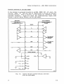
HSI 1/0 Port Specifications
Each HSI 1/0 port is a 25-pin female connector. The normal configuration for
these ports supports a modified RS-422 High-Speed Interface (HSI).
NOTE
The connectors for HSI 1/0 ports 0--7, while designed to support
either RS-232-C or RS-422 signals, do not conform to the EIA RS-422
pinout specification.
As discussed earlier, any HSI 1/0 port may be reconfigured for RS-232-C
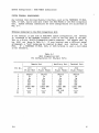
protocol. Table 3-1 describes the interface connector pin assignments.
In
the RS-232-C configuration, only the positive side of the balanced signals is
used. Jumpers for selecting the interface are located on the 1/0 Adapter
board. Refer to the table in Fig. 3-3 for identification of these jumpers.
Table 3-1
User-Selectable Interface Connector
Pin Assignments
Pin No.
Description
Symbol
Comments
----------------- ----------------------------------------- ---------- ----------------------------------------------1
7
2
11
3
12
20
13
5
25
6
18
8
9
3-6
Shield
Signal Ground
Transmit Data
Transmit Data
Receive Data
Receive Data
Data Track Ready
Data Track Ready
Clear to Send
Clear to Send
Data Set Ready
Data Set Ready
Carrier Detect
Carrier Detect
Tx
Tx'
Rx
Rx'
DTR
DTR'
CTS
CTS'
DSR
DSR'
DCD
DCD'
Data received by
8560 MUSDU
Data transmitted by
8560 MUSDU
Always
Always
Always
Always
transmitted
transmitted
transmitted
transmitted
On
On
On
On
@
Verification - 8560 MUSDU Installation
Jumper in RS-232-C (SIO) Position
Jumper in RS-422 (HSI) Position
HOOOOOO
.... ........ ........ ........ ........ ........ ........ ........
....
0
0
0
0
0 0
0
0
00 ,... CD It) q- (W) N
-, -, -, -, ., -, -, ....
-,
Jumper
Connector
HSII/O Port
J1011
J2011
J3011
J4011
J5011
J6011
J7011
J8011
J801
J802
J803
J804
J806
J807
J808
J809
0
1
2
3
4
5
6
7
3899-15
Fig. 3-3.
Location of jumpers on the IIO Adapter board.
ATTACHING AN 8540 INTEGRATION UNIT
To attach an 8540 Integration Unit to the 8560 MUSDU, connect an RS-422 cable
between the HSI port (J100) on the 8540 rear panel, and one of the HSI IIO
ports on the 8560 rear panel.
NOTE
For use with an 8540 Integration Unit, the 8560 HSI IIO
be configured for RS-422 protocol.
@
port
must
3-7
Verification - 8560 MUSDU Installation
ATTACHING A LINE PRINTER
A line printer with standard RS-232-C interface protocol may be connected to
either of the two Line Printer connectors on the rear panel of the 8560
MUSDU.
RS-232-C Port Specification
Each RS-232-C Line Printer port is a 25-pin female connector.
These two
dedicated ports are normally configured for RS-232-C protocol for line
printer interface.
NOTE
The line printer ports are
2400. If a different baud
be reconfigured. Refer to
about setting line printer
preset at the factory for a baud rate of
rate is required, the Utility board must
Section 4 of this manual for information
port baud rates.
Table 3-2 lists pin assignments for the RS-232-C line printer connectors.
Pin assignment for these connectors is derived from the EIS RS-232-C pinout
specification.
Table 3-2,
RS-232-C Interface Connector
Pin Assignments
Pin No. l
Description
Symbol
Comments
=========1======================
=========1=======================
Protective Ground
1
2
3
4
5
6
7
8
15, 17
20
3-8
Transmit Data
Receive Data
Request to Send
Clear to Send
Data Set Ready
Signal Ground
Data Carrier Detect
External Clock
Data Terminal Ready
Tx
Rx
RTS
CTS
DSR
Data received by 8560
Data sent by 8560
DCD
Always transmitted ON
Always transmitted ON
DTR
@
Verification - 8560 MUSDU Installation
VERIFICATION
The 8560 MUSDU is now ready for operation. The remainder of this section
describes the power-up procedure for the 8560, and how to verify system
operation using the disc-based diagnostics.
Two levels of diagnostics are used to verify operation of the 8560: ROM-based
and disc-based.
The ROM-based diagnostics are run automatically each time
the unit is powered up or reset. The disc-based diagnostics are contained on
a separate flexible disc, and can be run only when they have been loaded into
the 8560. Components of the 8560 that are tested by diagnostics are listed
below, in the order tested:
RAM
ROM
LSI-11/23 CPU
Line Time Clock
Line Printer Ports
I/O Processor
PMS Controller
Before beginning the 8560 power-up procedure, turn on the system terminal and
allow it to warm up.
POWER-UP PROCEDURE
The primary power switch is located on the rear panel of the 8560 MUSDU. The
DC ON/OFF switch is located on the front panel. Refer to Figures 3-1 and
3-2.
When the terminal is warmed up, perform the following procedure:
1.
Turn on the POWER
will illuminate.
switch.
The AC ON indicator on the front panel
2.
Move the DC ON/OFF switch to the ON position.
PROCESSOR BUSY indicators will be illuminated.
The DC ON iand
After dc power has been applied for approximately 30 seconds, the LED on the
hard-disc drive will illuminate, indicating that the hard-disc drive is at
operating speed.
If the PROCESSOR BUSY light goes out completely, or if an error message is
displayed on an installed terminal or line printer, the 8560's internal
ROM-based power-up diagnostics have detected a fault in the unit.
Refer to
the optional 8560 Multi-User Software Development Unit Service Manual for
troubleshooting procedures. For more information about troubleshooting your
8560 MUSDU, contact your local Tektronix Service Center.
3~
Verification - 8560 MUSDU Installation
SYSTEM VERIFICATION PROCEDURE
When you have successfully completed the power-up procedure, you're ready to
run the 8560 disc-based diagnostics. The following information provides only
a procedure to verify system operation; it is not intended as a detailed
description of the 8560 diagnostics.
Perform the following procedure to verify system operation:
1.
Insert the 8560 System Diagnostics
8560's flexible disc drive.
2.
Close the door on the disc drive.
3.
Toggle the RESET switch.
~.
Within
disc.
5.
The system terminal will display the following information:
20
seconds,
the
8560
disc (label side up) into the
will begin a preliminary read of the
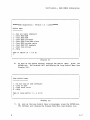
8560 DIAGNOSTIC DISC V x.x
NOTE
This message is transmitted at the 2400 baud.
If your
terminal is not operating at 2400 baud, the message will
not be readable.
6.
If the terminal is not set for 2400 baud, press the BREAK key one or
more times until the following message is displayed:
NEW BAUD RATE SELECTED
7.
The 8560 will begin reading the disc again. Within 12 seconds, if
more than one system terminal is on-line, the terminal may display
the following information:
PRESS RETURN TO SELECT TERMINAL
9.
3-10
If this message appears, press the RETURN key. The 8560
will now display the Option Menu (see Display 3-1).
diagnostics
@
Verification - 8560 MUSDU Installation
******8560 Diagnostics - Version 1.0 - loaded******
option menu
-
0
1
2
3
4
5
6
7
H
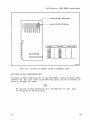
Run all tests [defaul t]
Test 8560 RAM
Test 8560 ROM
Test 8560 processor
Test 8560 line-time clock
Test 8560 pr inter ports
Test 8560 lOP channels
Test disc drives
Help
Type in option (0 - 7 or H)
?
Display 3-1
10.
As soon as the system terminal displays the Option Menu, press the
RETURN key. The terminal will now display the Loop Control Menu (see
Display 3-2).
Loop control menu
1
2
3
H
-
Do not loop on test [default]
Loop on test
Loop until error
Help
Type in loop control (1 - 3 or H)
?
Display 3-2
11.
As soon as the Loop Control Menu is displayed, press the RETURN key.
The terminal will display the Display Mode Menu (see Display 3-3).
3-11
Verification - 8560 MUSDU Installation
Display mode menu
1 - Display run-time status [default]
2 - No run-time display
H - Help
Type in mode (1 - 2 or H)
?
Display 3-3
12.
As soon as the Display Mode Menu is displayed, press the RETURN key.
The terminal will display the run-time status, then will display the
Display output Menu (see Display 3-4).
Display output menu
1 - Display on terminal [default]
2 - Display on printer 1
3 - Display on printer 2
H - Help
, Type in display output
?
(1 -
3 or H)
Display 3-4
13.
Press the RETURN key again and the diagnostics will begin to execute.
The 8560 disc-based diagnostics require about two minutes to execute.
end of that time, the system terminal will display either:
At the
8560 verification passed
or
8560 verification failed
3-12
@
Verification - 8560 MUSDU Installation
If the "8560 verification failed" message is displayed, the diagnostics
detected a fault in the 8560 MUSDU. In that case, refer to the optional 8560
Multi-User Software Development Unit Service Manual, or to your Tektronix
Service Center, for detailed diagnostic troubleshooting procedures.
This completes the 8560 MUSDU verification procedure.
@
3-13
8560 MUSDU Installation
Section 4
8560 MUSDU BOARD CONFIGURATION
INTRODUCTION
This section provides information about the various jumpers and straps
located on circuit boards in the 8560 MUSDU. Only those jumpers and straps
that specifically relate to installation or verification of the 8560 are
discussed in detail.
Other jumpers and straps are used primarily for
testing, and are described in detail in the optional 8560 Multi-User Software
Development Unit Service Manual.
JUMPERS AND STRAPS
The standard circuit boards for the 8560 MUSDU are configured for specified
operating characteristics with certain jumpers and straps. The following
paragraphs describe these jumpers and straps, and tell how to configure them
to select the desired circuit functions.
NOTE
All jumpers and straps on 8560 circuit boards are set at the
factory
for proper operating configuration.
However, before
applying power to the 8560, you should check the circuit boards to
verify that jumpers are correctly installed.
JUMPERS
A "jumper" consists of a set of jumper pins on a circuit board, and a jumper
block.
A jumper block normally bridges two adjacent square pins on the
circuit board. In certain applications, a larger jumper block may be used to
configure several sets of jumper pins simultaneously.
•
A single-position jumper station consists of
jumper block is either installed or removed.
•
A multi-position jumper station is made up of three or more pins,
arranged so that the jumper block may be installed in any of two or
more positions, or may be removed.
only
two
pins •
The
Jumpers are identified with "Jxxxx" reference numbers.
@
4-1
Board Configuration - 8560 MUSDU Installation
STRAPS
A "strap" is a wire (or specially designed circuit board run) that connects
one
through-hole
or circuit point on a circuit board with another
through-hole or cireui t point. Certain circui t board runs are designed to be
cut,
in
conjunction
with
strapping options, to achieve a desired
configuration. These are referred to as "cuttable runs".
Straps are identified wi th "Wxxxx" referenc"e numbers.
LSI-11/23 PROCESSOR
There are no user-definable jumpers, straps, or switches on the LSI-11/23
Processor board. To verify correct jumper configuration on this board, refer
to Fig. 4-1.
3899-16
Fig. 4-1.
4-2
Jumper configuration for the LSI-11/23 Processor board.
Board Configuration - 8560 MUSDU Installation
64K MEMORY BOARDS
The system memory in the 8560 MUSDU consists of either one or two 64K-word
dynamic RAM boards. If two RAM boards are used, one board supports the lower
64K words of memory and the second (optional) board supports the upper 64K
words.
Jumpers on the memory boards must be installed according to the
memory configuration in your system. Refer to Fig. 4-2 for locations of
jumpers and straps on the 64K RAM boards.
MEMORY RANGE SELECTION
If only one memory board is installed, jumper J6112 must be in the CA--CC
position.
This configuration assigns the lower 64K of memory addresses to
the board.
If two memory boards are used, jumper J6112 must be in the CA--CC on one
board (lower 64K), and in the CA--CB position on the other board (upper 64K).
IIO MEMORY
Jumper J5161 must be installed across pins CF--CG on the 64K RAM boards.
With the jumper installed at this location, 2K of the upper portion of memory
is assigned to IIO operations.
NOTE
Jumper J5161 must be properly installed
operating system to operate properly.
for
the
8560's
TNIX
4-3
Board Configuration - 8560 MUSDU Installation
+500GND
J5077
J5091
J5108
1881
I§§I
18BI
1881
J6078
-
CF CG
J 5161
- -
CBJ6112
o
CD CE
CACC
v
ex) 0')
C")
00
.... ...
~~
~~
.... ...
.......
BY BZ
_OJ7121
0000
CL CM
o
00 0000
~~
II
&nco
CK CL
....... J . . . . ------------'
oo
CJ C i o n Resistors
0000
J 6135
"'''1
......
J7088
......_ _ _ _ _ _ _ _ _ _ _ J7101 _ _ ~.~
J7141
CN
... ...
~ ~
3899-17
Fig. 4-2.
64K Memory board jumper and strap locations.
RAM TEST JUMPERS
With the exception of J6112, all jumpers on the 64K RAM board are preset at
the factory for normal operation. These jumpers are for test purposes only,
and should not be changed.
There are no user-definable straps on the 64K RAM boards.
4-4
@
Board Configuration - 8560 MUSDU Installation
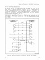
PMS CONTROLLER BOARD
The Head Unload Delay jumper (J1040) on the PMS Controller board must be
installed for proper operation of the flexible disc drive. The jumper is
preset at the factory in its normal (vertical) position, which enables a
delay of approximately three seconds in the head unloading sequence. With
the jumper in the horizontal position, this delay is omitted.
NOTE
If the delay is omitted, some chattering
observed during the head unload sequence.
r
I
of
the
head
will
be
-----------------------------------omN----------------------~
0)00)
010
T'8
TP1011D
J10311123
J1034
o
oJ1040
TP1012
_
~J1011
o
J2040
1111111111
J1010
o
TP3012
°
1111111111
J2110
o
J2130
1111111111
1111111111
J2111
J3020
I I I I I II II
J3070
J3080
~
TP1141D
TP1142D
0 TP1143D
0
J1131
0
J1130
J1038
- o
~~ ...~..,~~
_
J2131
-
TP3141D
o
J 3100
TP5051D
o TP5052
---
J5105
J5058
J6061
- -l
- - -8 ~6140
J5140~
o
o
J41401
J7101
0
o
J6062
J6121
o
o
J7102
0
J7115 0
J71030
o
J7116
g
J6122
0
J6123
11111111111
o
TP7012
II I I I I I I I
J7081
J7105
o
~
[
~--------~---
I
c..
I-
~ 0
..."o:t
-~
..,
~
c..
I-
3899-18
Fig. 4-3.
@
PMS Controller board jumper locations.
4~
Board Configuration - 8560 MUSDU Installation
All other jumpers on the PMS Controller board are preset at the factory for
normal system operation. These jumpers are for test purposes only, and
should
not
be
changed from their preset posi tions.
Normal jumper
configuration for the PMS Controller board is shown in Fig. 4-3.
M1220 INTERFACE CARD
All jumpers on the auxiliary M1220 Interface Card (IFC) are preset at the
factory for normal operation, and should not be changed. Figure 4-4 shows
normal jumper configuration for the M1220 IFC.
_
_
J1011
J1012
_
J1013
I
-
J1041
TP3050
0
J2011
-
0
TP3059
0
TP2014
a
a
J3045
TP2015
0
TP3045
I
J3011
---------
IJ4011
J5051 J5055
DO
DO
DO
0
TP6038
00
00
J6055
3899-19
Fig. 4-4.
4-6
M1220 Interface Card jumper locations.
Board Configuration - 8560 MUSDU Installation
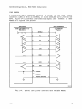
UTILITY BOARD
Figure 4-5 shows the locations of jumpers and straps on the Utility board.
J1036 _
Maintenance
Jumper
Interrupt
Vectors
BA
_.J2052
_.J2053
_
_ J2054
W1071 { : : } W1072
.-J2055
-.J2056
Framing Errors
"404'/46~
_ _ J3052
_ _ J3053
VV404'/42~~
.....-.
_ . J3054
_ _ J3055
_ _ J3056
W4043/44
. . A~
•
•
•
•
•
W1073 { : : } W1074
•
••
Parity
and Bits/
Char.
e----e
~
•
••
•
•
•
•
•
. . B ....
W3071 { : : } W3073
W1098
W1099
W2091
W2092
W2093
W2094
W2095
W2096
W2097
W2098
W3091
W3092
W4031/32
•
A ....
~
III:Il
W3072 { : :
Baud Rate
Enable
Printer 2
Port
Baud Rate
Selection
Baud
Enable
Printer 1
Port
} W3074
~}W4016/17
::-S=:} W4018/19
W5061
IO
ROM/LTC
Disable
W6101/02
Interface Address
Printer 2
Printer 1
B
.W.
Mode
6114 . _ . - 6134
7111 _
•_
•_
•
- 7131
7112
.7132
=--:} W7011 /12
- - - - : } W7013/14
L-:}
W7015/16
: - - : } W7017/18
·rn·
A B A
6111 . . .1i1iii16131
6112._ . _ 6132
6113 _ _ . _ 6133
Line
Printer
-
7113 • • • _ 7133
7114 _ _ . _ 7134
7115 _ •
•
_7135
7116. _ _ .7136
J7079
Power Up/Down
Control
f
(2975-17)3899-20
Fig. 4-5.
@
Utility board jumper and strap locations.
4-7
Board Configuration - 8560 MUSDU Installation
LINE PRINTER INTERFACE
Baud Rate Selection
The baud rate for the two dedicated RS-232-C Line Printer interfaces is
factory set at 2400 baud. If a different baud rate is required, strapping
options on the Utility board permit you to select of a specific baud rate.
The Utility board can also be configured to accept an external TTL-level
clock signal between 0 and 320 kHz (the external clock frequency is 16 times
the baud rate).
Table 4-1 lists the strapping options for baud rate
selection.
Table 4-1
Baud Rate Selection
----------------------------------------------------------------
, W2097 , W2098
---------------------------- -------,------- ------- Baud Rate
Inter~face 2 Straps - W2094
W2091
W2093 , W2092
------- -------------------------------------- =======:======= ------Interface 1 Straps - W2095
W2096
I
I
I
I
I
In
In
In
In
In
In
In
In
Out
Out
Out
Out
Out
Out
Out
Out
4-8
In
In
In
In
Out
Out
Out
Out
In
In
In
In
Out
Out
Out
Out
In
In
Out
Out
In
In
Out
Out
In
In
Out
Out
In
In
Out
Out
In
Out
In
Out
In
Out
In
Out
In
Out
In
Out
In
Out
In
Out
Ext. Clock
Ext. Clock
50
75
134.5
200
600
2400
9600
4800
1800
1200
2400
300
150
110
@
Board Configuration - 8560 MUSDU Installation
Interface Address Jumpers
Jumpers that define interface address words for the Line Printer ports are
installed at the factory in the proper configuration for normal operation.
These jumpers should be in the configuration shown in Fig. 4-5.
Interrupt Vector Address Jumpers
Jumpers that define interrupt vector address words for the Line Printer ports
are installed at the factory in the proper configuration for normal
operation. These jumpers should be in the configuration shown in Fig. 4-5.
DEBUG ROM CONTROL JUMPER
For normal system operation, jumper J1036 must be installed.
POWER UP/DOWN CONTROL JUMPER
For normal system operation, jumper J7079 must be installed.
STRAP CONFIGURATION
All straps on the Utility board are preset at the factory for normal system
operation and should not be altered. For information about these straps and
alternate
configurations,
contact
your
Tektronix
Field
Service
representative.
@
4-9
Board Configuration - 8560 MUSDU Installation
I/O PROCESSOR BOARD
The interface circui try in the 8560 MUSDU incl udes either one or two I/O
Processor (lOP) boards. One of these boards controls I/O functions through
HSI I/O ports 0--3, and the second board (optional) controls HSI I/O ports
4--7.
Figure 4-6 shows the jumpers on the lOP board posi tioned for normal
operation. Except for the jumpers discussed in the following paragraphs,
jumpers on the lOP board are preset at the factory and should not be changed.
ROM ..... ~RAM
BBB
OIJa:Da:oo:IJCDJCDJOIJCDJ[l]][l]]
II
OM
~OM
~OM
~OM
~OM
88~
"I I
Diagnostics
Display
ROM·
ROM
OR
RAM
OR
RAM
OR
RAM
OR
RAM
OR
RAM
RAM
RAM
Signature
Analysis {
J2172
J2173
c::.
J2061
B
J2041
RAM
,
a:IID
a:IID
aIm
J2174 a:IID
J2171
Device
Registers
J3161
1 0
A5
A4
r:.
r:.
J4051
J4052
A2
A1
C.
J4053
J5054 (Refer to text)
c:.
J3162
'.:J
J5161
~
J6091
...
~
o
5
~
tj
>
>
Q)
Q)
db db
-
[l]] OIJ
aD ITIJ
aD ITIJ
J7011
J6171
Interrupt Vectors
(Refer to Text)
f
3899-21
Fig. 4-6.
4-10
I/O Processor board jumper locations.
@
Board Configuration - 8560 MUSDU Installation
DEVICE REGISTERS
An 1/0 Processor board is designated as either lOP 1 or
lOP 2
by
configuration of the device register address jumpers. If only one lOP board
is is used in the 8560, it must be configured as lOP 1 and installed in the
lOP 1 slot in the 8560 card cage.
Figure 4-1a illustrates the jumper
configuration for lOP 1.
If your 8560 utilizes two lOP boards, one of these boards must be configured
as lOP 1 and installed in the lOP 1 slot, as above. The second board must be
configured as lOP 2 and installed in the lOP 2 slot in the card cage.
See
Fig. 4-1b.
A5
0
Il1~;li@;I:lmM;1
J4051
A5
0
l:j!1r;~::l!!:lt:K;:::ll
J4051
A4
0
li¥l~~t~Mlm:1
J4052
A4
0
Illtt.g:;;f!:;;:~m::1
J4052
A2
0
Itf:Miil;flj:l1;I;:I::I::;:1
J4053
A2
0
1:::::ili1~:::;:;I:Ir:;m;;;:m:1
J4053
A1
0
1~&M::n;::mlrl
J4054
A1
1::;:;::::I::::;iiI::i1;:ll @1
0
J4054
(a)
(b)
lOP Board 1
(Device Register Address 00)
lOP Board 2
(Device Register Address 01)
3899-22
Fig. 4-1.
Device Register jumper positions.
INTERRUPT VECTORS
Two independent interrupt vectors that interface with the LSI-11/23 Processor
board are generated on the lOP boards. The two interrupt vector circuits can
be independently jumpered to select a level of interrupt priority.
One set
of jumpers determines which interrupt lines will be asserted, and the other
set of jumpers selects which lines will be monitored, when intercepting a
grant from the LSI-11/23 Processor. Table 4-2 describes the various priority
levels. Figure 4-8 shows the jumper arrangement for Vectors 1 and 2, and
Fig. 4-9 illustrates jumper configurations for priority levels 4, 5, and 6.
Priority level
user-definable.
@
1
is
assigned
for
LSI-11/23
use
only
and
is
not
4-11
Board Configuration - 8560 MUSDU Installation
Table 4-2
Interrupt Priority Assignments
Interrupt
Lines Monitored
Interrupt
Lines Asserted
Priority
Level
---------- ------------------ -------------------------BIRQ
BIRQ
BIRQ
BIRQ
4
5
6
1
BIRQ 5, 6
BIRQ 6
BIRQ 1
4
4, 5
4, 6
4, 6, 1
Vector 1
Vector 2
0
0
J7121
0
0
0
J7125
0
0
0
J7122
0
0
0
J7126
0
0
0
J7123
0
0
0
J7127
0
0
0
J7124
0
0
0
J7128
0
0
0
3899-23
Fig. 4-8.
Interrupt Priority jumper arrangement.
o
o
J7121 I J7125
liiiII::1 0
J71221 J7126
l:i:iII:::1 0
J71231 J7127
0
I Ii:1
liIII 0
o I: IiI.1
o l:i:Ii:III
o 1:.... I;1
J71241 J71 28
0
I:II
o IIIII
1 .. :..:1
1.1 0
(a)
(b)
(c)
Level 4
Level 5
Level 6
0
3899-24
Fig. 4-9.
4-12
Jumper configurations for interrupt priority levels.
@
Board Configuration - 8560 MUSDU Installation
1/0 ADAPTER BOARD
Jumpers on the IIO Adapter board allow you to designate the HSI IIO
connectors on the 8560 rear panel for either RS-422 (HSI) or RS-232-C (SIO)
IIO protocol. Figure 4-10 illustrates the location of the jumpers on the
board.
The table in Fig. 4-10 defines the relationship between the jumpers
and the rear panel connectors.
Jumper in RS-232-C (SIO) Position
Jumper in RS-422 (HSI) Position
HOOOODO
.... .... .... .... .... .... .... ....
....
....
....
....
\I'""
....
....
....
00000000
00 ,.... co It) qo ('I) N
....
..,
.., ..,
..,
.., .., .., ..,
Jumper
J1011
J2011
J3011
J4011
J5011
J6011
J7011
J8011
Connector
HSII/O Port
J801
J802
J803
J804
J806
J807
J808
J809
0
1
2
3
4
5
6
7
3899-15
Fig. 4-10.
Location of jumpers on the IIO Adapter board.
IIO CONNECTOR BOARD
straps, or "cuttable runs", on the IIO Connector board connect the interface
cable shields to the 8560 system ground. For special system configurations
requiring an ungrounded shield at the 8560 end of the cables, these runs must
For further information about these straps, contact your Tektronix
be cut.
Field Office or representative.
There are no jumpers or switches on the IIO Connector board.
4-13
8560 MUSDU Installation
Section 5
SYSTEM CONFIGURATIONS
INTRODUCTION
The 8560 Multi-User Software Development System is normally operated with one
or more user workstations.
It can also be configured to operate directly
from a terminal as a general-purpose computer.
Wi thin the limits of its
inputloutput capabilities, the 8560 can support both of these configurations
simultaneously. The 8560 MUSDU can also accommodate up to two line printers.
856018540 SYSTEM
A user workstation for the 8560 typically consists of a TEKTRONIX 8540
Integration
Unit
and
a
system
terminal.
Figure 5-1
illustrates
interconnections for a representative 8560/8540 multi-user system.
The
standard 8560 MUSDU will support up to four 8540 user workstations or,
alternatively, a combination of up to four 8540 workstations and independent
system terminals.
With the optional second IIO Processor board, the 8560
will support up to eight workstations.
SOFTWARE INTERFACE REQUIREMENTS
The 8540 Operating
The 8560 MUSDU utilizes the TNIX Operating System.
System, OS/40, is designed to interface with the 8560's TNIX Operating
System.
@
5-1
System Configuration - 8560 MUSDU Installation
LINE
PRINTER
8560
MUSDU
RS-422
J801
HSII/O-O
J802
HSII/O-1
....., ....., ....., 0....., .....,
J803
HSII/O-2
8540
INTEGRATION
UNIT
J804
HSII/O-3
'Oit
0
('I)
('\oj
0
0
0
0
(J806)
(J807)
(J808)
;
D..
(J809)
('\oj
:I;:
D..
...J
...J
It)
0
0
..,co ..,c;o
.., ..,'""'" ..,'""'" ......
.., ..,
~
8540
INTEGRATION
UNIT
LINE
PRINTER
~
('I)
N
0
0 0
0
0
0
..,... ..,... ....., ....., .....,
8540
INTEGRATION
UNIT
3899-25
Fig. 5-1.
5-2
Typical 8560 system configuration.
System Configuration - 8560 MUSDU Installation
HARDWARE INTERFACE REQUIREMENTS
To set up an 8560/8540 system, interconnecting cables must be installed
between the 8560 and the 8540, and between the 8540 and the system terminal.
Figure 5-2 identifies the interconnecting signal lines for an HSI interface
between the 8560 and the 8540.
System terminal interconnections are
discussed in the following paragraphs.
8540 interconnections are also
described in detail in the 8540 Integration Unit Installation Guide.
(DATA SET)
(DATA TERMINAL)
8560 HSII/O
8540 HSI (J100)
2
Tx
2
11
Tx'
11
3
Rx
3
12
Rx'
12
20
DTR
20
13
DTR'
13
5
CTS
5
25
CTS'
25
SHIELD
6
+
18
8
+
9
7
1
DSR
RTS
DSR'
RTS'
4
+
10
DCD
DCD'
SIGNAL GROUND
3899-26
Fig. 5-2.
@
High-Speed Interface (HSI) lines
between the 8560 and the 8540.
5-3
System Configuration - 8560 MUSDU Installation
SYSTEM TERMINAL REQUIREMENTS
Any terminal that utilizes RS-232-C interface, such as the TEKTRONIX CT 8500,
4024, or 4025, may be used with either the 8560 MUSDU or the 8540 Integration
Unit. System terminal connections for both configurations are illustrated in
Fig. 5-1.
Terminal Connected to the 8540 Integration Unit
If the terminal is used with an 8560/8540 system configuration, the terminal
is connected to the TERMINAL connector (J104) on the rear panel of the 8540.
This is a 25-pin, RS-232-C-compatible female connector. The signals used by
the 8540 are shown in Table 5-1. If your terminal uses a different signal
arrangement, a "null" modem may be required to adapt your terminal to the
8540.
If a TEKTRONIX CT 8500, 4024, or 4025 terminal is used, a null modem
is not necessary.
Table 5-1
8540 Integration Unit
Pin Configuration for RS-232-C Ports
Remote Port
Pin No.
J101
25-pin Male
Auxiliary Port : Terminal Port
J102
25-pin Female
,
----------------,--------------J103:
J104
25-pin Female : 25-pin Female
========= ============= =============== ================'===============
1
2
3
4
5
6
1
8
11
20
5-4
Shield
Tx
Rx
RTS
CTS
DSR
LOGIC GND
DCD
DTR
Shield
Tx
Rx
RTS
CTS
DSR
LOGIC GND
DCD
DTR
Shield
Tx
Rx
RTS
CTS
DSR
LOGIC GND
DCD
EXT CLK
DTR
Shield
Tx
Rx
RTS
CTS
DSR
LOGIC GND
DCD
DTR
System Configuration - 8560 MUSDU Installation
Terminal Connected to the 8560 MUSDU
If the terminal is connected directly to an 8560 MUSDU HSI I/O port, the
internal jumper for that port must be repositioned to provide the RS-232-C
interface protocol. Refer to Section 3 of this manual for information about
interface selection.
Figure 5-3 shows the interconnecting signal lines
between a typical system terminal and the 8560 MUSDU.
(DATA SET)
(DATA TERMINAL)
8560 HSII/O
(configured for RS-232-C)
SYSTEM TERMINAL
(Typical)
1
SHIELD
1
.2
Tx
2
3
Rx
3
5
CTS
5
Not used with
4024/4025
Terminals
+
6
DSR
6
8
DCD
8
20
DTR
20
7
SIGNAL GROUND
7
Not used with
CT 8500
Terminal
+cr--------~~------_+--------------------~------~
9
DCD'
RTS
+
4
18
DSR'
11
12
13
25
Tx'
Rx'
DTR'
CTS'
3899-27
Fig. 5-3.
@
Typical RS-232-C system terminal interface
with the 8560 MUSDU.
5-5
System Configuration - 8560 MUSDU Installation
LINE PRINTER
A line printer may be connected directly to either of the LINE PRINTER
connectors (J805 or J810) on the 8560, or to the AUXILIARY port (J103) on the
8540. Figure 5-4 illustrates interconnecting signal lines between an 8560
MUSDU and a typical line printer.
(DATA SET)
(DATA TERMINAL)
8560 LINE PRINTER I/O
(RS-232-C)
LINE PRINTER
(Typical)
1
SHIELD
1
2
Tx
2
3
Rx
3
4
RTS
4
5
CTS
5
6
DSR
6
8
DCD
8
20
DTR
20
+--------JYVV------~--------------------_r----~
+
15
17
7
T CLOCK
R CLOCK
SIGNAL GROUND
7
3899-28
Fig. 5-4.
5-6
Typical line printer interface with the 8560 MUSDU.
.@
System Configuration - 8560 MUSDU Installation
RS-232-C INTERFACE CONFIGURATIONS
The 8560 and 8540 can also communicate through the REMOTE port J101 on the
8540. This is an RS-232-C-compatible interface, and with a maximum baud rate
of 9600. Pin assignments for J101 are listed in Table 5-1.
Information on
configuring the 8560 HSI 1/0 ports for RS-232-C operation is also provided in
Section 3 of this manual. Interconnecting signal lines for this interface
configuration are described in Fig. 5-5.
Communications through this interface are established and maintained by the
COM command.
This command is described in the 8540 Integration Unit System
User s Manual.
(DATA SET)
8560 HSII/O
(configured for RS-232-C)
(DATA TERMINAL)
8540 REMOTE PORT
(J101)
,
SHIELD
2
Tx
2
3
Rx
3
5
CTS
5
6
DSR
6
8
DCD
8
20
DTR
20
SIGNAL GROUND
7
+n-------~~------~------------------4_----~
+
7
9
DCD'
RTS
+
4
18
DSR'
11
12
Tx'
Rx'
13
DTR'
25
CTS'
(3899-27)3899-29
Fig. 5-5.
@
RS-232-C interface lines between the 8560 and the 8540.
5-7
MANUAL CHANGE INFORMATION
Change Reference: _C_l/_2_8_2_ _ __
Date: 2-3-82
COMMITTED TO EXCELLENCE
Product: 8560 MUSDU: Installation Guide Service
Manual Part No.:
070-3899-00
DESCRIPTION
TEXT CORRECTIONS
Page 2-10, under the heading "Releasing the Read/Write Head Shipping Lock"
ADD THE FOLLOWING INFORMATION:
NOTE
The installation procedure in Section 2 requires that the Micropolis
Disc
Drive
read/write head shipping lock be released prior to 8560
operation.
Some early versions
shipping lock.
of
the
Micropolis
drive
do
not
contain
a
If, during installation, you
find
the label
"Head
lock is not
functional"
across the shipping lock access hole, the shipping lock
is not connected. and need not be released.
If no label is present,
release the shipping lock as outlined in the 8560 Installation
Gu ide.
Page 3-9, under the heading "POWER-UP PROCEDURE"
ADD THE FOLLOWING INFORMATION:
Installing an Additional lOP Board
to
increase
If an additional 8560 I/O Processor board is installed
the number of HSI ports to eight, changes have to be made in the
this
point
8560 operating system.
Those changes should be made at
in the installation.
(See the 8560 Board Configuration section for
jumper changes in the I/O Processor boards.)
After installing the second I/O Processor board, power up the 8560.
During the boot procedure, you will be asked if you want to remain a
single user.
Respond with a "y" followed by <CR>.
You will then be
in a single-user mode with super-user privileges.
The prompt will
be a "II".
Page 1
of
2
Product: 8560 MUSDU: Install. GuideSvc Date: _2_'-_3~---,8~2,,-,--___ Change Reference:
Cl/282
DESCRIPTION
Enter the following commands on the system terminal connected to the
8560:
#chmod 622 /dev/tty[4-7J
lied /etc/ttys
1 , 4t 4
55/0$/4/
65/1$/5/
75/2$/6/
85/3$/7/
w
q
II
The 8560 operating system is now configured to operate
HSI
ports.
Reboot the 8560,
and continue with
Verification Procedure.
Page 2
of 2
with eight
the System
MANUAL CHANGE INFORMATION
COMMITTED 10 EXCEu.ENCE
Date: _2_-_9_-_8_2_ _ _ _ Change Reference: __C_2_/2_8_2_ _ __
Product: _8_5_6_0_~_S_D_U_:_In_s_t_a_l_l_a_t_i_o_n_G_u_id_e_S_e_r_v_i_c_e_~Manu~PMtNo.:_0_7_0_-_3_8_9_9-_0_0_~
DESCRIPTION
TEXT CORRECTIONS
SECTION 2
UNPACKING YOUR 8560
Page 2-12
Delete all of the text and the heading pertaining to the subject,
~SDU
"Removing the Hard-Disc Rotor Restraint"
Page 2-13
Delete the illustration and caption for Figure 2-7
Page 2-14
Delete the illustration and caption for Figure 2-8
Page 1
of 1
MANUAL CHANGE INFORMATION
COMMITTED TIl EXC'..ELlENC[
Date:
3-11-82
Change Reference: --"'c;.:3.L-1=..38:::::..:2=--_ __
Prod u ct: _8_5_6..:..0_MU~S;:,..:D;::..._U~·=-.-=I::...:.n.:...:s:.....::t:;..:::a:;..:::l=-=l=-=a:;..:::t:.::i:.-=.o..:.:n--=-Gu=-=-id=.;e=-.:S::....::e::~r:...:v:....::i:..::c::..::e~__.__ Man ua I Part No.: 070- 38 9 9 -00
DESCRIPTION
ALTERNATE INSTRUCTIONS FOR RELEASING THE READ/WRITE HEAD SHIPPING LOCK
The installation procedure in Section 2 requires that the Micropolis disc
drive read/write shipping lock be released prior to 8560 operation. For this
operation you need a special tool that is included with your packaging
material. A wide-bladed screw. driver that has a blade length of at least 10
inches can be used if the special tool is mislaid. In that case, however,
extreme care must be taken not to damage the locking mechanism since it is
made from soft material.
Remove the shipping lock as follows:
1.
Remove the 8560 cabinet bottom cover (see instructions given in
Section 2 of the installation manual for the top cover)
2.
Turn the 8560 on its side.
3.
Locate the 1/2 inch round hole in the bottom of the Qume
flexible disc drive. (Facing the bottom of the box, the hole is
located near the right front corner).
4.
Insert the tool through the hole in the Qume drive into the
unlocking screw located at the bottom of the Micropolis drive.
5.
Unlock the heads of the Micropolis drive by turning tne
unlocking screw 90 degrees clockwise to the UNLOCK position.
6.
Re-install the bottom cover.
Page 1
of
1