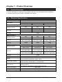
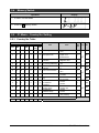
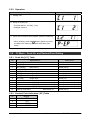
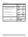
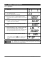
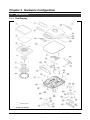
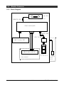
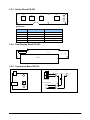
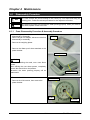
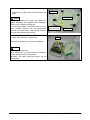
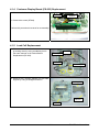
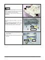
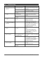
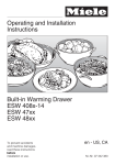
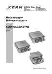
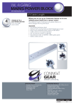
1
OUTLINE • Purpose of this manual This manual is edited for the authorized servicing personnel and used when carrying out services and maintenance of the machine. • Relative manual Refer to the operation manual for ususal operations. • Symbols used in this manual 1. Warning symbols Symbol Meaning Danger Indicates information that, if not avoided, is likely to result in loss of life or serious injury. Warning Indicates information that, if not avoided, may result in loss of life or serious injury. Caution Indicates information that, if not avoided, could result in relatively serious or minor injury, damage to the machine or faulty operation. 2. Explanatory symbols Symbol Note Indicates information to call or emphasize for attention to the note. Reference Indicates the reference page. Information Indicates information to help understanding. Reference Information Meaning • Readers of this manual This manual is edited for the servicing personnel. Use by other personnel is not permitted. • Note This manual may be revised in accordance with modification when made in the machine. All rights are reserved. Copying any part of this manual is prohibited without our permission. 1/32 IPC-WP Series Service Manual Contents Chapter 1. Product Overview .................................................................................... 3 1.1 Product Overview ......................................................................................................... 3 1.2 Standard Specifications ............................................................................................... 3 1.3 Appearance .................................................................................................................. 5 1.4 Operation Panel ........................................................................................................... 6 1.5 Outer Dimensions ........................................................................................................ 8 Chapter 2 Test Mode ................................................................................................. 9 2.1 Test Mode Flow............................................................................................................ 9 2.2 Starting Test Mode ..................................................................................................... 10 2.3 Ending Test Mode ...................................................................................................... 10 2.4 Memory Switch........................................................................................................... 11 2.5 C1 Mode – Country No. Setting ................................................................................. 11 2.5.1 Country No. Table ................................................................................................. 11 2.5.2 Operation .............................................................................................................. 12 2.6 C2 Mode – Scale No. and Decimal Point Setting ....................................................... 12 2.6.1 Scale No.[ X1 ] Table ............................................................................................ 12 2.6.2 Decimal Point Indication [ X2 ] Table .................................................................... 12 2.6.3 Operation .............................................................................................................. 13 2.7 C3 Mode – Span Adjustment ..................................................................................... 14 2.7.1 Operation .............................................................................................................. 14 2.8 F Mode – Setting Measuring Conditions and E2ROM Clear ...................................... 15 2.8.1 Operation .............................................................................................................. 15 2.8.2 Error No. List ........................................................................................................ 16 Chapter 3 Hardware Configuration ........................................................................ 17 3.1 Mechanisms ............................................................................................................... 17 3.1.1 Dual Display ......................................................................................................... 17 3.1.2 Single Display ....................................................................................................... 19 3.2 Electric Concerns ....................................................................................................... 21 3.2.1 Block Diagram ...................................................................................................... 21 3.2.2 Main Board PS-021 .............................................................................................. 22 3.2.3 Switch Board PS-022 ........................................................................................... 24 3.2.4 Dual Display Board PS-023 .................................................................................. 24 3.2.5 Connection Board PS-019 .................................................................................... 24 Chapter 4 Maintenance ........................................................................................... 25 4.1 Disassembly Procedure ............................................................................................. 25 4.1.1 Case Disassembly Procedure & Assembly Procedure ......................................... 25 4.1.2 Main Board (PS-021) Replacement ...................................................................... 27 4.1.3 Switch Board (PS-022) Replacement ................................................................... 27 4.1.4 Customer Display Board (PS-023) Replacement ................................................. 28 4.1.5 Load Cell Replacement ........................................................................................ 28 4.1.6 Airproof Rubber Ring Replacement ...................................................................... 31 4.2 Troubleshooting ......................................................................................................... 32 2/32 IPC-WP Series Service Manual Chapter 1. Product Overview 1.1 Product Overview • The IPC-WP Series is a water proof type digital scale which can be operated with two batteries. • The large LCD with 25mm height is provided for the display. 1.2 Standard Specifications Item Model name Description IPC-WP Series /IPC-WP DUAL Series IPC-WP 3 IPC-WP 6 IPC-WP 15 3kg 6kg 15kg Single range Single range Single range 0.001kg 0.002kg 0.005kg 3.000kg/0.001kg 6.000kg/0.002kg 15.000kg/0.005kg Non-OIML(ASIA) Weighing capacity Scale unit Accuracy 1/3000 OIML R76 Class lll 3kg 6kg 15kg Multi interval Multi interval Multi interval Scale unit 0kg to 1.5kg/0.001kg 1.5kg to 3kg/0.002kg 0kg to 3kg/0.002kg 3kg to 6kg/0.005kg 0kg to 7.5kg/0.005kg 7.5kg to 15kg/0.01kg Accuracy 1/1500 1/1200 1/1500 6lb/3kg 15lb/6kg 30lb/15kg Multi interval Multi interval Multi interval 0lb to 3lb/0.002lb 3lb to 6lb/0.005lb 0lb to 7.5lb/0.005lb 7.5lb to 15lb/0.01lb 0lb to 715lb/0.01lb 15lb to 30lb/0.02lb (0kg to 1.5kg/0.001kg) (1.5kg to 3kg/0.002kg) (0kg to 3kg/0.002kg) (3kg to 6kg/0.005kg) (0kg to 7.5kg/0.005kg) (7.5kg to 15kg/0.01kg) Weighing capacity lb/kg Switching Specification (USA) Weighing capacity Scale unit Accuracy Weigh platter size Display Environment condition Power source Current consumption Auto power off 1/1500 196mm(L)×226mm(W) Single display / Dual diaplay LCD type 6 digits (7segments) Height : 25mm Ambient temperature: -5ºC to +40ºC Relative humidity: 80%RH (Max.), no condensation Two D-sized dry batteries or AC adaptor [ Battery duration ] Two alkaline D-sized batteries (Approximately 500 hours) Max. 25mA Select: 60 minutes (default), 20 minutes or non Auto power off Weight (excl. battery) 3.2kg 3/32 IPC-WP Series Service Manual Item Option Description AC adaptor (Dealer Option) xOutput voltage y 3.2 to 6.0VDC (current load at 25mA, or at IPC connection) (caution) 1. Output voltage must not exceed 6.0V even if power supply voltage is at +10%. 2. Output voltage exceeds 3.2V even if power supply voltage is at -15%. y Generally, AC adaptor output voltage varies with load current. Confirm output voltage with a 25mA load current (IPC current) y Output plug configuration/polarity x Configuration Specification EIAJ RC-5320-2 - Polarity Center Plus 4/32 IPC-WP Series Service Manual 1.3 Appearance Front & Rear view Bottom view Sheet 3 Memory switch Battery cover assy Two D-sized dry batteries 5/32 Battery rubber plug (option) IPC-WP Series Service Manual 1.4 Operation Panel ASIA Specification Oceania Specification 6/32 IPC-WP Series Service Manual EU Specification USA Specification 7/32 IPC-WP Series Service Manual 1.5 Outer Dimensions (Unit: mm) 8/32 IPC-WP Series Service Manual Chapter 2 Test Mode The Test Mode is used for diagnosis and/or setting at maintenance service. 2.1 Test Mode Flow L003b START Program No. display C1 X Setup of country No. C2 XX Setup of scale No. and decimal point TARE TARE TARE TARE * Span adjustment C3 TARE Fxxx * TARE Setting measuring conditions TARE E2ROM clear ON/OFF ZERO + * END Note: Press the memory switch at any time during test mode to record the data to the E2PROM. Then “P-EP” appears in the display. 9/32 IPC-WP Series Service Manual ¡Key Functions (when setting value) Asia Key Oceania EU Function USA x Use at TEST mode startup. (Press this key while the TARE key is depressed.) x Use at TEST mode end x Use when selecting digits. x Press when fixing values after mode or data selection. x Increments values for each press during data change. x Press when entering C3 or F mode (Tactile switch in the main circuit board) Stores E2ROM data set for each item of the C and F mode. Memory Switch 2.2 Starting Test Mode Operation Display 1. Press and release the ON/OFF key while the TARE key is depressed. 2. Release the TARE key. 2.3 Ending Test Mode Operation Display 1. C mode / F mode status 2. Release the ON/OFF key after depressing for one second or more. 10/32 IPC-WP Series Service Manual 2.4 Memory Switch Operation Display 1. C mode / F mode status 2. Press the 2.5 Memory Switch. C1 Mode – Country No. Setting 2.5.1 Country No. Table 1 2 Country No. 3 4 5 USA 6 7 AUS CAN EU JPN ASIA 0 0 0 0 0 0 0 0 0 0 0 1 0 0 1 0 0 0 1 0 0 0 0 0 0 1 0 0 0 0 1 0 0 0 1 0 0 0 1 0 0 0 0 0 0 0 1 0 0 0 0 0 0 0 1 1 0 0 0 0 0 0 0 0 0 0 0 0 0 0 0 0 0 0 0 0 0 1 0 0 0 0 0 0 804 000 010 020 04E 080 090 Item WeiDigit ght Data 0: ±10% 1: ±2% 0: Lights on at true zero Zero point mark 1: Lights on at Provisional zero Below true zero 0: "___" indication 1: Negative value Cleaning tare weight 0: No by pressing ZERO key 1: Yes Decimal point 0: "." Indicator 1: "," 0: BLANK Over-scale indication 1: "OL" 0 : Not possible Tare subtraction 1: Possible Tare clear with ZERO 0: Possible key 1: Not Possible Stabilized, 0: 5 times. re-stabilized 1: 8 times. frequency Re-stabilization 0: 2 times over Starting range 1: 4 times over Stabilized/re0: 3 times stabilized range 1: 5 times 0: No Section adjustment 1: Yes (JAPAN) Start range 1 2 Bit D0 100 D1 4 D2 8 D3 1 D4 2 D5 101 4 D6 8 D7 1 D8 2 2 10 D9 4 D10 8 D11 ←Display of F mode Measurement Condition 11/32 IPC-WP Series Service Manual 2.5.2 Operation Operation Display 1. Stating Test 2. Setup of Country No. x To select the No., use the [ * ] key x Example: ASIA=2 3. When the C2 mode is then required, press the TARE key. x When finishing, press the Memory Switch to record the data to the memory, and enter the Ending Test Mode. 2.6 C2 Mode – Scale No. and Decimal Point Setting 2.6.1 Scale No.[ X1 ] Table X1 Specifications A/D Counts 1 3kg (2g/1g) Multi interval 30000 (20/10) 2 6kg (5g/2g) Multi interval 30000 (25/10) 3 15kg (10g/5g) Multi interval 30000 (20/10) 4 30kg (20g/10g) Multi interval 30000 (20/10) 5 3kg (1g) Single range 30000 (10) 6 6kg (2g) Single range 30000 (10) 7 15kg (5g) Single range 30000 (10) 8 30kg (10g) Single range 30000 (10) 9 6lb (0.005lb/0.002lb) / 3kg (2g/1g) Multi interval lb/kg 30000 (25/10) / 30000 (20/10) A 15lb (0.01lb/0.005lb) / 6kg (5g/2g) Multi interval lb/kg 30000 (20/10) / 30000 (25/10) B 30lb (0.02lb/0.01lb) / 15kg (10g/5g) Multi interval lb/kg 30000(20/10) / 30000 (20/10) C 60lb (0.05lb/0.02lb) / 30kg (20g/10g) Multi interval lb/kg 30000(25/10) / 30000 (20/10) D 100oz (0.1oz/0.05oz) Multi interval oz 20000 (20/10) 2.6.2 Decimal Point Indication [ X2 ] Table X2 1 2 3 4 Display "0" "0.0" "0.00" "0.000" 12/32 IPC-WP Series Service Manual 2.6.3 Operation Operation Display 1. Stating Test 2. Scale No. and Decimal point indication mode x Press the [ TARE ] key ON → (1st digit flashes) x Example: ASIA 3kg (1g) Single range X1=5, X2=4 X2 X1 2.1 Scale No. Setting x Press the [ * ] key ON four times (X1=5) X2 X1 2.2 Decimal point indication Setting x Press the [ ZERO ] key ON → (2nd digit flashes) X2 X1 x Press the [ * ] key ON three times (X2=4) X2 X1 x When the C3 mode is required, press the TARE key. x When finishing, press the Memory Switch to record the data to the memory, and enter the Ending Test Mode. 13/32 IPC-WP Series Service Manual 2.7 C3 Mode – Span Adjustment 2.7.1 Operation Operation 1. Stating Test 2. Span Adjustment mode Display 2.1 Press the TARE key ON for two times. 2.2 Press the [ * ] key ON → displays original A/D data (The normal range for original A/D data is 1000 to 25000 counts). 2.3 Press the [ * ] key ON with zero load on the weigh platter → Approx. 5000 count is diplayed. 2.4 Press the ZERO key if the count diverges from 5000 counts. 2.5 Put the weight same as weighing capacity on the weigh platter, then press the [ * ] key → "CAL" is displayed, then the A/D count becomes "35000" on the display. If the count diverges from 5000 counts, unload the weight and repeat the operations as set out in 2.4 and 2.5. 2.6 When the C3 mode is required, press the TARE key. x When finishing, press the Memory Switch to record the data to the memory, and enter the Ending Test Mode. Note • “CAL” operation can not be performed unless zero-point adjustment is finished. • “CAL” operation can not be performed unless the original A/D value exceeds 33300 counts when the weight is loaded. 14/32 IPC-WP Series Service Manual 2.8 F Mode – Setting Measuring Conditions and E2ROM Clear Note • All data has been fixed according to country specifications. • Altering data may not conform to weighing and measuring tests for a country. Reference • See 1.6 “C1 Mode-Country No. Setting” for Measurement Conditions Setup Table. Reference 2.8.1 Operation Operation 1. Stating Test 2. Setting measuring conditions Display 2.1 Press the TARE key for three times 2.2 Press the [ *] key → The least significant digit blinks. Whenever the [ *] key is pressed, the required digit can be selected. 2.3 Whenever the [ *] key is pressed, the figure of the digit which has blinked does the increment. 3. E2ROM clear ・ Any scene of F mode is possible. Press the ZERO key and [ * ] key. → "EP-C" then "C1-1" is displayed. 4. Note At this point, writing in E2ROM of change data in F mode and the default value to E2ROM clear has not been completed. Push the memory switch. Note E2ROM clear initializes Country No., Scale No., Zero, and Span adjustment values. It is necessary to set it again. ↓ Writing in E2ROM ・ Push the memory switch to memorize data. Note After E2ROM is cleared, if writing is performed in E2ROM without setting Country No., Scale No. nor Zero/Span adjustment value, and the power is turned on, "Err1" is displayed and it is not possible to use the machine. Set C1, C2, and C3 again. 15/32 IPC-WP Series Service Manual ¡Data after E2ROM is cleared Mode Data C1 1 JAPAN C2 11 Scale No.= 3kg (2g/1g) Multi interval C3 F Item Decimal point indication= " 0" Zero point and span adjustment value and each approximate value 804 Measurement condition 2.8.2 Error No. List Error No. Mode Item Err1 At power ON E2PROM unsetting or garbled data Err2 At power ON Outside start range Err3 Test mode Outside range where zero point can be adjusted (original A/D 1000 count or less) Err4 Test mode (Original A/D 25000 count or more) Err5 Test mode Outside span adjustment possible range (original A/D 33300 count or more) Err6 Normal mode Original A/D zero count or less 16/32 IPC-WP Series Service Manual Chapter 3 Hardware Configuration 3.1 Mechanisms 3.1.1 Dual Display 17/32 IPC-WP Series Service Manual IPC-WP Dual Display Service Parts List No. Parts Name Weighing Capacity Q'ty 1 PLATTER 1 2 SHEET PROTECT 1 3 PLATTER BRACKET 1 4 SUS RING INSIDE 1 5 AIRPROOF RUBBER RING 1 6 SUS RING OUTSIDE 1 7 SHEET 'DISPLAY' (---KG) Varied per country 2 8 SHEET 'DISPLAY' SWITCH Varied per country 1 9 PWB 'PS-022, KEY 1 10 AIRPROOF SPONGE BASE 1 11 PLATE SUPPORT 2 12 HARNESS ,C2, GND 1 13 LOAD CELL 14 PWB,PS-021A,MAIN 1 15 WIRE SADDLE 1 3kg/6kg/15kg 1 16 BASE 1 17 LEVEL UNIT 1 18 O-RING (RUBBER) 3.75*1.8 10 19 Varied per country 20 SLEEVE 2 21 SHEET_3 5 22 SPONGE BATTER COVER 1 23 BATTERY COVER ASSY 1 Varied per country 24 25 SHEET_2 1 26 FOOT LEVEL 4 27 Varied per country 28 Varied per country 29 SPRING 1 1 30 SPRING 2 1 31 HARNESS ,S2, DISPLAY 1 32 PWB , PS-023, DISPLAY 1 33 HARNESS ,C3, BATTERY 1 34 SHEET 2 35 HARNESS ,S2, AC-ADAPTER 1 36 FERRITE CORE (K5B RH14.2*15*6.36) 1 37 PWB 'PS-019' 1 38 SHEET_1 1 LEAD Varied per country 1 HOLDER Varied per country 1 41 NAMEPLATE Varied per country 1 42 CASE 1 43 BRACKET 1 39 40 44 45 BATTERY_RUBBER_PLUG 1 Option Note: Parts number may change without notice due to product improvement. 18/32 IPC-WP Series Service Manual 3.1.2 Single Display 19/32 IPC-WP Series Service Manual IPC-WP Single Display Service Parts List No. Parts Name 1 PLATTER 2 SHEET PROTECT 3 PLATTER BRACKET 4 SUS RING INSIDE Weighing Capacity 5 AIRPROOF RUBBER RING 6 SUS RING OUTSIDE 7 SHEET 'DISPLAY' (--- KG) Varied per country 8 SHEET 'DISPLAY' SWITCH Varied per country 9 PWB 'PS-022, KEY 10 AIRPROOF SPONGE BASE 11 PLATE SUPPORT 12 GND CORD 13 LOAD CELL 14 PWB,PS-021A,MAIN 15 WIRE SADDLE 16 BASE 17 LEVEL UNIT 18 O-RING (RUBBER) 3.75*1.8 1 1 1 1 1 1 1 1 1 1 2 1 1 1 1 1 1 10 1 2 5 1 1 3 1 4 2 2 1 1 1 2 1 1 1 1 1 1 1 1 1 1 1 3KG/6KG/15KG Varied per country 19 20 SLEEVE 21 SHEET_3 22 SPONGE BATTER COVER 23 BATTERY COVER ASSY Varied per country 24 25 SHEET_2 26 FOOT LEVEL Varied per country 27 Varied per country 28 29 Q'ty SPRING 1 30 SPRING 2 33 HARNESS,C3, BATTERY 34 SHEET 35 HARNESS ,S2, AC-ADAPTER 36 FERRITE CORE (K5B RH14.2*15*6.36) 37 PWB 'PS-019' 38 SHEET_1 39 LEAD Varied per country 40 HOLDER Varied per country 41 NAMEPLATE 42 CASE 43 BRACKET 44 BRCKPANEL 45 BATTERY_RUBBER_PLUG 3KG/6KG/15KG Option Note: Parts number may change without notice due to product improvement. 20/32 IPC-WP Series Service Manual 3.2 Electric Concerns 3.2.1 Block Diagram LOAD CELL (3 types depending on w eighing capacity) FERRITE CORE PWB,PS-021A,MAIN FERRITE CORE PWB 'PS-019' PWB 'PS-022, KEY PWB,PS-023,DISPLAY D-size dry batteries AC adapter Dealer Option DUAL DISPLAY 21/32 IPC-WP Series Service Manual 3.2.2 Main Board PS-021 ◆ Parts side CN1 CN4 CN5 JP3 JP2 CN2 CN6 JP5 JP6 SW 1 JP1 JP4 CN3 Note: There is no grounding wire in the maintenance parts. ◆ LCD side GND (B) (G) (W ) (R ) ) LCD Connector CN1: Key input Pin No. Function Remarks 1 GND 2 SW4 tare 3 SW3 * 4 SW2 zero 5 SW1 ON/OFF CN2: Power source input Pin No. Function 1 Power source 2 GND Remarks DC 2.4 to 6.0V CN3: Not used CN4: LCD display data output CN5: Not used 22/32 IPC-WP Series Service Manual CN6: Load cell input Pin No. Soldering land Function Remarks 1 (R) Vcc DC5V 2 (W) GND GND 3 (G) IN+ Approx 2.5V 4 (B) IN- Approx 2.5V 5 GND GND GND ¡Jumper JP1: Ferrite cut JP2: Ferrite cut JP3: Ferrite cut JP4: Ferrite cut JP5: Filter cut JP6: Filter cut ¡Switch SW5: E2ROM Memory switch 23/32 IPC-WP Series Service Manual 3.2.3 Switch Board PS-022 SW1 SW2 SW4 SW3 G Y O R BR y Harness Pin No. Function Remarks BR GND SW4 SW3 SW2 SW1 tare * zero ON/OFF R O Y G 3.2.4 Dual Display Board PS-023 CN1 LC D 1 P S -023 LCD 3.2.5 Connection Board PS-019 NC2 P S-019 + CN2 2 - 1 CN3 1 +V 2 GND Dry batteries NC3 CN1 AC adapter plug jack NC1 2 4 3 24/32 IPC-WP Series Service Manual Chapter 4 Maintenance 4.1 Disassembly Procedure 4.1.1 Note The seal restricts the peel according to the country by a no report and doing as wanting put it. Follow the relevant procedure for the respective countries. Caution The water proof sheet is to maintain the water proofing property. When you remove the sheet, replace it with a new one. Case Disassembly Procedure & Assembly Procedure 1. When using dry batteries, remove them before disassembly or assembly. When using an AC adaptor, disconnect it before disassembly or assembly. Platter 2. Remove the weighing platter. 3. Remove the Water proof sheet attached to the platter bracket. Sheet protect Caution When re-assembling the scale, use a new Sheet protect. When affixing the new sheet protect, completely remove the starch left on the bracket. Otherwise, the water proofing property will be deteriorated. 4. Remove the 12 M4 nuts. Platter bracket Platter bracket 5. Remove the 4 M4 screws, then remove the platter bracket. M4 Nut M4 Screw 25/32 IPC-WP Series Service Manual 6. Remove the Approval seal. 7. Remove the 10 M4 screws located around the base. Base M4 Screw Caution When re-assembling the scale, first fasten the screws tentatively, then tighten them completely one by one in a diagonal sequence. If you strongly tighten a particular point first, the water proofing property will be deteriorated because you cannot push in the packing between the upper case and the base evenly. 8. Pull out the connector from CN1 on the main board, then remove the upper case. Sheet (Approval seal) O-ring CN1 Perform this procedure in reverse for assembly. Caution Affix a new Sheet protect. When affixing the new sheet protect, completely remove the starch left on the bracket. Otherwise, the water proofing property will be deteriorated.。 26/32 IPC-WP Series Service Manual 4.1.2 Main Board (PS-021) Replacement 1. Detach the cell cord wires by using a soldering iron. 2. Remove the screw (ST8x8). Cell cord ST8×8 3. Disconnect the power harness from the connector. Grounding cord 4. Disconnect the power display harness from the connector. Power harness 5. Remove the grounding wire by using a soldering iron. 6. Perform the procedure in reverse when assembling a new main board. 7. After re-assembling all the parts (from the case to the weighing platter), clear E2ROM and perform settings and span adjustment in C1, C2, and C3 modes. Customer display harness 4.1.3 Switch Board (PS-022) Replacement 1. Remove the 6 screws (ST8x8). Perform this procedure in reverse for re-assembly. 27/32 ST8×8 IPC-WP Series Service Manual 4.1.4 Customer Display Board (PS-023) Replacement 1. Disconnect the harness from the connector. Harness ST8×8 2. Remove the screw (ST8x8). Perform this procedure in reverse for re-assembly. 4.1.5 Load Cell Replacement 1. Disconnect the cell cord wires and the grounding wires by using a soldering iron in the same manner as for Switch Board Replacement (PS-022). Plate support M6×25 Cell cord Grounding cord 2. Remove the 2 screws (M6x25) on the Plate support by using a hexagonal wrench. Plate support M6×25 Base 28/32 IPC-WP Series Service Manual 3. Remove the 4 Sheet 3s. Sheet 3 Caution When re-assembling the scale, use a new sheet protect. When affixing the new sheet protect, completely remove the starch left on the bracket. Otherwise, the water proofing property will be deteriorated. 4. Remove the 4 Screws (M5x5) The picture shows the position of the screws (M5x5). The two screws on the right side include a collar, flat washer, and spring washer. The other two screws on the left side include a flat washer and spring washer, but no collar. Collar M5×15.SW.W 5. Cut the lock tie that is holding the cell cord wires and grounding wires to the bottom of the Platter bracket. 6. Pull out the Ferrite core that is inserted into the cell cord. Ferrite core 29/32 Lock tie IPC-WP Series Service Manual 7. Remove the 2 Screws (M6x25) that are holding the Load cell. Load cell Load Cell 3kg: CZL-6d-C3-5kg-1000 6kg: CZL-6d-C3-10kg-1000 M6×25.SW.W Plate support 15kg: CZL-6d-C3-25kg-1000 Assembly procedure 1. Adjust the clearance limit by tightening the screw, spring washer, and flat washer on the plate support. 2. When you finish adjusting the clearance, paste the screw lock coagulant. The clearance limit is shown below. 3. For assembly, perform the disassembly procedure in reverse. 4. After re-assembling all the parts, clear E2ROM and perform settings and span adjustment in C1, C2, and C3 modes. 30/32 IPC-WP Series Service Manual 4.1.6 Airproof Rubber Ring Replacement Caution Airproof rubber ring M4×10 If the Airproof rubber ring is damaged, make sure that there is no water-ingression in the scale. 1. Remove the 8 Screws (M4x10) on the SUS ring inside. 2. Remove the Diaphragm and SUS ring outside. 3. Perform the procedure in reverse for assembly. Airproof rubber ring Caution When re-assembling the scale, fasten screws tentatively, then tighten them completely one by one in a diagonal sequence. If you strongly tighten a particular point first, the water proofing property will be deteriorated because you cannot push in the packing between the upper case and the base evenly. 31/32 SUS ring inside SUS ring outside IPC-WP Series Service Manual 4.2 Troubleshooting Symptom Cause 1. The display check does not 1. Trouble of dry battery power supply system start when the power switch is pushed. 2. AC adaptor trouble 3. Main board PS-021 trouble 2. Power ON → Display check 1. Garbled E2ROM data or → "Err1" initialized state. 2. Main board PS-021 trouble 3. Power ON → Display check 1. Outside weight value start → "Err2" range 4. Power ON → Display check 1. Weight value is unstable. → “0”kg does not appear on the display. 5. Weight varies at four corners. 1. External or load cell trouble 6. The ZERO or TARE key does not function. 1. Outside of zero-adjustment or tare subtraction range 2. Weight value is unstable. 7. The power supply cuts when time passes. 1. Auto power OFF setting. 2. Main board PS-0 21 trouble 32/32 Measure • Check and replace dry batteries • Confirmation and exchange of battery harness • Check output voltage (DC2.4-6.0V) and replace AC adaptor • Replace the main borad PS-021. • Initialize, perform C1, and C2 and C3 settings, then push the memory switch. • Replace the main board PS-021. • Check if anything is placed on the platter. If so, remove it. • Replace the load cell. • Replace the main board PS-021. • Check if something comes in contact with the platter. If so, remove it. • Check if there is wind or vibration near the machine. If so, avoid these. • Replace the main board PS-021. • Replace the load cell. • Check if the horizontal state is being kept. • Check if there is foreign article between the platter and the case. • Check if space of limit adjustment screw is narrow • Replace the load cell. • Check that zero-adjustment or tare subtraction is within the specified range. • Check if something comes in contact with the platter. If so, remove it. • Check if there is wind or vibration near the machine. If so, avoid these. • Replace the main board PS-021. • Replace the load cell. • Check if the auto power OFF function works. • Default is 60 minutes. • Replace the main board PS-021. IPC-WP Series Service Manual PN 86367 01/2012