1
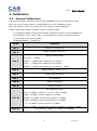
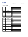
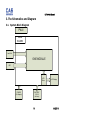
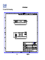
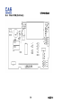
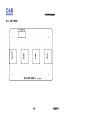
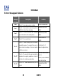
PW-II Service Manual PW-II SERVICE MANUAL 1 9/2/2011 PW-II Service Manual < Table of Contents > 1. Introduction ............................................................................................................................... 3 1.1. Preface .................................................................................................................................... 3 1.2. Precaution ............................................................................................................................. 3 1.3. Specifications ...................................................................................................................... 4 1.4. Key ............................................................................................................................................. 5 1.5. Sealing Method ................................................................................................................... 6 2. Calibration ................................................................................................................................... 8 2.1. General Calibration .......................................................................................................... 8 2.1.1. C4 Setting ............................................................................................................. 9 2.1.1.1. C4-1 Setting................................................................... 9 2.1.1.2. 3. 4. C4-3 Setting................................................................... 9 2.1.2. SPAN Calibration Setting (C-3) .............................................................. 10 2.1.3. Gravity Constant Value Setting (C-9) ................................................ 10 2.1.4. Calibration factor Setting (C-10) .......................................................... 10 2.1.5. Displaying Real A/D Value (C-5) .......................................................... 11 2.1.6. Percent Calibration (C-7) .......................................................................... 12 2.1.7. Battery Calibration (C-8) ........................................................................... 12 The Schematics and Diagram ......................................................................................... 13 3.1. System Block Diagram ................................................................................................. 13 Exploded View ................................................................................................................................ 14 5. Load Cell drawing.................................................................................................................. 15 6. Part Location ............................................................................................................................ 16 6.1. Main PCB (Top) ................................................................................................................ 16 6.2. Main PCB (Bottom) ........................................................................................................ 17 6.3. KEY PCB ................................................................................................................................ 18 6.4. BATTERY PCB (Bottom) ............................................................................................... 19 7. Error Messages & Solution............................................................................................... 20 2 9/2/2011 PW-II Service Manual 1. Introduction 1.1. Preface Thank you for purchasing of our CAS scale. This scale has been designed with CAS reliability, under rigid quality control and with outstanding performance. WE hope that your departments enjoy with high quality of CAS product. This manual will help you with proper operations and care of the EB series. Please keep it handy for the future references. 1.2. Precaution Make sure that you plug your scale into the proper power outlet. Place the scale on a flat and stable surface. Plug into a power outlet 30 minutes before operations. Keep the scale away from strong EMI noises may cause incorrect weight readings. This scale must be installed in a dry and liquid free environment. Do not subject the scale to sudden temperature changes. Do not subject the platter to sudden shocks. If the scale is not properly level, please adjust the 4 legs at the bottom of the scale (turn legs clockwise or counterclockwise) so as to center the bubble of the leveling gauge inside the indicated circle. 3 9/2/2011 Service Manual PW-II 1.3. Specifications MODEL CAPACITY/e DISPLAY MAX TARE TEMPERATURE RANGE POWER SUPPLY POWER CONSUMPTION BATTERY OPERATING TIME PLATTER SIZE DIMENSIONS PRODUCT WEIGHT OPERATING POWER PW- (2kg) PW- (5kg) Dual Interval Dual Interval 1kg/0x0005kg 2.5kg/0x001kg 2kg/0.001kg 5kg/0.002kg Dual Interval Dual Interval 2.5lb/0x001lb 4lb/0x002lb 5lb/0.002lb 10lb/0.005lb Dual Interval Dual Interval 40oz/0.02oz 80oz/0.05oz 80oz/0.05oz 160oz/0.1oz 91 x 39 [mm] / 3.6 x 1.5 [inch] 5 digits LCD - 0.9995 kg - 2.499 kg PW- (10kg) Dual Interval 4kg/0x002kg 10kg/0.005kg Dual Interval 10lb/0x005lb 20lb/0.01lb Dual Interval 200oz/0.1oz 400oz/0.2oz - 3.998 kg -10°C ~ +40°C / 14 ℉ ~ 104 ℉ 1.5V x 6 (AA size Battery) APPROX. 0.25W 150 hours (Manganese battery) 400 hours (Alkaline battery) 222(W) x 151(D) [mm] / 8.7(W) x 5.9(D) [inch] 239(W) x 227(D) x 66(H) [mm] / 9.4(W) x 8.9(D) x 2.6(H) [inch] 1.5kg / 3.3lb 9V Adaptor 300mA 4 9/2/2011 PW-II Service Manual 1.4. Key Key Function HOLD To make the weight of item stable. This weight is average value. UNIT Used to convert the unit of weight TARE To input or cancel the tare (the weight of container). ZERO (-O-) [Set] POWER To set zero point To do [SET] key in the SETUP mode. To turn on or off. 5 9/2/2011 PW-II Service Manual 1.5. Sealing Method 6 9/2/2011 PW-II 7 Service Manual 9/2/2011 PW-II Service Manual 2. Calibration 2.1. General Calibration Pressing and holding calibration switch press [POWER] key to go to calibration mode. User can move to other mode by using [ZERO] key in the calibration mode. User also moves to other sub-modes for each mode by using [TARE] key. Please simply follow below procedure to move to other mode. (1) Calibration Mode: Pressing and holding “Calibration Switch” press [POWER] key. (2) It displays “CAL-0” after “CAL”, and it blinks the version of scale three times. (3) Selecting menu: press [TARE]. (4) ENTER(Setting) : [TARE] key MODE Function CAL 1 Display normalized AD CAL 2 Display Keypad infomationWeight Setting Mode “UnLoad” → [TARE] → CAL 3 “MIDD” → [TARE] after loading for 1/3 weight → “FULL” → [TARE] after loading for Full weight → “MIDD” → [TARE] after loading for 1/3 weight → “END” CAL 4 Option Setting ( Table 1 참조 ) CAL 5 Display filtered Raw AD CAL 7 % Calibration CAL 8 Battery calibration CAL 9 Gravity constant Set calibration factor “Unit” [TARE] select 0, 1 (0:kg, 1: lb) [TARE] “CAPA” [TARE] select capacity [TARE] CAL 10 “MCAPA” [TARE] select mid-capacity [TARE] “W-dP” [TARE] Select Decimal Point [TARE] “ 1 d ” [TARE] Select division [TARE] “Dual” [TARE] Enable dual interval (0:disable, 1:enable) TARE CAL 11 Set nation(00 : OIML , 01 : NTEP , 02: KOREA) 8 9/2/2011 PW-II Service Manual < Modes > 2.1.1. C4 Setting 2.1.1.1. BIT 6~7 BIT5 C4-1 Setting Initial Zero range Tare Type 3 5% 2 10% 1 3% 0 2% 0 Proper tare 1 Full Tare 3 (+), (-) Direction successive Tare 2 (-) Direction successive Tare 1 (+) Direction successive Tare 0 One Time tare 0 "." dot 1 "," comma 0 Don't use 1 Use 0 Don't use 1 Use 0 Don't use 1 Use 0 Don't clear 1 Clear 0 Don't clear 1 Clear 0 Don't use 1 Use 0 No 1 Yes BIT4 BIT 2~3 Successive tare BIT1 BIT0 2.1.1.2. C4-3 Setting BIT7 Dot Type BIT6 Use Preset tare BIT5 Use Back light BIT4 Use Head message BIT3 Use gram BIT2 Use oz BIT1 Use lb BIT0 Use Kg 9 9/2/2011 PW-II Service Manual 2.1.2. SPAN Calibration Setting (C-3) (1) Pressing and holding “Calibration Switch” press [POWER] key. After “CAL” message blinks three times and shows the version of scale, it displays “CAL 1” message. (2) Press [ZERO] to display “CAL-3”. (3) Press [TARE] key and then it displays “zero ” message. (4) Press [TARE] key and then it displays “midup” message (5) Load middle weight (ex:1/3 full capacity) on the platform (6) Press [TARE] key and then it displays “span ” message (7) Load full weight on the platform (8) Press [TARE] key and then it displays “middn” message (9) Load middle weight (ex:1/3 full capacity) on the platform (10) Press [TARE] key and then it display “CAL 3” message 2.1.3. Gravity Constant Value Setting (C-9) Current gravitational Acceleration value is set to 9.7994 m/s2 . (11) Pressing and holding “Calibration Switch” press [POWER] key. After “CAL” message blinks three times and shows the version of scale, it displays “CAL-1” message. (12) Press [ZERO] to display “C-9”. (13) Press [TARE] key, and then “ G-1“ message and “9.7994” will be shown. The first digit,”9” will blink. (14) Input a gravitational acceleration value by using [ZERO] key. (15) Press [TARE] key, and then “G-2“ message blinks.“9.7994” will be shown. The first digit,”9” will blink. (16) Input a gravitational acceleration value by using [ZERO] key. (17) Press [TARE] key to save the gravitational acceleration value, and “C-9 ” message will be shown. 2.1.4. Calibration factor Setting (C-10) (1) Pressing and holding “Calibration Switch” press [POWER] key. (2) After “CAL” message blinks three times and shows the version of scale, it displays “CAL-1” message. (3) Press [ZERO] to display “C-10”. (4) Press [TARE] key, and then “UNIT “ message and “0” will be shown. The first digit,”0” will blink. It means calibration unit is “kg” (0 : kg, 1 : lb) (5) Input a calibration unit by using [ZERO] key. (6) Press [TARE] key, and then “CAPA“ message blinks.“0015” will be shown. The first 10 9/2/2011 PW-II Service Manual digit,”0” will blink. It means a full-capability is “15 (calibration unit, kg or lb)” (7) Input a capability by using [ZERO] key. (8) Press [TARE] key, and then “MCAPA“ message blinks.“0005” will be shown. The first digit,”0” will blink. It means a mid-capability is “05 (calibration unit, kg or lb)” (9) Input a capability by using [ZERO] key. (10)Press [TARE] key, and then “W-dP “ message blinks.“3” will be shown. The first digit,”3” will blink. It means a weight decimal point is “3 (will display 0.000)” (11)Input a weight decimal point by using [ZERO] key. (12) Press [TARE] key, and then “1d “ message blinks.“0.005” will be shown. The third digit,”0” will blink. It means a division is “0.005 (calibration unit, kg or lb)” (13) Input a division by using [ZERO] key. (14) Press [TARE] key, and then “dual “ message blinks.“1” will be shown. The third digit,”1” will blink. It means a dual interval is disable. (0 : disable, 1 : enable)” (15) Input a dual interval enable by using [ZERO] key. (16) Press [TARE] key to save the calibration factor, and “C-10 ” message will be shown. 2.1.5. Displaying Real A/D Value (C-5) Display Raw AD 11 9/2/2011 PW-II Service Manual 2.1.6. Percent Calibration (C-7) (1) Pressing and holding “Calibration Switch” press [POWER] key. After “CAL” message blinks three times and shows the version of scale, it displays “CAL 1” message. (2) Press [ZERO] to display “CAL-7”. (3) Press [TARE] key and then it displays “per 0 ” message. Select the percent value using the [numeric] key. You can choose 10~90 percent. (4) Press [TARE] key and then it displays “zero” message (5) Press [TARE] key and then it displays “pspan ” message (6) Load choice percentage weight of full weight on the platform (7) Press [TARE] key and then it displays “CAL 7” message 2.1.7. Battery Calibration (C-8) (1) Pressing and holding “Calibration Switch” press [POWER] key. After “CAL” message blinks three times and shows the version of scale, it displays “CAL 1” message. (2) Press [ZERO] to display “CAL-8”. (3) Press [TARE] key and then it displays voltage of battery. (4) Change the jumper-pin of main PCB, „BAT‟ to „+5V‟. (5) Press [ZERO] key two times and then Press [-] key two times. And then it display „500‟ (6) Change the jumper-pin of main PCB, „+5V‟ to „BAT‟. (7) You can see the calibrated voltage of battery. 12 9/2/2011 EB Service Manual 3. The Schematics and Diagram 3.1. System Block Diagram PW-II MAIN BOARD Load Cell ONE MODULE KEY LCD Driver LCD Display Dry BATTERY 1.5V X 6 (AA size) POWER (9V Adaptor) 13 9/2/2011 EB Service Manual 4. Exploded View 14 9/2/2011 EB Service Manual 15 5. Load Cell drawing 25 112 112 SW (spring element) 2090501 15 9/2/2011 00 EB Service Manual 6. Part Location 6.1. Main PCB (Top) 16 9/2/2011 EB Service Manual 6.2. Main PCB (Bottom) 17 9/2/2011 EB Service Manual 6.3. KEY PCB 18 9/2/2011 EB Service Manual 6.4. BATTERY PCB (Bottom) 19 9/2/2011 EB Service Manual 7. Error Messages & Solution Error Message Description Solution on Display "Err 0" "Err 1" "Err 2" "Err 3" The "Err 0" occurs when scale is not stable. Remove unstable facts. The "Err 1" occurs when a current zero point has Please call your CAS shifted from the last span calibration. dealer. The "Err 2" is not a real error. Only it prompts Please call your CAS return CAL switch to the normal position. dealer. Please remove the The "Err 3" is an overload error. weight. The "Err 11" means a writing error of the internal “Err 11” nonvolatile memory. To recognize this error, be If it still has "Err 11", sure to check the voltage on the circuit and do replace the digital module. calibration procedures. The "Err 12" warns that the scale has lost the “Err 12” parameters for weighing regulations or has lost the factors for a digital span calculation. “Err 14” Enter each condition codes again (?). Please try a span calibration again if still not fixed. The "Err 14" means calibration range is not Please call your CAS correct. dealer. 20 9/2/2011