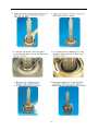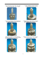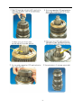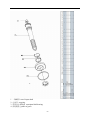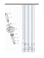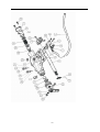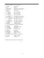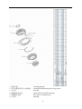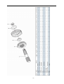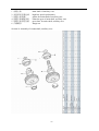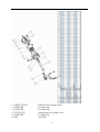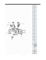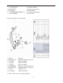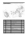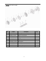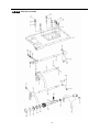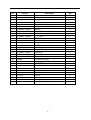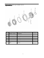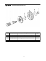
1
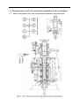
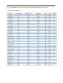
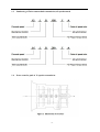
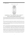
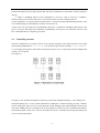
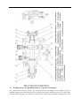
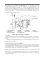
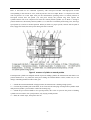
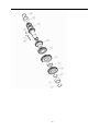
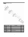
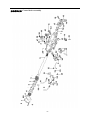
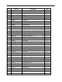
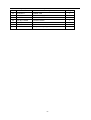
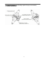
Twin countershaft transmission, all synchronized
Catalogue
1
Main parameters of Twin countershaft transmission, all synchronized
1.1 Main section picture of the twin countershaft transmission, all synchronized ·······1
1.2 Main parameters of Twin countershaft transmission, all synchronized············2
1.3 Numbering of Twin countershaft transmission, all synchronized ·················4
1.4 Power transfer illustration of 12 speeds transmissions··························5
2
The structure of Twin countershaft transmission, all synchronized
2.1 Shifting structure illustration··············································6
2.2 Controlling structure illustration ··········································8
2.3 Working theory of 12 speeds transmission’ air path····························9
2.4 Working theory of static power-taking off·································10
3
Maintenance awareness for using Twin countershaft transmission, all synchronized
3.1 Use and maintenance·············································11
3.2 Pay attention ·······················································12
4
assemble and disassemble the Twin countershaft transmission, all synchronized
4.1 Assemble and disassemble the shifting structure (single H valve) ··············14
4.2 Assemble and disassemble the shift bar····································17
4.3 Assemble and disassemble the auxiliary case································19
4.4 Assemble and disassemble the main case··································26
5
Typical structure and working theory of 16 speeds transmission
5.1 Typical structure of the 16 speed transmission··························38
5.2 Working theory of 16 speeds transmission’ air path ·························39
5.3 Main points for assembling and disassembling the 16 speed transmission··········42
6
Catalogue of service parts
6.1 Clutch housing and housing of transmission·······························50
6.2 Main shaft assembly···················································52
6.3 Countershaft assembly·················································54
6.4 Input shaft assembly··················································56
5, Reverse countershaft assembly···········································57
6, Controlling device assembly·············································58
7, Shift Bar assembly·····················································60
8, Drive gear assembly of auxiliary case·······································62
9, Main shaft assembly of auxiliary case······································63
10, Countershaft assembly of auxiliary case····································64
11, Shifting cylinder assembly of auxiliary case·································65
12, Rear cover assembly·················································66
13, Air filtration adjuster assembly\·········································68
14, Single H assembly················································69
15, Spare parts of 16 speeds transmissions·································70
1、Main parameters of Twin countershaft transmission, all synchronized
1.1
Main section picture of the twin countershaft transmission, all synchronized
-1-
1.2
Main parameters of Twin countershaft transmission, all synchronized
Performance parameter
-2-
-3-
1.3
Numbering of Twin countershaft transmission, all synchronized
1.4
Power transfer path of 12 speeds transmission
-4-
2
Typical structure of twin-countershaft transmission, all synchronized
The Main and Aux Case are all adopt two countershafts with same structure, alternate with180º, the power
is input from input shaft, and then it can be distributed to the two countershafts, finally influx to the Main
shaft for output, so is the Aux Case.
As theoretically each countershaft can only transfer 1/2 torque, so using the twin-countershaft can reduce
the center distance of transmission, the width of gears is less, axial size is shorter and weight is lighter.
After using two countershafts, each speed gears on Main shaft must be mesh with two gears on
counter-shafts at the same time.
For meeting the correct meshing and distributing the load evenly, the gears of main shaft are in floating
status on Main Shaft. The Main shaft adopts the floating structure with hinge joint. The front-neck of Main
Shaft insert into the hole of Input Shaft, the guide sleeve with oil is pressed into hole, there is enough radial
clearance between the neck of Main Shaft and Guide Sleeve. The back end of Main Shaft insert into inner
hole of Drive Gear in Aux Case by involute spline, the shaft neck of Drive Gear in Aux. Case is supported
on hole of the ball bearing.
Owing to each speed Gears of Main Shaft are in floating state on Main Shaft, thus traditional roller-bearing
is canceled, which make the mainshaft’s structure simple. When it works, force by two Countershaft Gears
against to Main Shaft Gears are equal in intensity and opposite in direction, therefore they will counteract
each other, at this moment the main shaft is only bearing the torque, but not bearing flexural torque, so the
stress condition on main shaft and bearing is improved, and the reliability and durability of Transmission
are improved greatly.
-5-
2.1
Shifting structure
The synchronizer in transmission make shifting easier and more convenient, low collision and noise, so the
gears’ life is prolonged, performance can be enhanced, so except the reverse speed gear, other gears are
equipped with synchronizers. Inertia synchronizer ensures that it can shift to gears stably and smoothly. It
consists of two kinds, inertia locking-stop style and inertia force style. The most prevailing is locking-stop
style.
The lock-ring synchronizer has compact structure、good performance、high reliability and low cost, so it is
widely used currently. The only shortage is that its friction torque is a little lower. The twin cone lock-ring
synchronizer is a newly designed synchronizer device, based on similar working theory and structure of the
lock-ring synchronizer. It inherits the advantages of the lock-ring synchronizer, and makes up the shortage
by improving the friction torque.
Figure 4 is 5-6 speed synchronizer, 5th speed and 6th speed are all cone faces. 5th speed and 6th speed
share the synchronizer gear spacer hub、sliding block and spring. Both of 5th and 6th have three cone parts
(5、6、8), and six single splines on outside cone (5) of synchronizer combines six spline grooves on the
inside cone (8) of the synchronizer, so both the outside cone (5) and inside cone (8) rotate with the main
shaft. But six protrudings of cone (6) combine 6 holes of the conjoint ring (7), so the cone (6) rotate with
5th speed gear. As a result, when the transmission is shifting from 4th speed to 5th speed or shifting from
6th speed to 5th speed, a relative speed difference will be produced between the 5th speed gear and the
mainshaft, at this time two sliding friction cones of the 5th speed synchronizer cone mechanism will start
work. There under the same condition, the friction torque made by the axial thrust of the synchronizer gear
spacer equals to sum of the friction torque of the two cones, that is friction torque made while shifting the
5th speed is approximately 2 times that of the single cone, so reducing the shifting force for about 50%.
-6-
Working process:
When shifting, meshing bush is taking sliding block and pushing outer cone move forward, because there
is aperture after installing synchronizer, cone pushes gear ring and make it close to gear. The friction
moment produced by speed difference make out cone rotate a certain angle and fixed by sliding block. At
this time, the gear sleeve moves, interface of gear sleeve contacts with that of out cone’s outer spline. The
shifting force further pushes outer cone through lock-stop slant face, friction happens, consequently the
synchronizing forward shifting can be stopped. When the friction moment counteracts with inertia moment
of the part being combined, speed difference and friction moment disappear. Ring moment force the outer
cone back to position, the lock-stop slant face disengaged, meshing sleeve meshes with synchronizing gear,
ensuring a smooth shifting.
Shifting process:
The vehicle driving, each part of transmission position as figure 3 after the driver remove speeds. At this
moment, the power from Motor and Clutch transferred to the Input Shaft, through involute spline transfer
to Input Shaft Gear, the Input Shaft Gear and Countershaft Drive Gear are meshed each other. The power
transferred to the Countershaft, owing to each speed gears on Countershaft and countershaft connecting
together, so rotate together. Each speed gears on Countershaft makes each speed gears on Main Shaft rotate
together. Because Sliding Clutch of each synchronizer in neutral position, so each speed gears on Main
Shaft racing, the Main Shaft no power output.
When the driver operate shifting lever for hangs 5th Speed in cab. Through drive Mechanism of shifting
lever, the Yoke Bar (5th & 6th speed) makes Yoke (5th & 6th speed ) move to right, the foot of Yoke push
Sliding Clutch move to axial direction, now two sliding friction cones of the 5th speed synchronizer cone
mechanism will start work. When the relative angular velocity of 5th gear and main shaft is zero, inner
spline of synchronizer will mesh the outer spline of 5th gear slightly. So far, entirely hang speed have
completed. After the power from Motor and Clutch transferred to Input Shaft , through the spline
transferred to Input Shaft Gear, and transferred to symmetrical two Countershaft Drive Gears , and through
symmetrical two Countershaft Gears (5th Speed) transferred to synchronizer sliding、Main Shaft through
Spline meshed, and then the power through Drive Gear of Aux Case input Aux Case, Finally the output
flange of Transmission output the power through Aux Case.
u
Analysis of inertia synchronizer’s defects
Lock-ring synchronizer: single cone-face synchronizer, multi-face synchronizer
1) inactive at a early stage: Under usual condition, within warranty period, allowance of synchronizer
disappear, make lock and synchronizing effect of synchronizer inactive, it maybe caused by the
following factors:
① The disengagement of synchronizer is not thorough enough, so when shifting the synchronizer
need to bear more torque, there is a constant friction on the synchronizing cone face, making it inactive.
② The gear ring’s cone face of synchronizer does not have a good lubrication, when there is not
enough lubrication on the cone face, threads on it will soon wear out, and cause high temperature, making
it inactive.
③ Lubrication oil within the transmission is not pure enough, the oil is too dirty, the impurity
-7-
material will impair the gear ring’s threads, that will affect synchronizer’s performance and life, making it
inactive.
④ There is machining defects on the synchronizer’s cone face, such as cone face’s roundness,
linearity, and run out, all of this will cause severe friction on the cone face, making it inactive.
2) The synchronizer’s teeth get broken and fractured, it is caused by design and machining problem, such
as too small filleting, too thin thickness of shell, cracks and so on.
3) Inner cone face gets broken. We should think if the space is suitable for installing synchronizer, if the
space is too big it will impair the performance and durability, if the space is too small, the cone face will
have a bad lubrication or completely get broken.
2.2
Controlling structure
The basic mechanism of 12 speeds series is twin H remote operation, with impact structure, clear speed
position and good handle. R1、2、3、4、5、6 are at the low-speed section, and R2、7、8、9、10、11、
12 are at high-speed position. The neutral of low-speed section is at 3, 4 speeds, the neutral of high-speed
section is at 9,10 speeds.
(See figure 5)
See figure 6, the operation mechanism is made up of operation mechanism housing、outer shifting arm、
horizontal shifting level、reverse switch control block、shifting bar、compressed spring, air plug、indicator
switch、starting pin、and so on. It is use for choosing a speed、hanging a speed and disengage a speed. Each
side of the shifting bar has a fan-shaped convexity, and grooves on the convexity control neutral indicator
switch and air-path control valve. The reverse indicator switch is controlled by moving and rotating the
reverse switch control block.
-8-
2.3
Working theory and pneumatic path of 12 speeds transmission
The compressed air from the vehicle, will be decreased from 0.7-0.8Mpa to 0.57-0.6Mpa by the air
filtrating regulator, then enter main pipe and air entering control pipe. When the main case is at the neutral
position, air-path stopping valve opens, the compressed air enters into the air-path commuting valve. The
-9-
compressed air enters into cylinder vent plug through low-speed pipe, the cylinder’s piston moves
synchronizing bush of auxiliary case to mesh with reduction gear, at this time, transmission is at all
low-speed, as R1,1,2,3,4,5,6 speeds; select High at the preselector, there is no air in the outgoing pipe, the
compressed air comes into high-speed pipe and then to cylinder’s high-speed incoming vent plug, the
cylinder’s piston moves synchronizing bush of auxiliary case to mesh with drive gear of auxiliary case, at
this time, the transmission is at all high-speed, as R2,7,8,9,10,11,12. Neutral position of low speed is 3,4
speed. Neutral position of highed is 9,10 speed.
Pay attention:
1) The air control valve only opens when it’s in neutral position, when shifting, the air path will be
blockaded at the valve. That is, only when transmission is in neutral position, can shifting speeds be
realized.
2) When low speed, there is air at outgoing vent of the pre selector; when high speed, there is no air at
outgoing vent of the pre selector.
2.4
Working theory of static Power taking off
In order to meet certain demands of special vehicles, at rear and down part of 12JS180T transmission,
between clutch housing and transmission, PTO can be installed. Power taking-off from the lengthened
Countershaft of the Aux case, it is called rear PTO. It’s most prevailing nowadays. If it’s installed between
clutch housing and transmission it’s called front PTO or all-power PTO.
When the rear PTO applied, the Aux Case must be engaged in the neutral position for the purpose of power
taking-off and stop. To deal with this problem, it is simple to remove the cover of Aux Case cylinder and
add a neutral position cylinder. Structure of neutral position cylinder is shown in figure 8, and the indicated
location is neutral position.
- 10 -
Hole A and Hole B are connected separately with low-speed air-inlet and high-speed air-inlet
corresponding to the twin H air valve, with air-pressure of 0.57-0.6 Mpa. Hole C is compressed air inlet
with air-pressure of 0.7-0.8 Mpa. First put the Transmission operating rocker at neutral position of
low-speed section, here the piston (15) will press closely the position ring, then operate the
cylinder-control vale to let compressed air enter the neutral position cylinder (9) via Hole C. Owing to
pressure difference, the neutral position cylinder (11,13) will move left till the position ring, here, the range
speed piston (15) will be in neutral position. When you shift to a proper speeds, connect with air path of
PTO, engage the clutch, the static power taking off can be realized.
If mid-position cylinder was adopted instead of pressure-adding cylinder, the transmission and vehicle’s air
pressure difference is very small, the static power taking off would be hard to realize, in that case, we can
change controlling method to achieve that goal.
1) Switch the transmission handle to high position, the transmission is shifting to high speeds.
2) Connect the pneumatic path of the PTO, let air come into the inlet plug of mid-position cylinder. Push
mid-position cylinder’s piston until it reaches the locating ring.
3) Switch the pre-selector handle to low speed position, due to the air pressure the piston of shifting
cylinder can not return to low speed position, only staying in mid-position.
4) Shift, the vehicle stops, then power take off.
- 11 -
3、 Maintenance the twin-countershaft transmission, all synchronized
3.1
Use and maintenance transmissions
It is very important to correctly use and periodically maintenance the transmission, so that the vehicle can
safely move and the life of transmission can be prolonged.
3.1.1 Brand of the gear oil
Transmission should be filled with GL-5 (85W/90) vehicle gear oil.
3.1.2 Correct oil level
Ensure the oil level is even with the oil-filling orifice. The oil level should be inspected by conic
filling-hole on the side of case. Fill the oil till it overflows at the orifice. (refer to content 1.1)
3.1.3 Working Temperature
The lubrication oil temperature can not be above 120ºC or bellow -40ºC in a continuous work period. If the
temperature is above 120ºC, the lubrication will decompound and life of the transmission will be shortened,
if the temperature is below -40 ºC, the oil seals will be damaged.
3.1.4 Oil changing cycle
New Transmission should change lubricating oil after running 2000-5000 Km.
Check lubricating oil level and leaking after 10000 Km, make up at any time.
Change lubricating oil each 50,000Km. When working in heavy burden, in severe condition or steep slope,
the changing cycle should be shortened.
3.1.5 Towing and sliding
When the transmission is the working, continuous rotation of gears and shafts can provide enough
lubricating oil for transmission. When the rear wheels of the vehicle is being towed, countershaft gears and
main shaft gears of the main case don’t rotate, but the main shaft driven by the rear wheels rotate at high
speed, the adjusting gaskets driven by mainshaft also rotate at high speed, which will destroy the
transmission badly due to speed difference and lack of lubricating oil
!Warnings:
When the engine is going out, neutral sliding will also cause the same evil consequence.
If the vehicle needs towing, you can draw out the half shaft or off the drive shaft, or tow with the
drive shaft part from the earth. So any towing without preventive measures are prohibited.
3.2
Pay attention to those points
3.2.1 Before vehicle’ starting, brake should be released. If your automobile adopts the pneumatic brake,
only after turn on brake valve and wait until air pressure goes up to required pressure, you can hang shift
for starting.
3.2.2
Adopt 3rd speed or 4th speed to start, according to highway condition.
- 12 -
3.2.3 Shifting level have neutral at both high-speed section and low-speed section, that is at 9th –10th
neutral position at high-speed section and 3rd – 4th neutral position at low-speed section. When stopping
the vehicle, transmission should be set at low-speed position, and the conversion switch on the operation
arm is at the low position.
3.2.4
Before shifting, clutch should be release entirely, or it will impair life of transmission.
3.2.5 When hanging a reverse, first do stop the vehicle, then hang, so as to prevent breaking the spare
parts inside the transmission. When hanging a reverse, use bigger force to choose the speed to overcome
the resistance of the reverse lock.
3.2.6 When shifting from 6th to 7th (or from 7th to 6th ), halt for a movement consciously to insure the
Aux. Case accomplish the conversion from low speed to high speed (or from high speed to low speed).
Before removing a speed, move the operation arm to the aimed position at first, then process conversion of
high and low speed.
3.2.7 Forbidden to change from high to low (or from low to high), don’t skip speed, otherwise life of
synchronizer in Aux case will be shortened.
3.2.8
Regularity Check vent-plug, if blocked with dirt, should be cleaning at any moment.
3.2.9 Should be check filter-web of air filtrating regulator each running 20,000 Km, cleaning filter-web
and wall of filtrating regulator with subs, and make it dry with compressed air.
3.2.10
Try to avoid changing from high to low (or from low to high), when vehicle downhill
3.2.11
If there is abnormal noise, you fell heavy in operation, stop and check immediately
3.2.12 Operating the PTO must strictly accord the operation criterion, otherwise may destroy the
synchronizer Aux. Case.
3.2.13
Don’t dismantle or assembly a transmission by yourself during the “three guarantee” period.
- 13 -
4、Assemble and disassemble twin-countershaft transmission, all synchronized
(Take 12JS200T transmission as example)
4.1
assemble and disassemble shifting mechanism (single H valve)
- 14 -
- 15 -
4.2
Assemble and disassemble shift bar
- 16 -
- 17 -
4.3
4.3.1
Assemble and disassemble assembly of auxiliary case
Disassemble assembly of auxiliary case
- 18 -
- 19 -
- 20 -
4.3.2 Disassemble shifting cylinder of auxiliary case
4.3.3 Assemble and disassemble synchronizer of auxiliary case
- 21 -
4.3.3 Assemble the auxiliary case
- 22 -
- 23 -
4.4 Assemble and disassemble assembly of main case
4.4.1 Disassemble input shaft (this method can be used to change input shaft without
disassembling the main case)
- 24 -
- 25 -
4.4.2 Disassemble the driving gear assembly
4.4.3 Disassemble reverse idler gear assembly
- 26 -
4.4.4 Disassemble main case assembly
- 27 -
4.4.5 Assemble and disassemble main shaft assembly
(It’s not necessary to adjust the gears’ backlash to avoid adjustment referring to 12 speeds
transmissions)
- 28 -
- 29 -
- 30 -
- 31 -
4.4.6 Assemble main case assembly
- 32 -
- 33 -
The 12 speeds transmissions of twin-countershafts with synchronizers can be assembled
according to the above instructions. For 16 speeds transmission, above instructions can be
used.
- 34 -
5、Typical structure and working theory of 16 speed transmissions
5.1
The typical structure of 16 speed transmissions
5.1.1 Main structure of 16JS200T transmissions
16JS200T transmission is in 2×4×2 structure. The gears on the input shaft, main shaft and main shaft in
auxiliary case are in radial floating condition. Input shaft gears are freely set on the input shaft, using the
spline washer and snap ring to fix axial position, which is simple in structure, convenient in assembly, and
also gets rid of the adjusting shim; the input shaft differential gear is also freely set on the input shaft;
between the input shaft gear and differential gear equipped a single-taper-face lock-ring inertial
synchronizer which is pneumatic operation and engaging a speed through yoke of shift bar cylinder. The
1st gear, 2nd gear and reverse gear of countershaft are integrated with the countershaft, other gears on the
countershaft match and joint with the countershaft via given magnitude of interference and semicircular
key or long key. The main shaft gears is freely set on the main shaft, using the spline washer, snap ring and
the long hexagonal key to fix axial position, and there is no need to conduct axial adjusting. On the main
shaft there are two sets of double-taper-face lock-ring synchronizers that are large in capacity and flexible
in engaging a speed. In the rear auxiliary case, the auxiliary drive gear connects with the main shaft via
spline. And the auxiliary countershaft driving gear is welded on the auxiliary countershaft. The auxiliary
main shaft reduction gear is supported on the shaft by spline washer, and the gear can radial float. The rear
auxiliary case adopts the enhanced lock-pin synchronizer, with non-metal friction material, and high in
reliability. Both in the main case and auxiliary case, except reverse gear, 1st gear and rear auxiliary
reduction gear, the other gears all use fine teeth design, with big overlap ratio, stable gear engagement and
low noise.
In the main case of 16JS200T twin-countershaft transmission, there are two completely same countershafts,
in dimensions and structures, so is the auxiliary case.
- 35 -
5.1.2 Power Transfer Path of 16JS200T Transmission
The power transfer path of 16JS200T see figure 9.
The engine power is transferred to the input shaft of transmission through clutch. The synchronizer on the
input shaft connecting with the input shaft differential gear or input shaft gear, which realizes the
engagement of input shaft gear and countershaft drive gear, then drives the countershaft and its gears to
rotate, mean while another gear on the input shaft is rotating with no engagement. Gears on the
countershaft constantly mesh with the main shaft gears, consequently gears on the main shaft rotate at the
same time. Gears of mains shaft are freely set on the main shaft, so the main shaft doesn’t rotate when
transmission is at neutral speed (meaning the synchronizer at the middle position). When the synchronizer
of main shaft moves to a speed and connects the gear with main shaft, the main shaft will rotate.
When the rear auxiliary case at high-speed region (that is the synchronizer sleeve moves to the front of the
transmission), the main shaft output power will be transferred to the auxiliary main shaft through auxiliary
drive gear and synchronizer sleeve, then output directly. When the auxiliary case at low-speed region (that
is the synchronizer sleeve moves to the back of the transmission), the main shaft output power will be
transferred to the auxiliary countershaft through auxiliary drive gear, then via main shaft reduction gear of
auxiliary case and synchronizer sleeve, transferred to the auxiliary main shaft, and output.
5.1.3
Structure of synchronizers
You can choose from 3 types of synchronizer to equip with 16 speed transmission. As the figure shows, (a)
is a parity synchronizer, It has small rotation difference, so it uses single-taper-face, and friction face 1
adopts carbon fibre material. Because front auxiliary is pneumatic control, the structure of the synchronizer
is uni-direction design; (b) is main case synchronizer, which is double-taper-face. There are two sets of this
synchronizer, one is between 1st speed and 2nd speed, the other is between 3rd speed and 4th speed.
Because there are two assistant frictions 1
and 2, the synchronizing capacity is
greatly improved, and shifting is more
flexible. The assistant frictions are with
steel-ring and brass material and there is
middle position in the synchronizer to
meet the demand of neutral speed. The
above two kinds of synchronizer are
lock-ring inertial synchronizer. (c) is rear
auxiliary case synchronizer, which is
lock-pin inertial synchronizer. It is
pneumatic control, so the structure of the
synchronizer is also uni-direction design,
and with carbon fibre material. Because
the ratio difference is big in the rear
auxiliary case (about 4.55), large
synchronizer capacity is required, and cylinder thrust force is big, then the impact force will be big when
engaging a speed. It is testified that lock-pin synchronizer is more resistant to impact force than lock-ring
synchronizer, so rear auxiliary case chooses lock-pin synchronizer. This kind of synchronizer switch
automatically only when shift between high-speed and low-speed.
- 36 -
5. 2
Pneumatic path and working theory of 16 speed transmissions
16 speed transmission is remote control, and it has two kinds of control mechanisms, that are single-lever
double-H control and double-lever double-H control. The main transmission adopts manual control, and
front auxiliary case uses pneumatic control, see figure 11 as double-H shifting mechanism hand ball
position chart and figure 13, as control hand ball chart. When the switch of hand ball pre-selector valve is
at position 1, the hand ball can engage 2-4-6-8-10-12-14-16 and R2 speed; when the switch at position 2,
the hand ball can engage 1-3-5-7-9-11-13-15 and R1 speed, that is position 1 is even number speed, and
position 2 is odd number speed.
The auxiliary case of 16JS200T is also pneumatic control, but only shift between high-speed and
low-speed is realized automatically in the double-H control mechanism.
16JS200T transmission uses plug-in type structure, so there is whole-speed and half-speed. Usually the
transmission runs at odd speeds or even speeds. That is when engaging a speed with the control hand ball,
no need to turn the odd and even shift switch, only on the special road conditions( as climbing long slop or
hill way, the engine may not at best working condition at some speed, at this time turn the switch can
realize whole-speed and half-speed shift.) . In this way, the working strength can be reduced and working
life of synchronizer in the front auxiliary case will be prolonged.
The front and rear auxiliary cases of 16JS200T transmission are all pneumatic control, and their air path
see figure 12. The compressed air from the vehicle air tank (about 7-8 MPa) is divided into two ways by
the transmission air filtrating regulator, one is provided to the front auxiliary case (about 2.8-3.2 Mpa); the
other is provided to the rear auxiliary case (about 6.7-7.1 Mpa). Air path of that providing to front auxiliary
case: the compressed air from the air filtrating regulator enters into single-H valve 6 through air valve 4
(the getting through or breaking of valve is controlled by clutch pedal. When the clutch is released
completely, air path gets through; when the clutch is connecting, air path breaks). The getting through or
breaking of single-H valve is controlled by the even and odd shift switch, and result is connecting the
whole-speed or half-speed. Air path of that providing to rear auxiliary case: the compressed air from the air
filtrating regulator gets through double-H valve (the getting through or breaking of the valve is controlled
by the double-H control device), and on the double-H valve hole 1 is air inlet, hole 2 and hole 4 are air
outlet, hole 3 and hole 5 are air exhausting. And the result is connecting the high-speed region or
low-speed region. The working theory of single-H, double-H and pre-selector valve will be described in
detail below.
- 37 -
1) Working theory of pre-selector valve: as see figure 13, the switch on the hand lever has up and
down two states. If turning upwards, the transmission is at half-speed (that is even number speed); if
turning downwards, the transmission is at whole-speed (that is odd number speed).
To realize shift between half-speed and whole-speed, the driver only need to turn the switch of the
pre-selector valve on the shift lever.
In figure 13, air pipe S always connects with the main inlet pipe on the follow-up valve (single-H valve).
When the switch at odd number speed, air pipe S connects with air pipe P through hole 1; when the switch
at even number speed, air pipe S can’t connect with air pipe P, at this time the high pressure air in pipe P
gets through with outside air via hole 2, but the high pressure air in air pipe S is plugged up.
- 38 -
2)
Working theory of single-H valve (also: follow-up valve): see figure 14:
When the clutch has been completely released, continue to tread the clutch pedal, the control valve under
the clutch pedal will be open, then the compressed air (about 2.8-3.2 Pa) from the transmission air filtrating
regulator will enter into main air pipe 5, see figure 14 (a), then from main air pipe 5 enters into follow-up
valve assembly 7. If the odd and even shift switch of pre-selector 1 is at even number speed region, air pipe
S will get through with air pipe 5 (see figure 14 (b)), and the compressed air will push the piston move to
the right so that main air pipe 5 connects with even number speed (that is half-speed) air pipe 3 which is
connecting with the shifting cylinder in the front auxiliary case, so the synchronizer in the auxiliary case of
the transmission will be at even number speed region position. If the If the odd and even shift switch of
pre-selector 1 is at odd number speed region, air pipe S6 will get through with air pipe P2, see figure 14 (c),
and the compressed air will push the piston move to the left so that main air pipe 5 connects with odd
number speed (that is half-speed) air pipe 4 which is connecting with the cylinder in the front auxiliary
case, so the synchronizer in the auxiliary case of the transmission will be at odd number speed region
position.
There are two interfaces on the shifting cylinder in front auxiliary case, which are relatively connecting
with odd or even number speed air pipe, so by moving the piston to left or right to control the front
auxiliary case be at odd number speed or even number speed (that is at half-speed or whole-speed
position).
- 39 -
5.3、Points when assemble and disassemble 16 speed transmissions
5.3.1 Assemble main shaft of 16 speed transmission
- 40 -
- 41 -
5.3.2 Assemble and disassemble input shaft
- 42 -
5.3.3
Assemble and disassemble the shift bar assembly
- 43 -
- 44 -
- 45 -
5.3.4
Assemble 16 speed transmissions
1) Remote-control double-H assembly can refer to double-H assembly of twin countershafts transmission.
2)Assembly of 16 speed transmissions
(including main and auxiliary case) can refer to
Part 2, Chapter 6----assemble and disassemble
12 speeds transmissions
3)Timing procedure of main case of 16 speeds
transmissions can choose 1st gear or
differential gear of 1st gear, any one is OK.
(See the illustration)
- 46 -
6
6.1
Parts Catalogue
Clutch housing and transmission housing
- 47 -
- 48 -
代号:NO.
零件号:Part NO.
零件名称:Part Name
1 侧取力窗口衬垫 gasket for PTO window
2 一轴轴承盖衬垫 gasket of bearing cover of input shaft
3 圆磁铁
round magnet
4 底取力窗口盖
window cover of bottom PTO
5 底取力窗口衬垫 window gasket of bottom PTO
6 离合器壳体衬垫 gasket for clutch housing
7 弹簧垫圈
spring gasket
8 变速器壳体
transmission housing
9 标牌
brand plate
10 双头螺栓
bi-head bolt
11 六角尼龙圈锁紧薄螺母 hex-nylon fastening bolt
12 侧取力窗口盖
side PTO window cover
13 离合器壳
clutch housing
14 手孔盖
hand hole cover
15 手孔盖
hand hole cover
16 开槽锥形螺塞
groove taper bolt
17 一轴轴承盖
bearing cover of input shaft
18 双头螺柱
bi-head bolt
19 六角头螺栓和弹簧垫圈组合圈 hex-bolt and spring gasket
21 六角头螺栓
hex-bolt
22 六角头螺栓
hex-bolt
23 六角头螺栓
hex-bolt
24 六角头螺栓
hex-bolt
25 六角头头部带孔螺栓 hex bolt with hole on head
26 十字槽盘头自攻螺钉 cross groove tapping bolt
27 开槽平端紧钉螺钉
flat end bolt
28 1 型六角螺母
hex nut of 1 type
29 平垫圈
flat gasket
30 平垫圈
flat gasket
31 弹簧垫圈
spring gasket
32 弹簧垫圈
spring gasket
33 骨架油封总成 frame oil sealing
6. 2、 Main shaft assembly
- 49 -
数量:Quantity
- 50 -
1 止动环 stop ring
2 滑套
sliding bush
低倒档滑套 sliding bush of low-reverse sliding bush
- 51 -
3 二轴六角键 hex-key of main shaft
4 二轴齿轮花键垫 spline gasket of main shaft gear
5 二轴齿轮隔垫
gasket of main shaft gear
6 二轴倒档齿轮垫片 gasket for reverse gear of main shaft
7 一二档同步器总成 1/2 speed synchronizer
8 二轴
main shaft
9 二轴倒档齿轮 reverse gear of main shaft
10 二轴一档齿轮 1st gear of main shaft
11 二轴二档齿轮 2nd gear of main shaft
12 二轴三档齿轮 3rd gear of main shaft
二轴超速档齿轮 over speed gear of main shaft
13 二轴四档齿轮 4th gear of main shaft
14 二轴五档齿轮 5th gear of main shaft
15 一轴齿轮
gear of input shaft
16 三四档同步器总成 3/4 speed synchronizer assembly
17 弹性圆柱销 spring cylinder pin
18 主轴齿轮垫圈 gasket of main shaft gears
19 倒档齿轮卡环 clamp ring of reverse gear
二轴低档齿轮 low speed gear of main shaft
Section 3, countershaft assembly
- 52 -
- 53 -
- 54 -
中间轴止动环 stop ring of countershaft
隔套
baffle sleeve
中间轴 countershaft
中间轴三档齿轮 3rd gear of counter shaft
中间轴超速档齿轮 over speed gear of countershaft
中间轴超速档齿轮 over speed gear of countershaft
5 中间轴四档齿轮 4th gear of countershaft
6 中间轴传动齿轮 drive gear of countershaft
7 中间轴五档齿轮 5th gear of countershaft
8 中间轴四方键 square key of countershaft
9 弹性圆柱销 spring cylinder pin
10 半圆键 semi-cylinder key
11 短圆柱滚子轴承 short cylinder bearing
12 止动环 stop ring
13 短圆柱滚子轴承 short cylinder bearing
14 轴用弹性挡圈 spring baffle plate for shafts
1
2
3
4
Section 4, input shaft assembly
- 55 -
1
2
3
4
一轴螺母 nut of input shaft
止动环 stop ring
单列向心球轴承 centripetal ball bearing
齿轮隔垫 gasket of gears
- 56 -
5 止动环 stop ring
6 二轴导套 guide sleeve of main shaft
7 一轴 input shaft
Section 5 countershaft assembly of reverse speed
- 57 -
- 58 -
1 螺母 M20 x 1.5
六角螺母 M16 x 1.5
2 倒档中间轴垫圈
3 倒档止推垫圈
4 滚针轴承
5 倒档中间齿轮
6 环形倒档垫圈
7 倒档中间轴
8 平端紧钉螺钉
nut M20 x 1.5
nut M16 x 1.5
gasket of reverse countershaft
thrust gasket ring of reverse speed
roller bearing
countershaft gears of reverse gear
gasket ring of reverse speed
reverse countershaft
flat bolt
Section 6 assembly of control device
- 59 -
- 60 -
- 61 -
1 通气管
air pipe
2 气管总成
pipe assembly
3 操作装置壳体
housing of control device
4 横向换挡杆
horizontal shift lever
5 拨头
shifting block
6 90 度快换接头
90 degree shift connecter
7 气路控制阀
air-routine control valve
8 限位套
location sleeve
9 压缩弹簧
compressed spring
10 圆柱销
cylinder pin
11 三通管接头
3 way connecter
12 弹性圆柱销
spring cylinder pin
13 横向换挡杆衬套 horizontal sleeve of shift lever
14 双 H 气阀衬垫
valve gasket of double H
15 油封
oil seal
16 LRC 外换挡臂 LRC shifting arm
17 侧板
side plate
18 套
bush
19 端垫
end gasket
20 弹簧座
spring pedestal
21 低倒档开关控制块 switch control of low-reverse speed
22 六角头螺栓和弹簧垫圈组合件 hex bolt and spring gasket
23 六角头螺栓-细牙
hex bolt (fine teeth)
24 内六角圆柱头螺钉
hex cylinder bolt
25 1 型六角螺母
hex nut of 1 nut
26 弹簧垫圈
spring gasket
27 弹簧垫圈
spring gasket
28 轴用弹性挡圈
spring baffle ring for shaft
29 碗行塞片
bowl shim
30 压力开关
pressing switch
31 开关启动销
launch pin of switch
32 密封垫圈
sealing gasket
33 压力开关
press switch
34 垫密圈
sealing gasket
35 开关启动销
launch pin of switch
36 操纵窗口衬垫
gasket for control window
Section 7 assembly of shift bar
- 62 -
- 63 -
1 钢球
2 钢球
3 拨叉轴联锁销
steel ball
steel ball
interlock pin of yoke shaft
- 64 -
换挡拨叉锁止螺钉 lock bolt of shift lock
双头螺栓
bi-head bolt
上盖
shift bar
倒档导块总成
guide block of reverse speed
五六档导块
guide block of 5/6 speed
倒档拨叉
reverse yoke
低倒档拨叉
low-reverse yoke
10 一二档拨叉
yoke of 1/2 speed
11 三四档拨叉
yoke of 3/4 speed
12 五六档拨叉
yoke of 5/6 speed
13 五六档换挡导块
shifting block of 5/6 speed
14 倒档拨叉轴
yoke shaft of reverse speed
15 一二三四档拨叉轴 yoke shaft of 1/2/3/4
一二档拨叉轴
yoke shaft of 1/2 speed
16 五六档拨叉轴
yoke shaft of 5/6 speed
三四档拨叉轴
yoke shaft of 3/4 speed
17 压缩弹簧
compressed spring
18 压缩弹簧
compressed spring
19 六角尼龙圈锁紧螺母 hex nylon fastening nut
20 摆动拨头
swing block
21 支撑轴销
supporting shaft pin
22 六角薄螺母
hex thin nut
23 2 型六角螺母
hex nut of 2 type
24 平垫圈
flat gasket
25 弹簧垫圈
spring gasket
26 弹性圆柱销
spring cylinder pin
27 六角螺母
hex nut
28 换挡拨叉锁止螺钉 fixing bolt of shift yoke
29 上盖衬垫
gasket of shift bar
30 圆柱销
cylinder pin
4
5
6
7
8
9
Section 8 Assembly of drive gear in auxiliary case
- 65 -
1
2
3
4
5
6
轴承支座
带止动槽的单列向心球轴承
止动环
副箱轴承定位盘
副箱驱动齿轮
止动环
bearing pedestal
centripetal ball bearing with a stop groove
stop ring
locate panel of auxiliary bearing
drive gear of auxiliary case
stop ring
- 66 -
7 六角头头部带孔螺栓
8 铁丝
hex bolt with a hole in head
steel wire
Section 9 Assembly of main shaft of auxiliary case
- 67 -
- 68 -
1
2
3
4
5
6
副箱主轴
高低档同步器总成
副箱主轴垫圈
副箱主轴减速齿轮
副箱主轴齿轮压板
凸缘螺母
main shaft of auxiliary case
high-low speed synchronizer
gasket for main shaft of auxiliary case
reduction gear of main shaft, auxiliary case
press slate for main shaft, auxiliary case
flange nut
Section 10 Assembly of countershaft, auxiliary case
- 69 -
1
2
3
4
5
6
短圆柱滚子轴承
副箱加长中间轴焊接总成
副箱中间轴焊接总成
短圆柱滚子轴承
止动环
止动环 120/129.7
roll bearing of short cylinder
weld assembly of lengthened countershaft, aux. case
weld assembly of countershaft, aux. case
roll bearing of short cylinder
stop ring
stop ring 120/129.7
Section 11 shift cylinder assembly of auxiliary case
- 70 -
1 范围档气缸活塞
2 O 型密封圈
3 O 型密封圈
4 气缸盖密封垫
5 O 型密封圈
6 钢球
cylinder piston of range speed
O sealing ring
O sealing ring
sealing gasket of cylinder cover
O sealing ring
steel ball
- 71 -
7 范围档气缸
8 螺塞
9 范围档拨叉轴
10 副箱换挡气缸盖
11 六角尼龙圈锁紧薄螺母
12 定位弹簧
13 六角头螺栓
14 压力开关
15 皱褶铜垫圈
16 副箱拨叉
17 六角头头部带孔螺栓
cylinder piston of range speed
bolt
yoke shaft of range speed
shift cylinder cover of aux. case
hex nylon fastening bolt
locate spring
hex bolt
pressure switch
bronze gasket
yoke of auxiliary case
hex bolt with hole on head
Section 12 rear cover assembly
- 72 -
- 73 -
- 74 -
1 后盖衬垫
rear cover gasket
2 后盖壳体
rear cover housing
3 六角头螺栓和弹簧垫圈组合件 hex bolt and spring gasket
六角头螺栓 M10 x 50
hex bolt M10 x 50
4 六角头螺栓弹簧垫圈和平垫圈组合件 gasket of hex bolt and flat ring
5 六角头螺栓和弹簧垫圈组合件
hex bolt and spring gasket
小六角头螺栓 M10 x 50
small hex bolt M10 x 50
6 六角头螺栓和弹簧垫圈组合件
hex bolt and spring gasket
7 副箱中间轴轴承盖衬垫
bearing cover gasket for countershaft, aux. case
8 加长中间轴盖
cover for lengthened countershaft
9 螺栓总成
bolt assembly
10 副箱中间轴轴承盖
bearing cover of countershaft, aux. case
11 圆锥滚子轴承
taper roll bearing
12 副箱主轴后轴承盖衬垫
bearing cover gasket of main shaft, aux. case
13 里程表主动齿轮衬套
drive gear bush of odometer
14 里程表主动齿轮
drive gear of odometer
15 输出轴后轴承盖
rear bearing cover of output shaft
16 里程表被动齿轮轴套
passive gear bush of odometer
17 里程表被动齿轮
passive gear of odometer
18 垫片
gasket shim
19 里程表接头总成
connector of odometer
20 里程表防护套
odometer lag
21 六角头头部带孔螺栓和弹簧垫圈组合件 hex bolt and spring gasket
22 六角头螺栓和弹簧垫圈组合件
hex bolt and spring gasket
23 螺栓总成
bolt assembly
24 主轴后轴承盖油封
oil seal of main shaft rear nearing
25 油封
oil seal
26 防尘罩
dust proof
27 输出法兰盘
output flange
Section 13 air filtration adjuster assembly
- 75 -
- 76 -
1 空气滤清调节器
2 90 度弯管接头
3 CA 碗型塞片
4 六角头螺栓和弹簧垫圈组合件
5 六角头锥形螺塞
air filtration adjuster
90 degree pipe connecter
bowl shape shim
hex bolt and spring gasket
hex taper bolt
Section 14 Single-H valve assembly
1 通气塞
2 90 度弯管接头
3 气管总成
4 气管总成
5 气管总成
6 90 度快换接头
7 90 度弯管接头
8 单H阀
9 单 H 阀支座
vent plug
90 degree bend pipe connecter
air pipe assembly
air pipe assembly
air pipe assembly
90 degree quick shift connecter
90 degree bend pipe connecter
Single H valve
Single H pedestal
Section 15 Parts list of 16 speed transmission
- 77 -
离合器壳体和变速器壳体总成 Clutch housing and transmission housing assembly
No.
Part No.
Description
Qty
1
1684
Gasket, side PTO opng
1
2
14373
Round magnetic-iron
3
3
16596
Cover, bottom PTO opng
1
4
16929
Gasket, bottom PTO opng
1
5
12JS160T-1701015
Transmission housing
1
6
C01056
Double head bolt
6
7
GB890-80-M16×1.5
Hex nylon locking thin nut
6
8
JS130T-1701020
Cover, PTO opng
1
9
Q1231630
Double head bolt
2
10
Q1421032
Hex bolt & spring washer combination
6
11
Q141225M
Pre-gumming hex bolt & spring washer
combination
8
12
Q2821616
Flat holding screw with groove
2
13
Q341B16
Type 1 hex nut
2
14
Q40112
Flat washer
8
15
Q40116
Flat washer
6
16
Q40316
Spring washer
2
17
Q61304
Cone plug with groove
1
- 78 -
一轴总成 Input shaft assembly
No.
Part No.
Description
Qty
1
8858
Nut, input shaft
1
2
150212K
Bearing, ball
1
3
16JS200T-1701036
Shim, input shaft
1
4
16JS200TA-1701032
Differential gear, input shaft
1
5
16763
Snap ring
4
6
16JS200T-1701040
Synchronizer assembly, Aux. case (Front)
1
7
16JS200T-1701034
Spline washer, input shaft gear
2
8
16JS200T-1701031
Gear, input shaft
1
9
JS125T-1701026
Guide sleeve, main shaft
1
10
16JS200T-1701030
Input shaft
1
- 79 -
二轴总成 main shaft assembly
No.
1
Part No.
9J200T-1701123
Description
Snap ring
rd
Qty
4
th
2
16JS200T-1701175
3 , 4 synchronizer assembly
1
3
9JS200T-1701122
Washer, main shaft gear
5
4
5
6
16JS200T-1701113
16JS200T-1701112
9JS200T-1701170
rd
3 gear, main shaft
nd
2 gear, main shaft
st
nd
1 , 2 synchronizer
st
1
1
1
7
16JS200T-1701111
1 gear, main shaft
1
8
16JS200T-1701108
Sliding sleeve
1
9
16JS200T-1701110
Reverse gear, main shaft
1
10
16JS200T-1701105
Main shaft
1
11
16JS200T-1701121
Long hex key, main shaft
1
12
Q5280310
Elastic cylindrical pin
1
- 80 -
中间轴总成 countershaft assembly
No.
Part No.
Description
Qty
1
19198
Snap ring, countershaft
1
2
16JS200TA-1701052
Differential gear, countershaft
1
3
12JS160T-1701057
Bushing
2
4
16JS200T-1701056
Driving gear, countershaft
1
rd
5
16JS200T-1701050
3 gear, countershaft
1
6
16JS200T1701055
Square key, countershaft
1
7
Q5280514
Elastic cylindrical pin
1
8
X-6-E
Semicircular key
1
9
16JS200T-1701048
Countershaft
1
- 81 -
操纵装置总成 Control device assembly
- 82 -
No.
Part No.
Description
Qty
1
F96194
Double H control housing
1
2
F91345
Bushing, cross shift bar
2
3
F99983
Compression spring
2
4
F99673
Spring seat
2
5
F99674
Spring bushing
1
6
F99675
Location ring
1
7
F99666
Side plate
1
8
GB21-76
Small hex bolt M8×22
4
9
GB93-76
Spring washer 8
4
10
F99679
Cross shift bar
1
11
F99585
Shifting block
1
12
C03030
Cone pin
1
13
F99681
Control block, low-reverse speed
1
14
F91444
Oil seal
1
15
F99669
Sleeve
1
16
F96035
LRC external shift bar
1
17
GB51-76
Small hex nut M10×1
1
18
GB21-76
Small hex bolt M10×1×50
1
19
GB93-76
Washer 10
1
20
Q72224
Bowl patch
1
21
F91353
Gasket, double H valve
1
22
F99660
Double H valve
1
23
GB93-76
Spring washer 6
2
24
GB70-76
Inner hex bolt M6×18
2
25
7935
Breather plug
2
26
12880
45°angular pipe union
1
27
C03052
Tee union
1
28
Q618B01
Hex cone plug
1
29
55518
Air pipe assembly
1
30
55518
Air pipe assembly
1
31
55528
Air pipe assembly
1
32
F99670
Location pin
2
33
F96037
Compression spring
2
34
F96141
Spring gland cover
2
35
GB21-76
Small hex bolt M8×22
4
36
GB859-76
Spring washer 8
4
37
15276
Breather plug
1
38
C03004
Stop bolt
1
39
C09035
Pin 6×36.5
1
40
F99702
Pin, neutral switch
1
41
990.12.71.0041
Pressure switch
1
- 83 -
No.
Part No.
Description
Qty
42
Q72318T3
Gasket, seal
1
43
15899
Switch starting pin
1
44
C03015
Gasket, seal
1
45
791.00.71.0068
Pressure switch
1
46
F99672
Gasket
1
47
F96140
Gasket
2
48
F96036
Compression spring
1
- 84 -
上盖总成 Shift bar assembly
- 85 -
No.
Part No.
Description
Qty
1
12.7G100BGB-T308
Steel ball
4
2
19.05G100BGB-T308
Steel ball
2
3
GB3452.1-54.5X2.65G
O-ring
1
4
1634
Interlocking latch, york shaft
1
5
3220
Locking bolt, shifting york
6
6
11066
Double head bolt
4
7
16JS200T-1702015
Shift bar
1
8
16JS200T-1702051
Guide sleeve assembly, reverse speed
1
9
16JS200T-1702055
York, reverse speed
1
10
16JS200T-1702056
st
nd
rd
th
1 ,2
york
1
11
16JS200T-1702057
3 , 4 york
1
12
16JS200T-1702058
York, front Aux. case
1
13
16JS200T-1702063
York shaft, reverse speed
1
st
nd
14
16JS200T-1702064
1 ,2
15
16JS200T-1702065
Yoke shaft, piston
rd
th
york shaft
1
1
16
16JS200T-1702066
3 , 4 yoke shaft
1
17
16JS200T-1702067
Y-seal ring
2
18
16JS200T-1702068
Y-seal ring
1
19
16JS200T-1702069
Cover
1
20
F96084
Compression spring
1
21
F96085
Compression spring
2
rd
th
th
th
22
F99589
3 , 4 ,7 ,8 guide block
1
23
Q351B10
Hex thin nut
2
24
Q361B10
Type 2 hex nut
2
25
Q40310
Spring washer
2
26
Q43048
Circlip for hole
1
27
X-1-603
Hex nut
2
28
16JS200T-1702061
Locking plug, reverse speed
1
29
8774-1
Locking spring, reverse speed
1
30
8968
Locking plug screw, reverse speed
1
- 86 -
副箱驱动齿轮总成 Drive gear assembly, Aux case
No.
Part No.
Description
Qty
1
9JS200T-1701126
Bearing seat
1
2
50118
Ball bearing
1
3
C01019
Snap ring
1
4
JS220-1707031
Bearing location plate, Aux. case
1
5
16JS200T-1707030
Driving gear, Aux. case
1
6
9JS200T-1701123
Snap ring
1
7
C09032
Hex bolt with hole of head
6
8
1819
Iron wire
According to
requirements
- 87 -
副箱主轴总成
No.
main shaft assembly, auxiliary case
Part No.
Description
Qty
1
12JS200T-1707105
Main shaft, Aux. case
1
2
12JS160T-1707140
High-low speed synchronizer assembly
1
3
12JS160T-1707107
Spacer, main shaft, Aux. case
1
4
16JS200T-1707106
Reducing gear, main shaft, Aux. case
1
5
16JS200T-1707108
Pressure plate, main shaft gear, Aux. case
1
6
F96006
Nut, flange
1
- 88 -
副箱左右中间轴总成 Left & right countershaft, Aux. case
No.
Part No.
Description
Qty
1
42308E
Short cylindrical roller bearing
2
2
16JS200T-1707047
Lengthened welding countershaft assembly, Aux. case
1
3
16JS200T-1707050
Welding countershaft assembly, Aux. case
1
4
192311E
Short cylindrical roller bearing
2
5
GB305-82
Snap ring
2
6
JS180-1707051
Snap ring
2
- 89 -
副箱气缸总成 Cylinder assembly, Aux. case
- 90 -
No.
Part No.
Description
Qty
1
Q171B1250
Hex bolt with hole of head
2
2
1819
Iron wire
3
16775
Yoke, Aux. case
1
4
14347
Gasket, seal
1
5
16778
Air cylinder, range speed
1
6
GB93-76
Spring washer 10
8
7
GB21-76
Small hex bolt M10×32
8
8
14765
O-ring, seal
1
9
JS220-1707061
Yoke shaft, range speed
1
10
14341
Piston, air cylinder, range speed
1
11
14345
O-ring, seal
1
12
14344
O-ring, seal
1
13
GB890-80
Hex nylon locking thin nut M16×1.5
1
14
14349
Seal gasket, air cylinder cover
1
15
F99857
Shifting speed air cylinder cover, Aux. case
1
16
C03052
Tee union NPT1/8
1
17
Q618B01
Square head cone plug NPT 1/8
1
18
12880
45°angular pipe union
1
19
X11511
Folding copper washer
4
20
791.00.71.0069
Pressure switch
1
According to
requirements
- 91 -
后盖壳体总成
rear cover housing assembly
- 92 -
No.
Part No.
Description
Qty
1
14335
Gasket, rear cover
1
2
JS220-1707015
Housing, rear cover
1
3
Q1421075
Hex bolt & spring washer combination
4
4
Q1461050
Spring washer of hex bolt & plain washer
combination
2
5
Q1421040
Hex bolt & spring washer combination
11
6
Q1421050
Hex bolt & spring washer combination
2
7
JS180-1707053
Gasket, countershaft cover, Aux. case
2
8
10JS160-1707052
Cover, lengthened countershaft
1
9
A-C09008
Bolt assembly
8
10
JS180-1707052
Bearing cover, countershaft, Aux. case
1
11
JS220-1707109
Cone roller bearing
1
12
JS180-1707156
Gasket, rear bearing cover, mainshaft, Aux.
case
1
13
JS220-1707111
Bushing, speedometer drive gear
1
14
F91054
Speedometer drive gear
1
15
JS180-1707155
Rear bearing cover, output shaft
1
16
7992
Axle bushing, speedometer driven gear
1
17
F91055
Speedometer driven gear
1
18
F96005
Gasket
1
19
F93060
Joint assembly, speedometer
1
20
X11412
Shield, speedometer
1
21
C09033
Hex bolt, with hole of head & spring washer
combination
1
22
Q1421075
Hex bolt & spring washer combination
4
23
A-C09009
Bolt assembly
1
24
C01032
Oil seal, rear bearing cover, main shaft
25
19109
Oil seal
1
26
F96119
Dust-proof
1
27
JS220-1707159
Flange, output
1
- 93 -
空气滤清调节器和螺塞总成 Air filtrating regulator & plug screw assembly
- 94 -