1
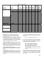
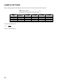
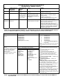
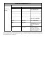
16-3004-101
Instruction Manual
ROM SUMMARY
ROM
PART NO.
DESCRIPTION
LOC.
BOARD
SINISTAR 1B
A-5343-09961-A
PROM, 4Kx8, REV 1 (Brown)
1D
ROM
SINISTAR 2B
A-5343-09962-B
PROM, 4Kx8, REV 1 (Brown)
1C
ROM
SINISTAR 3B
A-5343-09963-B
PROM, 4Kx8, REV 1 (Brown)
1A
ROM
SINISTAR 4B
A-5343-09964-B
PROM, 4Kx8, REV 1 (Brown)
2D
ROM
SINISTAR 5B
A-5343-09965-B
PROM, 4Kx8, REV 1 (Brown)
2C
ROM
SINISTAR 6B
A-5343-09966-B
PROM, 4Kx8, REV 1 (Brown)
2A
ROM
SINISTAR 7B
A-5343-10150-B
PROM, 4Kx8, REV 1 (Brown)
3D
ROM
SINISTAR 8B
A-5343-09968-B
PROM, 4Kx8, REV 1 (Brown)
3C
ROM
SINISTAR 9B
A-5343-09969-B
PROM, 4Kx8, REV 1 (Brown)
3A
ROM
SINISTAR 10B
A-5343-10153-B
PROM, 4Kx8, REV 1 (Brown)
4C
ROM
SINISTAR 11B
A-5343-09971-B
PROM, 4Kx8, REV 1 (Brown)
4A
ROM
Special Chip 1
A-5410-09911
Special Chip
1F & 2F
ROM
Decoder ROM 4
(Horizontal)
A-5342-09694
PROM, 512x8
3C
CPU
Decoder ROM 6
(Vertical)
A-5342-09821
PROM, 512x8
3G
CPU
ROM 13A (Sound) A-5343-10209
PROM, 4Kx8
IC12
SOUND
ROM 14A (Speech) A-5343-10199
PROM, 4Kx8
IC4
SPEECH
ROM 15A (Speech) A-5343-10200
PROM, 4Kx8
IC5
SPEECH
ROM 16A (Speech) A-5343-10201
PROM, 4Kx8
IC6
SPEECH
ROM 17A (Speech) A-5343-10201
PROM, 4Kx8
IC7
SPEECH
*ROM 18A (Sound) A-5343-10140
PROM, 4Kx8
IC12
SOUND
*Used on rear sound boards in Cockpit Games only.
INSTRUCTION MANUAL
FOR
UPRIGHT AND COCKPIT GAMES
including …
• operation
• bookkeeping
• adjustments
• diagnostics
• parts
1
CONTENTS
• CHAPTER 1 Game Setup
Warnings & Notices . . . . . . . . . . . . . . . . . . . . . . . . . . . . . . . . . . . . . . . . . . . . . 5
Game Features . . . . . . . . . . . . . . . . . . . . . . . . . . . . . . . . . . . . . . . . . . . . . . . . 5
Examine your Game . . . . . . . . . . . . . . . . . . . . . . . . . . . . . . . . . . . . . . . . . . . . 6
Location of Controls . . . . . . . . . . . . . . . . . . . . . . . . . . . . . . . . . . . . . . . . . . . . 6
• CHAPTER 2 Game Operation
Power Turn-On . . . . . . . . . . . . . . . . . . . . . . . . . . . . . . . . . . . . . . . . . . . . . . . . 8
Game Operation . . . . . . . . . . . . . . . . . . . . . . . . . . . . . . . . . . . . . . . . . . . . . . . 8
Bookkeeping Totals . . . . . . . . . . . . . . . . . . . . . . . . . . . . . . . . . . . . . . . . . . . . 9
Game Adjustments . . . . . . . . . . . . . . . . . . . . . . . . . . . . . . . . . . . . . . . . . . . . . 9
Definitions of Pricing Terms . . . . . . . . . . . . . . . . . . . . . . . . . . . . . . . . . . . . . . 10
• CHAPTER 3 Troubleshooting Procedures
Introduction . . . . . . . . . . . . . . . . . . . . . . . . . . . . . . . . . . . . . . . . . . . . . . . . . . . 14
Power-Up Tests . . . . . . . . . . . . . . . . . . . . . . . . . . . . . . . . . . . . . . . . . . . . . . . 14
+5v DC Power Supply Adjustments . . . . . . . . . . . . . . . . . . . . . . . . . . . . . . . . 15
Self-Diagnostics . . . . . . . . . . . . . . . . . . . . . . . . . . . . . . . . . . . . . . . . . . . . . . . 15
Diagnostic Mode Tests . . . . . . . . . . . . . . . . . . . . . . . . . . . . . . . . . . . . . . . . . . 16
Sound Board Diagnostics . . . . . . . . . . . . . . . . . . . . . . . . . . . . . . . . . . . . . . . . 18
CMOS RAM Data Test Protocol . . . . . . . . . . . . . . . . . . . . . . . . . . . . . . . . . . . 20
• CHAPTER 4 Parts Location
2
CHAPTER 1 Game Setup
Warnings & Notices
Game Features
Examine your Game
Location of Controls
3
4
Warnings & Notices
Game Features
WARNING:
49-WAY OPTO-JOYSTICK
1. FOR SAFETY AND RELIABILITY, WILLIAMS does
not recommend or authorise any substitute parts or
modifications of WILLIAMS Equipment.
MODELLED AFTER A MILITARY AIRCRAFT JOYSTICK,
the SINISTAR upright and cockpit joystick is engineered to
fit the hand and provide quick game response as well as
durability. Mini games have the space saving standard
joystick but retain the new opto technology.
2. USE OF NON-WILLIAMS PARTS and modification of
game circuitry may adversely affect game play, or may
cause injuries.
3. SUBSTITUTE PARTS, MODIFICATIONS AND GAME
"CONVERSIONS" may void FCC type-acceptance.
4. SINCE THIS GAME IS PROTECTED by Federal
copyright, trademark and paten laws, so-called game
"conversions" may be illegal under Federal law.
5. THIS "CONVERSION" PRICIPLE ALSO APPLIES to
unauthorised facsimiles of Williams equipment, logos,
designs, publications assemblies and games (or game
features not deemed to be in the public domain),
weather manufactured with Williams components or
not.
RF INTERFERANCE NOTICE:
CABLE ROUTING PLACEMENTS AND GROUND STRAP
ROUTING on this game has been designed to keep RF
radiation and conduction within levels accepted by FCC
regulations.
TO MAINTAIN THESE LEVELS, reposition harnesses and
reconnect ground straps to their original placements if they
should be disconnected during maintenance.
ELECTRONINCALLY THE JOYSTICK IS UNIQUE. Six
opto-isolators (three on the X -axis and three on the
Y-axis) are positioned to accept both direction and speed
cues. A resolution of 49 directions and speed combinations
is possible. See PLYER CONTROLS below.
STEREO COCKPIT SOUND
FOR THE FIRST TIME IN A WILLIAMS GAME we've
included stereo sound!
The new cockpit-style cabinet
sufficiently encloses the player so that stereo sound will
enhance the game experience.
TRUE STEREO. Since "true" stereo requires two sound
sources, the SINISTAR cockpit game has not only two
speakers, but two entire sound boards ... complete with two
separate volume controls for maximum operator control!
SINISTAR SPEAKS!
CHALLENGE FROM A STAR. Just as the SINISTAR
character is no mere twinkle on the night horizon, this is no
ordinary video game! The SINISTAR character is the
archvillian players love to hate. One of the best reasons
why is that he dares them to challenge him!
ALL HIS WORDS ARE STORED IN ROM. A SINISTAR
sound board addresses ROM chips on a separate speech
board to access digitally-stored phrases. These phrases
are converted from parallel to serial from on the sound
board and then fed back to the speech board.
THE SPEECH BOARD THEN TRANSLATES incoming
digital pulses into analogue form and filters the resulting
analogue speech. Next the speech is mixed with the sound
effects stored and D/A converted to the sound board.
Finally the speech and effects travel back to the sound
boards power amplifier chip and out of the speaker.
5
Examine Your Game
Location of Controls
When you receive a new WILLIAMS game, examine it
carefully before you power it up. Be sure that it was
delivered in good condition!
THE ON-OFF SWITCH is situated on the top left corner of
upright games as you face the back of the cabinet. Cockpit
games have an on-off switch beneath the cashbox door.
The switch is positioned in the floor of the games front end.
INSPECT THE OUTSIDE of the shipping carton
and/or game cabinet for shipping damage.
UPRIGHTS & MINIS: UNLOCK AND SET ASIDE THE
TOP REAR PANEL. Undo the two trunk latches on the
inside of the bottom door. Open the door. Now check
circuitry.
COCKPIT GAMES: (1) Unlock the cashbox door on the
front of the game. (2) Now remove the cashbox and
extend your arm to the left and right inside the door.
Undo the two hood trunk latches. (3) Raise the hood.
(4) Loosen the two access screws on the right side of
the PC board panel. (5) Swing the panel up and to the
left to inspect circuitry.
ARE THE CONNECTORS SECURELY ATTACHED?
Reconnect any found loose.
DON'T FORCE
CONNECTORS. They're keyed and only fit one way.
By the same token take care: reversed edgeconnectors can damage PC boards.
ARE PLUG IN CHIPS FIRMLY-SEATED in their
sockets?
UNWRAP THE POWER CORD coiled inside the
cabinet. Now position the cord in the wood slot
beneath the bottom door. (cockpit games: Drop the
plug through the hole in the floor. This hole is near the
front of the game and under the PC board panel.)
DON'T PLUG IN YET!
SCRUTINIZE MAJOR SUBASSEMBLIES, such as the
monitor, control panel, transformer board and power
supply. Make sure they're securely-mounted.
THE VOLUME CONTROL in upright games is located
inside the coin door and on the right cabinet wall as you
face the game.
THE COCKPIT GAME HAS TWO VOLUME CONTROLS,
one for each sound board. These controls are located near
circuit boards under the games hood (below the hinged
panel underneath the hood).
DIAGNOSTIC SWITCHES are on the back of the coin door
in upright games. In cockpit games they're under the hood
and on the top-right side as you face the front of the game.
These switches are used to access the Diagnostic-Mode
tests, the BOOKKEEPING TOTALS screen and the GAME
ADJUSTMENTS screen. Refer to the appropriate sections
below for information on these important features.
OTHER CONTROLS. Finally they are five more controls
that are used somewhat less often than those above:
(1) The memory-protect interlock switch is near the
diagnostic switch bracket (see above). This switch must be
open when you clear BOOKKEEPING TOTALS or make
GAME ADJUSTMENTS. It automatically opens when the
coin door is open on upright or mini games and when the
hood is open on cockpit games.
(2) The CPU board reset switch is located across the
CPU board from the batteries.
(3) The Cashbox advance switch, found inside the
cashbox door on all models, allows bookkeeping
information to be audited without permitting it to be zeroed.
(4) The sound/speech mixer pot permits the operator to
balance sound/speech to suit his location. This pot is on
the speech board on all games.
6
CHAPTER 2 Game Operation
Power Turn-On
Game Operation
Bookkeeping Totals
Game Adjustments
Definitions of Pricing Terms
7
Power Turn-On
PRESS FIRE! The spaceship fires at planetoids and also
enemy Workers and Warriors.
CAUTION: This game must be plugged into a properly
grounded outlet to prevent shock hazard and to ensure
proper game operation. DO NOT use a "cheater" plug to
defeat the ground pin on the line cord, and DO NOT cut off
the ground pin.
PRESS SINIBOMB! When your Sinibomb is made with
ore from the planetoid, you may press the Sinibomb
button to destroy the Sinistar.
WHEN THE GAME IS FIRST TURNED ON it produces a
sound. Simultaneously general illumination should come
on and a moment later a scanning “rug pattern”' indicating
the RAM test should appear on the screen. Next the rug
should become stationary as the ROM test is performed.
In a correctly running game the rug pattern will be followed
by the message "INITIAL CHECKS INDICATE ALL
SYSTEMS GO". If RAM or ROM failure messages come
up on the screen instead, refer to Power-Up Tests in
TROUBLESHOOTING PROCEDURES.
Game Operation
GAME START
Insert coins; a random sound is produced and credits are
displayed on the CRT. With two or more credits displayed,
pressing 2-player start initiates a 2-player, *3-turn game.
PLAYER CONTROLS
CONTROLLED BY THE JOYSTICK, a unique
configuration of optoswitches provides a faster response
and a greatly increased number of vectors in each
quadrant for the precise aiming of your space ship.
TWO SETS OF THREE OPTOSWITCHS are each
arranged at right angles to each other. One set is for
aiming along the X-axis; the other is for aiming along the
Y-axis. With the joystick in the centre position all six are
blocked.
AS THEY JOYSTICK IS ADVANCED or pulled back it
actuates one or both sets of switches. The spaceship
responds with extraordinary precision due to the sequential
action of the optoswitches in each set. Each switch in the
set is offset so that the joystick action multiplies the circuitry
brought in by the switches, increasing the precision action
of the spaceship.
THE SPACESHIP ACCELERATES as the joystick is
moved further from the centre position; it decelerates as
the joystick is pulled or pushed back toward the centre
position.
SPECIAL CIRCUITRY is included for the spaceship to
respond immediately to sudden reversals of joystick
movement.
8
GAME PLAY
***YOUR INTERGALACTIC CRYSTAL-MINING MISSION
takes you to the antipodes of the known universe. But your
parametric DeepSpace scanner faithfully displays the
sector of the galaxy you presently occupy (including an
area fully 3 parsecs across, no less)!
***KEEP THE GALAXY SAFE for all it's sinizens! Fiendish
Worker ships from the planet Sporg will attempt to
fabricate a Sinistar from the remains of derelict planetoids
in your very sector. You must not let them do this for two
reasons:
(1) These planetoids contain the life-sustaining crystals
that your civilisation requires for it's vital technologies.
(2) With the eminently unstable Sinistar in their
possession, the Sprogites can lay waste to any civilisation
in your sector. You alone stand in their way.
***YOU MUST MINE THE SINISITE CRYSTALS. Williams
has equipped you with the latest heuristic electret cannon
technology. All you need to do is aim at a planetoid and
shoot. Now collect your motherlode!
***IN FACT, ONLY WITH SINISITE CAN YOU MANUFACTURE SINIBOMBS to eradicate the Sinistar. But you
must also rebuff the Workers and disintegrate their even
more aggressive comrades-at-arms, the evil skelomorphic
Warriors! Intelligent beings everywhere depend on your
courage, your dedication, your reserve, your shrewd
command of tactical invention! It's up to you space cadet!
HIGH SCORE SIGNATURE
Select letters with the joystick. Push right to move forward
through the alphabet; push left to move backward. Then
push the FIRE button to lock in the letter.
________________
*Adjustable Feature
Bookkeeping Totals
Clearing Bookkeeping Totals
1. In Game-Over Mode, open the cashbox and depress
the cashbox advance switch. The advance switch
located on the diagnostic switch bracket can also be
used. (See Figure 1.) The CRT should indicate all
bookkeeping and evaluation totals. If so, go to step 3.
If the CRT display comes up in the ROM test, perform
step 2.
1. Depress ADVANCE to display Game Adjustments.
2. Operate joystick Up or Down to position cursor on
CLEAR BOOKKEEPING TOTALS.
3. Push FIRE Button.
4. Depress ADVANCE.
AUTO-UP
HIGH
SCORE
RESET
MANUAL
DOWN
ADVANCE
Figure 1. Coin Door Button Switches
2. Continue to depress the cashbox advance switch,
stepping the game through test programs for ROMs,
RAMs, CMOS RAMs, colour RAMs, sounds, switches,
and then CRT test patterns, of which there are five.
The fifth test pattern, colour bars, directly precedes the
CRT display of the bookkeeping and evaluation totals.
3. The bookkeeping and evaluation totals appear on the
displays as in Figure 2.
IF AVERAGE TIME PER CREDIT RUNS BELOW 1:30
(Figure 2), then more liberal GAME ADJUSTMENTS are
recommended. What if AVERAGE TIME PER CREDIT
runs over 2:30? Make the game tougher. Always try to
keep AVERAGE TIME PER CREDIT close to the ideal of
2:00.
Game Adjustments
In the Game-Over Mode open the coin door. With the
AUTO-UP/MANUAL-DOWN switch set to AUTO-UP, and
depress the coin door ADVANCE switch twice to cause
a CRT display as shown in Figure 3.
SELECT THE FUNCTION YOU WISH to change by
moving the joystick (push up to move arrow up, down to
move arrow down) Then, making sure the coin door is
open, push the FIRE button to increase or SINIBOMB t to
reduce the value of the selected function.
Select the appropriate difficulty level by using the
SINIBOMB (easier) and FIRE (harder) buttons (0 =
easiest or liberal, 5 = average, 9 = hardest or
conservative). NOTE: The next two adjustments affect
playing time by making extra ships easier or harder to
win. Details are on page 12.
BOOKKEEPING TOTALS
For a shorter game, increase the bonus points figure
(FIRST EXTRA SHIP AT). For a longer game, reduce
it. (1,000 = long / 99,000 = short).
LEFT SLOT COINS
CENTER SLOT COINS
RIGHT SLOT COINS
PAID CREDITS
FREE SHIPS
TOTAL TIME IN MINUTES
TOTAL SHIPS PLAYED
TOTAL CREDITS PLAYED
AVERAGE TIME PER CREDIT
167
0
426
23
221
1200
2000
593
2:01
For a shorter game, increase ADDITIONAL POINTS
PER SHIP AT. For a longer game, decrease it. (1,000
= long / 99,000 = short).
For a shorter game, decrease the number of SHIPS
PER GAME. For a longer game, increase the number.
(1 = short / 99 = long).
GAME PRICING is selected with standard settings or with
custom settings as shown in Table 1. Note that free play
can be elected by entering the code number 9 at the
PRICING SELECTION function.
FOR STANDARD SETTINGS you need change only the
PRICING SELECTION. For custom settings, first set
PRICING SELECTION to zero and then set the remaining
values according to Table 1.
Figure 2. Bookkeeping Display
9
GAME ADJUSTMENTS
FIRST EXTRA SHIP AT
30,000
ADDITIONAL EXTRA SHIP
POINTS FACTOR
30,000
SHIPS PER GAME
3
DIFFICULTY OF PLAY
5
YES
CONTINUOUS FIRE
HIGH SCORE TO DATE
YES
ALLOWED
PRICING SELECTION
3
LEFT SLOT UNITS
1
CENTER SLOT UNITS
4
RIGHT SLOT UNITS
1
UNITS REQUIRED FOR CREDIT
1
UNITS REQUIRED FOR BONUS
CREDIT
0
MINIMUM UNITS FOR ANY
CREDIT
0
RESTORE FACTORY SETTINGS
NO
CLEAR BOOKKEEPING TOTALS
NO
HIGH SCORE TABLE RESET
NO
AUTO CYCLE
NO
USE ‘MOVE’ TO SELECT
ADJUSTMENT
USE ‘FIRE-SINIBOMB’ BUTTONS TO
CHANGE THE VALUE
PRESS ADVANCE TO EXIT
Figure 3. Game Adjustments
Showing factory settings
HIGHEST SCORE SIGNATURE
SETTING ATTRACT MODE MESSAGE
The number of letters allowed the highest scoring player for
entering his name can be varied from 3 to 20 and is
recommended as 3. If objectionable words are entered as
the signature name, you can change the lettered entry
leaving the highest score the same. See SETTING
HIGHEST SCORE NAME.
1.
2.
3.
4.
RESTORE FACTORY SETTINGS
1. Position cursor on RESTORE FACTORY SETTINGS.
2. Push FIRE button.
3. Depress ADVANCE twice.
RESETTING HIGH SCORE TABLE
1. Position cursor on RESET HIGH SCORE TABLE.
2. Push FIRE button.
3. Depress ADVANCE.
10
Position cursor on SET ATTRACT MODE MESSAGE.
Push FIRE button.
Depress ADVANCE.
Enter up to two lines of your message following
instructions on the screen
5. Depress ADVANCE to terminate process.
To restore the Williams attract mode message, perform
steps 1 through 3 and then turn the game OFF and back
ON.
SETTING HIGH SCORE NAME
1.
2.
3.
4.
Position cursor on SET HIGHEST SCORE NAME.
Push FIRE button.
Depress ADVANCE.
Enter new signature; depress ADVANCE to terminate
process.
An alternate, simpler method enters the factory highest
score signature. In the game over mode, hold HIGH
SCORE RESET Depressed. After a few seconds a sound
is produced and the factory highest score signature has
been activated.
Table 1. Game Pricing
Pricing
Selection
Left
Slot
Units
Centre
Slot
Units
Right
Slot
Units
Units
Per
Credit
Units
Req'd
For
Bonus
Credit
Min
Units
For
Any
Credit
Coin Door
Credits/
Mechanism
Money
Twin Quarter
Quarter, Dollar, Quarter
•
•
•
•
•
•
•
•
•
1/25¢, 5/$1
2/50¢, 5/$1
1/25¢, 4/$1
2/50¢, 4/$1
1/50¢, 3/$1, 4/$1.25
1/50¢, 3/$1, 7/$2
1/50¢, 3/$1, 6/$2
1/50¢
1/1DM, 6/5DM
0
0
3
0
0
0
1
5
2
1
1
1
1
3
12
1
1
6
4
4
4
4
12
48
4
4
0
1
1
1
1
3
12
1
1
1
1
1
1
1
4
14
2
2
1
4
4
0
0
15
96
4
0
0
0
2
0
2
0
24
0
0
0
•
•
•
•
•
•
•
•
•
•
•
•
•
•
•
1/20¢, 3/50¢
1/2F, 3/5F
1/25¢, 4/1G
1/25¢, 5/1G
1/5F, 2/10F
1/10F
2/1F 5/2F
1/200 Lire
1/1 Coin
1/2 Coins
1/3 Coins, 2 5 Coins
1/2, 3/5
1/1, 5/5
1/3, 2/5
Free Play
0
4
6
6
4
1
0
16
0
15
6
4
5
2
1
0
0
0
0
0
0
0
7
8
2
8
3
5
0
4
0
0
9
1
1
1
6
1
1
1
2
1
1
2
1
0
0
0
0
0
4
4
0
16
0
0
4
4
2
2
1
2
1
1
2
6
5
10
1
1
1
2
1
2
1
2
5
2
1
5
1
4
0
0
0
0
0
0
0
0
0
0
0
0
0
0
0
0
0
0
0
0
0
0
0
1DM, 5DM
20-Cent, 50-Cent
1 Franc, 5 Franc
25 Cent
1 Guilder
5 Franc
10 Franc
1 Franc, 2 Franc
100 Lire, 200 Lire
Twin Coin
1-Unit, 5-Unit
Any
Definitions of Pricing Terms
PRICING SELECTION allows a shorthand method of
setting the pricing functions. If a number from one to nine
is entered into the PRICING SELECTION function, a
corresponding standard setting (shown in bold type above)
will be entered into the game. The rest of the pricing
functions are automatically set for that standard.
THE PRICE OF ONE GAME (number of coins per game) is
equal to the number of SLOT UNITS for any one slot
divided by the number of UNITS PER CREDIT. If the
number of LEFT SLOT UNITS (or RIGHT SLOT UNITS)
equals X and the number of UNITS PER CREDIT equals
Y, then the price of one game is X/Y
For example if an operator wants to allow one play for a
quarter but wishes to encourage multiple game playing, he
may enter:
• "0" in the PRICING SELECTION function
This zero value automatically sets all pricing functions.
However minimum units for any credit must be raised to "2"
or higher value to achieve the operators goal. Here are the
rest of the functions as they should appear.
•
•
•
•
•
UNITS REQUIRED FOR BONUS CREDIT is the number of
games that must be purchased before a free game is
awarded.
"1" in the LEFT SLOT UNITS function
"4" in the CENTER SLOT UNITS function
"1" in the RIGHT SLOT UNITS function
"1" in the UNITS PER CREDIT function
"0" in the UNITS REQUIRED FOR BONUS
CREDIT function
• "2" in the MINIMUM UNITS FOR ANY CREDIT
function
MINIMUM UNITS FOR ANY CREDIT is the least number
of coins allowed per game or games. Or put another way,
the MIMIMUM UNITS FOR ANY CREDIT determines the
smallest number of whole games that may be paid for at
one time.
These values allow one game to be played for a quarter,
but ONLY when two or more games are paid for at a time.
Incidentally, the "4" in the CENTER SLOT UNITS allows
four games per dollar coin (centre slot only). See "2/50¢,
4/$1" above.
11
SAMPLE SETTINGS
Before adjusting EXTRA SHIPS settings, review the chart to see how they affect the extra ship score.
LET
FIRST EXTRA SHIP AT
=F
ADDITIONAL EXTRA SHIP POINTS FACTOR = A
EXTRA
SHIP
1st
2nd
3rd
4th
5th
1
This series is derived from:
nF +
(n2-n)A
2
where n is the extra ship no.
12
1
FORMULA
F
2F + 1A
3F + 3A
4F + 6A
5F + 10A
F = 10,000
A = 0000
10,000
20,000
30,000
40,000
50,000
F = 10,000
A = 10,000
10,000
30,000
60,000
100,000
150,000
F = 30,000
A = 10,000
30,000
70,000
120,000
180,000
250,000
F = 10,000
A = 30,000
10,000
50,000
120,000
220,000
350,000
CHAPTER 3 Troubleshooting Procedures
Introduction
Power-Up Tests
+5v DC Power Supply Adjustments
Self-Diagnostics
Diagnostic Mode Tests
Sound Board Diagnostics
CMOS RAM Data Test Protocol
13
INTRODUCTION
Certain types of game malfunctions may inhibit the game's
diagnostic or display faculties. Troubleshooting procedures for
most of these types of malfunctions as well as malfunctions that
permit self-diagnosis are covered below. Our troubleshooting
algorithm begins with Power-Up and continues until Game Over
Mode.
All procedures can be performed with minimal test
equipment or merely by observing the game itself.
POWER-UP TESTS
NO GENERAL
ILLUMINATION
NO INITIAL VIDEO
(RUG PATTERN)
CHECKING POWER
SUPPLY BOARD
(1) Check fuse F2 on power supply board.
(2) Check for proper installation of jumpers
W1, W2, W3 and/or resistor R27. (Some
machines DO NOT have an R27. Refer to
your drawing set.)
(3) Check 4P1/J I, 4P3/J3, 6P2/J2 and
6P3/J3.
(4) If all the above don't turn up the problem
check power supply board.
(1) Press reset button on CPU Board.
(2) Try RAM and ROM tests (see below)
(3) If all the above don't turn up the problem,
check power supply board.
(1) Swap power supply board with one from
known-good game.
(2) If game plays, problem is on power
supply board.
(3) If game doesn't play, check power
transformer with voltmeter.
(4) If known-good power supply is
unavailable for tests above, check +5V, –
5V and + 12V outputs on power supply in
game. Each MUST BE within 2% of rated
output with less than 0.1% AC hum.
MORE POWER-UP TESTS
TEST
ROM BOARD
LEDs RECOGNIZE
CONDITION
GENERAL
“0” means all
power-up tests
passed
CMOS (See
Appendix A)
“0” means tests
passed
-
“0” means tests
passed
-
BATTERY (See
Appendix A)
“0” means tests
passed
-
“HIGH SCORE TABLE RESET”
“BOOKKEEPING TOTALS CLEARED”
“ADJUSTMENT FAILURE”
“RESTORE FACTORY SEITINGS
BY OPENING FRONT AND
TURNING GAME OFF AND ON”
MEMORY
PROTECT
INTERLOCK
(See
Appendix A)
“0” means tests
passed
-
SPECIAL CHIP
“0” means tests
passed
-
“HIGH SCORE TABLE RESET”
“BOOKKEEPING TOTALS CLEARED”
“ADJUSTMENT FAILURE”
“RESTORE FACTORY SEITINGS
BY OPENING FRONT AND
TURNING GAME OFF AND ON”
(1) Scanning rug pattern.
(2) Blank screen instead of “INITIAL
TESTS INDICATE: OPERATIONAL”
(3) High score table with no scores.
(4) Intro blank or program crash.
14
ROM BOARD LEDs
IDENTIFY BAD
CHIPS
-
VIDEO
REMEDY
(1) Scanning rug pattern
(2) Stationary rug pattern
(3) "INITIAL TESTS INDICATE ALL
SYSTEMS GO"
(4) Game-Over Mode
“HIGH SCORE TABLE RESET”
“BOOKKEEPING TOTALS CLEARED”
“ADJUSTMENT FAILURE”
“RESTORE FACTORY SEITINGS
BY OPENING FRONT AND
TURNING GAME OFF AND ON”
“FACTORY SEITINGS RESTORED”
If any video (see left) is missing or
error message is displayed,
proceed to Diagnostic Mode
tests.
(1) Open coin door and turn
power off and on.
(2) Press ADVANCE. Game
should return to Game-Over
Mode.
(1) Open coin door and turn
power off and on. Or press
ADVANCE. In either case, game
should return to Game-Over
Mode.
(2) Check AA alkaline cells on
CPU Board.
(3) If problem persists proceed
with CMOS RAM test by putting
the game into its Diagnostic
Mode (see SELFDIAGNOSTICS).
(1) Making and breaking coin
door interlock switch, check with
VOM and replace if faulty.
(2) Replace if faulty: Memory
protect gates 6E, IC1, Ql, or
CMOS RAM 1C.
(1) Turn power off.
(2) To find bad chip replace 2
special chips one at a time with
known good chips.
(3) Turn Machine on after each
replacement and run through
Power-Up Tests.
Figure 4. RAM Location and Numbering on the CPU Board & ROM Board RAMs
+5v DC Power Supply
Adjustments
a ROM test is performed. With ROM test results present
on the CRT display, depressing the ADVANCE pushbutton
initiates the RAM test.
Before adjusting the voltage output, always check the
output at the supply for AC hum. This hum should never
rise above 0.005v on the +5v DC supply. If it does, consult
your schematic drawing set for proper DC voltages
throughout the circuit.
Further tests (CMOS, sound, switch, colour RAM, monitor
test patterns) are encountered one after the other as the
ADVANCE pushbutton is depressed (once more for each
subsequent test).
Test for these with the DC setting of your multimeter. Make
a second check using the AC setting. Pay particular
attention to readings at TP5 (top of capacitor C10). If the
voltage here is too low (less than +11v DC) or you find
excessive ripple (more than 700mv rms), replace the
capacitor.
If TP1 is less than +4.95v DC remove R10. If TP1 is still
less than +4.95v DC, the check precision resistors R25 and
R26. If they are within 1% tolerance, the check IC2.
Self-Diagnostics
If RAM or ROM failure messages are displayed on the CRT
after the “rug pattern” proceed with self-diagnostics. Selfdiagnostic procedures are controlled by the AUTOUP/MANUAL-DOWN and ADVANCE switches in the coin
door. (See Figure 1.)
Set the AUTO-UP/MANUAL-DOWN switch to the
MANUAL-DOWN position and depress the ADVANCE
pushbutton. The game is now in its Diagnostic Mode and
MONITOR TEST PATTERNS (19" Monitor Upright Games
Only). For ease in monitor adjustments, the monitor may
be slid back and the screen viewed in the CRT mirror
provided on the inside-top of the cabinet.
Remove the two bolts and carefully slide the monitor back
in its shelf; secure the monitor in the extended position by
inserting the two bolts though holes in the monitor base
and monitor shelf provided at the left side of the monitor.
AUTO CYCLE MODE - From the colour bar pattern (or
Game Over with the switch set to AUTO-UP) depress
ADVANCE two times to display GAME ADJUSTMENTS.
1. Position the cursor on AUTO CYCLE with the Joystick
and push the FIRE button.
2. Depress ADVANCE.
3. The system will now sequence through ROM, RAM,
and CMOS RAM tests repeatedly. The coin door must
be open during the Auto Cycle test. If an error is
detected, the test is terminated and the failure
indication is displayed on the CRT.
4. To terminate the Auto-Cycle test, turn the game OFF
and ON.
15
TROUBLESHOOTING PROCEDURES:
DIAGNOSTIC MODE TESTS
TEST
ROM BOARD LEDs
IDENTIFY
CHIPS
2-digit ROM chip
number
VIDEO
REMEDY
ROM
ROM BOARD LEDs
RECOGNIZE
CONDITION
“2” means ROM error
“ROM ERROR” and ROM chip
number.
(1) Turn power off.
(2) Replace suspected chip.
RAM
“1” means RAM error
Bank number first,
then chip number in
bank (see figure 4)
*(For RAM Error 41
or 42 See Note)
“RAM ERROR” followed by
RAM bank number and chip
number (Note: with multiple
RAM failures this display may
not appear)
-
“CMOS RAM ERROR OR
WRITE PROTECT FAILURE”
CMOS (See
Appendix A)
“3” means CMOS
RAM error
* (1) Check for normal voltages on indicated
RAM chip: -5v/pin 1, +12v/pin 8, +5v/pin 9.
(2) Turn power off.
(3) Replace suspected chip.
(4) With multiple RAM failures always check
power supply. See POWER-UP TESTS.
(1) Check pin 22 of CMOS RAM for +3.2VDC
minimum. If present, replace CMOS chip 1C. If
absent replace AA alkaline cells.
(2) With new alkaline cells, check for +3.8v DC.
If still absent, replace diodes D9 and D10.
(3) Upon power-up and re-entry into diagnostics
if CMOS error message persists, check CMOS
RAM memory protect and address decoding
circuits with a logic probe.
Tests 4 and 7 provide sequential subtests. To stop automatic cycling set switch to MANUAL-DOWN. Depress
advance in MANUAL-DOWN to step through subtests. LED indications are not made for these tests.
TEST & PROCEDURES
VIDEO
SOUND
(Test 4)
“SOUND LINE 1”
“SOUND LINE 2”
“SOUND LINE 3”
“SOUND LINE 4”
“SOUND LINE 5”
“SOUND LINE 6”
(These appear one at a time)
SWITCH TEST
(Test 5)
(1) Set switch to MANUAL-DOWN
and clear any stuck switches.
(2) CRT should indicate no
switches closed.
(3) Operate switches and check
for display of switch name.
CRT indicates AUTO-UP closed and any stuck
switches. CRT Display for Each Switch . . .
ROM BOARD
INTERFACE BOARD
ADVANCE
1- PLAYER START
AUTO-UP
2- PLAYER START
HIGH SCORE
UP-DOWN A1
RESET
UP-DOWN B1
LEFT COIN
UP-DOWN C1
CENTRE COIN
UP-DOWN DIRECTION 1
RIGHT COIN'
RIGHT-LEFT A1
SLAM SWITCH
RIGHT-LEFT B1
RIGHT-LEFT C1
RIGHT-LEFT DIRECTION 1
FIRE 1
SINIBOMB 1
REMEDY OR ADJUSTMENT
Missing
1
2
3
4
5
6
All
Check
2P4/lOP3 Pin 3
2P4/10P3 Pin 2
2P4/10P3 Pin 5
2P4/10P3 Pin 4
2P4/10P3 Pin 7
2P4/10P3 Pin 6
Perform Sound Board Diagnostics
(see below)
NOTE: If any two sounds are the same, check for
a short between the select lines with the same
sound.
(Refer to CABINET WIRING Diagram)
(1) COIN DOOR SWITCH STUCK: Disconnect
2P3
(2) PLAYER PANEL SWITCH STUCK:
Disconnect 3P2 or 3P3
(3) COIN DOOR SWITCH DOES NOT
OPERATE: Ground corresponding pin of 2P3.
(4) PLAYER PANEL SWITCH DOES NOT
OPERATE: Ground corresponding pin of 3P2 or
3P3
SYMPTOM REMAINS SAME . . .ROM Board or
Interface Board Faulty.
SYMPTOM CLEARS UP . . .Problem is in
switches or wiring
ADDITIONAL TESTS FOR OPTOSWITCHES:
(5) Check that +5v DC is at pin 1 or 12P1.
(6) With joystick in centre position, check for 0.7v
at base of ON transistor(s) (Q1 thru Q6) and 0.1v
at pin(s) 2, 3, 4, 6, 7 and 8 of 12P1
(7) With joystick moved from centre position,
check for 0.1v at base of OFF transistor(s) and 5v
at pin(s) 2, 3, 4, 6, 7 and 8 of 12P1
(8) With joystick in centre position, check for 5v at
pin(s) 5 and 9 of 12P1. With Joystick in Down
(Left) position, check for +5v at pin 5 (9) of 12P1.
With Joystick in Up (Right) position, check for +0v
at pin 5 (9) of 12P1.
NOTE: Two static RAMs located on the ROM board are indicated as RAM 41 in chip location 6D and RAM 42 in
chip location 4D.
MORE DIAGNOSTIC MODE TESTS
TEST & PROCEDURES
COLOUR RAM TEST
(Test 6)
Note that a blank sequence or two sequences with the
same shade indicate a faulty 1A flip-flop, 1B RAM or 2B
RAM or a failure in the colour analogue circuit. Check
voltages on Q1 (green transistor), Q2 (red transistor) and
Q3 (blue transistor). During the eight full screen colour
tests, the base voltage (centre Pin) on each transistor
should vary between 3.8v (brightest colour) and 4.4v (no
colour)
Colour RAM check
(1) CRT sequences through 8
colours, 2 seconds each
(2) Thick vertical band
indicates colour RAM fault.
MONITOR & COLOUR RAM TEST
(Test 7)
MAGENTA
CYAN
YELLOW
WHITE
BLACK
BLUE
GREEN
RED
Colour Bar Pattern
VIDEO SEQUENCES
REMEDY OR ADJUSTMENT
REPLACE RAM 1B REPLACE RAM 2B
1) light red screen
2) red screen
3) dark red screen
too-light or
too-dark red
or grey band
magenta band
4) light green screen
5) green screen
6) dark green screen
yellow band
cyan band
7) light blue screen
8) blue screen
magenta band
too-light or too
-dark blue or
grey band
4) light green screen
green band
dark green band
or grey band
5) green screen
light green band
dark green band
or grey band
6) dark green screen
-
grey band
cross hatch pattern
Aids you in setting up vertical and
horizontal linearity, convergence and focus.
red screen
green screen
blue screen
colour bars
Aids you in optimising colour purity
colour bars
• double-width
• half-width
• transposed
• missing
If colour RAM test 6 indicates no faults,
symptoms at left suggest a fault in 1A, 1B,
2B or 2C chips.
SOUND BOARD DIAGNOSTICS
SYMPTOM
MISSING SOUNDS
NO SOUND-STEP 1
(ASSUMPTION:
INPUT SECTION
FAILURE)
TEST & PROCEDURES
CHECK SOUND SELECT INPUTS
TEST
TOOL
CONDTION & REMEDY
Sound board connector
10P3/J3-2 to 7
Logic Probe (Game on
and in test 4)
• PULSING - Proceed.
• LOW - check jacks, foils.
• STILL LOW - Perform ROM
board checkbox below.
SR1 DIP resistors
R3 to R9
VOM - Reading ohms
(game off)
• ALL 4.7K - Proceed.
• ANY OPEN - replace SR1.
C3 to C9
VOM - Reading ohms
(game off)
• ALL OK - Proceed.
• ANY SHORTED - replace bad.
IC 5-1, IC 7-14
(power pins)
Logic Probe (Game on
and in test 4)
• HIGH - Proceed.
• LOW - Replace C19 (IC5) or C21
(IC7).
• STILL LOW - Replace bad IC.
IC5-2, 4, 6, 10, 12, 15
IC7-4, 6
Logic Probe (Game on
and in test 4)
• PULSING - Proceed.
• LOW - Replace bad chip.
IC10-18, 19
(PIA)
Logic Probe (Game on
and in test 4)
•
•
•
•
PULSING - Proceed.
LIFT C20 - Retest.
PULSING NOW - Replace C20.
STILL LOW - Replace IC6,
retest.
IC10-10 to 17
(PIA)
Logic Probe (Game on
and in test 4)
•
•
•
•
•
PULSING - Proceed.
SOME LOW Replace IC.
ALL LOW - Lift C31, retest.
PULSING NOW - Replace C31.
STILL LOW - Replace IC
NOTE: In cockpit model games where no sounds are produced from either sound board, disconnect both 9-pin connectors from
one board and then the other. This isolates faults to a single Sound Board. If sounds are still nit produced from either board
check ROM Board outputs on page 19 first.
SOUND BOARD DIAGNOSTICS
SYMPTOM
MISSING SOUNDS:
NO SOUND--STEP 2
(ASSUMPTION
OFF-BOARD
FAILURE)
NO SOUND
(ASSUMPTION:
POWER SECTION
FAILURE)
STILL NO SOUND
(ASSUMPTION:
AUDIO SECTION
FAILURE)
MISSING SOUNDS;
NO SOUND
(ASSUMPTION:
DIGITAL
FAILURE)
TEST & PROCEDURES
CHECK ROM BOARD OUTPUTS
(1) If you hear game sounds, disconnect and reconnect sound board connector 10P3/J3.
(2) You Should hear one or more game sounds. If so put the game in Diagnostic Mode
Test 4 and proceed with this checkbox. If not go ahead to POWER SUPPLY checkbox
below.
TEST
ROM board connector
2P4/J4-2 to 7
TOOL
logic probe (game on and
in test 4)
CONDTION & REMEDY
9C DIP resistors 2 to 8
VOM - Reading ohms
(game off)
• ALL 4.7K - Proceed.
• ANY OPEN - replace 9C.
C40-53
VOM - Reading ohms
(game off)
• ALL OK - Proceed.
• ANY SHORTED - replace bad.
8C-10 to 15 (PIA)
logic probe (game on and
in test 4)
• PULSING - Proceed.
• SOME LOW Replace 8C.
• PULSING - Repair cable to
sound board.
• ANY LOW - Replace jack or foil,
proceed.
CHECK ON-BOARD POWER SUPPLY
(1) With power off test for fuse continuity at F1 and F2.
(2) With power on check for +12v unregulated DC at TP1 and pin 5 of IC1.
(3) Now check for +5v regulated DC between TP4 and TP3. If voltages are absent or low
turn off game and lift one pin of filter capacitors C25, C26 and C27.
(4) Check each with ohmmeter for possible short circuits.
(5) If capacitors are good and unregulated voltages test okay but you’re missing +5v,
replace regulator chip (IC8).
CHECK AUDIO (ANALOG) SECTION
(1) Turn power on; turn up volume control. Momentarily place powered-up AC soldering
pencil on final amplifiers input pin (IC1, pin 1 or 10P4, pin 2) If you hear low hum, audio
IC, volume pot and speaker are okay.
(2) Repeat test at Q2 emitter. If you hear hum, analogue section is okay. Step (1) will also
work if you simply touch amplifiers input pin. However output level of hum will be much
lower than with soldering iron. DO NOT use a soldering pencil over 40 watts. Cordless
models will NOT work here.
CHECK SOUND ROM 12 AND RELATED CIRCUITRY
(1) Turn power on.
(2) If you have no game sounds but power supply tests show normal voltages and no ripple
on +5v, check crystal clock circuit. Using DVM or logic probe, test for pulsing AC across
crystal. If clock signal’s absent replace crystal and associated capacitors.
(3) Turn off power.
(4) Swap sound ROM (IC12) and microprocessor chip (IC9) with known-good chips.
(5) Power up and test Sound Board after each swap by pushing DIAGNOSTIC button.
CMOS RAM Data
Test Protocol
The first sub-test of the CMOS
RAM data is that of the
ATTRACT MODE MESSAGE
checksum. If the test does not
pass, the factory ATTRACT
MODE MESSAGE is restored.
Next, the game adjustments are
checked and restored to factory
settings if an error is found. If
game adjustments are found
intact, the high score table is
checked for any bad entries. Bad
entries are replaced with a score
of 4,000 points and no initials. If
all entries check, the game
returns to the Game Over Mode.
If game adjustments are restored
to factory settings, the AUDIT
TOTALS are checked. If 5 or
more audit digits are other than
0-9 (that is hexadecimal A
through F) all audit totals are
cleared. This is followed by a
check of the high score table and
the table is reset to factory
settings if errors are found.
Finally, game adjustments are
rechecked and either OPEN
COIN DOOR or FACTORY
SETTINGS
RESTORED
is
displayed. With the former, open
the coin door and turn the game
OFF and ON and then FACTORY
SETTINGS RESTORED will be
displayed. Return to game over
by depressing the ADVANCE
pushbutton or by turning the
game OFF and ON a second
time.
POWER ON
1
ATTRACT MODE
MESSAGE?
PASS
FAIL
RESTORE
FACTORY
MESSAGE
GAME
ADJUSTMENTS?
PASS
FAIL
RESTORE
FACTORY
SETTINGS
HIGH
SCORE
ENTRIES?
FAIL
PASS
AUDITS?
FAIL
5 OR MORE HEX A-F
CLEAR
AUDITS
HIGH
SCORE
TABLE?
BAD ENTRIES
REPLACED WITH
4,000 AND NO
INITIALS
"INITIAL TESTS
INDICATE ALL
SYSTEMS GO"
DISPLAYED
PASS
FAIL
RESET HIGH
SCORE TABLE
TO FACOTRY
SETTINGS
GAME
ADJUSTMENTS?
PASS
FAIL
"OPEN COIN DOOR"
DISPLAYED
"FACTORY
SETTINGS
RESTORED"
DISPLAYED
OPEN COIN
DOOR
POWER OFF
AND ON
POWER ON
AND OFF
1
1
PASS
CHAPTER 4 Parts Information
1
3
POWER REQUIREMENTS
115/230v AC Nominal, 50/60 Hz
@1.7/0.85A 192W
(20A surge for one cycle at power turn on)
Normal Line = 98-126v AC
196-252v AC
High Line* = 98-126v AC
196-252v AC
Low Line* =
98-126v AC
196-252v AC
*Transformer Jumpers Required.
See Service Manual.
UPRIGHT:
Weight
270lbs (122.5 Kg.) uncrated
290lbs (131.5 Kg.) crated
ENVIRONMENT
Operating Temperature
0
0
0 to +45 C ambient
(+320 to +1130F)
Storage Temperature
-400 to +650C ambient
0
0
(-40 to +149 F)
90% RH at 400 (1040F), non-condensing
MONITOR
COCKPIT:
Weight
342lbs (155 Kg.) uncrated
402lbs (182.5 Kg.) crated
19" Colour Raster
non-interlaced
UL, CSA & DHHS Approved
VIDEO SYSYTEM**
256 Colours, 340 x 240 PIXEL Resolution
6809E Microprocessor
ROM: 44K BYTES
Video and Scratch RAM: 50 K BYTES
CMOS RAM: 1Kx4
SPECIAL RAM 2K BYTES
SOUND SYSTEM**
6808 Microprocessor
ROM: 24K BYTES (cockpit)
U.S. Patent No. 4272649
SPEECH SYSTEM**
Digital to Analogue
CVSD System
JOYSTICK**
Optical Sensing
49 discrete directions and degrees of movement
(6 separate speeds in 8 directions plus
centre off position)
**Patent Pending
Specifications subject to change without notice.
Warning - This equipment generates, uses, and can radiate radio
frequency energy and if not installed and used in accordance with
the instructions manual, may cause interference to radio
communications. As temporarily permitted by regulation it has not
been tested for compliance pursuant to Subpart J of Part 15 of FCC
Rules, which are designed to provide reasonable protection against
such interference. Operation of this equipment in a residential area
is likely to cause interference in which case the user at his own
expense will be required to take whatever measures may be required
to correct the interference.
SERVICE
For the back-up that keeps you out-front,
Call Williams toll-free at 800/621-1253.
In Illinos, call toll-free at 800/572-1324
3401 N. California Av., Chicago, IL 60618
(312) 267-2240, Telex 253095
NOTICE: "SINISTAR" is a trademark of Williams Electronics, Inc.
© 1983, WILLIAMS ELECTRONICS , INC
5