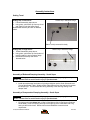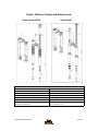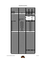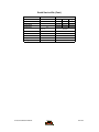
1
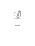
2004 SERVICE MANUAL
South Super
South Elite
South Comp
28209 Avenue Stanford, Valencia, California 91355
661 257-4411 | fax 661 294-4179 |
www.answerproducts.com
Table of Contents
Description
Page
Introduction
3
Glossary of Terms
4
Disassembly Instructions
6
Assembly Instructions
7
Troubleshooting Chart
9
South Schematic and Torque Specifications
10
South Service Kit Chart
11
Contact Information
Answer Products Customer Service Department
28209 Ave. Stanford
Valencia, CA 91355
Toll Free: (800) 423-0273
Direct: (661) 257-4411
FAX:
(661) 775-1798
E-mail: [email protected]
[email protected]
Web site: www.answerproducts.com
04 SOUTH SERVICE MANUAL
Page 2
REV NC
INTRODUCTION
This manual is intended to guide the user through basic service of Manitou South front forks.
Service is supported by the identification of common parts and assemblies that have been
assembled into Service Kits. The purpose of this manual will be to describe conditions that may
drive the need for service and to provide installation instructions for the kits.
Due to the time-consuming nature suspension fork service, at this time our primary focus is to
offer service kits that minimize the amount of downtime and labor involved.
Important information is highlighted in this manual by the following notations:
WARNING
Failure to follow WARNING instructions could result in severe injury or death to the
person inspecting or repairing the suspension fork or the user.
CAUTION
A CAUTION a caution indicates special precautions that must be taken to avoid damage to
the product.
NOTE
A NOTE provides key information to make procedures easier or clearer
GENERAL WARNING: Suspension forks by design can contain preloaded springs, gases
and fluids under extreme pressure and warnings contained in this manual must be
observed to reduce the possibility of injury or possible death. Following these
instructions can help you reduce the risk of being injured. Any questions in regards to the
information in this manual should be directed to Answer Products Customer Service at
(661) 257-4411.
WARNING: Suspension forks uses preloaded spring(s) to provide compression spring
resistance. This system must be relieved of preload prior to servicing. Failure to relieve
air pressure could result in injury or possible death.
CAUTION: Suspension forks use precision machined aluminum and other soft alloy components.
Using correct tools for assembly is essential to prevent damage.
04 SOUTH SERVICE MANUAL
Page 3
REV NC
GLOSSARY OF TERMS
Arch – A support that connects the two outer lower legs of the casting so as to keep them moving
in unison.
Boss – The word used to describe an outer casting that has brake posts for V-brakes or
cantilever brakes.
Bottom Out Bumper – A rubber or elastomer device that absorbs the shock that occurs when a
suspension is compression to its limit.
Bushings – A cylindrical sleeve between a fork stanchion tube (inner leg) and a fork outer
casting (slider), which facilitates the sliding movement between these two parts.
Coil Spring – A coiled piece of metal that acts as a spring to help suspend a fork.
Compression – The phase of the suspension operation in which the wheel travels up, or travels
closer to the frame. The suspension forks reaction to a bump in the trail.
Convertible Travel – A system used to alter the travel of a suspension fork. It requires moving a
travel clip on the compression rod to a different position. This operation is accomplished by
disassembling the fork and physically moving the travel clip on the compression rod.
Crown Steerer Assembly – the stanchion legs (inner legs), the fork crown, and the steer tube
pressed together as one assembly. This assembly is then finished by adding all of the fork
internals and then outer casting (slider).
Drop Out – The end of an outer casting (slider) where the wheel attaches.
Dust Boot – Usually a piece of rubber in the shape of a cylinder with baffles to allow it to
compress as the fork compresses through its travel. Its function is to help keep dirt and water
from getting into the inner legs of the fork.
Fork Crown – The component that joins the stanchion tubes (inner legs) to the steer tube of the
fork.
MCU – (Micro-Cellular Urethane) Special urethane that is filled with tiny air cells that act like
springs when the elastomer is compressed.
No Boss - The word used to describe an outer casting that has no brake posts for V-brakes or
cantilever brakes. This casting is to be used for disk brakes only.
O-Ring – A soft, flexible neoprene or Buna rubber ring with a round cross-section, which is used
for sealing and retention.
Outer Casting – (see Slider)
Preload – A condition of compressing a spring or elastomer before the operating loads are put on
the suspension, so that it provides a stiffer spring rate.
Rebound – The phase of the suspension operation in which the wheel returns to its original
position on the ground after compression.
04 SOUTH SERVICE MANUAL
Page 4
REV NC
Reverse Arch Technology – Also known as RA. It is a system that is designed to move the arch
of a fork to the backside of a fork, rather than the conventional front position. It was designed to
provide greater rotational torque strength to an outer casting (slider), without adding additional
weight to the fork.
SAG – The amount a suspension fork compresses at rest with a normal load (rider’s weight).
Seal – A part, usually neoprene rubber or Buna, that keeps contaminants out and/or working
fluids in.
Spring Rate – The rate at which the resistance of a spring increases as it is compressed.
Slider/Outer Casting – The tube (outer casting leg) of the suspension fork that remains fixed to
the wheel. It slides up and down on the stanchion leg (inner leg).
Stanchion Legs – The suspension tube (inner leg) fixed to the fork crown. It remains stationary
during the operation of the suspension.
Steer Tube – The long cylindrical tube that extends from the top of the fork crown. Its function is
to be inserted into the bicycle head tube and attach the suspension to the bicycle frame.
Top Out Bumper – A rubber, coil spring, or elastomer device that absorbs the shock that occurs
when the load is taken off a suspension so that it is allowed to rebound to its limits
Travel – The amount that a wheel moves between the most compressed and the most extended
states of the suspension
Wiper Seal – A rubber material that is used as a seal to keep dirt and water out of the outer
casting legs. It is not designed to keep air pressure or extreme oil pressure in. Manitou has the
new Evil Genius wiper seals.
04 SOUTH SERVICE MANUAL
Page 5
REV NC
2004 South Forks Disassembly and Rebuild Instructions
Disassembly Instructions
Removal of Outer Casting
1. From the left leg dropout (Left when sitting on the bike), use a 4mm hex wrench to
remove the compression rod screw.
2. South Comp and Elite: From the right leg dropout, use a 6mm hex wrench to turn the
compression rod clockwise until it can be pushed into the casting. If you cannot
unscrew the compression rod see step 5 below.
3. South Super: From the right leg dropout, use a 8mm hex wrench to turn the compression
rod clockwise until it can be pushed into the casting. If you cannot
4. Remove crown/steer/inner leg assembly from the outer leg casting.
Bushing Removal & Installation
Please refer to section on Bushing Removal & Installation.
Removal of Spring and Compression Rod Assembly
WARNING This fork uses a preloaded coil spring provide spring resistance. The spring
must be relieved of its preload prior to servicing. Failure to do so could result in injury or
possible death.
1. Turn spring preload adjuster knob counter clockwise until it stops. Remove 2mm hex
screw on spring preload adjuster knob and remove knob on the top left side of the fork.
2. Remove preload adjuster using 18mm socket.
3. Compress fork and remove the spring preload, MCU, and spring assy.
4. South Comp and Elite: Remove top leg cap on right hand side using 27mm socket. If you
could not remove the right side compression rod externally, reach down inside the inner
leg with a 6mm hex, the top of the compression rod has a recessed 6mm hex that a hex
wrench will fit into. The comp rod can be unscrewed counterclockwise at this point.
Remove crown/steer/inner leg assembly from the outer leg casting.
5. Remove rubber bumper and clip on compression rods.
6. Turn crown/steer upside down to allow the comp rods to fall out of the inner legs.
Removal of Compression Damping Assembly - South Super
1. Remove the 2mm fixing screw on top of the damper knob on top right side of the fork.
2. Remove 2 balls and springs from inside the top cap.
3. Unscrew the compression damping assembly using a 24mm socket. Pour old oil out of
the top of the fork, then compress fork upside down over oil drain pan 3-5 times to get oil
out from under rebound piston and discard appropriately.
Removal of Rebound Damping Assembly - South Super
1. Unscrew Damper end cap from the bottom of the right leg and then pull out the rebound
damper.
04 SOUTH SERVICE MANUAL
Page 6
REV NC
Assembly Instructions
Setting Travel
Thicker Clip in slot below flange
Setting fork in short travel:
1. Follow Disassembly steps above.
2. Using pliers, pull thicker clip from top of rod
and install it in slot just below flange.
Reassemble assembly and fork as directed
below.
Bottom out clip removed for clarity
Setting fork in longer travel:
1. Follow Disassembly steps above.
2. Using pliers, pull thicker clip from bottom of
rod and install it in slot just above flange.
3. Reassemble assembly and fork as
directed below.
Thicker Clip in slot above flange
Assembly of Rebound Damping Assembly - South Super
WARNING All leg caps for Damper and Spring systems must be properly tightened prior
to use. Failure to do so could result in injury or possible death.
1. Install rebound damper into bottom of right leg and tighten per the South Schematic and
Torque Specification Table. Slide the black rubber bottomout up the shaft until it contacts
the damper cap. This will assist later during assembly of the outer leg casting to the
damper shaft.
Assembly of Compression Damping Assembly - South Super
WARNING All top caps for Damper and Spring systems must be properly tightened prior
to use. Failure to do so could result in injury or possible death.
1. Fill right leg with 110-120mm (4.3 – 4.7in.) of 5wt Motorex fork oil (Ref Answer Products
PN 85-0023). Cover the opening at the top of the right leg of the crown/steer with a rag
and cycle the fork six times. Recheck oil level and add/drain to meet the level
requirement.
04 SOUTH SERVICE MANUAL
Page 7
REV NC
2. Put a little bit of Prep M grease (Ref Answer Products PN 85-0031) on the urethane or
brown rubber o-ring found on the lower piston of the Lock out assembly.
3. Twist the Hex shaped aluminum shaft that sticks up from the top cap counter clockwise
until it stops (the system is completely open to oil flow at this point).
4. Using a motion like screwing in a screw. Twist the assy. and apply a little pressure to
insert the piston part of the mechanism past the threads at the top of the inner leg. Then
push the assy. into the leg until the threads on the cap intersect the threads inside the
inner leg, screw the cap. Tighten per the South Schematic and Torque Specification
Table.
5. Once the cap is tightened, twist the Hex shaped shaft clockwise until it stops (this is the
locked out position). Insert the springs into opposite holes in the top cap and then place
the ball bearings on top of the springs (place a little dab of grease on spring to hold ball
bearing in place).
6. Place the adjuster knob onto the hex shaped aluminum shaft and seat it onto the top cap
and ball bearing. Position the adjuster cap so that the lever part of the cap is at the
farthest point to the back of the crown.
7. Insert 2mm fixing screw and tighten to secure the knob. Twist the knob counter clockwise
to activate the fork suspension. Compress the fork several times to circulate the oil
through the system and then activate the Lock out system by moving the lever clockwise
to its stopping point at the back of the crown. The fork should have approximately 5 mm
of progressive travel before it locks out.
Note: This system is a combination of adjustable compression damping that becomes a lock
out. It is fully active when the lever is facing all the way forward (counter clockwise) and
locked out when the lever is facing all the way towards the back of the crown (clockwise).
Installation of Spring, Compression Rod Assembly, and Outer Leg Casting
WARNING All top caps for Damper and Spring systems must be properly tightened prior
to use. Failure to do so could result in injury or possible death.
WARNING When installing the outer Leg Casting to the Crown Steer Assy, Compression
Rod bolts and Damper Shafts must be properly tightened prior to use. Failure to do so
could result in injury or possible death.
Note: Non dampened South forks (Comp and Elite) use two compression rods, one in each leg.
Dampened south forks (Super) only use a compression rod in the left side.
1. Drop the compression rod(s) into the crown/steer assy. Make sure that the comp rod that
accepts the 4mm screw is installed in the left leg.
2. Slide on the rubber bottomout bumper and clip onto the compression rod(s)
3. Remove rubber fork boots from the casting and slide them onto the inner legs of the
crown/steer assy.
4. Lightly grease the bushings on the inside of the outer leg casting and on the lower portion
of the inner legs below the boots using a thick grease such as Motorex Bike Grease
2000.
5. Grease spring heavily with Motorex Bike Grease 2000. Install the spring preload, MCU,
and spring assy into the crown/steer assy.
6. Tighten preload adjuster using 18mm socket and tighten per the South Schematic and
Torque Specification Table.
7. Insert 2mm hex screw into spring preload adjuster knob and install knob on the top left
side of the fork.
8. Press inner leg assembly into outer leg casting until comp rod contacts casting.
9. From the left leg dropout, use a 4mm hex wrench to install the compression rod screw
and tighten per the South Schematic and Torque Specification Table.
04 SOUTH SERVICE MANUAL
Page 8
REV NC
10. South Comp and Elite: From the right leg dropout, use a 6mm hex wrench to turn the
compression rod counterclockwise until it screws into the casting. You may have to
apply pressure from the top of the comp rod using a long 6mm hex to start screwing it in
and tighten per the South Schematic and Torque Specification Table.
11. South Super: From the right leg dropout, use a 8mm hex wrench to turn the compression
damper counterclockwise until it screws into the casting and tighten per the South
Schematic and Torque Specification Table.
12. Slide fork boots down and snap over dust seal flange.
13. Lubricate the inner legs through the Microlube ports using Prep-M grease.
04 SOUTH SERVICE MANUAL
Page 9
REV NC
Troubleshooting Chart
Symptom
Oil leaks from
Wiper Seals
Oil leaks from
bottom of
Casting
Lack of Travel
Fork Top out
Fork Bottom
out
Play in Fork
Cause
Solution
Seal not seated properly
Remove Casting from Inner Legs, reinstall
or replace seals
Nicks or scratches on
inner legs
Replace Crown/Steerer/Inner Leg
Assembly
Wear
Remove Casting from Inner Legs, reinstall
or replace seals
Rebound damper shaft
leaks
Replace Rebound Damping assembly
Rebound damper shaft Oring damaged
Replace O-ring on threaded end of
Rebound Damping assembly
Tight Bushings
Hydraulic lock out
Replace outer leg
Replace Rebound Damping assembly
Damper oil volume
Check oil level, Replace Rebound
Damping assembly if needed
Fork alignment
Visually inspect fork, call Answer
Products Customer Service
Loss of Rebound
Damping
Replace Rebound Damping assembly
Top out spring damaged
Inspect and replace Top out spring if
needed.
Damping oil volume not
correct
Check oil level, Replace Rebound
Damping assembly if needed
Too much SAG
Refer to SAG Set up in Tuning section of
Owners Manual
Bottom out Bumper
damaged
Inspect and replace Bottom out Bumper if
needed
Damping oil volume not
correct
Check oil level, Replace Rebound
Damping assembly if needed
Loose bushings
Replace outer leg
Loose Compression Rod
bolt
Tighten bolt to specified torque
Loose Rebound damping
shaft
Tighten Shaft to specified torque
Loose press fit tolerances
Call Answer Products Customer Service
04 SOUTH SERVICE MANUAL
Page 10
Service
Manual
Page
REV NC
South : Fastener Torque and Setup Levels
South Comp & Elite
South Super
Model: South
Description
Torque Value
Torque – Brake Post
90–110inlbs (10.2-12.4nm)
Leg Caps
25–35inlbs (2.8-4.0nm)
Torque - Comp Rod Screw
10-30inlbs (1.1-3.4nm)
Torque - Damper Screw (South Super)
10-30inlbs (1.1-3.4nm)
Adjuster caps:
Torque
Damping Oil - South Super
04 SOUTH SERVICE MANUAL
35-50inlbs (4.0-5.7nm)
110 – 120mm (4.3 – 4.7”)
Page 11
REV NC
South Service Kits
South
Model
Comp
Elite
Super
Code
D-410
D-420
D-430
60 or 75
60 or 75
60 or 75
Travel (mm)
Comp Damp
A
85-5318
Rbnd Damp
B
85-5319
Pre Load Adj/Top Cap
C
Crn/Str/Leg
D
***Steel S/T (26")
85-4810
85-5325
85-5335
85-5329
85-5328
***Steel S/T (700C)
***Steel Threaded (26)
***Steel Threaded
(700c)
Outer Leg Assy
E
STD
Black (26")
85-5330
STD
Black (700c)
85-5331
STD
Silver (26")
85-5332
STD
Silver (700c)
85-5333
STD
Red (26")
85-5334
STD
Red (700C)
85-4458
STD
Cobalt
85-5337
STD
Orange
85-5338
STD
Yellow
85-5339
STD
Candy Chrome
85-5340
STD
Candy Red
85-5341
STD
Candy Blue
85-5342
No Boss
Black (26")
85-5343
No Boss
Black (700c)
85-5344
No Boss
Silver (26")
85-5345
No Boss
Silver (700c)
85-5346
No Boss
Red (26")
85-5347
No Boss
Red (700C)
85-5348
No Boss
White
85-5349
No Boss
Cobalt
85-5350
No Boss
Orange
85-5351
No Boss
Yellow
85-5352
No Boss
Candy Chrome
85-5353
No Boss
Candy Red
85-5354
No Boss
Candy Blue
85-5355
F - Silver
85-5356
F - Black
85-5357
Sticker Kit
Ride Kits
04 SOUTH SERVICE MANUAL
G
***Soft
85-5358
***Medium
85-5359
***Firm
85-5360
Page 12
REV NC
South Service Kits (Cont.)
South
Model
Comp
Elite
Super
Code
D-410
D-420
D-430
60 or 75
60 or 75
60 or 75
Travel (mm)
Comp Rod/
H
60 or 75
85-5361
Knob Kit
I
85-5362
Boot Kit
J
85-5390
Seal Kit
K
85-5391
Bumper Kit
K
85-5363
O-Ring Kit
K
85-5555
04 SOUTH SERVICE MANUAL
Page 13
REV NC