1
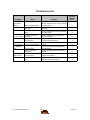
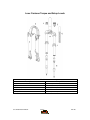
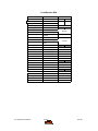
2004 SERVICE MANUAL
Luxe Super
Luxe Elite
28209 Avenue Stanford, Valencia, California 91355
661 257-4411 | fax 661 294-4179 |
www.answerproducts.com
Table of Contents
Description
Page
Introduction
3
Front Suspension Terminology
4
Disassembly Instructions
6
Assembly Instructions
6
Troubleshooting Chart
7
Luxe Schematic and Torque Specifications
8
Luxe Service Kit Chart
9
Contact Information
Answer Products Customer Service Department
28209 Ave. Stanford
Valencia, CA 91355
Toll Free: (800) 423-0273
Direct: (661) 257-4411
FAX:
(661) 775-1798
E-mail: [email protected]
[email protected]
Web site: www.answerproducts.com
04 LUXE SERVICE MANUAL
Page 2
REV NC
INTRODUCTION
This manual is intended to guide the user through basic service of Manitou Luxe front forks.
Service is supported by the identification of common parts and assemblies that have been
assembled into Service Kits. The purpose of this manual will be to describe conditions that may
drive the need for service and to provide installation instructions for the kits.
Due to the time-consuming nature suspension fork service, at this time our primary focus is to
offer service kits that minimize the amount of downtime and labor involved.
Important information is highlighted in this manual by the following notations:
WARNING
Failure to follow WARNING instructions could result in severe injury or death to the
person inspecting or repairing the suspension fork or the user.
CAUTION
A CAUTION a caution indicates special precautions that must be taken to avoid damage to
the product.
NOTE
A NOTE provides key information to make procedures easier or clearer
GENERAL WARNING: Suspension forks by design can contain preloaded springs, gases
and fluids under extreme pressure and warnings contained in this manual must be
observed to reduce the possibility of injury or possible death. Following these
instructions can help you reduce the risk of being injured. Any questions in regards to the
information in this manual should be directed to Answer Products Customer Service at
(661) 257-4411.
WARNING: Suspension forks uses preloaded spring(s) to provide compression spring
resistance. This system must be relieved of preload prior to servicing. Failure to relieve
air pressure could result in injury or possible death.
CAUTION: Suspension forks use precision machined aluminum and other soft alloy components.
Using correct tools for assembly is essential to prevent damage.
04 LUXE SERVICE MANUAL
Page 3
REV NC
GLOSSARY OF TERMS
Arch – A support that connects the two outer lower legs of the casting so as to keep them moving
in unison.
Boss – The word used to describe an outer casting that has brake posts for V-brakes or
cantilever brakes.
Bottom Out Bumper – A rubber or elastomer device that absorbs the shock that occurs when a
suspension is compression to its limit.
Bushings – A cylindrical sleeve between a fork stanchion tube (inner leg) and a fork outer
casting (slider), which facilitates the sliding movement between these two parts.
Coil Spring – A coiled piece of metal that acts as a spring to help suspend a fork.
Compression – The phase of the suspension operation in which the wheel travels up, or travels
closer to the frame. The suspension forks reaction to a bump in the trail.
Convertible Travel – A system used to alter the travel of a suspension fork. It requires moving a
travel clip on the compression rod to a different position. This operation is accomplished by
disassembling the fork and physically moving the travel clip on the compression rod.
Crown Steerer Assembly – the stanchion legs (inner legs), the fork crown, and the steer tube
pressed together as one assembly. This assembly is then finished by adding all of the fork
internals and then outer casting (slider).
Drop Out – The end of an outer casting (slider) where the wheel attaches.
Dust Boot – Usually a piece of rubber in the shape of a cylinder with baffles to allow it to
compress as the fork compresses through its travel. Its function is to help keep dirt and water
from getting into the inner legs of the fork.
Fork Crown – The component that joins the stanchion tubes (inner legs) to the steer tube of the
fork.
MCU – (Micro-Cellular Urethane) Special urethane that is filled with tiny air cells that act like
springs when the elastomer is compressed.
No Boss - The word used to describe an outer casting that has no brake posts for V-brakes or
cantilever brakes. This casting is to be used for disk brakes only.
O-Ring – A soft, flexible neoprene or Buna rubber ring with a round cross-section, which is used
for sealing and retention.
Outer Casting – (see Slider)
Preload – A condition of compressing a spring or elastomer before the operating loads are put on
the suspension, so that it provides a stiffer spring rate.
Rebound – The phase of the suspension operation in which the wheel returns to its original
position on the ground after compression.
04 LUXE SERVICE MANUAL
Page 4
REV NC
Reverse Arch Technology – Also known as RA. It is a system that is designed to move the arch
of a fork to the backside of a fork, rather than the conventional front position. It was designed to
provide greater rotational torque strength to an outer casting (slider), without adding additional
weight to the fork.
SAG – The amount a suspension fork compresses at rest with a normal load (rider’s weight).
Seal – A part, usually neoprene rubber or Buna, that keeps contaminants out and/or working
fluids in.
Spring Rate – The rate at which the resistance of a spring increases as it is compressed.
Slider/Outer Casting – The tube (outer casting leg) of the suspension fork that remains fixed to
the wheel. It slides up and down on the stanchion leg (inner leg).
Stanchion Legs – The suspension tube (inner leg) fixed to the fork crown. It remains stationary
during the operation of the suspension.
Steer Tube – The long cylindrical tube that extends from the top of the fork crown. Its function is
to be inserted into the bicycle head tube and attach the suspension to the bicycle frame.
Top Out Bumper – A rubber, coil spring, or elastomer device that absorbs the shock that occurs
when the load is taken off a suspension so that it is allowed to rebound to its limits
Travel – The amount that a wheel moves between the most compressed and the most extended
states of the suspension
Wiper Seal – A rubber material that is used as a seal to keep dirt and water out of the outer
casting legs. It is not designed to keep air pressure or extreme oil pressure in. Manitou has the
new Evil Genius wiper seals.
04 LUXE SERVICE MANUAL
Page 5
REV NC
2004 Luxe Forks Disassembly and Rebuild Instructions
Disassembly Instructions
WARNING This fork uses a preloaded coil spring provide spring resistance. The
spring must be relieved of its preload prior to servicing. Failure to do so could result
in injury or possible death.
1. Turn spring preload adjuster knob counter clockwise until it stops. Remove 2mm hex
screw on spring preload adjuster knob and remove knob on the top left side of the fork.
2. Remove preload adjuster using 18mm socket.
3. Remove top leg cap on right hand side using 24mm socket.
4. Compress fork and remove the spring preload, MCU, and spring assy.
5. Invert fork and tap on work bench to remove plastic spacer from inside of left inner leg.
6. Using a _ inch drive 4mm hex on an extension remove the comp rod screws from inside
the bottom of both inner legs.
7. Pull off outer leg from crown/steer assy.
8. To remove compression rods, remove the compression rod clips (slotted washer if installed)
and the black rubber bottom out bumper. Feed the compression rod up through the inner
leg.
9. Rubber fork boots can now be removed and replaced from the casting at this time if
necessary.
Assembly Instructions
1. Remove rubber fork boots from the casting and slide them onto the inner legs of the
crown/steer assy.
2. Lightly grease the bushings on the inside of the outer leg casting and on the lower portion
of the inner legs below the boots using a thick grease such as Motorex Bike Grease
2000.
3. Reinstall compression rods into the inner legs if necessary.
4. Reinstall the bottomout bumpers and clips.
5. Slide the outer leg onto the crown/steer assy, make sure the arch is facing to the rear.
6. Using a _ inch drive 4mm hex on an extension tighten the comp rod screws from inside
the bottom of both inner legs. Torque per Luxe Fastener Torque and Setup Levels
section.
WARNING When installing the outer Leg Casting to the Crown Steer Assy,
Compression rod bolts must be properly tightened prior to use. Failure to do so
could result in injury or possible death.
7.
8.
9.
10.
11.
12.
13.
Snap boots over dust seal of outer leg casting.
Install plastic spacer into left inner leg.
Grease spring heavily with Motorex Bike Grease 2000.
Extend fork and install the spring preload, MCU, and spring assy.
Tighten preload adjuster using 18mm socket.
Install preload adjuster knob using 2mm hex screw.
Install top leg cap on right hand side using 24mm socket
04 LUXE SERVICE MANUAL
Page 6
REV NC
TROUBLESHOOTING
Symptom
Grease leaks
from Wiper
Seals
Lack of Travel
Fork Top out
Fork Bottom
out
Play in Fork
Solution
Service
Manual
Page
Seal not seated properly
Remove Casting from Inner Legs, reinstall
or replace seals
6
Nicks or scratches on
inner legs
Replace Crown/Steerer/Inner Leg
Assembly
6
Wear
Remove Casting from Inner Legs, reinstall
or replace seals
6
Insufficient grease on
inner legs
Remove Casting from Inner Legs and
regrease bushings
6
Fork alignment
Visually inspect fork, call Answer
Products Customer Service
3
Top out spring damaged
Inspect and replace Top out spring if
needed.
6
Too much SAG
Refer to SAG Set up in Tuning section of
Owners Manual
Bottom out Bumper
damaged
Inspect and replace Bottom out Bumper if
needed
6
Loose bushings
Replace outer casting
6
Loose Compression Rod
bolt
Tighten bolt to specified torque
6
Cause
04 LUXE SERVICE MANUAL
Page 7
REV NC
Luxe: Fastener Torque and Setup Levels
Model: Luxe
Description
Torque Value
Torque – Brake Post
90–110inlbs (10.2-12.4nm)
Leg Caps
25–35inlbs (2.8-4.0nm)
Torque - Comp Rod Screw
10-30inlb (1.1-3.4nm)
Adjuster caps:
Torque
04 LUXE SERVICE MANUAL
35-50inlbs (4.0-5.7nm)
Page 8
REV NC
Luxe Service Kits
Luxe
Model
Code
Travel (mm)
Pre Load Adj/Top Cap
C
Crn/Str/Leg
Elite
T-410
Super
T-420
60
60
85-4800
D
***Steel S/T (26")
***Steel S/T (700C)
***Blk AL S/T(26")
STD/SM
85-5301
85-5303
***Blk AL S/T(700C)
85-5303
***Steel Threaded (26)
***Steel Threaded
(700c)
85-5307
Outer Leg Assy
E
STD
Black (26")
85-5309
STD
Black (700c)
85-5310
STD
Silver (26")
85-5311
STD
Silver (700c)
85-5312
F - Silver
85-5313
F - Black
85-5314
Sticker Kit
Ride Kits
G
***Soft
85-5030
***Medium
85-5031
***Firm
Comp Rod/
85-5032
H
60
85-5315
Knob Kit
I
85-5210
Boot Kit
J
85-5211
Seal Kit
K
85-5316
Bumper Kit
K
85-5317
04 LUXE SERVICE MANUAL
Page 9
REV NC