1
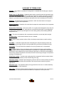
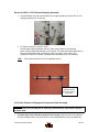
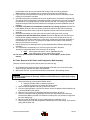
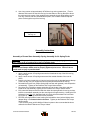
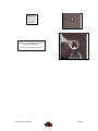
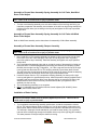
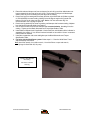
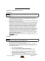
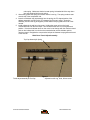
2004 SERVICE MANUAL
Black Super
Black Elite
Black Comp
28209 Avenue Stanford, Valencia, California 91355
661 257-4411 | fax 661 294-4179 |
www.answerproducts.com
Table of Contents
Description
Page
Introduction
3
Glossary of Terms
4
Disassembly Instructions
8
Assembly Instructions
12
Travel Adjust Systems: Wind Down
16
Bushing Removal and Installation Instructions
19
Troubleshooting Chart
23
Black Comp & Elite Schematic and Torque Specifications
25
Black Super Schematic and Torque Specifications
26
Black Platinum Schematic and Torque Specifications
27
Black Service Kit Chart
28
Contact Information
Answer Products Customer Service Department
28209 Ave. Stanford
Valencia, CA 91355
Toll Free: (800) 423-0273
Direct: (661) 257-4411
FAX:
(661) 775-1798
E-mail: [email protected]
[email protected]
Web site: www.answerproducts.com
04 BLACK SERVICE MANUAL
Page 2
REV NC
INTRODUCTION
This manual is intended to guide the user through basic service of Manitou Black front forks.
Service is supported by the identification of common parts and assemblies that have been
assembled into Service Kits. The purpose of this manual will be to describe conditions that may
drive the need for service and to provide installation instructions for the kits.
Due to the time-consuming nature suspension fork service, at this time our primary focus is to
offer service kits that minimize the amount of downtime and labor involved.
Important information is highlighted in this manual by the following notations:
WARNING
Failure to follow WARNING instructions could result in severe injury or death to the
person inspecting or repairing the suspension fork or the user.
CAUTION
A CAUTION a caution indicates special precautions that must be taken to avoid damage to
the product.
NOTE
A NOTE provides key information to make procedures easier or clearer
GENERAL WARNING: Suspension forks by design contain gases and fluids under extreme
pressure and warnings contained in this manual must be observed to reduce the
possibility of injury or possible death. Following these instructions can help you reduce
the risk of being injured. Any questions in regards to the information in this manual
should be directed to Answer Products Customer Service at (661) 257-4411.
WARNING: The Black uses compressed air to provide fluid pressure in the damping
system and spring resistance in Air models. BOTH systems must be relieved of pressure
prior to servicing these systems. Failure to relieve air pressure could result in injury or
possible death.
CAUTION: The Black suspension fork uses precision machined aluminum and other soft alloy
components. Using correct tools for assembly is essential to prevent damage.
04 BLACK SERVICE MANUAL
Page 3
REV NC
GLOSSARY OF TERMS
Air Cap – Top cap that threads into top of air/spring leg (this is the left leg of the fork as you are
seated on the seat). Forks may be controlled with an air/spring or a coil spring. The air cap
contains the Schrader Valve, which is used to control the spring rate or SAG of air forks.
Air Spring – A mechanism that is used to control the SAG of an air fork.
Arch – A support that connects the two outer lower legs of the casting so as to keep them moving
in unison.
Boss – The word used to describe an outer casting that has brake posts for V-brakes or
cantilever brakes.
Bottom Out Bumper – A rubber or elastomer device that absorbs the shock that occurs when a
suspension is compression to its limit.
Bushings – A cylindrical sleeve between a fork stanchion tube (inner leg) and a fork outer
casting (slider), which facilitates the sliding movement between these two parts.
Coil Spring – A coiled piece of metal that acts as a spring to help suspend a fork.
Compression – The phase of the suspension operation in which the wheel travels up, or travels
closer to the frame. The suspension forks reaction to a bump in the trail.
Compression Damping – Restriction of the rate that the suspension compresses under load.
Convertible Travel – A system used to alter the travel of a suspension fork. It requires moving a
travel clip on the compression rod to a different position. This operation is accomplished by
disassembling the fork and physically moving the travel clip on the compression rod.
Crown Steerer Assembly – the stanchion legs (inner legs), the fork crown, and the steer tube
pressed together as one assembly. This assembly is then finished by adding all of the fork
internals and then outer casting (slider).
Damping – A function that modifies the rate of suspension compression or rebound.
Detent – An indentation that causes a rotating adjuster to stop at fixed increments.
Drop Out – The end of an outer casting (slider) where the wheel attaches.
Dust Boot – Usually a piece of rubber in the shape of a cylinder with baffles to allow it to
compress as the fork compresses through its travel. Its function is to help keep dirt and water
from getting into the inner legs of the fork.
FFD – Fluid Flow Damping. A Manitou patented low cost oil damping system. The compression
damping is non-adjustable and the rebound damping may be non-adjustable or adjustable
damping.
04 BLACK SERVICE MANUAL
Page 4
REV NC
GLOSSARY OF TERMS (CONT.)
Fork Crown – The component that joins the stanchion tubes (inner legs) to the steer tube of the
fork.
Hydraulic Fork Oil – Oil used in suspension designs to provide damping. It has special
characteristics that determine how it reacts when exposed to compressed air, how it changes
viscosity when its temperature changes, and how it moves through valves.
Hydraulic Lock Out – a condition caused when the mixture of air and damping oil is out of
balance. It is caused when there is too little air space in a chamber, not allowing the fork to
compress through its travel.
Lock Out – a special function that restricts the compression of the fork from moving. It is
generally controlled by an external knob that is activated when a rider does not want the fork to
move, thus eliminating extra energy needed to overcome the bobbing forces of the fork.
MCU – (Micro-Cellular Urethane) Special urethane that is filled with tiny air cells that act like
springs when the elastomer is compressed.
Micro Lube – Lubrication system that is operated by injecting small quantities of grease directly
into ports that are inserted into outer casting legs. This enables the lubrication of the fork without
having to disassemble it.
No Boss - The word used to describe an outer casting that has no brake posts for V-brakes or
cantilever brakes. This casting is to be used for disk brakes only.
Oil Damping – A system that uses the resistance to oil flow through holes in a valve to provide a
means to alter the rate of suspension compression or rebound.
Oil Level – The level of damping oil needed for the optimal damping performance of a
suspension. It is measured as the air space distance between the top of the stanchion leg (inner
leg) and the height of the oil inside of the leg. The fork must be completely extended in order to
get an accurate measurement.
O-Ring – A soft, flexible neoprene or Buna rubber ring with a round cross-section, which is used
for sealing and retention.
Oil Weight – A description of the relative viscosity of oil, such as hydraulic oil. Oil with low weight
numbers (5wt or 7wt) flow through valves with less resistance than higher weight numbers (10or
15 wt).
Outer Casting – (see Slider)
Preload – A condition of compressing a spring or elastomer before the operating loads are put on
the suspension, so that it provides a stiffer spring rate.
Piston – In front suspension, the part of the damper that slides back and forth inside of the
damping leg that houses the valves. It can also refer to the air piston in the air/spring assembly
that slides back and forth compressing the air, thus causing a change in the spring rate of the
suspension.
04 BLACK SERVICE MANUAL
Page 5
REV NC
GLOSSARY OF TERMS (CONT.)
Porosity – The condition or property of having pores in a material that will allow gas or liquid to
pass through it.
Rapid Travel I, II, Wind Down – Systems that are used to control the travel of suspension forks.
Also known as RTI, RTII, and WD. RTI and RTII are used for the specific purposes of controlling
the travel in two conditions: climbing and descending. WD is an incremental travel adjustment
between to set limits and does not affect the spring rate of the fork as severely as RTI and RTII.
Rebound – The phase of the suspension operation in which the wheel returns to its original
position on the ground after compression.
Rebound Damping – Restriction of the rate that the suspension rebounds when the compression
load is relived.
Reverse Arch Technology – Also known as RA. It is a system that is designed to move the arch
of a fork to the backside of a fork, rather than the conventional front position. It was designed to
provide greater rotational torque strength to an outer casting (slider), without adding additional
weight to the fork.
SAG – The amount a suspension fork compresses at rest with a normal load (rider’s weight).
Schrader Valve – Valve used to introduce air into a chamber.
Seal – A part, usually neoprene rubber or Buna, that keeps contaminants out and/or working
fluids in.
Semi Bath – A lubrication system that uses a lubricating oil to keep the bushing surface and
stanchion legs (inner legs) as friction free as possible during movement of the stanchion legs.
Spring Rate – The rate at which the resistance of a spring increases as it is compressed.
SPV – (Stable Platform Valve) new damping system that allows the rider to set the pedaling
platform that he desires to pedal most efficiently in all situations. It is dependent on the pressure
that the SPV valve experiences from the movement of the wheel vs. the terrain and the platform
that is set by pressure introduced to other side of the SPV valve through changes of air pressure
working on the damping oil.
Slider/Outer Casting – The tube (outer casting leg) of the suspension fork that remains fixed to
the wheel. It slides up and down on the stanchion leg (inner leg).
Stanchion Clamps - (Double-Triple Clamps) the portions of the fork crown that clamp around the
stanchion legs above and below the head tube of the bicycle frame on specific long travel
applications.
Stanchion Legs – The suspension tube (inner leg) fixed to the fork crown. It remains stationary
during the operation of the suspension.
Steer Tube – The long cylindrical tube that extends from the top of the fork crown. Its function is
to be inserted into the bicycle head tube and attach the suspension to the bicycle frame.
04 BLACK SERVICE MANUAL
Page 6
REV NC
GLOSSARY OF TERMS (CONT.)
Thru Axle – A device used for mounting a thru axle hub to special outer legs that are not made
for standard quick release hubs. Manitou’s Thru Axle system is a special patented system
utilizing a hex shaped end that increases the stiffness of the fork and reduces slippage in the joint
between the axle clamps and the axle.
Top Out Bumper – A rubber, coil spring, or elastomer device that absorbs the shock that occurs
when the load is taken off a suspension so that it is allowed to rebound to its limits
TPC – (Twin Piston Chamber) a patented damping system that has independent pistons for
rebound and compression. The system utilizes a mixture of air and oil in the damping leg of the
fork to enhance the damping performance.
TPC+ - A variation of TPC that has added a floating piston to the compression damper to
enhance the performance of the compression damping under the load of bigger hits.
Travel – The amount that a wheel moves between the most compressed and the most extended
states of the suspension
Viscosity – A description of how a liquid flows. Liquids with higher viscosity are thicker flow less
easily or quickly than liquids with low viscosity. This has an affect on the damping speeds of
rebound and compression.
Volume Control – A new system designed to work with SPV as a control of the compression
ramp up rate of the fork. It has a range of adjustments from linear to very progressive.
Wiper Seal – A rubber material that is used as a seal to keep dirt and water out of the outer
casting legs. It is not designed to keep air pressure or extreme oil pressure in. Manitou has the
new Evil Genius wiper seals.
04 BLACK SERVICE MANUAL
Page 7
REV NC
2004 Black Forks Disassembly and Rebuild Instructions
Disassembly Instructions
Removal of Outer Casting
WARNING This fork uses a preloaded coil spring provide spring resistance. The spring
must be relieved of its preload prior to servicing. Failure to do so could result in injury or
possible death.
1. On forks with Wind Down, be sure to set travel to its longest setting. For Wind Down, rotate
adjuster on top left of fork crown counterclockwise until it stops. This will relieve spring
tension on the fork. More complete instructions for servicing Travel Adjust systems may be
found in the “Travel Adjust “section.
2. Turn the fork upside down and remove the fixing screw that attaches the Rebound Adjuster
Knob (Blue). Set both knob and screw aside.
USE: 2mm Allen wrench to unscrew fixing screws.
3. Remove the 11mm Compression Rod bolt from the bottom of the left leg (From the rider's
perspective).
USE: 11mm socket, nut driver, or open-end wrench.
4. Insert 8mm Allen wrench into the end of the Rebound Damper Shaft on the bottom of the
right leg. Turn the wrench in a Clock Wise direction in order to loosen the damper shaft in
the casting (See Figure below). You are turning the Damper Shaft in a way that causes it to
disappear into the casting leg.
USE: 8mm Allen wrench
6. Working with the “Semi Bath” lubrication system:
A. Position the bottom of the fork legs over a drain pan that is on the ground. Pull the
casting downward towards the pan, allowing the Semi Bath oil in the casting to drip
into the pan. Pull the casting completely off of the inner legs and wipe any excess oil
off of inner legs and inside of casting.
USE: Drainage pan and extra rags
Bushing Removal & Installation
Please refer to section on Bushing Removal & Installation.
04 BLACK SERVICE MANUAL
Page 8
REV NC
Removal of TPC Compression Damping Assembly
(Assembly is on the top left side of crown, from riders perspective)
1. For forks with Adjustable compression damping/Lock out: twist the knob all the way
counter clockwise to reduce the amount of compression damping on the system.
2. Unscrew the 2mm Allen screw that holds the adjuster knob to the damping assembly.
3. Remove the adjuster knob and unscrew the compression assembly from the crown. It may
be necessary to twist the assembly like you would be unscrewing a screw and gently pull
upward to free the assembly from the crown.
(Note: there will be a small amount of oil that comes out of the inner leg, when the
assembly is pulled from the crown)
Use: 2mm Allen wrench, 20mm socket
1. For forks with Non-Adjustable compression damping: unscrew the damping assembly top
cap from the crown. It may be necessary to twist the assembly like you would be unscrewing
a screw and gently pull upward to free the assembly from the crown.
(Note: there will be a small amount of oil that comes out of the inner leg, when the
assembly is pulled from the crown)
Use: 26mm socket
Removal of SPV Compression Damping Assembly
WARNING This fork uses compressed air as part of the SPV damping system and must be
relieved of pressure prior to servicing. Failure to relieve air pressure could result in injury
or possible death.
1. Remove Schrader valve dust cap from Red Hex Shaped Top Cap on the top right of the
crown. Release all air pressure from the Schrader valve.
2. Remove SPV Volume Control Cap (Red Hex Shaped Top Cap) from top right of the crown
with a 24mm Socket. Turn fork upside down over drainage pan to empty Damping oil from
the inner leg. Stroke the Damper shaft on the bottom of the inner leg 3-5 times to purge the
leg of oil that is caught below the oil piston.
USE:
24mm Socket, Valve core removal tool or small object that
can be used to depress valve stem
04 BLACK SERVICE MANUAL
Page 9
REV NC
Removal of SPV or TPC Rebound Damping Assembly
1. Unscrew Damper end cap from the bottom of the right leg and then pull the SPV or TPC
damping assembly out of inner leg.
2. To check the function of the SPV valve:
Visually inspect the gap between the SPV valve and the bottom of the damping
piston. It should have approximately 1mm of space. The valve should also spring back to
its open rested position after compressing it with your fingers. If the valve is not
responsive or all the time closed, it is bad and the assembly needs to be replaced.
USE:
24mm Open-end wrench or 8-10” Adjustable wrench
Check for 1mm gap
between the blue
SPV valve and the
black piston
Coil Forks: Removal of Spring and Compression Rod Assembly
WARNING This fork uses a preloaded coil spring provide spring resistance. The spring
must be relieved of its preload prior to servicing. Failure to do so could result in injury or
possible death.
1. For Black Super forks (Air/spring systems as the spring): Remove all of the air pressure
from the Schrader valve on top of the crown on the left side (Black top cap), by depressing
04 BLACK SERVICE MANUAL
Page 10
REV NC
2.
3.
4.
5.
6.
7.
8.
9.
10.
the Schrader valve. Be sure to hold fork with the top of the crown facing upwards.
(Note: When the air is released, this is a mixture of the oil and air inside the leg).
If you have not removed the Outer casting, refer to the above section on Removal of Outer
Casting, then proceed to next step.
Unscrew the end cap on the bottom of the inner leg and remove compression rod assembly.
This will consist of a compression rod, bottom and top out bumpers, the end cap, and should
be followed by a coil spring and then another rod (air push rod). This spring is the one that
would be changed if the fork’s SAG needed to be changed beyond the capabilities of the air
pressure.
For Black Forks with Pre-Load adjuster assemblies (coil spring systems): twist the PreLoad adjuster knob all of the way counter clockwise to reduce the pre-load on the spring.
Unscrew the 2mm Allen screw on top of the adjuster knob and remove the knob from the
assembly.
Unscrew the assembly from the crown and then pull the spring out of the inner leg.
For Black forks with the Wind Down system: Remove the adjuster knob from the top of
the Wind Down adjuster assembly on the top of the crown on the left side of the fork, by
unscrewing the 2mm Allen head screw. Use a 20mm socket and unscrew the remainder of
the assembly from the crown. The spring will be attached to the bottom of the assembly,
when you pull it form the inner leg.
Pull the spring from the assembly and it can be substituted with a different rated spring if
necessary.
The compression rod assembly on a Coil fork may be removed in the same
procedure as described above in the removal of an air spring.
a. USE: 24mm Open-end wrench or 8-10” Adjustable wrench,
2mm Allen wrench, 24mm socket, 20mm socket
For more specific details on Wind Down, refer to “Travel Adjust” section of this
manual.
Air Forks: Removal of Air Piston and Compression Rod Assembly
There are now two ways to remove the air piston from the inner leg.
1. An Air Piston Removal tool has been developed that will enable you to remove the piston
without having to take the fork apart. (P/N: 85-8062).
2. Without this new tool, you will need to follow the procedures in the following section.
WARNING This fork uses compressed air to provide spring resistance and must be
relieved of pressure prior to servicing. Failure to relieve air pressure could result in injury
or possible death.
1. Remove air dust cap covering the Schrader valves.
a. Depress Schrader valve to release air pressure.
b. Remove air cap on top of Left leg with 20mm socket.
2. Remove rebound adjuster knob using a 2mm hex wrench.
3. From the right leg dropout, use 8mm hex wrench to turn the damper shaft clockwise until
it can be pushed into the casting.
4. Remove 11mm hex bolt (Compression Rod bolt) from bottom of Left leg.
5. Remove crown/steer/inner leg assembly from the outer leg casting over a drain pan,
because Semi Bath oil will leak out of bottom of casting once you pull the inner legs from
the outer casting legs.
6. Be sure to drain all Semi Bath oil out of casting before re-assembly of fork.
7. Remove left leg end cap and compression rod assembly from inner left leg. Then remove
spring and Air piston rod.
04 BLACK SERVICE MANUAL
Page 11
REV NC
8. Use a long narrow rod approximately 18”/458mm long and no greater than _”/7mm in
diameter and insert it into the left inner leg from the bottom of the leg. Be sure to direct
the rod through the center of the negative spring assembly that is about halfway up the
inner leg. Once the rod has contacted the air piston, use a rubber mallet and tap the
piston out through the top of the inner leg.
Tapping Piston out
with long rod
Assembly Instructions
Assembly of Crown Steer Assembly: Spring Assembly for Air Spring Forks
WARNING All leg caps for Damper and Spring systems must be properly tightened prior to
use. Failure to do so could result in injury or possible death.
WARNING When installing the outer Leg Casting to the Crown Steer Assy, Compression
Rod bolts and Damper Shafts must be properly tightened prior to use. Failure to do so
could result in injury or possible death.
1. Apply a small amount of Prep M grease onto the threads at the top of the left inner leg
with your finger.
2. Apply a small amount of Prep M grease around the outside diameter of the new air
piston.
3. Insert the air piston (metal side up) into the inner leg through the threaded area at the top
of the inner leg. Use your fingers to push the piston past the threads into the leg.
4. Re-install the air push rod, positive spring (that has been well greased), and compression
rod assembly. Tighten per the Fastener and Torque Values section.
5. Pour about 3cc of a 40wt or greater automotive oil into the top of the piston and then
install the air cap assembly. Tighten per the Fastener and Torque Values section..
6. Fully extend the damper shaft and slide the rubber bumper against the inner leg end cap.
Insert the crown/steer assembly into the outer legs to the upper bushing. Holding the fork
horizontal, inject 16cc of 5-40wt Semi bath oil into the hole at the bottom of each outer
leg (Figure 2). A syringe works well for this procedure.
7. Push the outer legs past the lower bushing and reinstall the 4mm bolt and tighten 8mm
damper fitting in a counterclockwise direction. Tighten per the Fastener and Torque
Values section.
***Use a shock pump (p/n 85-4069) to fill the air system to the recommended levels as
outlined in the Black Fastener and Torque Values.
04 BLACK SERVICE MANUAL
Page 12
REV NC
Air Piston is
inserted into
inner leg with
metal side
facing up
Make sure to apply a thin layer of
grease to inner threads and outside of
piston before installation.
Pour 3 cc of oil into top of piston
04 BLACK SERVICE MANUAL
Page 13
REV NC
Assembly of Crown Steer Assembly: Spring Assembly for Coil Forks, Non-Wind
Down Travel Adjust
WARNING All leg caps for Damper and Spring systems must be properly tightened prior to
use. Failure to do so could result in injury or possible death.
1. Turn the crown/steer/leg assembly over so that the bottoms of the inner legs are facing you.
Install the compression rod assembly into the bottom of the left inner leg (the leg that was the
left side of the fork when you are sitting on the bicycle) and tighten the end cap to specified
torque value.
Assembly of Crown Steer Assembly: Spring Assembly for Coil Forks with Wind
Down Travel Adjust
Refer to Wind Down assembly service instructions for reassembly of Wind Down assembly.
Assembly of Crown Steer Assembly, Damper Assembly
WARNING All leg caps for Damper and Spring systems must be properly tightened prior to
use. Failure to do so could result in injury or possible death.
1. Now, install SPV or TPC damping assembly into bottom of other inner leg. Be sure to check
the function of the SPV valve and apply a thin layer of Prep M grease onto o-ring that is
around the piston at top of assembly. Install the assembly and tighten end cap to specified
torque value.
2. Turn Crown/steer/leg assembly right side up, so that the crown of the assembly is facing you.
Extend the SPV or TPC damping assembly all the way out and then pour damping oil (P/N:
85-0023) into the right inner leg. Fill leg about _ full. Take a rag and cover the top of the right
inner leg and then stroke the SPV or TPC damping assembly up and down about 5 times.
This will insure that oil gets below the piston and not create an air space. Extend the damping
assembly all the way out and then fill the inner leg to the specified oil level.
3. Insert the Volume control or TPC compression damping assembly into the top of the right
inner leg and tighten it to specified torque value. Install compression damping adjuster knob if
necessary and secure with 2mm Allen screw. Be sure that you unscrew the red 16mm Hex
shaped Volume control nut all of the way counterclockwise after you tighten the entire
assembly into the inner leg.
4. The crown/steer/leg assembly is now complete.
5. Use: 8-10” adjustable wrench, Manitou Volume Control Adjuster (P/N: 85-3007), 24mm
socket, 20mm socket, metric ruler.
Installation of Outer Casting
WARNING When installing the outer Leg Casting to the Crown Steer Assy, Compression
Rod bolts and Damper Shafts must be properly tightened prior to use. Failure to do so
could result in injury or possible death.
1. Turn completed crown/steer/leg assembly upside down, so that the compression rod and
SPV or TPC rebound damper shaft are facing you. You will see a bottom out bumper on the
damper shaft; slide this bumper down towards the end cap that is threaded into the inner leg.
This will help in keeping the shaft extended as you install the outer casting. You could also
insert air into the damper leg through the Schrader valve on top of the right leg (SPV models).
This extra pressure will help to keep the shaft from moving.
04 BLACK SERVICE MANUAL
Page 14
PN XXXXXX REV NC
2. Extend the rebound damper out from end cap as far as it will go and then slide bottom out
bumper towards the end cap as far as it will go. The bumper will help to hold the damper
shaft in place as you are inserting the inner legs into the casting.
3. Press inner legs into casting about half way and then inject Semi Bath oil (5/40wt. synthetic
oil, P/N: 85-0022) into outer casting, holding fork at 45 degree angle to the ground with
bottom of fork in the air (drop outs up). Inject 16cc’s of oil into each outer leg. It is
recommended to use a syringe to inject oil.
4. Press inner leg assembly into outer leg casting until damper shaft contacts casting. Adjuster
hex shaft should protrude slightly from casting.
5. Use an 8mm hex wrench to turn the damper shaft counterclockwise, threading it into the
casting. Tighten per the Black Schematic and Torque Specification Table.
6. Install rebound adjuster knob if applicable. Knob should turn uninhibited until the indicator is
stopped by the casting. If not, remove knob and reinstall on hex shaft in 1/6 turn increments
until full travel is reached.
7. Install the compression rod screw and tighten per the Black Schematic and Torque
Specification Table.
8. For forks with the Wind Down system: follow steps 2 – 5 from the Wind Down Travel
Adjust assembly instructions.
Use: 8mm Allen wrench, 2mm Allen wrench, 11mm Nut Driver or open end wrench,
Syringe for Semi Bath Oil, Air pump
Injecting Semi Bath Oil
into casting
Put 16cc’s of oil into
each leg
04 BLACK SERVICE MANUAL
Page 15
PN XXXXXX REV NC
Travel Adjust Systems: Wind Down
Wind Down Travel Adjust Service Instructions
Disassembly
WARNING This fork uses a preloaded coil spring provide spring resistance. The spring
must be relieved of its preload prior to servicing. Failure to do so could result in injury or
possible death.
1. Turn travel adjust knob (clear plastic knob on top of the left side of the crown) in a
counterclockwise direction until it stops. This insures that the fork is in its longest travel
and reduces any spring preload on the fork.
2. Remove the 2mm Allen screw from the knob. Use a 28mm socket to unscrew the top cap
assembly from the crown. (Refer to Figure 1)
3. Pull spring out of inner leg. If spring will not come out, you must take the outer casting off
of inner legs (refer to Removal of Outer Casting instructions). Then remove the end cap
from the bottom of the left leg and remove the Wind Down compression rod assembly
and spring as a single unit through the bottom of the leg. You will find that on earlier
production fork models, that there is a nylon washer at the top of the compression rod
assembly that is holding the spring in place. Hold the spring in one hand and the
compression rod assembly in your other hand and pull the apart from each other at a
slight angle to each other. Once you have the two apart, remove the Allen bolt on top of
the compression rod with a 4mm Allen wrench and remove the nylon washer (Fig 2). Reinstall the bolt without the washer, it will not affect the operation of the Wind Down
mechanism and insure that you will not have to take the whole fork apart in the future to
change ride kit springs. (Note: the spring that you remove should have another spring
(booster spring) intertwined within it)
Tools needed: 28mm socket, 2mm Allen wrench, 8 or 10” Adjustable wrench, 11mm nut
driver or open end wrench.
Assembly
WARNING All top caps for Damper and Spring systems must be properly tightened prior to
use. Failure to do so could result in injury or possible death.
1. If you had to remove the outer casting, reassemble the compression rod assembly and
then follow instructions for Installation of Outer Casting.
2. Optional Ride Kits - If you need to adjust to overall ride characteristics either softer or
firmer, purchase and/or install as follows (Kit Part Numbers can be found in the Service
Part section of this manual):
•
•
•
Soft - Remove the Booster Spring
Firm - Purchase Firm Ride Kit and install the Booster Spring
Extra Firm - Purchase Extra Firm Ride Kit and install the Booster Spring
1. To remove the booster spring from the main spring; grasp the flat end of the
booster spring with a pair of needle nose pliers and twist it in a clockwise
direction to unscrew it from the main spring.
2. To install a booster spring into a main spring catch the flat end of the booster
spring under the flat end of the main spring and twist it counterclockwise into the
04 BLACK SERVICE MANUAL
Page 16
PN XXXXXX REV NC
main spring. Make sure that the booster spring is threaded all of the way down
into and contained by the main spring.
3. Generously grease the spring and insert it into the inner leg. The spring needs to seat
onto the top of the compression rod.
4. Insert the wind down top cap assembly into the spring; the "D" shaped portion of the
adjuster assembly must fit into the "D" shaped end of the main spring. Screw the
assembly into the inner leg and tighten per the fastener torque guide at the end of this
manual.
5. Install adjuster knob and 2mm hex screw. Holding the comp rod, turn the knob
counterclockwise until the knob stops. This insures that the fork is in its longest travel
position. If the travel indicator arrow on the crown is not lined up with the maximum travel
point on the indicator dial, turn the knob counterclockwise until the indicator point to
maximum travel. Retighten the compression bolt per the fastener torque guide at the end
of this manual.
Wind Down Travel Adjust Assembly
Top Cap Assembly & Spring
Travel adjust assembly & End Cap
04 BLACK SERVICE MANUAL
Figure 1
Adjuster knob O-ring, knob, & 2mm screw
Page 17
PN XXXXXX REV NC
Remove the nylon washer
that sits on top of the
aluminum flange
Figure 2
4mm recessed Allen bolt
04 BLACK SERVICE MANUAL
Page 18
PN XXXXXX REV NC
Bushing Removal & Installation
Bushing Removal
(Note: use appropriate removal ring that corresponds to the leg diameter of the fork being
repaired)
Leg Diameter
25.4mm (1”)
28.6mm (11/8”)
30mm
32mm
Answer Kit #
85-5191
85-5189
85-5194
85-5192
Bushing Removal Tool Components
A. Slide Hammer
B. Threaded Handle
C. Slide
D. Threaded Shaft
E. Removal Ring
Bushing Removal Tool Assembly
04 BLACK SERVICE MANUAL
Page 19
PN XXXXXX REV NC
Bushing Removal (CONT.)
Bushing Removal Instructions
A. Install 25.4mm Removal ring on the
shiny, smaller diameter threaded shaft.
Be sure to install the ring with the
tapered, chamfered end first, followed by
the long slide tube. This tapered end
leads the tool through the bushing.
B. Start the procedure by removing the
Dust/Wiper seal with a screwdriver,
prying it out.
C. Insert Removal tool past the upper
bushing and then stop. It is important to
pull one bushing out at a time. Push the
slide on the threaded shaft down
towards the removal ring. Hold the
casting with one hand and the slide
hammer with your other hand. Now
move the slide hammer in a motion away
from the casting and repeat this action
until the bushing comes out.
D. For all other leg diameters: use the
larger diameter (dark colored) threaded
shaft and repeat steps A-C.
Bushing Installation
(Note: Sizer kits listed in above chart contain the sizers needed for each specific leg diameter.)
(1)
(2)
Bushing Installation Tool Components
1. Installation Mandrel
2. Threaded Rod w/nuts
3. Sizer rings
4. Spacer
5. Washer
6. Nut
(3)
04 BLACK SERVICE MANUAL
Page 20
(4) (3) (5)
(6)
PN XXXXXX REV NC
Bushing Installation (CONT.)
Bushing Installation Tool Assembly
With weighted handle
When selecting sizer rings to install bushings,
choose the two rings that are in the middle of
the size run to start with.
1. Assemble installation tool as shown in
picture above. Each leg diameter kit has all
of the needed pieces to remove and install
bushings for forks with serviceable
bushings. Some of the kits come with
gauges to tell you how far to drive in the
lower bushings. Upper bushings are driven
in as far as the stop in the top of the
casting will allow. The general rule of
thumb is that the lower bushings must not
be driven any deeper than 5” into a casting
leg. If they do go deeper, call Customer
Service at Answer Products – 800-4230273 for a new outer casting.
2. Always assemble Mandrel with the larger
diameter sizer ring being placed on the
mandrel first, then the spacer, the next
largest sizer ring, followed by the washer
and the nut to hold it in place. Be sure to
lock the nut above the Mandrel and below
the Mandrel against each other.
3. Replace the lower bushing (bushing with a
thicker wall diameter) first. Place a small
amount of Prep M grease onto the sizer
rings to help the rings come through the
bushings when pulling them out. Slide
bushing onto Mandrel until it stops. Apply
a bead of Red Loctite all the way around
the outside of the bushing. Hold casting on
top of bench with a rag under the end of
the legs and insert installation tool with
bushing into casting leg.
04 BLACK SERVICE MANUAL
Page 21
PN XXXXXX REV NC
Bushing Installation (CONT.)
4. Slide weighted handle onto end of threaded rod and tap rod into casting with rubber Mallet
until proper depth is achieved. If using depth gage, slide gage onto rod before installing
weighted handle and let it settle on of Mandrel. Tap rod until appropriate line on guage is
even with top of casting leg.
5. Remove weighted handle and guage (if applicable).
6. For sizing of the lower bushing:
7. Use slotted top cap from sizer kit and set it into the top of the casting leg, straddling the
threaded rod. Spin the extra nut with washer down to the top cap and using a wrench,
socket, or speeder wrench, tighten the nut in a clockwise direction. This will cause the
Mandrel to be pulled through the bushing, thus sizing it. Keep turning the nut until the tool is
all the way through the bushing and can be pulled out of the leg.
8. To install top bushings, repeat steps B-E. Note that the top bushing gets inserted until it stops
against the step inside of the casting. The extra sleeve that comes with the sizer kit is used
to space the top cap off of the casting, so that there is enough room to pull the sizers out of
the casting without bottoming on the cap.
9. If you find that the bushings are too tight after installing them, use the sizer Mandrel that does
not have a stop on it to hold the bushing while installing it into the casting. This is available in
the 25.4mm leg kit (85-5191) to go back in and resize the bushings.
10. To resize bushings, Choose the next larger size rings and repeat the above process.
11. When satisfied with the results, reinstall Dust/wiper seals and then reassemble fork
04 BLACK SERVICE MANUAL
Page 22
PN XXXXXX REV NC
TROUBLESHOOTING
Symptom
Air Loss
Oil leaks from
Wiper Seals
Oil leaks from
bottom of
Casting
Lack of Travel
Loss of SPV
damping
Cause
Service
Manual
Page
Solution
Schrader Valve leaks
Tighten Valve core, replace bad parts as
needed.
Air Cap O-ring leaks
Make sure O-ring is seated properly,
replace parts as needed.
Air Piston leaks
Check oil volume on top of piston, replace
parts as needed.
Air Top Cap leaks
Check O-ring, tighten cap to proper
Torque, replace parts as needed.
Seal not seated properly
Remove Casting from Inner Legs, reinstall
or replace seals
Nicks or scratches on
inner legs
Replace Crown/Steerer/Inner Leg
Assembly
Too much Semi Bath oil
Follow instructions for removal and
installation of Outer Casting
Wear
Remove Casting from Inner Legs, reinstall
or replace seals
Rebound damper shaft
leaks
Replace Rebound Damping assembly
Rebound damper shaft Oring damaged
Replace O-ring on threaded end of
Rebound Damping assembly
Compression Rod Bolt
leaks
Check O-ring on bolt to see if it is
damaged and then reinstall
Tight Bushings
Hydraulic lock out
Resize bushings or replace with new ones
if damaged
Replace Rebound Damping assembly
Semi Bath oil volume
Follow instructions for removal and
installation of Outer Casting
Damper oil volume
Check oil level, Replace Rebound
Damping assembly if needed
Fork alignment
Visually inspect fork, call Answer
Products Customer Service
SPV valve not functioning
Inspect for damage, check valve gap,
replace assembly if needed
Damper oil volume
Check oil level, refer to "Oil leaks from
bottom of Casting"
Rebound knob does not
turn
Replace Rebound Damping Assembly
Loss of SPV air pressure
Refer to "Air Loss- Schrader valve leaks
and Air Cap O-ring Leaks"
04 BLACK SERVICE MANUAL
Page 23
PN XXXXXX REV NC
TROUBLESHOOTING (CONT.)
Service
Manual
Page
Symptom
Cause
Fork Top out
Loss of Rebound
Damping
Replace Rebound Damping assembly
SPV Valve not functioning
Refer to " Loss of SPV Damping - SPV
valve not functioning"
Top out spring damaged
Inspect and replace Top out spring if
needed.
Damping oil volume not
correct
Check oil level, Replace Rebound
Damping assembly if needed
Too much SAG
Refer to SAG Set up in Tuning section of
Owners Manual
Bottom out Bumper
damaged
Inspect and replace Bottom out Bumper if
needed
Damping oil volume not
correct
Check oil level, Replace Rebound
Damping assembly if needed
Loose bushings
Resize bushings or replace with new ones
if damaged
Loose Compression Rod
bolt
Tighten bolt to specified torque
Loose Rebound damping
shaft
Tighten Shaft to specified torque
Loose press fit tolerances
Call Answer Products Customer Service
Fork Bottom
out
Play in Fork
04 BLACK SERVICE MANUAL
Solution
Page 24
PN XXXXXX REV NC
Black Comp & Elite: Fastener Torque and Setup Levels
Description
Model: Black Comp & Elite
Torque Values
Torque – Brake Post
90–110inlbs (10.2-12.4nm)
Bushing Depth – Upper
13.8mm (.5”) Min
Bushing Depth – Lower
98 – 110mm (3.9 – 4.3”)
Leg Caps
25–35inlbs (2.8-4.0nm)
Torque - Comp Rod Screw
*15 – 61KgCm (13 – 53inlbs)
Torque - Damper Screw
*15 – 24KgCm (13 – 20inlbs)
Adjuster caps & Top Caps
35-50inlbs (4.0-5.7nm)
Semi Bath Oil Volume
16cc per leg
Damping Oil
Damping oil Level – Non SPV
04 BLACK SERVICE MANUAL
110 – 120mm (4.3 – 4.7”)
Page 25
PN XXXXXX REV NC
Black Super: Fastener Torque and Setup Levels
Black Super Air
Description
Black Super Air SPV
Model: Black Super Air and Super Air SPV
Torque Values
Torque – Brake Post
90–110inlbs (10.2-12.4nm)
Bushing Depth – Upper
13.8mm (.5”) Min
Bushing Depth – Lower
98 – 110mm (3.9 – 4.3”)
Air Preload Cap:
Torque
50inlbs (5.7nm)
Schrader Valve Torque
3-5inlbs (.34-.57nm)
Leg Caps
25–35inlbs (2.8-4.0nm)
Torque - Comp Rod Screw
*15 – 61KgCm (13 – 53inlbs)
Torque - Damper Screw
*15 – 24KgCm (13 – 20inlbs)
Adjuster caps & Top Caps
35-50inlbs (4.0-5.7nm)
Semi Bath Oil Volume
16cc per leg
Damping Oil
Damping oil Level - Non SPV
110 – 120mm (4.3 – 4.7”)
Damping oil Level – SPV 80mm Travel Forks
68 – 72mm (2.7 – 2.8 ”)
Damping oil Level – SPV 100mm Travel Forks
73 – 77mm (2.9 – 3.0 ”)
Damping oil Level – SPV 120mm Travel Forks
78 – 82mm (3.1 – 3.2 ”)
04 BLACK SERVICE MANUAL
Page 26
PN XXXXXX REV NC
Black Platinum: Fastener Torque and Setup Levels
Description
Model: Black Platinum
Torque Values
Torque – Brake Post
90–110inlbs (10.2-12.4nm)
Bushing Depth – Upper
*8.9mm Min. (.35”)
Bushing Depth – Lower
*99 – 106 mm (3.9 - 4.2”)
Leg Caps
25–35inlbs (2.8-4.0nm)
Torque - Comp Rod Screw
*15 – 61KgCm (13 – 53inlbs)
Torque - Damper Screw
*15 – 24KgCm (13 – 20inlbs)
Adjuster caps & Top Caps
35-50inlbs (4.0-5.7nm)
Semi Bath Oil Volume
16cc per leg
Damping Oil
Damping oil Level - Non SPV
04 BLACK SERVICE MANUAL
110 – 120mm (4.3 – 4.7”)
Page 27
PN XXXXXX REV NC
Black Service Kits
Model
Comp
Travel (mm)
100
Comp Damp
A
Rbnd Damp
B
Pre Load Adj/Top Cap
C
Air Cap
C
Crn/Str/Leg
D
85-5556
Elite
120
85-5365
Outer Leg Assy
85-5306
120
85-5800
80
85-5802
85-5322
100
Platinum
120
90-120
85-5868
85-5306
85-5802
85-4472
85-5304
85-5803
***Steel S/T (26")
***Blk AL S/T(26") SPV
***Blk AL S/T(26")
STD/SM
100
Super
85-4838
85-4450
85-4451
85-4450
85-4451
85-4452
85-4453
85-4454
85-4451
85-4446
85-4447
85-4448
85-4469
E
STD
Black (26")
85-5806
STD
Silver (26")
85-5807
STD
Red (26")
85-5808
STD
White
85-5809
STD
Candy Chrome
85-5827
STD
Candy Red
85-5828
STD
Candy Blue
85-5829
No Boss
Black (26")
85-5830
No Boss
Silver (26")
85-5831
No Boss
Red (26")
85-5832
No Boss
White
85-5833
No Boss
Candy Chrome
85-5837
No Boss
Candy Red
85-5838
No Boss
Candy Blue
85-5839
Sticker Kit
F - Silver
85-5840
85-4441
85-4443
85-4445
F - Black
85-5841
85-4440
85-4442
85-4444
Ride Kits
G
***WD Booster
***X-Soft
85-5842
85-5843
85-5842
85-5843
85-5573
***Soft
85-5845
85-5846
85-5845
85-5846
85-5575
85-4985
85-4988
85-5847
***Medium
85-5848
85-5849
85-5848
85-5849
85-5577
85-4986
85-4989
85-5850
***Firm
85-5851
85-5852
85-5851
85-5852
85-5579
85-4987
85-4990
85-5853
***X-Firm
85-5854
85-5855
85-5854
85-5855
85-5581
Travel Adjust/
Comp Rod/
85-4468
H
80
85-5857
100
85-5858
120
85-5858
85-5859
85-5860
85-5859
85-5860
90-120 RT Wind Down
85-5864
End Cap Assembly
85-5364
Air Push Rods
80
85-4422
100
85-4427
120
85-4428
Knob Kit
I
Seal Kit
K
Air Piston Kit
85-5865
G
04 BLACK SERVICE MANUAL
85-5866
85-5281
85-5266
Page 28
PN XXXXXX REV NC
85-5867
Bumper Kit
K
85-5283
O-Ring Kit
K
85-5282
Bushing Kit
E
85-5321
*****Lock Out
A
85-5868
*****SPV Rebound
B
85-5869
*****SPV Volume Adj.
A
*****Wind Down
G
04 BLACK SERVICE MANUAL
85-5871
85-5870
Page 29
PN XXXXXX REV NC