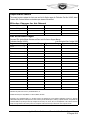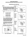
1
IGNITION SWITCHES
STARTER SWITCHES
AND DOOR LOCK KITS
CONTINENTAL® IGNITION SYSTEMS
SERVICE
SUPPORT
MANUAL
Publication X43002-1
©
2011 CONTINENTAL MOTORS, INC.
AUG 2011
Supersedure Notice
This manual revision replaces the front cover and list of effective pages for Publication Part No. X43002, dated
October 1989. Previous editions are obsolete upon release of this manual.
Effective Changes for this Manual
0 ............... October 1989
1 ............ 30 August 2011
List of Effective Pages
Document Title: Ignition/Starter Switches and Door Lock Kits Service Support Manual
Publication Number: X43002-1
Initial Publication Date: October 1989
Page
Change
Page
Change
Page
Change
Page
Change
Cover............................ 1
A................................... 1
B................................... 1
ii thru vi......................... 0
1 thru 11 ....................... 0
Published and printed in the U.S.A. by Continental Motors, Inc.
Available exclusively from the publisher: P.O. Box 90, Mobile, AL 36601
Copyright © 2011 Continental Motors, Inc. All rights reserved. This material may not be reprinted, republished, broadcast, or otherwise
altered without the publisher's written permission. This manual is provided without express, statutory, or implied warranties. The publisher will
not be held liable for any damages caused by or alleged to be caused by use, misuse, abuse, or misinterpretation of the contents. Content is
subject to change without notice. Other products and companies mentioned herein may be trademarks of the respective owners.
A
Ignition/Starter Switches and Door Lock Kits Service Support Manual
31 August 2011
Intentionally Left Blank
WARN
(Please note the following statements from FAA Advisory Circular 2 W 2 C entitled "EUGIBIUTY, QUALITY, AND IDENTIFICATION
OF APPROVED REPlACEMENTPAKIS):
3.
BACKGROUND. An increasingamount of replacement parts (including standard parts), materials,
appliances, and instruments are offered for sale as being of aircraft quality when actually the quality and
originof these unitsare unknown. Usersofsuch unttsareusuallynot awareof the potentialhazardsinvolved
with replacement parts that are not eligible for use on certificated aircraft. Frequently such units are
deceptively advertised or presentedas "unused,""iike new," or "remanufactured."lhis impliesthat the
quality of such units is equal to an original or appropriately repairedor overhauled unit.
The performance rules for replacement of parts and materials used in the maintenance and alteration of
U.S. certificated aircraft are specified in FederalAviation Regulations (FAR) 43.13 and FAR 145.57. The
responsibilityfor the continued airworthinessof the aircraft, which includes the replacement of parts, is the
responsibllityofthe ownerJoperatoras outlined in FAR 91.163, FAR 129.363, FAR 123.45, FAR 127.131
and FAR 135.143 (a).
4.
IDENTIFICATIONOF THE APPROVED PARTS. Approved serviceable replacement
parts are identified as follows:
a.
By an FAA Form 8130-3 (Formerly FAA Form 186), Airworthiness Approval Tag. An Airworthiness
Approval Tag identifies a part or group of parts that have been approved by authorized FAA
representatives.
b.
By an FAA Technical Standard Order (TSO) number and identiiicationmarkthat indicatesthe part or
appliance has been manufacturedunder the requirementsof FAR 37.
c.
By an FAAlPMAsymbol, together with the manufacturer's name, trademark or symbol, part number,
and the make and model of the type certificated product on which the part is eligible for installation,
stamped on the part. An FAA Parts ManufacturerApproval (FAAIPMA) is issued under FAR 21.305.
The make and model information may be on a tag attachedto the part.
d.
By shipping ticket, invoice, or other document which provides evidence that the part was produced
by a manufacturer holding an FAA Approved Production InspectionSystem issued under FAR 21,
Subpart F, or by a manufacturerholding an FAA ProductionCertificateissuedunder FAR 21, Subpart
G.
e.
By a certificate of aiworthiness for export issued by a foreign government under the provisions of
FAR 21, Subpart No
KNOW YOUR SUPPLIER. lt has come to our attention that many reproduced parts and
components, particularly instruments which have been manufactured by persons other than the original
manufacturer, are availablefor purchase and installationon U.S. certificatedaircraft. Often, an original part
is usedas a sample to produce duplicates. The reproducedpartsappear to be as good as the original part;
however, there are many unknown factors to be considered that may not be readily apparent to the
purchaser, i.e., heat treating, plating, inspections, tests and calibrations. All too often the faulty part is not
discovered until a malfunction or an accident occurs.
2-
SUMMARY. In accordance with FAR'S, certification of materials, parts, and appliancesforreturn
to servlce, for use on aircraft, is the responsibilityof the person or agency who signs the approval.
The owner/operator, as denoted in paragraph 3 of this advisory circular, is responsible for the continued
airworthiness of the aircraft. To assure continued safety in aircraft Operation, it is essential that great care
be used when inspecting, testing, and determining the acceptability of all parts and materials. Particular
caution should be exercised when the identity of materials, parts, and appliances cannot be established
or when their origin is in doubt.
ii
October, 3 989
System Support Manual
IGNITIONISTARTER SWITCHES AND DOOR LOCK KITS
TABLE OF CONTENTS
. . . . . . . . . . . . . . . . . . . . . . . . . . . . . . . . . . . . . . . . . . . . . . . . . . . . . . . . ii
INTRODUCTION . . . . . . . . . . . . . . . . . . . . . . . . . . . . . . . . . . . . . . . . . . . . . . . . . . . . iv
DESCRIPTION AND OPERATION . . . . . . . . . . . . . . . . . . . . . . . . . . . . . . . . . . . . . . . . . . v
DISASSEMBLY . . . . . . . . . . . . . . . . . . . . . . . . . . . . . . . . . . . . . . . . . . . . . . . . . . . . . 1
Disassemble lgnitionlstarter Switches . . . . . . . . . . . . . . . . . . . . . . . . . . . . . . . . . . . . . 1
Disassemble Type GM Switches . . . . . . . . . . . . . . . . . . . . . . . . . . . . . . . . . . . . . . . . 1
Disassemble Door Locks . . . . . . . . . . . . . . . . . . . . . . . . . . . . . . . . . . . . . . . . . . . . . 1
CLEANING AND INSPECTION . . . . . . . . . . . . . . . . . . . . . . . . . . . . . . . . . . . . . . . . . . . . 1
ASSEMBLY . . . . . . . . . . . . . . . . . . . . . . . . . . . . . . . . . . . . . . . . . . . . . . . . . . . . . . . . 2
Assemble IgnitionIStarter Switches . . . . . . . . . . . . . . . . . . . . . . . . . . . . . . . . . . . . . . . 2
Assemble GM Type Switches . . . . . . . . . . . . . . . . . . . . . . . . . . . . . . . . . . . . . . . . . . 2
TESTING . . . . . . . . . . . . . . . . . . . . . . . . . . . . . . . . . . . . . . . . . . . . . . . . . . . . . . . . . 3
Testing Ignitionlstarter Switches . . . . . . . . . . . . . . . . . . . . . . . . . . . . . . . . . . . . . . . . 3
Testing GM Type Switches . . . . . . . . . . . . . . . . . . . . . . . . . . . . . . . . . . . . . . . . . . . . 3
Testing Door Locks . . . . . . . . . . . . . . . . . . . . . . . . . . . . . . . . . . . . . . . . . . . . . . . . 3
WARNING
INSTALLATION
. . . . . . . . . . . . . . . . . . . . . . . . . . . . . . . . . . . . . . . . . . . . . . . . . . . . .4
ILLUSTRATED PARTS LIST . . . . . . . . . . . . . . . . . . . . . . . . . . . . . . . . . . . . . . . . . . . . . . 5
Equipment Covered . . . . . . . . . . . . . . . . . . . . . . . . . . . . . . . . . . . . . . . . . . . . . . . .5
Ignition Switches . . . . . . . . . . . . . . . . . . . . . . . . . . . . . . . . . . . . . . . . . . . . . . . . . 6
Switch and Door Lock Kits . . . . . . . . . . . . . . . . . . . . . . . . . . . . . . . . . . . . . . . . . . . . 8
Numerical Parts List . . . . . . . . . . . . . . . . . . . . . . . . . . . . . . . . . . . . . . . . . . . . . . . .10
Superseded and Discontinued Items . . . . . . . . . . . . . . . . . . . . . . . . . . . . . . . . . . . . . .ll
IgnRionSwitchiLeadingParticulars
Rated to handle magneto primary
voltage and/or 24 volts DC, 5 amps
1,000 volts DC to ground. Use
InsulationTest
11-8950-2High Tension LeadTester
Ki.
Has removable leverto facilitate
Lever Type Switch
mounting
Has disc tumbler iock with removable
Key Type Switch
key. Available with matching door
locks.
50 hr salt test per Fed. Spec.
CorrosionResistance
QQ-M-151-A
Lubrication
CramolinPasteType 20Kd
Adjustable for panelthickness to
Mounting
.312 in.
Position Indicating Dial Available as desired
7 02.
Weight
Housing
Die cast
Contacts
iii
October, 1989
System Support Manual
IGNITION/STARTER SVVITCWES AND DOOR LOCK KITS
INTRODUCTION
your localTCM distributor or TCM field representative.
Requests for copies of Teledyne Continental Aircraft
Engine Service publications should be made through
your distributoror Teledyne Continental Motors, P. 0.
Box 90, Mobile, AL 36601, Attn: Publications Department.
GENERAL
A.
This manual provides complete maintenance instructions with illustrated parts list for IgnitionIStarter
Switches and Door Lock Kis, manufactured by
Teledyne Continental Motors, Aircraft Products, Mobile, Alabama 36601. TCM lgnition Switches control
magneto operation. Many switches also include con- D. Good standardshop practices and safety precautions
trols for starting and eledric primer circuits. Door
should be observed at all times to avoid damage to
locks are usedto secure cabin doors andlor baggage
equipment and or injury to personnel.
compartment doors. Switch and door lock kits incorporate matching lock mechanisms and are operated E. All maintenance instructions inthis manualhave been
by a single key for maximum convenience.
shop verified. Shop verified procedures are those by
which the manufacturer has accomplished all DisasB. This manual is subdivided with sub-heads as listed in
sembly, Assembly, Testingand Fault Isolationby perthe Table of Contents. Revision service may be proforming the functions described in this manual on
vided by ordering Master Service Manual Form
equipment identical in configurationto that described.
X40000. TCM Ignition Systems Service Bulletins includedin Master Sewice Manualprovidecurrent infor- F. Dimensions are given in Standard Units. For refermation related to service, maintenance and technical
ence, abbreviations used are listed in Table 1.
support of the product. Service Bulletins 583 and 615
have been incorporated intothis manual. This manual G. Numbers in parentheses following part nomqnclature
refer to item numbers in illustrated Parts Llst Figure 1
may be includedin Chapter 74-30of applicableGAMA
format publications.
and 2 unless otherwise specified. Example: (1-5) is
item 5 in IPL Figure 1;(2-1) is item 1 in IPL Figure 2.
C. These instructionsdo not cover all details or variations
in equipment nor do they provide for every possible Recommendations, cautions and warnings regarding
contingency to be met in connection with installation, maintenanceof this equipment are not intendedto impose
operation, or maintenance. Shouldfurther information undue restrictions. They are inserted to obtain maximum
be desired or particular problems arise which are not performancefromthe equipment in accordance with safety
covered sufficiently for purchaser's purpose, contact and efficiency. Abuse, misuse, or neglect of any piece of
equipment can cause eventual failure. For an aircraft enTable 1
gine it is obvious that a failure may have disastrous conseAbbreviations
quences. Failure to observe the instructions contained in
this manual constitutes unauthorized operation in areas
unexplored during development of the engine, or in areas
in which experience has proved to be undesirable or detrimental.
Pound Inches
lb in.
NOTES, CAtmONS and WARNINGS are included
Pound Fource
Ibf
throughout this manual. Application is as follows:
I
II
I
I
Pounds per Hour
PPh
1
NOTE. ..Special interest informationwhich may facilitate
the operation of equipment.
I
Pounds per Square InchGage
Psis
I
CAUTION. . . lnformation issued to emphasize certain
imtructions or to prevent possible damage to engine or
accessories.
I
I
Gallons
ft
gal
II
I
ounces
oz
I
Feet
iv
October, 1989
..
Information which, If disregarded, rnay
result insevere damageto or destnrctionof the engine
or endangementto personnet.
WARNING.
System Support Manual
IGNITIONISTARTER SWITCHES AND DOOR LOCK KITS
DESCRIPTION AND OPERATION
GENERAL
Twist to Start
A.
With 2 Keys
10357200-1
Ignition switches manufactured by Teledyne Continental Motors, Aircraft Products, Mobile, Alabama
36601 are designed to provide control of magneto
operation. Optional starter solenoid control, electrical
primer control, and key or lever designs are available
as shown in Figure 1.
10357200112
with 2 Cessna Keys
10357230-1
Lwer Type
B. The various switch position functions are listed
10357BO-1
Lever Type, without
Lever
below*.
OFF
Both magnetos inoperative
R
Right magneto operating
Left magneto inoperative
Push to start
10357210-1
with 2 Keys
L
BOTH
Left Magneto operating
Right magneto inoperative
1 0357210-9
with 3 Keys
Both magnetos operative
10-357240-1
Lever Type
START Battery terminal connected to starter
solenoid through start terminal. Rlght magnet0 may be grounded with jumper behnreen
right terminals. Left magneto main and retard
contacts may be connected to starting vibrator output. Spring return to both position.
Twist to Start
Push to Prime
PUSHTOPRIME Allows aircraft to be electrically primed either in BOTHor START position. Spring loaded to normally open circuit
position.
10-357220-1
with 2 Keys
10357250-1
Lever Type
C.
Typical ignition switch mounting dimensions are
shown in Figure 2. Dimensions are in inches.
10357290-1
with 2 Keys
10357290-13
I
Figure 2. S w k h Dimensions
with 2 Cessna Keys
Figure 1. Switch Functions
V
October, 1989
System Support Manual
IGNITION/STARTER SWITCHES AND DOOR LOCK KITS
D. Ignitionswitch placard indicator dials are available for
each type of switch.
E.
Door locks are supplied in kiis as listed in Illustrated
Parts List. Door locks supplied with key-actuated
switches are actuated by the same key. Door locks
listed in Illustrated Parts List are also available separately and, when purchased this way, will have their
own key. If a door lock or switch becomes damaged,
a new one may be purchased separately.
Key PK number
stamped in this area.
MAINTENANCE RECOMMENDATIONS
A.
Ignition switch maintenance is conducted on an oncondition basis. Whenever access allows, components should be inspected for positive operation,
wear, binding, looseness or burning. Replace components as necessary.
8.
For key operated switches, due to the danger of
removing the key from the switch in other than the I
"OFF" position, switch locks (1-20) utilizing keys
marked with PK number code listed inTable 2 marked
as shown in Figure3 should be removedand replaced C.
at customer's earliest convenience. If key is not
marked with PK number code, refer to outside face of
any matching door locks.
Table 2
PK-502.
525,
553,
PK-605,
643,
PK-722,
755,
777,
PK-800,
860,
887.
PK-901,
967,
503,
528,
563,
606,
646,
729,
756,
784,
805,
862,
889,
914,
968,
K N PK NUMBER CODES
504, 506, 507, 511, 512, 513,
530, 532, 533, 536, 537, 539,
565, 572, 573
613, 616, 617, 618, 627, 639,
648, 650, 653, 657, 660, 667,
731, 734, 735, 736, 738, 743,
758, 760, 763, 765, 766, 767,
786, 798
807, 814, 846, 848, 850, 852,
869, 872, 873, 876, 880, 881,
890, 891, 894
916, 921, 922, 923, 930, 956,
970, 971, 978, 985, 990, 992,
p d)--
'~emoveMack rubber from top of key
to expose the PK number.
Figure 3. PK Number Location
For all switches with start position, to ensure positive
grounding of magnetos when in "OFF" position, old
support (1-2) shoud be replaced with current design
support (1-2) at customer's earliest conveneince. Current design support includes oversize rivet head as
shown in Figure 4. Current support (1-2) is identified
with white paint mark on terminal lug side of support.
523, 524,
544, 551,
641, 642,
682
744, 745,
773, 774,
.22 in dia.
853, 855,
882, 884,
963, 966,
996, 997,
Figure 4. Current Support (1-2) IgnitionIStarter
Switches
vi
October, 1989
1
System Support Manual
IGNITIONISTARTER SWITCHES AND DOOR LOCK KITS
MAINTENANCE INSTRUCTIONS
DISASSEMBLY
NOTE:
I(
Complete disassembly is not necessary in all
instances. Only disassemble switch to the extent necessaryfor repairs.
A.
C.
Locks
Do not attempt disassembly of door locks.
CLEANING AND INSPECTION
A.
Clean all switch partsthoroughly with trichlorethylene
or other suitable solvent.
B.
(1) On switches which incorporate a lever, remove
lever (1-15) by removing screw (1-13) and
lockwasher (1-14) from shaft (1-18). Remove nut
(1-16 or 1-17) and dial (1-22) if used. Remove
switch from panel and remove all wires from
switch terminals. (On key actuated switches C.
begin disassembly with removal of nut (1-16 or
1-17) and dial (1-22) if used.)
Inspect switch rotor (1-7) and contact support (1-2,
1-2a) for cracks and check contact surfaces for
grooves or excessive wear. Inspect switch contact
bracket (1-9) and switch contacts (1-3, 1-3a) for excessive wear, corrosion or deformation.
Disassemble IgnitionIStaiterSwitches:
lnspect lock assembly and key (1-20) for wear. When
key is inserted,the brasstumblers should beflushwith
barrel. Small extensions may be filed off, or a new key
may correct this condition.
(2) Remove self-tapping screws (1-1) and pull off
support (1-2). Take out switch contacts (1-3) and D. Ifpositioningspring, which is in switch housing (1-21),
spring (1-4). Remove self-tapping screw (1-1),
is broken, has weak spring tension or shows signs of
lockwasher 41-5) and plain washer (1-6) from
considerablewear, replace switch housing (1-21).
center of rotor (1-7).
(3) Removelockassembly (1-20) or shaft (1-18)from
front of switch. Pull rotor (1-7) from housing (121). L i spring (1-11) and retainer (1-12) from
rotor (1-7).
(4) The 10-357210 series switches incorporate a
bushing (1-19) on end of lock assembly. Slide
bushing from end of this assembly.
(5) If used, pull pin (1-8) from rotor (1-7). Remove
bracket (1-9) and spring (1-10,1-1 Oa).
B.
DisassembleType GM Switches(10-357290Series):
(1) Remove knurled nut (1-16) and dial (1-22) from
switch. Remove switch from panel and disconnect wires fromterminalsby removingnuts (1-28)
and lockwashers (1-5a). Remove hex nut (1-17).
Remove two screws (1-1) which secure switch
contact support (1-2) to housing (1-21). Lift two
contact brackets (1-9) and coil springs (1-10a)
from switch rotor (1-7a). Remove screw (1-I),
lock washer (1-5a) and flat washer (1-6a) which
secure rotor (1-7a) to switch lock assembly (120). Switch lock assembly can now be removed
from the housing.
I
1
October,1989
System Support Manual
IGNITIONISTARTER SWITCHES AND DOOR LOCK KITS
B.
ASSEMBLY
NOTE:
(1) Assemble contacts (1-3a, 1-3b), screws (1-25,
1-26), washers (1-27,16a) and nuts (1-28) onto
support (1-2a). Apply 8-11 Ib. in. torque to each
inner nut (1-28).
During assembly, sparingly apply Cramolin
paste type 20Kd* to contact (1-3) face, to
bracket (1-9) contact surfaces and to contact
side of support (1-2,I-2a) assemblies. A dab of
this paste may also be applied to positioning
spring in housing (1-21) and to lock (1-20) key
teeth.
A.
Assemble GM Type Switches
(2) Align rotor (1-7a) in housing (1-21) as shown in
Figure 5. Seat rotor (1-7a) completely into housing (1-21).
Assemble IgnitionlStarterSwitches
I
(1) If used, assemblespring (1-10),bracket (1-9)and
pin (1-8) into rotor (1-7).
(3) Insert bck plug (1-20) into rotor (1-7a) and assemble screw (1-I), lock washer (1-5a) and
washer (1-6a) into rotor (1-7a) and lock plug
c;POSITIONING
SPRING
(2) Assemble radial tang of spring (1-11) into rotor
(1-7) groove.
(3) Assemble spring retainer (1-12) hole onto axial
tang of spring (1-11) with boss on retainer (1-12)
towards rotor (1-7). Wind retainer (1-12) counterclockwise until retainer arm rests in recess in
rotor (1-7).
(4) Orient rotor (1-7) assembly so ridged portion
I
aligns with positioning spring in housing (1-21).
Referto Figure 5. Seat rotor (1-7) completely into
housing(1-21).
Figure 5. Proper Positioning of Rotor
(1-20) tighten and adjust screw (1-1) to allow no
binding during switch operation and minimal end
play. If this is not possible, replace lock plug
(1-20).
-
(5) Assemble bushing (1-19) (if used), lock plug (1
20) or shaft (1-18) into housing (1-21) and rotor
(1-7) assembly. Chamfered edges on iock plug
(1-20) and shaft (1-18) allow parts to be assembled only one way. During assembly, support
rotor (1-7) with fingers to prevent pushing it back
out of housing (1-21). Assemble washer (1-6),
lockwasher (1-5) and screw (1-1) into rotor (1-7)
and lock plug (1-20) or shaft (1-18). Tighten and
adjust screw (1-1) to allow no binding during
switch operation and minimal end play. If this is
not possible, replace lock plug (1-20) or shaft
(1-18).
(4) Assemble springs (1-1Oa) and brackets (1-9) into
rotor (1-7a). Brackets(1-9) should slidefreely into
and out of rotor (1-7a) and should be aligned as
shown in Figure 5.
(5) Align boss on support (1-2a) with notch in housing (1-21) and assemble with two screws (1-1).
(6) Test switch in accordance with Testing procedures.
(6) Insert springs (1-4) into recesses in rotor (1-7).
Assemble contacts (1-3) onto springs (1-4). Align
boss in support (1-2) with notch in housing (1-21)
and assemble with two screws (1-1).
(7) Test witch in accordance with Testing procedures.
I
"CramdinPaste Type 20Kd available in 1 oz. can,Catalog No. P-200-K1,tom Caig Laboratwies, 17750 lndusfriai Ave. (P. 0.Box J), Escondido, CA
920250051.
I
System Support Manual
IGNITIONISTARTER SWITCHES AND DOOR LOCK KITS
TESTING
B.
GENERAL:
Following assembly, test switch for positive operation. Action must be smooth, without sticking. Keys must be removable in only the "OFF position. Test switch electrical
operation as described in paragraph A and B below. If
switch fails tests, check for incorrect assembly or bent..
C.
switch contact brackets.
A.
Testing GM Type Switches
(1)
Using 11-8950-2 tester or equivalent, check
for continuity as shown in Table 4.
(2)
Perform high voltage insulation test as described in paragraph A(2) above.
Replacedoor lock or key if lock binds during operation
or if key is removable in intermediate positions.
Testing lgnitionlstarter Switch
(1) Using the 11-8950-2 Tester or equivalent, check
for continuity between each terminal and all other
terminals, and between each terminal and housing, in all switch positions. Table 3 indicates terminals which shall have continuity. If there is
continuity between any other terminals and/or
housing, the switch shall be rejected. It is not
necessary to check continuity between the two
terminals at R.
NOTE:
Table 4. GM Type Switch Logic
Lower "R"terminal is grounded in start position.
See Figure G.
(2) Using the 11-8950-2 Tester or equivalent, make a
highvoltage test of insulationresistance between
each terminal and all others that are open circuited, and between each terminal and housing
in all switch positions.
NOTE:
Unless switch is push-to-prime type, PR terminal is not used.
(Push to Prime)
L and GRD
R and GRD
BAT and S; R and GRD; L, LR and BO
Table 3. IgnitionlStarter Switch Logic
3
October, 1989
System Support Manual
IGNITIONISTARTER SWITCHES AND DOOR LOCK KITS
INSTALLAVON
A.
B.
Using the pertinent illustration in Figure 6, conned
wires to their proper terminals using screws (1-24) or
nuts and lock washers (1-28,l-5a). If right magneto is
to be grounded during start, attach lug terminal (1-23) C.
across terminals nearestthe "R" mark.
Connectionsto the terminals are as follows:
GRD
R
L
LR
BO
S
BAT
PR
Ground
Right Magneto "P" Lead
Left Magneto "P" Lead
Left Magneto Retard Lead
Booster Output (Starting Vibrator)
Starter Solenoid
Battery
Primer Solenoid (Used only on
switches with "pushto prime"feature incorporated.)
TWIST-TO-START AND
PUSH-TO-PRIME TYPES
PUSH-TO-START TYPE
USH-TO-START
Figure 6. Switch Terminal Locations
4
October, 1989
Lever (1-15) must be removed prior to installation of
lever type switches. To remove lever (1-15), remove
screw (1-13) and lock washer (1-14) and pull lever
(1-15) straight off.
Following lever removal, installation procedures for
lever and key type are the same. The switches are
installed from the rear of panel through a 15/16 inch
hole with an alignment lug which fits in groove in
switch housing. Recommended maximum panel
thickness is 0.31 2 inches.
D.
Removeknurled nut (1-16), and seat hex nut (1-17) as
close as possible to switch housing (1-21).
E.
Insert switch assembly through hole in panel with
keyway in switch aligned with lug. If it is desirable to
install a position indicating dial (1-22) it must be in
stalled over and aligned with the keyway in the
threaded end of housing extendingfrom controlpanel.
F.
Tighten round knurled nut (1-16) over threaded portion of switch. If possible secure switch firmly in place
by tightening hex nut (1-17) against rear of panel.
Complete assembly is shown in Figure 7.
System Support Manual
IGNITION/STARTER SWITCHES AND DOOR LOCK KITS
IGN~ION$WITCHES
IGNITION SWITCH AND DOOR LOCK KlTS
DOOR LOCK KlTS
IPL TABLE 1: EQUIPMENT COVERED
See
Descttptfon
Part NO.
IPL Fig.
No.
Keys
Switch Only, Key Type, Twist to Start
Switch and Door Lock Kit
Switch and Door LockKi
Switch Only, Key Type, Twist to Start
Switch and Door Lock Kit
Switch and Door Lock Kit
Switch and Door Lock Ki
Switch and Door Lock Ki
Switch and Door Lock Kit
Switch and Door Lock Kit
Switch Only, Key Type, Pushto Start
Switch Only, Key Type, Pushto Start
Switch and Door Lock Ki
Switch and Door Lock Ki
Swich and Door Lock Ki
Switch and Door Lock Kit
Switch Only, Key Type, Twist to Start, Pushto Prime
Switch Only, LeverType, Twist to Start
Switch Only, Lever Type, Pushto Start
Switch Only, Lever Type, Twist to Start, Push to Prime
Switch Only, Lever Type (Wihout Lever), Twist to Start
Switch Only, Key Type, GM (No Start Position)
Switch and Door Lock Kit
Switch and Door Lock Ki
Switch and Door Lock Ki
Switch Only, Key Type, GM (No Start Position)
Door Lock Ki
Door Lock Kit
Door Lock Ki
* Keysmarked"CESSNA"
5
October, 1989
System Support Manual
IGNITION/STARTER SWITCHES AND DOOR LOCK KITS
IPL TABLE 2: IGNITION SWITCHES
6
October, 1989
1 ITEMS 25 THROUGH 5a (QTY 6) INCLUDED WITH KEM 2a
* NOT AVAILABLE AS A SPARE. SHOULD REPLACEMENT BE NECESSARY, REPLACE ENTIRE SWITCH.
** DIAL NOT SUPPLIED WITH SWITCH, PURCHASE SEPARATELY AS INDICATED.
System Support Manual
IGNITION/STARTER SWITCHES AND DOOR LOCK KITS
IPL Figure t. Exploded View of Switches
7
October, 1989
System Support Manual
IGNITIONISTARTER SWITCHES AND DOOR LOCK KITS
IPL TABLE 3. IGNITION SWITCH AND DOOR LOCK KITS
" Keys marked "CESSNA"
" Dial not supplied with kit
8
October, 1989
System Support Manual
IGNITIONISTARTER SWITCHES AND DOOR LOCK KITS
IPL Figure 2. Ignition Switch and Door Lock Kits
9
October, 1989
System Supporl Manual
IGNITIONISTARTER SWITCHES AND DOOR LOCK KITS
IPL TABLE 4. IGNITION SWITCH AND DOOR LOCK KITS
NUMERICAL PARTS LIST
Part
Number
10-377028
10
October, 1989
Nomenclature
support
Dial
Screw and Lock Washer
Terminal -Lug
Screw
Dial (Twist to Start)
Dial (Twist to StarVPushto Prime)
Dial (Push to Start)
Door Lock and 2 Keys
Door Lock and 2 Keys
Support Kit
Support Kit
Door Lock and 2 Keys
Door Lock and 2 Keys
Door Lock and 2 Keys
Door Lock and 2 Keys
Door Lock and 2 Keys
Figureand
Item No.
2-3f
System Support Manual
IGNITION/STARTER SWITCHES AND DOOR LOCK KITS
IPL TABLE 5: SUPERSEDED AND DISCONTINUED ITEMS
OLD PIN
10-32890-1
10-34365
10-51104
10-51104-1
10-51150-1
10-51150-2
10-51160
10-51180-1
10-81388-1
10-126630-1
10-126630-4
10-126660-1
10-126660-4
10-126680-1
10-126680-2
10-126680-6
10-126690-1
10-126690-2
10-126690-4
10-126690-6
10-126690-8
10-126690-11
10-126690-12
10-126690-13
10-126690-14
10-126690-15
10-157440-1
10-157440-2
10-157440-3
10-1574404
10-757440-21
10-357200-2
10-357200-3
10-357200-4
10-357200-5
10-357200-6
10-357200-7
10-357200-8
10-357200-9
10-357200-13
10-357200-14
10-357200-15
10-357200-16
10-357200-17
SUPERSEDEDBY
4
t
t
10-357290-1
t
t
t
t
10-357230-1
t
10-357250-1
t
10-357220-1
10-357210-1
t
10-357200-1
Supetseding PlFI may be supplied upon request.
t
t
t
t
*
t
t
*
t
t
t
*
t
t
*
*
*
t
t
t
t
t
*
*
OLD P/N
10-357200-19
10-357200-21
10-357210-2
10-357210-3
10-357210-4
10-357210-5
10-357210-6
10-357210-7
10-357210-8
10-357210-11
10-357230-2
10-357260-2
10-357260-3
10-357260-4
10-357260-5
10-357260-6
10-357260-7
10-357270-1
10-357270-2
10-357270-3
10-357270-4
10-357270-5
10-357270-6
10-357270-7
10-3572708
10-357270-9
10-357270-10
10-357270-11
10-357280-1
10-357280-2
10-357290-2
10-357290-3
10-357290-4
10-357290-5
10-357290-6
10-357290-7
10-357290-11
10-357290-14
10-357290-15
10-357290-16
10-357310-1
10-357310-2
10-357310-3
10-357310-4
10-357310-5
SUPERSEDEDBY
t
t
t
t
t
t
*
t
t
.c
*
t
t
*
t
t
t
t
t
t
t
t
t
t
t
t
t
t
t
t
t
t
t
t
t
t
t
t
t
t
t
11
October, 1989
www.continentalmotors.aero