1
Technical Reference Hardware Version 10.01 - May 2009 Production & Playout Server XT Series DISK RECORDER - Version 10.01 - Hardware Technical Reference Manual EVS Broadcast Equipment SA – May 2009 Issue 10.01.A C OPYRIGHT EVS Broadcast Equipment – Copyright © 2002-2009. All rights reserved. D ISCLAIMER The information in this manual is furnished for informational use only and subject to change without notice. While every effort has been made to ensure that the information contained in this user manual is accurate, up-to-date and reliable, EVS Broadcast Equipment cannot be held responsible for inaccuracies or errors that may appear in this publication. I MPROVEMENT R EQUESTS Your comments will help us improve the quality of the user documentation. Do not hesitate to send improvement requests, or report any error or inaccuracy on this user manual by e-mail to [email protected] . i Issue 10.01.A XT Series DISK RECORDER – Version 10.01 - Hardware Technical Reference EVS Broadcast Equipment SA – May 2009 Table of Contents TABLE OF CONTENTS .................................................................................................... II WHAT’S NEW? ................................................................................................................. V 1. OVERVIEW............................................................................................................... 1 1.1 XT[2] HIGH-RESOLUTION SERVER...........................................................................................1 1.2 XT[2] PROXY SERVER ...............................................................................................................2 1.3 UNPACKING................................................................................................................................2 1.4 DIMENSIONS ..............................................................................................................................2 1.5 INSTALLATION............................................................................................................................5 1.6 SAFETY, COMPLIANCE AND OPERATING CONDITIONS........................................................6 1.6.1 Safety......................................................................................................................................6 1.6.2 EMC Standards.......................................................................................................................6 1.6.3 EMC Warning..........................................................................................................................7 1.6.4 CE Marking .............................................................................................................................8 1.6.5 Power Supply..........................................................................................................................8 Cold Swap..................................................................................................................................................................8 Hot Swap....................................................................................................................................................................9 Secondary Power Supply .........................................................................................................................................10 Grounding ................................................................................................................................................................10 1.7 VENTILATION & RACK MOUNTING .........................................................................................10 1.8 HARDWARE CONSUMPTION...................................................................................................11 1.9 XT[2] SERVER MAIN SPECIFICATIONS ..................................................................................13 1.9.1 Video.....................................................................................................................................13 1.9.2 Audio.....................................................................................................................................13 1.9.3 Video Codecs & Bitrates .......................................................................................................14 1.9.4 Recording Capacity for XT[2] Servers...................................................................................14 1.9.5 Power Consumptions ............................................................................................................16 1.9.6 Supported SMPTE Standards...............................................................................................16 1.9.7 Maximum Bitrate values........................................................................................................16 1.9.8 AVID DNxHD ® and APPLE ProRes 422..............................................................................17 Introduction ..............................................................................................................................................................17 Video Bitrate Compatibility with Avid and Apple Products .......................................................................................17 Choices of Bitrates when using Avid DNxHD® or Apple ProRes 422 with EVS XT[2] servers................................18 Important Recommendations ...................................................................................................................................22 1.9.9 Raid level: 3 ..........................................................................................................................23 1.9.10 Interpolation ..........................................................................................................................23 2-line Interpolator .....................................................................................................................................................24 4-line Interpolator .....................................................................................................................................................24 2. CABLING................................................................................................................ 25 2.1 XT[2] 6U BACK PLANE, MULTICAM MODE .............................................................................25 2.2 XT[2] 4U BACK PLANE..............................................................................................................26 2.3 GPI IN CONNECTIONS.............................................................................................................27 2.3.1 Relay Æ Opto inputs on the XT server (GPI inputs 1, 2, 3, 4)..............................................27 2.3.2 Relay Æ TTL inputs on the XT Server (GPI inputs 5, 6, 7, 8)...............................................27 2.3.3 TTL Æ TTL inputs on the XT server (GPI input 5, 6, 7, 8)....................................................28 2.4 GPI OUT SETTINGS .................................................................................................................28 ii XT Series DISK RECORDER - Version 10.01 - Hardware Technical Reference Manual EVS Broadcast Equipment SA – May 2009 Issue 10.01.A 2.5 MTPC GPIO CONNECTOR 15/10/02 ........................................................................................29 2.5.1 GPIO Connector: SUB-D 25-pins Male .................................................................................29 2.5.2 GPIO hardware specification ................................................................................................30 2.6 RS422 CONNECTOR OF THE REMOTE CONTROL PANEL...................................................31 2.7 AUDIO CONFIGURATIONS ......................................................................................................32 2.7.1 CODA FOR XT[2]..................................................................................................................32 2.7.2 PIN ASSIGNMENT ON SUB-DB15 CONNECTORS ............................................................32 2.8 CONNECTING MULTIPLE XT[2] SERVERS ON XNET ............................................................33 2.8.1 Connection diagram without EVS XHub SDTI HUB ..............................................................34 2.8.2 Connection Diagram With EVS XHub SDTI HUB..................................................................35 2.8.3 Required conditions to set up and run XNet..........................................................................36 2.8.4 Starting XNet.........................................................................................................................37 2.8.5 XNet Performances & Troubleshooting.................................................................................38 2.9 GIGABIT NETWORK .................................................................................................................39 2.9.1 Functional Overview..............................................................................................................39 2.9.2 Backup of Clips .....................................................................................................................40 2.9.3 Restore of Clips ....................................................................................................................41 2.9.4 Switches................................................................................................................................42 Supported Switches .................................................................................................................................................42 Comparison..............................................................................................................................................................43 Additional information...............................................................................................................................................43 2.10 REDUNDANT IPDP SERIAL LINK.............................................................................................44 3. HARDWARE DESCRIPTION ................................................................................. 45 3.1 BOARDS AND SLOT CONFIGURATIONS................................................................................45 3.1.1 6U Frame ..............................................................................................................................45 3.1.2 4U Frame ..............................................................................................................................45 3.2 VIDEO AND REFERENCE BOARDS ........................................................................................46 3.2.1 COHX Board .........................................................................................................................46 Jumpers on the COHX base module .......................................................................................................................47 Leds on the COHX base module with genlock.........................................................................................................48 Leds on the COD A and COD B modules (from left to right)....................................................................................48 Connectors on the COD A and COD B modules .....................................................................................................49 Channel Assignment ................................................................................................................................................50 3.3 AUDIO CODEC BOARD ............................................................................................................52 LED information and connector................................................................................................................................52 3.4 RAID CONTROLLER BOARDS .................................................................................................53 3.4.1 HCTX board ..........................................................................................................................53 Jumpers ...................................................................................................................................................................54 LEDs ........................................................................................................................................................................54 Connectors...............................................................................................................................................................55 Gigabit Connectors ..................................................................................................................................................56 3.4.2 RTCL Board on Disk Array (with HCTX) ...............................................................................56 LEDs ........................................................................................................................................................................57 3.4.3 External RAID Array XT-HDX for XT[2] Server .....................................................................58 XT-HDX dimensions.................................................................................................................................................58 Installation and operation .........................................................................................................................................59 Disk organisation......................................................................................................................................................60 LED Status ...............................................................................................................................................................60 How to replace a Disk ..............................................................................................................................................61 3.5 MTPC BOARD ...........................................................................................................................62 3.5.1 Introduction ...........................................................................................................................62 3.5.2 A2/A3 and A2/A4 Board ........................................................................................................63 LED information: ......................................................................................................................................................63 Board configuration: .................................................................................................................................................63 3.5.3 Memory Hole Activation ........................................................................................................64 REGIONAL CONTACTS ................................................................................................. 66 iii Issue 10.01.A iv XT Series DISK RECORDER – Version 10.01 - Hardware Technical Reference EVS Broadcast Equipment SA – May 2009 XT Series DISK RECORDER - Version 10.01 - Hardware Technical Reference Manual EVS Broadcast Equipment SA – May 2009 Issue 10.01.A What’s New? Some sections may have been reviewed even if no specific changes related to these sections have been brought on Multicam version 10.00. The changes linked to new features on Multicam version 10.00 appear with the ‘New’ logo in the table below: Main manual updates for Multicam version 10.00 1.1 Use of XT[2] as a Proxy Server 1.4 Additional information on XT[2] server dimensions 1.6 Updated information on Safety, Compliance and Operating Conditions 1.8 Data on hardware consumption 1.9.2 1.9.3 16 audio channels per video Support of Mpeg-2 Intra 2.6 Technical specifications on the RS422 connector 2.9.4 Supported switches with the GigE network 2.10 Redundant IPDP Serial Link 3.5 MTPC Boards supported with Multicam 10.01 3.5.1 RJ45 and Header 26 connectors added on MTPC board schemas v XT Series DISK RECORDER – Version 10.01 - Hardware Technical Reference Manual EVS Broadcast Equipment SA – May 2009 Issue 10.01.A 1. Overview Welcome in the EVS range of products and thank you for using an EVS XT[2] server. We will do our best to satisfy your video production needs and we look forward to continuing working with you. The EVS XT[2] series servers are full digital in PAL (625i), NTSC (525i), 720p or 1080i standards. These multi-channel, disk-based video servers are ideal for a wide range of broadcast applications, from sports and live production to playout and transmission. 1.1 XT[2] HIGH-RESOLUTION SERVER The XT[2] server is typically used as a high-resolution server with various third party controllers, applications and automation systems using industry-standard protocols: Sony BVW75, Louth VDCP, Odetics, DD35, or EVS’ own API (AVSP). XT[2] series servers can also be controlled by EVS applications: Live Slow Motion (LSM) for sports production, including replays, highlights editing, and analysis tools like Split Screen to compare 2 synchronized actions side by side, Target Tracking and Painting to highlight a particular detail or provide tactical explanations IPDirector: a suite of Windows software applications designed to manage networked XT series servers. Its applications make it possible to control multiple channels within the XNet network, as well as to log an event, to create and manage clips and play-lists with advanced functions, among others to extract 1 Issue 10.01.A XT Series DISK RECORDER – Version 10.01 - Hardware Technical Reference EVS Broadcast Equipment SA – May 2009 clips from a VTR It also provides extensive database search features. AirBox: a Windows GUI to manage clips and play-lists with various advanced functions like loop playback, conditional transitions, etc. 1.2 XT[2] PROXY SERVER From Multicam V10.01, a low-resolution option can be set up to use the XT[2] server as a proxy server only. The Proxy servers can be run on large production events as the counterparts of the high-resolution servers. In this case, they need to be included in an XNet network distinct from the high-resolution XNet network. The XT[2] proxy servers are used for browsing purposes and can be controlled by IPDirector or EVS’ own API (AVSP) protocols. 1.3 UNPACKING On receipt of the equipment examine packing for obvious signs of damage. If damaged, do not unpack and inform the carrier immediately. Check thanks to the included packing list if all the items are present and if they show any mechanical damage. If yes, report damage or the missing parts to EVS or their appropriate representative. 1.4 DIMENSIONS Video disk recorder Main frame 19 inches Rack mount 6U – Weight: 32.5 Kg/ 71.5 Lbs. 2 XT Series DISK RECORDER - Version 10.01 - Hardware Technical Reference Manual Issue 10.01.A EVS Broadcast Equipment SA – May 2009 Rack mount 4U: Height: 170 mm The following table specifies the var ious lengths: Cold swap (without redundant pow er supply) Description Length (mm) Length (inch.) Rackable length (from behind the rack mounting stripes to the back of the server) 603 23,7 Length without the front panel 627 24,7 Length with the handles 660 26,0 Length with the front panel 670 26,4 Description Length (mm) Length (inch.) Rackable length (from behind the rack mounting stripes to the back of the server) 640 25,2 Length without the front panel 662 26,1 Length with the handles 695 27,4 Length with the front panel 705 27,7 Hot swap (with redundant power supply) Hot swap power supplies sticks out by 25mm / 1’’ (H: 187mm / 7.2’ by W: 170mm / 6.65’) Rack mounting stripes: L: 270 mm / 10.6” by W 21 mm / 0.8” Handles: H: 55mm / 2.2” by L: 160 mm / 6.3” by W: 21 mm / 0.8” 3 Issue 10.01.A XT Series DISK RECORDER – Version 10.01 - Hardware Technical Reference EVS Broadcast Equipment SA – May 2009 XT-HDX For more information on the XT-HDX, refer to section 3.4.3 “ External RAID Array XT-HDX for XT[2] Server ” , on page 58. Remote Control Panel Weight: 2.9 Kg / 6.3 Lbs. 10” Touch Screen Video Monitor Weight: 3.6 Kg / 7.8 Lbs. 4 XT Series DISK RECORDER - Version 10.01 - Hardware Technical Reference Manual EVS Broadcast Equipment SA – May 2009 Issue 10.01.A 18” Touch Screen Video Monitor Weight: 11.0 Kg / 23.9 Lbs. Keyboard - Weight: 0.4 Kg / 0.9 Lbs. Tablet - Weight: 0.5 Kg / 1.2 Lbs. 1.5 Ref: Wacom® GD0405R I NSTALLATION Important Verify the disk recorder unit has the correct voltage specifications for your power source prior to applying power. (selectable 110/230 VAC on the rear panel of the power supply, or autoswitch, depending on the type of power supply unit installed) Main power switch is located at the front side (lower right corner) of the unit. Before turning on the power, open the front door of Video disk recorder unit to check if all boards fit into their guides. If a board is out of its guides, remove carefully the board and replace it in the same slot. 5 Issue 10.01.A XT Series DISK RECORDER – Version 10.01 - Hardware Technical Reference EVS Broadcast Equipment SA – May 2009 1.6 SAFE TY, COMPLIANCE AND OPERATING CONDITIONS 1.6.1 SAFETY This equipment has been designed and tested to meet the requirements of the following: EN 60950 European Safety of information technology equipment including business equipment. IE C 950 International Safety of information technology equipment including business equipment. In addition, this equipment has been designed to meet the following: UL 1950 - USA 1.6.2 6 USA Safety of information technology equipment including business equipment EMC STANDARDS E N 55022 European Emission Standard E N 61000-3-2 European Electromagnetic Compatibility (EMC) Part 3 (Limits); Section2 ; limits for harmonic current emissions (equipment input current <16A per phase) EN 61000-3-3 European European Electromagnetic Compatibility (EMC) Part 3 (Limit s), Section 3; limitation of voltage fluctuation and flic ker in low-voltage supply systems for equipment with rated current of 16 A. EN 61000-4-3 European European Electromagnetic Compatibility (EMC) Part 4 (Limits), Section 3; Testing and measurement techniques - Radiated, radio-Frequency, electromagnetic field immunity test. EN 61000-4-4 European European Electromagnetic Compatibility (EMC) Part 4 (Limits), Section 4; Testing and measurement techniques - Electrical fast transient/burst immunity test. EN 61000-4-5 European European Electromagnetic Compatibility (EMC) Part 4 (Limits), Section 5; Testing and measurement techniques - Surge immunity test. XT Series DISK RECORDER - Version 10.01 - Hardware Technical Reference Manual EVS Broadcast Equipment SA – May 2009 1.6.3 Issue 10.01.A EN 55022 European Emission Standard EN 61000-4-6 European European Electromagnetic Compatibility (EMC) Part 4 (Limits); Section 6 ; Testing and measurement techniques - Immunity to conducted disturbances, induced by radio-frequency fields. EN 61000-4-7 European European Electromagnetic Compatibility (EMC) Part 4 (Limits), Section 7; harmonics and interharmonics measurements and instrumentation, for power supply systems and equipment connected thereto. EN 61000-4-11 European European Electromagnetic Compatibility (EMC) Part 4 (Limits); Section 11 ; Voltage dips, short interrupti ons and volt ag e variations immunity tests. EN 50082-1 European European Generic Immun ity Standard – Part 1: Domestic, commercial and light industry environment. FCC USA Conducted and radiated emission limits for a Class A digital device, pursuant to the Code of Federal Regulations (CFR) Title 47 – Telecommunications, Part 15: Radio Frequency devices, subpart B-Unintentional Radiators. EMC WARNING Changes or modifications not expressly approved by the manufacturer for compliance could void the user's authority to operate the equipment. This equ ip men t has been tested and found to comply with the limits for a Class B digital dev ice, pursuant to Part 15 of the FCC Rules. These limits are designed to provide reasonable protection against harmful interference in a residential installatio n. This equipment generates uses and can radiate radio frequency energy an d, if not installed and used in accordance with the instructions , may cause harmful interference to radio communications. However, there is no guarantee that interference will not occur in a particular installation. If this equipmen t does cause harmful interference to radio or television reception, which can be determined by turning the equipment off and on, the user is encouraged to tr y to correct the interference by one or more of the following measures: x Reorient or relocate the receiving antenna x Increase the separation between the equipment a nd receiver x Connect the equipment into an outlet on a circuit different from that to which the receiver is connected x Consult the dealer or an experienced radio/TV technician for help 7 Issue 10.01.A 1.6.4 XT Series DISK RECORDER – Version 10.01 - Hardware Technical Reference EVS Broadcast Equipment SA – May 2009 CE MARKING The CE ma rking i s affixed to indicate compliance with the following directi ves: x 89/336//EEC of 3 May 1989 on the approximation of the laws of the Members States to elect romagne tic compatibility. x 73/23/EEC of 19 February 1973 on the harmonization of the laws of the Members States relating to electrical equipment designed for use w ithin certain voltage limits. x 1999/5/EC of 9 March 1 999 on radio equipment an d telecommunications terminal equipment and the mutual recognition of their conformity. 1.6.5 POWER SUPPLY C OLD S WAP This equipment is fitted with a wide-ranging power supply. It is suita ble for supply voltages of 100 to 240 Vac -10%+6% at 50 or 60 Hz nominal. Connection to supply: P luggable equipment Type A (EN60950 §1. 2.5): Equipment which is intended for connection to the building power supply wiring via a non-industrial plug and socket-outlet or a non-industrial appliance coupler or both. Correct mains polarity must always be observed. Do not use reversible power plugs wit h this equipment. Class of equipment: Class 1 equipment (EN60950 § 1.2.5): electric shock protection by basic insulation and protective earth. Rated voltage: 110 to 240Vac (single phase) Rated frequency: 50/60 Hz Related Current: 10 A (100 to 120 Vac range) 5 A (220 to 240 Vac range) Input connector: CEE22/IEC 320 3-pin male receptacle 8 XT Series DISK RECORDER - Version 10.01 - Hardware Technical Reference Manual EVS Broadcast Equipment SA – May 2009 Issue 10.01.A Environment al conditions The equipment sh ould be ke p t in the following environmental conditions: Temperature: 0°C to +40°C (32°F to 104°F) ambient with free air flow Relative humidity: 0% to 90% (non-condensing) Cooling requir em ents: Forced air cooling air flow from front to back Handling/movement: Design ed for fixed use when in operation Storage and transportation temperature: 0°C to +70°C (32°F to 158°F) Storage and tra n sportation relative humidity: 0% to 90% (non-condensing) H OT S WAP This equipment is fitted with a wide-ranging power supply. It is suitable for supply voltages of 115 to 240 Vac +/-10% at 47 or 63 Hz nominal. Connection to supply: P luggable equipment Type A (EN60950 §1.2. 5): Equipment which is intended for connection to the building power supply wiring via a non-industrial plug and socket-outlet or a non-industrial appliance coupler or both. Correct mains polarity must always be observed. Do not use re versible power plugs with this equipment. Class of equipment: Class 1 equipment (EN60950 § 1.2.5): electric shock protection by basic ins ulation and protective earth. Rated voltage: 115 to 240Vac (single phase) Rated frequency: 47/63 Hz Related Current: 8 A (100 to 120 Vac range) 4 A (220 to 240 Vac range) Input connector: CEE22/IEC 320 3-pin male receptacle Environmental conditions Temperature: 0°C to + 50°C (32°F to 104°F) ambient with free air flow Relative humidity: 0% to 90% (non-condensing) Cooling requirements: Forced air cooling air flow from front to back Handling/movement: Designed for fixed use when in operation Storage and transportation temperature: 0°C to +70°C (32°F to 158°F) Storage and transportation relative humidity: 0% to 90% (non-cond ensing) 9 Issue 10.01.A XT Series DISK RECORDER – Version 10.01 - Hardware Technical Reference EVS Broadcast Equipment SA – May 2009 S ECONDARY P OWER S UPPLY Cold swap 2 n d Power Supply A 2 n d power supply (cold swap) for the disk recorder unit is available optionally. To connect this 2 n d powe r su pply in case of failure of the main one, remove the metal plate in the top right corner of the back panel, and swap the large electrical connector located inside this compartment. This additional pow er supply should not be connected to mains when not in use. Hot swap 2 n d Power Supply A 2 n d power supply (hot swap) for the disk recorder unit is available optionally. This additional power supply should be connected to mains to allow automatic power switching to the second power supply would the first one fail. The remote panel , the touch screen and the external ADA rack are fitted with an AUTOSWITCH power supply.A 2 n d power supply (hot swap) for the disk recorder unit is available optionally. This additional power supply should be connected to mains to allow automatic power switching to the second power supply would the first one fail. G ROUNDING Ensure the disk recorder unit is properly grounded at all times to avoid electrical shock hazard. 1.7 VENTILA TION & RACK MOUNTING Adequate ventilation is obviously required for optimum performance. As result of this consideration, ensure no other equipment is located close to the mainframe. Important x Remember that fans are used to air cool the equipment and protect it from overheating. x Do not block fans intakes during operations. Having regard to the weight of the XL[2] chassis, support guides are required for this unit into the rack mount. The front ears of the XL[2] unit are not designed to support its full weight. Applying full weight on these might result in bending the metal plate. 10 XT Series DISK RECORDER - Version 10.01 - Hardware Technical Reference Manual Issue 10.01.A EVS Broadcast Equipment SA – May 2009 1.8 HARDWARE CONS UMPTION Hardware Description Current Watt Pea k LSM6CH 1,37 301,4 1,94 ADR 0,24 52,8 NA (not available) REMOTE 0,08 17,6 NA ADA3U FULL SA1:8 0,17 37,4 NA ADA3U FULL AA1:8 0,19 41,8 NA 4UVC820 0,65 143 0,93 4UOR840 0,63 138,6 0,69 RAIDTEK 0,99 217,8 1,6 NOKIA 15" 0,5 110 NA BIG ONE 1,2 264 NA IBOX FULL 0,59 129,8 NA SONY 20" 0,38 83,6 NA SONY 14" 0,35 77 0,8 SONY 9" 0,18 40 NA VGA 9" 0,09 19,8 0,12 SDI 20" 0,9 198 1,18 SUPER SPLIT 1,02 224,4 NA PC BUREAU 0,24 52,8 NA DIGIQUAD 0,17 37,4 NA SPLITTER 0,24 52,8 NA SERVER 5U 10HDD 1,25 275 NA PC1U PIII 0,56 123,2 NA PC1U PIV 0,69 151,8 NA PC4U PIV 0,56 123,2 NA PC2U XF[2] 0,6 132 0,8 11 Issue 10.01.A 12 XT Series DISK RECORDER – Version 10.01 - Hardware Technical Reference EVS Broadcast Equipment SA – May 2009 Hardware Description Current Watt Peak TFT 17" 0,05 11 0,08 XT[2] 6CH 1,12 246,4 NA IPD 0,65 143 NA 1U IPD 0,15 33 0,25 1U IPD DUAL CORE NA NA NA TOUCH SREEN 10" 0,11 24,2 0,13 XF[2] 0,9 198 NA XHUB[2] 0,17 37,4 NA XSTORE[2] 1,57 345,4 NA XSTORE[2] no drive 1,05 231 NA XSTORE[2] 24 HDD SAS 2,1 462 NA XSTORE[2] 10 HDD SCSI 1,7 374 NA SQL DB in EAGLE 3201 with Hot swap PSU 0,56 123,2 NA SQL DB in EAGLE 3201 standard PSU 0 0 NA HDX EXTERNAL ARRAY 0 0 NA XT[2] 6U 6CH 5HDD COLD SWAP 0 0 NA XT[2] 6U 6CH 10 HDD COLD SWAP 0 0 NA XT[2] 6U 6CH NO DRIVE COLD SWAP 0 0 NA XT[2] 6U 4CH 5HDD COLD SWAP 1 220 NA XT[2] 6U 2CH 5HDD COLD SWAP 0 0 NA XT[2] 6U 6CH 5HDD HOT SWAP ZIPPY 1,23 270,6 NA XT[2] 6U 6CH 10 HDD HOT SWAP ZIPPY 1,4 308 NA XT[2] 6U 6CH NO DRIVE HOT SWAP ZIPPY 0,84 184,8 NA XT[2] 6U 4CH 5HDD HOT SWAP ZIPPY 1,06 233,2 NA XT Series DISK RECORDER - Version 10.01 - Hardware Technical Reference Manual Issue 10.01.A EVS Broadcast Equipment SA – May 2009 Hardware Description Current Watt Peak XT[2] 6U 2CH 5HDD HOT SWAP ZIPPY 0,94 206,8 NA XT[2] 4U 4CH 5HDD COLD SWAP 0,92 202,4 NA 1.9 XT[2] SERVER MAI N S PEC IFIC ATIO N S 1.9.1 VIDEO XT[2] Server Standard Definition 525i 59.94fps (NTSC) 625i 60fps (PAL) High Definition 720p 50/59.94fps 1080i 50/59.94fps Digital Interface 10-bit 4:2:2 Serial (SMPTE259M). Full frame synchronizer at input. Dual output for PLAY channels. 10-bit 4:2:2 Serial (SMPTE292M). Full frame synchronizer at input. Dual output for PLAY channels. Number of channels (6RU rack) 2, 4 or 6 channels, reversible REC/PLAY 2, 4 or 6 channels, reversible REC/PLAY Number of channels (4RU rack) 2 or 4 channels, reversible REC/PLAY 2 or 4 channels, reversible REC/PLAY Monitoring & Downconverters 1 CVBS or SDI (software select) per channel, with OSD 1 built-in down-converter per channel, CVBS or SDI output (software select) with OSD + additional clean SDI output. 1 dedicated HD SDI output with OSD per channel Reference Analogue Black Burst Analogue Black Burst and HD Tri-Level Sync Graphics Board n.a. n.a. Video Formats 1.9.2 AUDIO x up to 8+8 analogu e balanced input & out put chann els x up to 16 +16 (8 pairs + 8 pairs) AES /EBU or Dolby E inpu t & outpu t ch annels x up to 64 channels embedded audio (16 a udio per v ideo) x 4 additio nal analogue balanced ou tput ch annels fo r moni toring x all audio connectors on mainframe 13 Issue 10.01.A XT Series DISK RECORDER – Version 10.01 - Hardware Technical Reference EVS Broadcast Equipment SA – May 2009 Audio Processing x uncom pressed audio x 24 bit processing and storage x sample rate converter from 25-55 kHz to 48KHz x audio scrub x audio mix 1.9.3 VIDEO CODECS & BITRATES The EVS XT[2] server uses an intra -frame video encoding technique. The XT[2] server su pports natively the following video codecs: x MJPEG (S D & HD) x IMX (SD only) x Avid DNxHD® (HD only , code-prote cted ) x Intra-frame MPEG-2 (SD & HD) x Apple ProRes 422 (HD only, co de-protected) The target bitrate of the encoded video stream can be set by the user within the accepted range: 8 to 100Mbps for standard definition, 40 to 250Mbps for high definition with the exception of App le ProRes and Avid DNxHD® wo rking with define d bitrates. The default values are MJPEG 30 M bps for stan da rd definition an d MJPEG 100Mbps for high definition. 1.9.4 RECORDING CAPACITY FOR XT[2] SERVERS The following tables show the record duration for 1 record channel (i.e. 1 video + 2 stereo audio tracks in SD ; 1 vi deo + 4 stereo aud io tra cks in HD) with arrays of 73GB, 146GB or 300GB disks compared with the different video bitrates & codecs. These tables are valid with the “ O per ati onal Disk Siz e” parameter set to 100%. 14 XT Series DISK RECORDER - Version 10.01 - Hardware Technical Reference Manual Issue 10.01.A EVS Broadcast Equipment SA – May 2009 The different drive arrangements are: x Internal/External module (4 + 1) x 73 GB drives (total 292 GB usable) x Inter nal/External module (4 + 1) x 146 G B drives ( total 58 4 GB us able ) x Internal/External module (4 + 1 ) x 300 G B drives ( total 12 00 GB u sabl e) x Internal/External module (8 + 2) x 300 GB drives (total 2400 GB usable) x External module (12 + 3) x 300 GB drives (total 3600 GB usable) PAL SD HD HD Compression + Bitrate MJPEG / IMX 30Mbps MJPEG / IMX 40Mbps MJPEG / IMX 50Mbps MJPEG / MPEG 100Mbps Avid DNxHD® 100Mbps Avid DNxHD® 120Mbps Avid DNxHD® 185Mbps Apple ProRes 422 120 Mbps Apple ProRes 422 HQ 185 Mbps 5x73GB 5x146GB 18h 36h36 14h54 28h35 11h27 23h15 5h38 11h27 5h38 11h27 4h42 9h31 3h11 6h28 Disks Size 5x300GB 10x300GB 15x300GB 75h45 151h30 227h15 59h11 118h22 177h33 48h08 96h16 144h24 23h42 47h24 71h06 23h42 47h24 71h06 19h43 39h26 59h09 13h25 26h50 40h15 4h42 9h31 19h43 39h26 59h09 3h11 6h28 13h25 26h50 40h15 5x73GB 5x146GB NTSC Compression + Bitrate 18h10 36h53 MJPEG / IMX 30Mbps SD MJPEG / IMX 40Mbps 14h06 28h37 11h26 23h12 MJPEG / IMX 50Mbps 5h38 11h27 MJPEG / MPEG 100Mbps 5h38 11h27 Avid DNxHD® 100Mbps HD 4h04 8h16 Avid DNxHD® 145Mbps 2h39 5h24 Avid DNxHD® 220Mbps Apple ProRes 422 4h04 8h16 145 Mbps HD Apple ProRes 422 HQ 2h39 5h24 220 Mbps Disks Size 5x300GB 10x300GB 15x300GB 76h21 152h41 229h03 59h15 118h30 177h45 48h03 96h06 144h09 23h42 47h24 71h06 23h42 47h24 71h06 17h07 34h14 51h21 11h11 22h22 33h33 17h07 34h14 51h21 11h11 22h22 33h33 Note A special top cover plate is required to work with 2 internal disk tra ys (total 10 disks). This brings the total height of th e mainframe to 7RU. 15 Issue 10.01.A XT Series DISK RECORDER – Version 10.01 - Hardware Technical Reference EVS Broadcast Equipment SA – May 2009 1.9.5 POWER CONSUMPTIONS 1.9.6 SUPPORTED SMPTE STANDARDS The following s tandards are supported: 1.9.7 SD SDI SMPTE 259M (525i 625i) HD SDI SMPTE 292M (720p 50 and 59.94 ; 1080i 50 and 59.94) Embedded audio HD SMPTE 299M AES/EBU audio SMPTE 272M LTC SMPTE 12M D-VITC SMPTE 266M Ancillary TC in HD RP 188 Vertical Ancillary Data SMPTE 334M VC-3 SMPTE 2019-1 IMX D-10 SMPTE 356M MAXIMUM BITRATE VALUES Those maximum values are valid for XT[2] servers running Multicam version 08.00.xx or higher. They guarantee a smooth play and a browse at 100% speed on all channels simultaneously. SD JPEG HD JPEG HD MPEG Avid DNxHD® Apple ProRes 422 16 PAL NTSC PAL NTSC PAL NTSC PAL NTSC PAL NTSC 2 ch 100 100 225 250 225 250 185 220 185 220 4 ch 100 100 225 250 225 250 185 220 185 220 6 ch 100 100 160 160 160 160 120 145 120 145 XT Series DISK RECORDER - Version 10.01 - Hardware Technical Reference Manual EVS Broadcast Equipment SA – May 2009 1.9.8 Issue 10.01.A AVID DNXHD ® AND APPLE PRORES 422 I NTRODUCTION EVS XT[2] servers feature a native implementation of the Avid DNxH D® and Apple ProRes 422 high definition video codecs. This enables native audio and video file tr ansfers in either direction between the EVS XT[2] servers, and Avid and Apple p ost-production tools in High Definition. This document explains the impact of using Avid DNxHD® and Apple ProRes codecs on XT[2] se rvers, on the XNet[2] SDTI network and on th e XFile[2] o r XF[2] in t e rms of sto r age capacity , number of usable video chann e ls a nd ne twork tran sfers. For details on how to setu p a dire ct c onnectio n b etween an H D XT[2] serv er and an Avid or Ap ple se rver, plea se ref er to th e specific documents (EVS_AvidTM_integrati on_v2 .09 or EVS _Apple _int egration _v.2. 00). V IDEO B ITRATE C O MPA TIBIL ITY WI TH A VID AND A P PLE P RODUCTS Avid DNxHD® is sta ndardized at specific bitrates according to 2 profiles: 1. Sta ndard profile: 120Mbp s in “ PAL” (50Hz) and 145Mbps in “ NTSC” (59.94 Hz) 2. High Level profile: 185Mbps in “ PAL” (50Hz) and 225Mbps in “ NTSC” (59.94Hz) Although Avid DNxH D® is standa r dized at th e specific b i trates mentioned here above, Avid produc ts can seamle ssly read D NxHD ® files and streams at other bitrates. DNxHD® p ictures at othe r bi trates t han those d efine d by the 2 official Avid profiles can al so be re ferred t o as “ VC-3” as defined in SMPTE 1019. To allow users to de termin e the best balanc e be tween picture quality , st orage capacity, number of v ideo channe ls p er serv er, a nd netw ork s peed, E VS XT[2] servers can generate Avid DNx HD® files a nd streams at a ny give n b itrate between 20Mbps and 220Mb ps. Th ese fi les an d stre ams sh ould r emain c omp atible with Avid produc tion tools. Apple ProRes 422 is also standardized at specific bitrates according to 2 profile s: 1 . Apple ProRes 422 (also sometimes referred to as Apple ProRes 422 SQ): 120Mbps in “ PAL” (50Hz) and 145Mbps in “ NTSC” (59.94Hz) 2. Apple ProRes 422 HQ: 185Mbps in “ PAL” (50Hz) and 225Mbps in “ NTSC” ( 5 9.94 Hz) Apple Pro Res 422 on EVS XT[2] servers is only available at these bitrates. 17 Issue 10.01.A XT Series DISK RECORDER – Version 10.01 - Hardware Technical Reference EVS Broadcast Equipment SA – May 2009 C HOICES OF B ITRATES WHEN USING A VID DNxHD® OR A PPLE P RO R ES 422 WITH EVS XT[2] SERVERS Ho w to Read the Follow ing Ta bl e s ? 1. Video Bitrate: value set by the user in the advanced parameters window of the X T[2] server 2. Field s/Block: number of video fields that can be stored in one disk block of 8MB, taking into account 8 audio tracks. 3. Actual Bandwidth: this is the actual disk/network bandwidth that is required for the real time re cord o r real time play back of one video stream and its associated aud io tracks. 4. Max. RT Channels: this is the maximum number of video channels (real time re cord or real time playba ck) that one X T[2] server can support for a given frame rate and bitrate. Since an XT[2] server can have a maximum of 6 local video channels, any value higher than 6 m eans that these additional real time access can be used over the XNet[2] SDTI network. For mixed configuration with standard and super motion channels on the same server, the following ru le must be used t o ensure that the settings do not exceed the maximum bandwidth of the server : (nbr of standard channels x their actua l bandwidth) + (nbr of super motion channels x their actual bandwidth) must be lower or equal to 150 MB/s. Example: Can I run an XT[2] server with 2 records (1 super motion + 1 standard) + 2 play (1 super motion + 1 standard) in Avid DNxHD® with a video b it rate of 100M bps in “ PAL” ? Calculation: 1 standard rec/play at 100Mbps uses 13.3 MB/s ; 1 super motion record/play at 100Mbps uses 40.0 MB/s; 2 x 13.3 + 2 x 40.0 = 126.6 MB/s. Conclusion: this configuration is supported. 5. Network transfers: the maximum bandwidth over the XNet[2] SDTI network is approximately 110 MB/s. To determine the number of real time trans fers that can occur simultaneously over the network, this number must be divided by the actual bandwidth given in the table for a selected bitrate. Example: How many real time transfers can I do over an XNet[2] SDTI network (set at 1485Mbps) if I work with Apple ProRes 422 at 145Mbps in “ NTSC ” ? 18 XT Series DISK RECORDER - Version 10.01 - Hardware Technical Reference Manual Issue 10.01.A EVS Broadcast Equipment SA – May 2009 Calculation: Maximum SDTI bandwidth / Actual Bandwith 110MB/s / 18.4MB/s = 6 real time transfers. = r eal time transfers: Note: This number is the maximum that the network connection can support. Of course it is also necessary that the XT[2] where the material is stored has enough local disk bandwidth to feed the network accesses, on top of its own local channels (cfr point 4. Max. RT Channels) Avid DNxHD® & Apple ProRes 422 at 50Hz (“PAL”) Codec Video Bitrate Fields /Block Actual Bandwidth Max. RT Channels Avid DNxHD® Avid DNxHD® Avid DNxHD® Apple ProRes 422 Avid DNxHD® Apple ProRes 422 HQ 85 Mbps 100 Mbps 120 Mbps 35 30 26 11.43 MB/s 13.33 MB/s 15.38 MB/s 13.13 11.25 9.75 185 Mbps 17 23.53 MB/s 6.38 XT[2] Storage Capacity (in hours and minutes) 5x73GB 5x146GB 5x300GB 6.34 13.20 27.37 5.38 11.26 23.41 9.54 20.31 4.53 3.11 6.29 13.25 XF[2] Storage Capacity (in hours and minutes) 250GB 500GB 750GB 1TB 5.36 11.24 17.11 22.48 4.48 9.46 14.44 19.32 4.09 8.28 12.46 16.56 2.43 5.32 8.21 11.04 Avid DNxHD® & Apple ProRes 422 at 150Hz (“PAL Super Motion 3x”) Codec Video Bitrate Fields /Block Actual Bandwidth Max. RT Channels Avid DNxHD® Avid DNxHD® Avid DNxHD® Apple ProRes 422 Avid DNxHD® Apple ProRes 422 HQ 85 Mbps 100 Mbps 120 Mbps 12 10 9 33.33 MB/s 40.00 MB/s 44.44 MB/s 4.50 3.75 3.38 185 Mbps 5 66.67 MB/s 2.25 XT[2] Storage Capacity XF[2] Storage Capacity (in hours and minutes) (in hours and minutes) 5x73GB 5x146GB 5x300GB 250GB 500GB 750GB 1TB 2.15 4.34 9.28 1.55 3.54 5.53 7.48 1.53 3.48 7.53 1.36 3.15 4.54 6.30 3.26 7.06 1.26 2.56 4.25 5.52 1.41 1.08 2.17 4.44 0.57 1.57 2.57 3.54 19 Issue 10.01.A XT Series DISK RECORDER – Version 10.01 - Hardware Technical Reference EVS Broadcast Equipment SA – May 2009 Avid DNxHD® & Apple ProRes 422 at 59.94Hz (“NTSC”) Codec Avid DNxHD® Avid DNxHD® Avid DNxHD® Apple ProRes 422 Avid DNxHD® Apple ProRes 422 HQ Video Bitrate Fields /Block Actual Bandwidth Max. RT Channels 85 Mbps 100 Mbps 145 Mbps 42 36 26 11.42 MB/s 13.32 MB/s 18.44 MB/s 13.14 11.26 8.13 220 Mbps 17 28.21 MB/s 5.32 XT[2] Storage Capacity (in hours and minutes) 5x73GB 5x146GB 5x300GB 6.29 13.21 27.39 5.38 11.27 23.42 4.04 8.16 17.07 2.39 5.24 11.11 XF[2] Storage Capacity (in hours and minutes) 250GB 500GB 750GB 1TB 5.36 11.24 17.12 22.48 4.48 9.47 14.45 19.34 3.28 7.03 10.39 14.06 2.16 4.37 6.57 9.14 Avid DNxHD® & Apple ProRes 422 at 180Hz (“NTSC Super Motion 3x”) Codec Video Bitrate Fields /Block Actual Bandwidth Max. RT Channels Avid DNxHD® Avid DNxHD® Avid DNxHD® Apple ProRes 422 Avid DNxHD® Apple ProRes 422 HQ 85 Mbps 100 Mbps 145 Mbps 15 12 9 31.97 MB/s 39.96 MB/s 53.28 MB/s 4.69 3.75 2.82 220 Mbps 6 79.92 MB/s 1.88 XT[2] Storage Capacity (in hours and minutes) 5x73GB 5x146GB 5x300GB 2.21 4.46 9.52 1.53 3.49 7.54 1.24 2.51 5.55 0.56 1.54 3.57 XF[2] Storage Capacity (in hours and minutes) 250GB 500GB 750GB 1TB 2.00 4.04 6.09 8.08 1.36 3.15 4.55 6.30 1.12 2.26 3.41 4.52 0.48 1.38 2.27 XFile[2] and XF[2] Transfers for Avid DNXHD® and Apple ProRes 422 XFile[2] bandwidth for backup and restore is 27MB/s. Therefore, it can support: x 2.4 real time transfers with Avid DNxHD® 85Mbps x 2.0 real time transfers with Avid DNxHD® 100Mbps x 1.8 real time transfers with Avid DNxHD® or Apple ProRes 422 at 120Mbps (PAL) x 1.5 real time transfers with Avid DNxHD® or Apple ProRes 422 at 145Mbps (NTSC) 20 3.16 XT Series DISK RECORDER - Version 10.01 - Hardware Technical Reference Manual EVS Broadcast Equipment SA – May 2009 Issue 10.01.A XF [2] bandwidth for backup is 50MB/s and 32MB/s for restore. Th erefore, it can support in backup mode: x 4.0 real time transfers with Avid DNxHD® 85Mbps x 3.5 real time transfers with Avid DNxHD® 100Mbps x 3.0 real time transfers with Avid DNxHD® or Apple ProRes 422 at 120Mbps (PAL) x 2.5 real time transfers with Avid DNxHD® or Apple ProRes 42 2 at 145Mbps (NTSC) There fo re it ca n suppor t in restore mo de: x 2.8 re al tim e transfers w ith Avid DNxHD® 85Mbps x 2.4 r ea l tim e transfers wi th Av id DN xHD® 1 00Mb ps x 2.0 r ea l ti m e transfers w ith Avid DNxH D® or A pp le Pro R es 4 22 at 1 2 0Mbp s (PAL) x 1.7 r ea l ti m e transfers w ith Avid DNxH D® or A pp le Pro R es 4 22 at 1 45 Mbp s (NTSC) Gigabit Ethernet Transfers with XT[2] servers for Avid DNXHD® and Apple ProRes 422 Preli minary n o te Th e following o bse rva tions f o cus on steady rates; the t ransfe r pe rfo rmances wit h sm all c lips will be lo wer as t he y ge ne rate a lot o f st art s and end s o f ses sions . BACKUP Maximum transfer speeds through the Gigabit ports of the XT[2] server : x 6 simultaneous real time transfers with Avid DNxHD® 85Mbps x 6.2 x faster than real time on a single transfers with Avid DNxHD® 85Mbps x 6 simultaneous real time transfers with Avid DNxHD® 100Mbps x 5.3 x faster than real time on a single transfers with Avid DNxHD® 100Mbps x 5.8 simultaneous real time transfers with Avid DNxHD® or Apple ProRes 422 at 120Mbps (PAL) 21 Issue 10.01.A XT Series DISK RECORDER – Version 10.01 - Hardware Technical Reference EVS Broadcast Equipment SA – May 2009 x 4.6 x faster than real time on a single transfers with Avid DNxHD® or Apple ProRes 422 at 120Mbps (PAL) x 4.8 simultaneous real time transfers with Avid DNxHD® or Apple ProRes 422 at 145 Mb ps (N TSC ) x 3.8 x faste r t han real ti me on a single transfers with Av id DNxHD® or Apple ProR es 422 a t 145Mbps ( NTSC ) RESTO RE Maximum transfer speeds through the Gigabit ports of the XT[2] server : x 6 simultaneous real time transfers with Avid DNxHD® 85Mbps x 4x faster than real time on a single transfers with Avid DNxHD® 85Mbps x 5.7 simultaneous real time transfers with Avid DNxHD® 100Mbps x 3.4 x faster tha n real time on a single transfers with Avid DNxHD® 100Mbps x 5 simultaneous real time transfers with Avid DNxHD® or Apple ProRes 422 at 120 Mb ps (P AL) x 3 x fa ster th an real t im e on a single transfers with Avi d DNxHD® or Apple ProR es 422 a t 120Mbps (P AL) x 4.1 s im u lt a ne ous real t ime tran sfers with Av id DN xHD® or A pp le P ro Res 4 2 2 at 145Mbps (NTSC) x 2.5 x faster than real time on a single transfers with Avid DNxHD® or Apple ProR es 42 2 a t 145Mbps (N TSC ) S IMULTANEOUS BACKUP AND RESTORE The backup sessions reach higher bandwidth and pre-empt the bandwidth against the restore sessions. On a ‘per session’ based, the system allocate between 3.75 and 6 times more bandwidth to backup session than to restore session. I MPORTANT R ECOMMENDATIONS x For 6-channel configuration, maximum bitrates for Avid DNxHD® or Apple ProRes 422 should be 145Mbps (NTSC) or 120Mbps (PAL). x “ Super Motion + 1 Cam” configuration (i.e. 1 Super Motion REC + 1 Std REC + 1 Super Motion PLAY + 1 Std PLAY) : maximum bitrates for Avid DNxHD® or Apple P roRes 422 should be 145Mbps (NTSC) or 120Mbps (PAL). 22 XT Series DISK RECORDER - Version 10.01 - Hardware Technical Reference Manual EVS Broadcast Equipment SA – May 2009 Issue 10.01.A x When using the Avid DNxHD® codec, we advise to work a t 100Mbps if the picture quality is satisfactory Æ the XT[2] can sustain 6 local channels + 5 network transfers. 1.9.9 RAID LEVEL: 3 The Vide o Raid uses striping process across 5 disk drives. The video and audio data is striped over the first 4 drives while the parity information is saved on the fifth drive. If one drive is damaged, the Video Raid can use the parity information to recover the missing information, so that operation can continue seamlessly without bandwidth loss. For more information on online rebuild, refer to th e section dedicated to this subject in the XT Technical Reference manual. 1.9.10 INTERPOLATION The playing back of smooth slow motion pictures carries specific issues: since some field s must be repeated at regular interval to provide the video at the playback speed required by the operator, parity violation appears regularly on the output video signal. This issue is specific to interlaced formats (525i, 625i and 1080i) and does not concern progressive formats (720p). If O and E represent respectively the odd and even fields of a standard video signal (50/60 Hz), we have: The origin al video signal: O E O E O E O E O E O E O E O E The outpu t video signal at 50% speed: O O E E O O E E O O E E O O E E The output video signal at 33% speed: O O O E E E O O O E E E O O O E The output video signal at 25% speed : O O O O E E E E O O O O E E E E Fields with parity violation are shown in bold, underlined letters. As it appears from the above table, whatever the playback speed (with the exception of the normal 100% playback speed), a number of fields violate the normal parity of t he output signal. This parity violation induces a 1-line shift of the field, resulting in a vertical jitter of the picture. The jitter frequency depends upon the chosen playback speed. To avoid this phenomenon and provide a stable output picture, EVS developed 2 types of line interpolator: 2-line and 4-line interpolators. The interpolation process can be enabled or disabled by the operator on all EVS slow motion systems. 23 Issue 10.01.A XT Series DISK RECORDER – Version 10.01 - Hardware Technical Reference EVS Broadcast Equipment SA – May 2009 2- LINE I NTERPOLATOR The 2-line interpolator actually generates a new field, when the original field is in parity violation. Each line of this new field is calculated by a weighted average of the 2 neighbouring lines. This process solves the problem of parity violation and vertical jitter, but the drawback is a reduction of the vertical resolution on the interpolated fields, that appear unfocused. Another by-side effect is the alternation of original fields (perfectly focused) and interpolated fields (unfocused), resulting in a "pumping" video signal. 4- LINE I NTERPOLATOR The 4-line interpolator uses a more sophisticated calculation based on the 4 neighbouring lines. By using suitable coefficients for the weight of each line in the resulting calculation, we apply this interpolation to all fields . The fi nal result is a permanently, slightly unfocused picture. The advantage is a stable output signal with no jitter and no "pumping", but the vertical bandwidth is even more reduced . The interpolator is of course always disabled at 100% playback speed, because there is no parity violation. EVS use the same techniques with the Super Slow Motion disk recorder, working with all models of Super Motion cameras (150/180 Hz). The only difference between the processing of Super Motion and normal scan (50/60 Hz) signals is that the interpolator is always disabled at 33% playback speed, because the Super Motion signal does not cause parity violation at this particular speed. Whatever the choice, the resulting picture is thus always a compromise between stability and resolution. With EVS systems, the operator always has got the choice between any of the 3 above described techniques: no interpolation, 2-line interpolation or 4-line interpolation. Even if the operator chooses to use the interpolation, this process will be automati cally disabled when not necessary (100% playback for 50/60 Hz signal, 33% and 100% playback for 150/180 Hz signal). Note All professional VTRs use line interpolation in PlayVar mode to avoid vertical jitters. Default value is interpolator off for all configurations except SuperLSM configuration in which 4-line interpolator mode is enabled. 24 XT Series DISK RECORDER - Version 10.01 - Hardware Technical Reference Manual Issue 10.01.A EVS Broadcast Equipment SA – May 2009 2. Cabling 2.1 XT[2] 6U BACK PLANE, MULTICAM MODE SPECIFICATIONS Power consumption : 550 W Line variations limits : 90-130 / 180-260V 47-63Hz Operating conditions : Temperature 10-50°C Humidity 0-90% RH non condensing Size : 19’’ / 6RU 1 LTC Timecode reference CAUTION This apparatus must be earthed. Do not block ventilation slots. To prevent electric shocks, do not remove the back panel. Turn power off before connecting peripheral equipment or circuit boards. 3 2 RS 422 Analog Genlock Reference 4 5 OR OR 6 EVS Remote RS 232 Tablet 25 Issue 10.01.A 2.2 XT Series DISK RECORDER – Version 10.01 - Hardware Technical Reference EVS Broadcast Equipment SA – May 2009 XT[2] 4U BACK PLANE (XT[2]H-4-A3) Shown with Optional AES on BNC Connector Option SPECIFICATIONS Power consumption : 550W Line variations limits : 90-130 / 180-260V 47-63Hz Operating conditions : Temperature 10-50°C Humidity 0-90% RH non condensing Size : 19’’ 6RU CAUTION This apparatus must be earthed. Do not block ventilation slots To prevent electric shocks, do not remove the back panel. Turn power off before connecting peripheral equipment or Circuit boards. (XT[2]H-4-A3B) Shown with Optional AES on Multi-pin Connector Option SPECIFICATIONS Power consumption : 550W Line variations limits : 90-130 / 180-260V 47-63Hz Operating conditions : Temperature 10-50°C Humidity 0-90% RH non condensing Size : 19’’ 6RU 26 CAUTION This apparatus must be earthed. Do not block ventilation slots To prevent electric shocks, do not remove the back panel. Turn power off before connecting peripheral equipment or Circuit boards. XT Series DISK RECORDER - Version 10.01 - Hardware Technical Reference Manual EVS Broadcast Equipment SA – May 2009 2.3 Issue 10.01.A GPI IN CONNECTIONS On XT servers, GPI triggers are available from Multicam version 5.03.25 or higher. Refer to the Multicam or AirBox user manuals for GPI allocation. IN + GPI 2 8 7 13 12 11 10 9 IN + GPI 3 IN + GPI 4 IN + GPI 1 RELAY Æ OPTO INPUTS ON THE XT SERVER (GPI INPUTS 1, 2, 3, 4) V+ 2.3.1 5 6 4 3 2 1 GPI 4 GPI 3 GPI 1 GPI 24 Ground Ground IN + GPI 73 IN + GPI 84 IN + GPI 62 IN + GPI 51 RELAY Æ TTL INPUTS ON THE XT SERVER (GPI INPUTS 5, 6, 7, 8) 13 12 11 10 9 8 7 6 5 4 3 2 1 Ground Ground Ground 25 24 23 22 21 20 19 18 17 16 15 14 Ground 2.3.2 Ground Ground 25 24 23 22 21 20 19 18 17 16 15 14 The relay must be connected between the ground and the corresponding TTL input on the DB25. 27 Issue 10.01.A EVS Broadcast Equipment SA – May 2009 IN + GPI 84 IN + GPI 73 TTL 1 TTL 2 TTL 3 TTL 4 Common Ground IN + GPI 62 TTL Æ TTL INPUTS ON THE XT SERVER (GPI INPUT 5, 6, 7, 8) IN + GPI 51 2.3.3 XT Series DISK RECORDER – Version 10.01 - Hardware Technical Reference 13 12 11 10 9 8 7 6 5 4 3 2 1 Ground 25 24 23 22 21 20 19 18 17 16 15 14 Each TTL input on the DB25 is directly connected to the pin of the TTL connector on the device triggering the GPI. The ground must be common between the DB25 connector of the XT and the external device. 2.4 GPI OUT SETTINGS The user can define the functions, types and settings associated to the GPI outs in the following applications: x Setup menu of the Remote Panel (pages 8.3 & 8.4) x IP Director settings (GPI and Auxiliary Track tab) 28 XT Series DISK RECORDER - Version 10.01 - Hardware Technical Reference Manual EVS Broadcast Equipment SA – May 2009 2.5 MTPC GPIO CONNECTOR 15/10/02 2.5.1 GPIO CONNECTOR: SUB-D 25-PINS MALE 1 Relay Out 4 14 Relay Out 4 2 Relay Out 3 15 Relay Out 3 3 Re lay Out 2 16 Relay Out 2 4 Relay Out 1 17 Relay Out 1 5 IN + opto 4 18 IN - opto 4 6 IN + opto 3 19 IN - opto 3 7 IN + opto 2 20 IN - opto 2 8 IN + opto 1 21 IN - opto 1 9 I/O TTL 8 22 GND (Return I/O 8) 10 I/O TTL 7 23 GND (Return I/O 7) 11 I/O TTL 6 24 GND (Return I/O 6) 12 I/O TTL 5 25 GND (Return I/O 5) 13 + 5V 50mA max. Issue 10.01.A 29 Issue 10.01.A 2.5.2 XT Series DISK RECORDER – Version 10.01 - Hardware Technical Reference EVS Broadcast Equipment SA – May 2009 GPIO HARDWARE SPECIFICATION 4 X Relay isolated output: x normally open contact (power off -> open) x maximum 1A x maximum 50 Volts x typical life time: 100.000.000 switching 4 X Opto isolated input: x The input consists in an opto diode (VF @ 1.1 Volt) in series with a 470 ohm resistor). x Typical switching point @ 1.4 mA, for secure operation: o i=0 to 0.5 mA -> opto OFF o i=2.5 to 30 mA -> opto ON o imax= 30 mA x Direct connection to a TTL/CMOS signal possible (Pin opto - to GND and pin opto + to the TTL/CMOS signal. Typical switching point @ 1.6 Volts, for secure oper ation: o Vin< 0.8 Volts -> opto OFF o Vin> 2.2 Volts @ 2 mA -> opto ON o Vin max (without external resistor) = 15 Volts 4 X CMOS input/output: x each pin can be individually configured as an output or an input x internal 4K7 pull up to +5V x low level Vi<1.5 Volt (U12=74HC245) x high level Vi>3.5 Volt (U12=74HC245) x optional TTL compatible level (U12=74HCT245) 30 XT Series DISK RECORDER - Version 10.01 - Hardware Technical Reference Manual EVS Broadcast Equipment SA – May 2009 2.6 Issue 10.01.A RS422 CONNECTOR OF THE REMOTE CONTROL PANEL The RS 422 cable of the Remote control panel must be wired PIN TO PIN fol lowing the above diagram. U se shie lded cable to avoid electromagnetic interference on long distances. Important The Reset command from the Remote is sent through the Pin n°5 of RS422 connector. This function should be disabled when the controller on RS422 #1 is not an E VS contr oller (refer to the sec tion ‘MTPC Board’ on page 62 of this manual). The tech nical speci fications for th e RS 422 connector are the fo llowing: x 1 9200 bauds x No parity x 8 data bits x 1 stop bit 31 Issue 10.01.A XT Series DISK RECORDER – Version 10.01 - Hardware Technical Reference EVS Broadcast Equipment SA – May 2009 2.7 AUDIO CONFIGURATIONS 2.7.1 CODA FOR XT[2] Internal Audio Module : Embedded + AES/EBU + Analogue Balanced x Embedded Audio 24 stereo channels (input or output) x AES/EBU Audio 8 stereo inputs + 8 stereo outputs (110 Ohm balanced on SUBDB15, breakout cable with 4 XLR IN/OUT available optionally OR 75 Ohm unbalanced on BNC) x Analogue Balanced audio 4 stereo inputs + 4 stereo outputs (110 Ohm balanced on SUB-DB15, breakout cable with 4 XLR IN/OUT available optionally OR XLR) x Audio monitoring : 4 analogue balanced mono outputs (XLR) 2.7.2 PIN ASSIGNMENT ON SUB-DB15 CONNECTORS AES DB15 Connectors Pin # 1 2 3 4 5 6 7 8 9 10 11 12 13 14 15 32 Sub-DB15 #1 Inputs 1-8 (mono) GND AES input 1/2 + GND AES input 3/4 + GND AES input 5/6 + GND AES input 7/8 + AES input 1/2 GND AES input 3/4 GND AES input 5/6 GND AES input 7/8 - Sub-DB15 #2 Inputs 9-16 (mono) GND AES input 9/10 + GND AES input 11/12 + GND AES input 13/14 + GND AES input 15/16 + AES input 9/10 GND AES input 11/12 GND AES input 13/14 GND AES input 15/16 - Sub-DB15 #3 Outputs 1-8 (mono) GND AES output 1/2 + GND AES output 3/4 + GND AES output 5/6 + GND AES output 7/8 + AES output 1/2 GND AES output 3/4 GND AES output 5/6 GND AES output 7/8 - Sub-DB15 #4 Outputs 9-16 (mono) GND AES output 9/10 + GND AES output 11/12 + GND AES output 13/14 + GND AES output 15/16 + AES output 9/10 GND AES output 11/12 GND AES output 13/14 GND AES output 15/16 - XT Series DISK RECORDER - Version 10.01 - Hardware Technical Reference Manual Issue 10.01.A EVS Broadcast Equipment SA – May 2009 Analogue DB15 Connectors Pin # 1 2 3 4 5 6 7 8 9 10 11 12 13 14 15 2.8 Sub-DB15 #1 Inputs 1-4 (mono) GND Analogue input 1 + GND Analogue input 2 + GND Analogue input 3 + GND Analogue input 4 + Analogue input 1 GND Analogue input 2 GND Analogue input 3 GND Analogue input 4 - Sub-DB15 #2 Inputs 5-8 (mono) GND Analogue input 5 + GND Analogue input 6 + GND Analogue input 7 + GND Analogue input 8 + Analogue input 5 GND Analogue input 6 GND Analogue input 7 GND Analogue input 8 - Sub-DB15 #3 Outputs 1-4 (mono) GND Analogue output 1 + GND Analogue output 2 + GND Analogue output 3 + GND Analogue output 4 + Analogue output 1 GND Analogue output 2 GND Analogue output 3 GND Analogue output 4 - Sub-DB15 #4 Outputs 5-8 (mono) GND Analogue output 5 + GND Analogue output 6 + GND Analogue output 7 + GND Analogue output 8 + Analogue output 5 GND Analogue output 6 GND Analogue output 7 GND Analogue output 8 - CONN ECTING MULTIPLE XT[2] SERVERS ON XNET The XNet network is composed by several XT systems all connected with a 75Ohm coaxial cabl e (BNC). The exchange between systems is operated through the SDTI interface at 540 or 1485 Mbps. On XT[2] serve rs there are two pairs of SDTI connectors : x XNet Relay connectors can be used at a maximum speed of 540 Mbps. x XNet[2] Non-Relay connectors can be used at 540 or 1485 Mbps. When connected on the SDTI network through Relay connectors , the SDTI loop is always established, even if the XT is not powered on. If connected through NonRelay connectors, the SDTI loop is closed only when the Multicam software is started. It is therefore recommended to use XHub when using Non-Relay connectors to avoid network interruptions. The XNet requires a network server dedicated to the management of the Database shared among all LSM-XTs. This is assigned to one of the LSM-XT systems on the network. The XT acting as the network server can of course be used for standard LSM/video server operation. 33 Issue 10.01.A 2.8.1 34 XT Series DISK RECORDER – Version 10.01 - Hardware Technical Reference EVS Broadcast Equipment SA – May 2009 CONNECTION DIAGRAM WITHOUT EVS XHUB SDTI HUB XT Series DISK RECORDER - Version 10.01 - Hardware Technical Reference Manual EVS Broadcast Equipment SA – May 2009 2.8.2 Issue 10.01.A CONNECTION DIAGRAM WITH EVS XHUB SDTI HUB 35 Issue 10.01.A 2.8.3 XT Series DISK RECORDER – Version 10.01 - Hardware Technical Reference EVS Broadcast Equipment SA – May 2009 REQUIRED CONDITIONS TO SET UP AND RUN XNET 1. All systems on the network must be XT[2] Series Servers, XFile[2] or XF[2], XStore[2] or XHub[2]. 2. The SDTI advanced option code (for network client, master or server modes) must be validated in the options list. 3. They should all be running compatible software version. A warning message is displayed when trying to connect an XT[2] system with a software version that is not compatible with the network server. 4. The following parameters must be similar on all systems : a. SDTI Speed (usually 540Mbps or 1485Mbps, from Hardware Configuration menu) b. Number of clips 5. Network Type must be set to “ Server” on 1 XT(and only 1 ) on the network. The others must be set to either “ M aster” (to share clips and view others’ clips) or “ Client” (to share clips only). 6. A different network number must be specified for each XT system that you want to connect to the network. If the same network number is assigned to 2 different systems, the second one will not be able to connect and a warning message will be displayed. 7. All XTs must be connected with a good quality BNC 75Ohm cable to form a closed loop. Connect the SDTI OUT connector of the first XT to the SDTI IN connector of the second one, etc until the loop is closed by connecting the SDTI OUT connector of the last XT to the SDTI IN connector of the first one. The SDTI loop must be closed at all times during network operation. If for any reason the loop is open, all network communication will be interrupted and all systems will automatically switch to stand alone mode. When the loop is closed again, network operation will resume automatically. This problem can be avoided or limited using EVS XHub SDTI hub. 8. The distance shown in the table below is the maximum cable length between two active EVS servers, or 2 SDTI reclockers, on an XNet SDTI network, using a single piece of cable between 2 servers or 2 reclockers. Intermediate connectors, patch panels, etc., might degrade these figures. Depending on the number of servers connected on the network, the location of the master server, the presence or not of an XHub SDTI hub, the actual maximum values may be higher than indicated. If longer distances between servers are required, SDTI to Fiber converters can be used, allowing distances over thousands of meters if necessary. EVS has validated the following SDI-Fibre converters: 36 XT Series DISK RECORDER - Version 10.01 - Hardware Technical Reference Manual Issue 10.01.A EVS Broadcast Equipment SA – May 2009 a. Stratos Lightwave Media (www.stratoslightwave.com) Converter TX/RX VMC-T-H-2/VM C-R-H-2 b. Telecast TX/RX292 (www.telecast-fiber.com ) c. Network Electronics SDI-EO-13T (electrical to optical) / SDI-OE-S (optical to electrical) (www.network-electronics.com) d. Network Electronics HD-EO-13T (electrical to optical / HD-OE (optical to electrical) e. BlueBell BB320T (TX) and BB320R (RX) ( www.bluebell.tv) Cable type @ 1485 Mbps @ 540 Mbps RG59 45m / 148ft 100m / 328ft RG6 90m / 484ft 180m / 590ft RG11 120m / 393ft 250m / 820ft Super HiQ 150m / 492ft 350m / 1148ft Fiber 80km(*) 200km(*) (*) 80km/200km is the total length of the return path, i.e. the actual distances between the 2 servers connected via the fiber link is half of this value, i.e. 40 km @ 1485Mbps, 100 km @ 540Mbps. Note When reclockers are used, the total delay induced by these reclockers between 2 active servers on the network may not exceed 15 ȝs. 2.8.4 STARTING XNET 1. When all above conditions are fulfilled, turn on all “ M asters” and “ Clients” XTs, and make sure the Multicam application is started on all of them. A message appears because they are looking for the “ Server” XT. 2. Turn on the “ Server” XT and start the Multicam application. The other XTs should see the “ Server” arriving on the network and will connect automatically. Connection takes a few seconds (usually between 2 and 5 sec) for each XT. 37 Issue 10.01.A 2.8.5 XT Series DISK RECORDER – Version 10.01 - Hardware Technical Reference EVS Broadcast Equipment SA – May 2009 XNET PERFORMANCES & TROUBLESHOOTING 1. With the default settings, 10 real-time transfers can be achieved on the network with standard definition pictures in normal conditions, and 3 real-time transfers with super motion pictures. Copy of a clip between 2 servers on the network can be made up to 5 times faster than real time, depending on network occupancy. With high definition pictures, these numbers are reduced to 3-4 real-time transfers and copy clip 2 times faster than real time. These performances are also limited by the disk bandwidth available from the XT where the clips are stored. If the XT “ owning” the clip s is doing multiple playbacks at the same time, freezes can occur on the remote XT using those clips. Priority levels have been implemented to maximize network bandwidth efficiency: PLAY requests have a higher priority than SEARCH/BROWSE requests, which in tur n have a higher priority than COPY requests. Note that “ Live” (E2E) mode on a remote record train has the same priority level as a SEARCH/BROWSE request. 2. Note that when working at 1485Mbps or 540Mbps, only passive SDI routing equipment may be used. The use of active SDI equipment should be avoided, because they could cause additional line delays and prevent the proper operation of XNet. 3. If the start-up of the network at a specific speed does not work properly and all machines are apparently configured properly and the Multicam is actually started on all of them, this can be due to the fact that the selected cables to connect all XTs together are not suitable or too long to operate at such a speed. You can decrease the speed of the SDTI network on all machines and try working in this mode. The number of simultaneous real-time transfers you can achieve is of course reduced. 4. While working at 1485 Mbps, if the connection cannot be established, please make sure that all equipments are set to the same speed and connected to the non-relay connectors. All equipments should be started if not connected to an XHub. 5. It is recommended to use XHub if the network speed is set to 1485 Mbps. 6. Once the network has been established, if the system acting as the network server is disconnected or shut down, another system will automatically be assigned to act as a new network server. The switch is automatic and seamless. The next machine to be automatically assigned as new network server is the one with the highest serial number in the SDTI network. 38 XT Series DISK RECORDER - Version 10.01 - Hardware Technical Reference Manual EVS Broadcast Equipment SA – May 2009 2.9 GIGABIT NETWORK 2.9.1 FUNCTIONAL OVERVIEW Issue 10.01.A The Gigabit conne ction makes it possible to transfer video and audio material from the XT servers to external systems via the TCP/IP network. T he external systems can be the following: x A storage system or an archiving system, such as XStore or XFile[2] or XF[2]. x A non-linear Editing system, such as CleanEdit, Apple Final Cut Pro or Avid. However, the external systems cannot read the raw files coming from the XT[2] serve rs. For this reason, XT A ccess i s used as a “ g ateway” between the XT[2] and the IT world. It takes up the role of gateway used so far by XFile/XStream as it creates file forma ts compliant w ith ex ternal systems . XT Access is directly connected to the XT[2] servers through the Gigabit network via an FTP client. It runs on an XP workstation and is mainly controlled by the external systems (no user interface) via XML files or other processes. The Gigabit connection fulfill the following functions in relation with the XT[2] servers: x Backup of clips from an XT[2] server x Restore of clips to an XT[2] server 39 Issue 10.01.A XT Series DISK RECORDER – Version 10.01 - Hardware Technical Reference EVS Broadcast Equipment SA – May 2009 The sections below briefly present the backup and restore of clips through the Gigabit connection. Please refer to the XT Access technical manual for full information about the possible workflows with third-party system s. 2.9.2 BACKUP OF CLIPS The following schema shows how the backup of clips is performed with the Gigabit connection and XT Access: Workflow 1. An external system, for example IP Director, sends an XML file to XT Access to request the backup of a given clip created on an XT[2] server. 2. XT Access processes the XML file: a. It gets the clip content that has to be backed up from the XT[2] server. b. It generates a backup file of the clip in the format specified by the external system (no transcoding feature, only native codec). The following formats are supported: EVS MXF, MXF OP-1A, Quick Time (depending on the video codec). c. It stores the backup file in the target folder specified by the external system. The metadata on the clip are either included in the file (in EVS MXF) or sent via an XML file. 40 XT Series DISK RECORDER - Version 10.01 - Hardware Technical Reference Manual EVS Broadcast Equipment SA – May 2009 2.9.3 Issue 10.01.A RESTORE OF CLIPS The restore of clips can be performed on clips having one of the following formats: EVS MXF, MXF OP-1A or Quick Time (depending on the video codec). The restore process can be set up in two different ways: x via XML file sent by the external application. x via folder scan. The following schema shows how the restore of clips is performed with the Gigabit connection and XT Access: 41 Issue 10.01.A XT Series DISK RECORDER – Version 10.01 - Hardware Technical Reference EVS Broadcast Equipment SA – May 2009 Workflow (Restore via XML File) 1. An external system (which can generate XML files for restoring clips, for example MediaXChange) sends to XT Access an XML file to request the restore (copy) of clips from an archiving or backup system to a given XT server. 2. XT Access processes the XML file: a. It gets the clip file to restore from the external system. b. It restores, i.e. copies, the clip on the XT server specified in the XML file. Workflow (Restore via Folder Scan) 1. Based on the parameters defined in XT Access, this application scans specific folders on external backup or archiv ing systems. 2. When a clip file has been completed written to the scanned folder, XT Acce ss creates a copy of the clip on the XT server specified in the XT Access parameters. The restored clip receives a new UmID and LSM ID: o Multicam assigns automatically a UmID to the restored clip. o A start LSM ID is specified in XT Access and incremented as defined for each new clip that is restored in order to find an empty location on the XT server. The restored clip contains the clip metadata. 3. The restored clip is moved from the scanned folder to one of the following subfolders on the external archiving or backup system: o \Restore.done\: folder where the files are moved to when they are successfully restored. o \Restore.error\: folder where files are moved to when they failed to restore. 2.9.4 SWITCHES S UPPORTED S WITCHES All switches used on the GigE networks of EVS systems need to support jumbo frames (Ethernet frames with more than 1,500 bytes of payload). Three models of 19-inch Gigabit switches have been validated for use with EVS’ workflows: x HP Procurve 2510G-24 x Cisco Catalyst 2960G-24TC 42 XT Series DISK RECORDER - Version 10.01 - Hardware Technical Reference Manual Issue 10.01.A EVS Broadcast Equipment SA – May 2009 x Cisco Catalyst 3750E-24TD/3750E-48TD C OMPARISON The HP Procurve 2510G-24 and Cisco Catalyst 2960G-24TC can be used for sma ll setups where no inter-VLAN routing is needed. On larger setups, both GigE ports of the XT[2] servers or/and several ports on the XF[2] are often used to increase the bandwith o r to allow redundancy. Since both GigE ports of an X T[2] server cannot be used on the same sub-network, virtual LANs need to be c reated. To allow the transfer of packets between the virtual LANs, layer 3 switches are required. You need to select a layer 3 switch that is able to route jumbo frames. A switch of the Cisco Catalyst 3750E series should be used on larger setups as they support jumbo frames, allow traffic to be routed between different VLANs and provide stacking capabilities. The following table gives an overview on the supported switches: Model RU Layer Gb ports SFP 10Gb (X2) JF switching JF routing Stacking HP Procurve 2510G-24 1 2 20(+4) 4 0 Y N N Cisco Catalyst 2960G-24TC 1 2 20 4 0 Y N N Cisco Catalyst 3750E-24TD 1 3 24 (up to 4) 2 Y Y Y Cisco Catalyst 3750E-48TD 1 3 48 (up to 4) 2 Y Y Y A layer 2 device can be used when all machines are configured to be on the same LAN, when another layer 3 device is present to do the routing if needed, or when no routing between VLANs is needed. A DDITIONAL INFORMATION HP switches have a lifetime guarantee with replacement with no additional contract purchase. next-business-day advance HP switches are not compatible with Cisco's proprietary protocols (ISL, PagP, PVST, etc.) which could be a problem for integration in some legacy Cisco environment. However, such a case is quite unlikely to arise and most of the time workarounds can be found. The stacking possibilities of the Cisco 3750E series permit to have fully active LACP teams for redundancy to the hosts. 43 Issue 10.01.A XT Series DISK RECORDER – Version 10.01 - Hardware Technical Reference EVS Broadcast Equipment SA – May 2009 2.10 REDUNDANT IPDP SERIAL LINK The IPDirector communicates with the XT[2] server via one serial link. If that link fails, the XT[2] server can no longer be controlled by any IPDirector. From Multicam version 10.01, a failover mechanism has been put into place. This mechanism will switch the IPDirector link from one port of an XT[2] server to another port on another XT[2] server. To ensure the failover, the backup links between IPDirector workstations and the XT[2] servers need to be physically cabled to a second RS422 port, as shown on the following schema: The serial link redundancy will ensure that there is no single point of failure in th e setup. However, you need to put into place a thoroughly thought through IPDP configuration for the SynchroDB to continue working correctly. This can be achieved, for example, by defining an IPDirector workstation in Network mode. 44 XT Series DISK RECORDER - Version 10.01 - Hardware Technical Reference Manual EVS Broadcast Equipment SA – May 2009 Issue 10.01.A 3. Hardware Description 3.1 BOARDS AND SLOT CONFIGURATIONS The EVS Disk Recorder cont ains all the EVS developed boards. Several board configurations are available. 3.1.1 6U FRAME Slot # 9 8 7 6 5 4 3 XT[2] SD, HD or HD/SD Disk Array HCTX CODA (Audio Codec) (empty) COHX (SD, HD or SD/HD) #3 COHX (SD, HD or SD/HD) #2 (empty) COHX (SD, HD or SD/HD) #1 2 Genlock 1 MTPC 3.1.2 4U FRAME Slot # 6 5 4 3 XT[2] SD, HD or HD/SD Disk Array HCTX CODA (Audio Codec) COHX (SD, HD or SD/HD) #2 COHX (SD, HD or SD/HD) #1 2 Genlock 1 MTPC 45 Issue 10.01.A XT Series DISK RECORDER – Version 10.01 - Hardware Technical Reference EVS Broadcast Equipment SA – May 2009 3.2 VIDEO AND REFERENCE BOARDS 3.2.1 COHX BOARD The COHX board is divided in 3 parts: COHX base (centre front and back), COD A module (front left), and COD B module (front right). COD A and COD B modules are the actual CODEC modules, each of them being able to be configured by software either as an encoder (for a record channel) or as a decoder (for a play channel). There are 3 hardware versions of COD modules : SD only, HD only, or HD/SD. They are clearly identified by the sticker at the front of the board. There are 2 versions of the COHX base : one with genlock, one without genlock. The genlock model can easily be identified by the presence of 3 quartz synthesizer at the back of the board, on the right-hand side, and by the presence of the GLK and PSU OK LEDs on either side of the DIN connector at the centre front of the board. Note that a COHX board with genlock must be installed as COHX #1 in first position (slot 2) in an XT[2] system (6U or 4U). A COHX board with genlock can never be installed in any other slot, and thus can not be used instead of COHX #2 or #3. Doing so will result in conflicting electrical signals inside the system. 46 XT Series DISK RECORDER - Version 10.01 - Hardware Technical Reference Manual EVS Broadcast Equipment SA – May 2009 Issue 10.01.A J UMPERS ON THE COHX BASE MODULE S T1, ST2: These 2 jumpers must be installed on the last COHX board of the server (i.e. on COHX #1, 2 or 3 if there are respectively 1, 2 or 3 COHX board installed in the server) ST3 (SPARE): « parking » for jumpers for ST1 and ST2 when these are not used ST4 (only on COHX w ith genlock) : It must be set to HiZ (or not installed). ST5 : Note that the Genlock Loop connector on the back panel of the XT[2] serve r must always be terminated with a 75 Ohm load if it is not used. It defines the posi tion of the board inside the server. It must be set to « 1 » for a COHX with genlock, and to « 2 » or « 3 » for a COHX board without genlock, depending on its position in the server. 47 Issue 10.01.A XT Series DISK RECORDER – Version 10.01 - Hardware Technical Reference EVS Broadcast Equipment SA – May 2009 L EDS ON THE COHX BASE MODULE WITH GENLOCK GLK Off when the genlock module is not initialized Blinks green when the genlock module is properly initialized, but not valid genlock signal is detected On, steady green when the module is initialized and a valid genlock signal is detected Red (intermittent) when there is a genlock problem Red (steady) when a resync is needed PSU OK On (green) when all voltages are present and in the allowed range, otherwise the led is off L EDS ON THE COD A AND COD B MODULES ( FROM LEFT TO RIGHT ) CPU Blinks green to indicate CPU activity On, steady green when there is a problem with the processor of the COD module PLAY On (green) when the COD module is set by the software in play mode Off when the COD module is set in record mode PVID on (green) 48 when a valid video signal has been detected on the J8 connector (SD/HD SDI input), whether the COD module is in play or record mode XT Series DISK RECORDER - Version 10.01 - Hardware Technical Reference Manual EVS Broadcast Equipment SA – May 2009 Issue 10.01.A TF (transfer) Blinks green while data transfers occur between the COD module and the HCTX board M1, M2, not yet used M3, M4 C ONNECTORS ON THE COD A AND COD B MODULES Connector SD mode HD mode Connector label on rear panel SDI/CVBS(*) monitoring SDI/CVBS (*) J1 monitoring output (SD) output (SD, down-converted) Character Outs, CVBS/SDI SDI monitoring output SDI monitoring output J2 (SD) (SD, down-converted) Not connected Loop-through for the SDI program output J3 SDI input signal (SD) (SD, down-converted) SD Out SDI monitoring output HD SDI monitoring output J4 (SD) (HD) Character Outs, SD/HD J5 Not installed Not installed n.a. SDI program output HD SDI program output J6 (SD) (HD) SD/HD Out SDI program output HD SDI program output J7 (SD, identical to J6) (HD, identical to J6) SD/HD Out SDI input HD SDI input J8 (SD) (HD) SD/HD In Alternate SDI input (SD, for hardware Alternate HD SDI input J9 loop) (HD, for hardware loop) Used for loop in (*) The switch between SDI and CVBS on J1 is done by a software setting in the EVS Configuration menu. 49 Issue 10.01.A XT Series DISK RECORDER – Version 10.01 - Hardware Technical Reference EVS Broadcast Equipment SA – May 2009 The following schema shows the connector positions: J1 J4 Note O nly fro nt backplanes labelled BKP7 are compatible with COHX boards (4 slots for 4U frames, and 7 slots for 6U frames). The BKP7 backplanes (compatible with COHX boards) have 3 rows of soldering per slot, while the backplanes compatible with IO-E, COHD or COHU boards have 2 rows of soldering per slot. Note that the top slot of BKP7 backplanes must always be connected to the HCTX board. C HANNEL A SSIGNMENT 2-ch XT[2 ] Ser ver Lower Codec (#2) CAM B or PGM 1 50 CAM A or PGM2/PRV XT Series DISK RECORDER - Version 10.01 - Hardware Technical Reference Manual Issue 10.01.A EVS Broadcast Equipment SA – May 2009 4-ch XT[2] Ser ver Upper Codec (#4) CAM B or PGM 3 CAM A or PGM4 Lower Codec (#2) CAM D or PGM 1 CAM C or PGM2 6-ch XT[2] Server Upper Codec (#5) CAM B or PGM5 CAM A or PGM6 M iddle Codec (#4) CAM D or PGM3 CAM C or PGM4 Lower Codec (#2) CAM F or PGM1 CAM E or PGM2 51 Issue 10.01.A 3.3 XT Series DISK RECORDER – Version 10.01 - Hardware Technical Reference EVS Broadcast Equipment SA – May 2009 AUDIO CODEC BOARD The AUDIO CODEC board is the audio interface between the COHX boards and the HCTX board. VIDEO CODEC and AUDIO CODEC board are tied to the HCTX board with one Bus connector on the front side. Different audio configurations are available with the AUDIO CODEC board. See Audio configurations in chapter 2 for details. ANALOG AES/EBU LED INFORMATION AND CONNECTOR LD 1-3: Internal EVS information only LD4: transfer activity to/from the HCTX board 52 XT Series DISK RECORDER - Version 10.01 - Hardware Technical Reference Manual EVS Broadcast Equipment SA – May 2009 3.4 RAID CONTROLLER BOARDS 3.4.1 HCTX BOARD Issue 10.01.A The HCTX board is actually divided in 4 parts (3 in front, 1 in the back). x Front left : GBE module x Front centre : CTL controller module x Front right : SDTI XNet[2] module x Back : CPU module 53 Issue 10.01.A XT Series DISK RECORDER – Version 10.01 - Hardware Technical Reference EVS Broadcast Equipment SA – May 2009 J UMPERS ST1-1 on controller module (front centre) : jumper must be installed on ST1-1 only when the HCTX board is used with previous video codec boards (SD CODEC6, COHD, COHU). This jumper is automatically detected by the software application, and an error message is generated if it is not properly set ST1-2, ST1-3 and ST1-4 on controller module are not used. No jumper must be installed on these ST1 on CPU module (rear corner, left) : for EVS internal tests only (used to reset the board). Never install that jumper, or the board will be in a permanent reset state ! LED S LEDs on the XNet[2] module (SDTI), from left to right : FRAMER on (green) when the signal on the XNet or XNet[2] IN connector is a valid EVS SDTI signal NET on (green) when the XNet SDTI network is actually established (SDTI loop closed, correct speed, etc) GP not used LEDs on the CTL controller module (centre), from left to right : LED 1 lights red when an error occurs while booting the HCTX board LEDs 2 to 8 : display the boot sequence of the HCTX board (cfr note below) DSP led : blinks green to show DSP activity LEDs on the GBE Gigabit module (left), from left to right: 54 LEDs CPU1/CPU2 indicate that the processor is alternately every 250 milliseconds Other LEDs The six other LEDs are for EVS internal use running. The LEDs blink XT Series DISK RECORDER - Version 10.01 - Hardware Technical Reference Manual Issue 10.01.A EVS Broadcast Equipment SA – May 2009 Note When booting the HCTX board, LEDs 1 to 8 will light according to the following sequence : Hardware r eset Æ all LEDs on (1 : red ; 2 to 7 : green) Setup of CPU basic registers Æ led 2 on (green) Check of CPU/PC DPRAM Æ if error: led 1 on (red) + led 8 on (green) Æ if check is successful: led 3 on (green) Polling for PC commands Æ led 4 on (green) Switching to enhanced mode Æ led 5 on (green) Executing PC commands until execution requests end led 6 on (green) Jump to SDRAM and execute microcode C ONNECTORS On the XNet[2] module (SDTI) : J3: IN connector for XNet (SDTI network 270/540Mbps with relay) J4: OUT connector for XNet (SDTI network 270/540Mbps with relay) J5: OUT connector without relay) J6: IN connector for XNet[2] (SDTI network 270/540/1485Mbps without relay) for XNet[2] (SDTI network 270/540/1485Mbps Note J3 must be used with J4, and J5 must be used with J6. Never use J3 with J5 or J4 with J6. 55 Issue 10.01.A XT Series DISK RECORDER – Version 10.01 - Hardware Technical Reference EVS Broadcast Equipment SA – May 2009 G IGABIT C ONNECTORS The two Gigabit connectors of the card are connected to the two Gigabit ports of the backplane. The Gigabit connectors must be on a network that supports Jumbo Frames of (at least) 9014 bytes Ethernet frames. One of the tested switch belongs to the Cisco 3750 G family, for e xample the WS-C3750G-24T-S. For more information, refer to the Software Technical Reference manual for setting up the IP addresses. 3.4.2 RTCL BOARD ON DISK ARRAY (WITH HCTX) Disk Arrays on systems with HCTX Boards have a co ntroller on the disk array board. 56 XT Series DISK RECORDER - Version 10.01 - Hardware Technical Reference Manual EVS Broadcast Equipment SA – May 2009 Issue 10.01.A LED S 0/A – 1/B – 2/C – 3/D – 4/E (between the 2nd and 3rd disk from left in front) : These LE Ds match the po sition of t he d isks on the board, i.e : 0/A RTCL 3/D 1/B 2/C 4/E Disk LEDs off the corresponding disk is not started (not spinning) on, fast b linking (green) the corresponding disk is starting (spinning) on, steady (green) the corresponding disk is started and used in the RAID array on, slowly blinking (green) the corresponding disk is started but not used in the RAID array TF (just behind the 5 disks LEDs) : on (green) when data is transferred between the RAID array and the HCTX board. If the led is nearly permanently on, it means that data is transferred almost all the time between the RAID array and the HCTX board, thus being close to the max. bandwidth of the system. STS (between the 1st and 2nd disk from left in front) : on (green) when RCTL RAID controller is properly booted. ERR (next to STS) : lights red when errors occur during the data transfer between the RAID controller and the disks 57 Issue 10.01.A 3.4.3 XT Series DISK RECORDER – Version 10.01 - Hardware Technical Reference EVS Broadcast Equipment SA – May 2009 EXTERNAL RAID ARRAY XT-HDX FOR XT[2] SERVER The XT-HDX is an external disk storage containing up to 15 SCSI disks. It is connected to the XT[2] server via a dedicated SCSI cable on the backplane of the server. This XT-HDX is only available with XT[2] 6U with hot-swappable power supply. Necessary equipment x XT[2] 6U with XT-HDX conn ector on the back plane and MT5D_LNK board x Multicam version 08.04.25 or later x XT-HDX external disk storage Important An XT[2] server can not work simultaneously with an internal RAID array (MT5D) and an external RAID array (XT-HDX). When an XT[2] server is equipped with the XT-HDX external disk storage, the MT5D internal RAID is replaced by the MT5D_LNK board. This replacement has to be done by EVS staff. XT-HDX DIMENSIONS 58 XT Series DISK RECORDER - Version 10.01 - Hardware Technical Reference Manual EVS Broadcast Equipment SA – May 2009 Issue 10.01.A I NSTALLATION AND OPERATION 1. Both the XT[2] server and the XT-HDX need to be switched off. 2. The XT-HDX expansion chassis must be located imme diately above the chassis of the XT[2] server. 3. Connect the XT-HDX to the server only with the external SCSI cable provided by EVS (see sche ma and picture) 4 . Disks in the XT-HDX rack are hot-swappable. However, a disk can only be extracted from the rack when it has been stopped by the software application ( di sk led blin king slowly red with a 4-second cycle) 5. Power on the XT-HDX before powering on the XT[2] server. 59 Issue 10.01.A XT Series DISK RECORDER – Version 10.01 - Hardware Technical Reference EVS Broadcast Equipment SA – May 2009 D ISK ORGANISATION The XT-HDX can hold up to 15 disks organized in 3 RAIDs of 5 disks. The disks are organized in the following way: 1 HD-HDX : 15 Disks LED S T ATUS LEDs on the disk canisters 60 No colour The disk is operational Green There is activity (write/read) on the disk Red The disk is either not detected or not present Red blinking rapidly (3 times per second) The disk is being mounted Red blinking (1 second cycle) The disk is disconnected Red blinking slowly (4 seconds cycle) The disk is disconnected and the motor is stopped. RAID 2 - Disk 4 RAID 1 - Disk 4 RAID 0 - Disk 4 RAID 2 - Disk 3 RAID 1 - Disk 3 RAID 0 - Disk 3 RAID 2 - Disk 2 RAID 1 - Disk 2 RAID 0 - Disk 2 RAID 2 - Disk 1 RAID 1 - Disk 1 RAID 0 - Disk 1 RAID 2 - Disk 0 RAID 1 - Disk 0 RAID 0 - Disk 0 RAID #0 RAID #1 RAID #2 XT Series DISK RECORDER - Version 10.01 - Hardware Technical Reference Manual EVS Broadcast Equipment SA – May 2009 Issue 10.01.A Note on Disk LEDs Activity Wh en starting from a clean disk array (after a “ Clear Video Disks” from the EVS maintenance menu), the XT[2] server is recording first on RAID #0 until this one is full, then on RAID #1 and finally on RAID #2. It is therefore norma l to see activity only on 5, 10 or 15 disks depending on how much material (clips and record trains) is stored on the server. LEDs at the back of the XT-HDX rack Status LED blinking green Device operational Error LED blinking red Error writing or reading The two other LEDs are not used yet. H OW TO REPLACE A D ISK Before replacing a disk, ensure that the software application has disconnected and stopped the disk. In this case, the disk LED is blinking slowly red with a 4second cycle. 1. When the disk is stopped, disconnect the canister. 2. Replace the disk in the canister. 3. Put the canister back sliding it to the bottom of the frame. The LED on the canister should first blink rapidly red with a 3-second cycle while th e disk is being mounted. Then, it should blink green. 61 Issue 10.01.A XT Series DISK RECORDER – Version 10.01 - Hardware Technical Reference EVS Broadcast Equipment SA – May 2009 3.5 MTPC BOARD 3.5.1 INTRODUCTION The f unc tio n o f the PC bo a rd is main ly the cont ro l of t he V id eo ha rdw a re v ia the sof tw are a nd t o inte r face the peripheral equipment (i.e. remote controller) with the V ideo h ard w are. Thr ee typ e s of M TPC boar d s ca n be u s ed: x A2/A3 with COMMEL HS870 motherboard (with bootable USB) x A2/A4 w it h CO M MEL HS8 7 0 m ot herb o ard a nd a new t ime c ode m ana g eme nt module (with bootable USB) In standard configuration the PC hardware is composed by: x One mounting P C board, with serial ports, LTC reader and generator, is controlled by the motherboard. x IDE System Hard disk: the IDE disk drive is used for storing the EVS software and the DOS operating syst em. Neither audio nor video data is saved on this disk. The capacity of this dr ive may vary depending on market availability, but the syste m partition is always set to 1GB. The remaining capacity of this drive is not used. x 64/12 8MB SDRAM mo dified. The SDRAM used has been mod ified to suit the sys tem requirements. Please contact EVS support for RAMs upgra de. Do not use standard PC RAM modules. 62 XT Series DISK RECORDER - Version 10.01 - Hardware Technical Reference Manual EVS Broadcast Equipment SA – May 2009 3.5.2 Issue 10.01.A A2/A3 AND A2/A4 BOARD LED INFORMATION : Internal EVS information B OARD CONFIGURATION : HPOL, VPOL and ENVS are used to configure the composite sync generator used in LSM TV mode (no effect if LSM is only used with a VGA monitor). The HPOL jumper can be used to invert or not the VGA HS signal (Horizontal Sync) to generate the composite output signal (TV mode) The VPOL jumper can be used to invert or not the VGA VS signal (Vertical Sync) 63 Issue 10.01.A XT Series DISK RECORDER – Version 10.01 - Hardware Technical Reference EVS Broadcast Equipment SA – May 2009 to generate the composite output signal (TV mode) The ENVS jumper can be u sed to enable or not the presence of the VGA VS signal (Vertical Sync) in the c omposite output signal (TV mode) If the LSM TV mode is used, these jumpers must be set-up according to EVS recommendations, which depend on LSM software version and CPU board model/revision: With MPTC board A2/ A3 or A2/A4, set up the jumpers as follows: x HPOL=On; VPOL=Off; ENVS=On REMOTE RESET jumpers are available to designate the remote(s) from wh ich the RESET command can be sent. This command resets the whol e system: PC and video hardware. In standard configuration only Remote one (on RS 422 port 1) is allowed to reset the system. Important T his jumper should be removed if the device connected to the RS422 port is NOT an EVS controller. Maximum voltage on pin 5 of an RS422 port of the XT server should not exceed 5 Volt when the corresponding jumper is engaged. Applying a higher voltage on pin 5 when the corresponding jumper is engaged will result in permanent electronic damage to the board. 3.5.3 MEMORY HOLE ACTIVATION The memory hole is disabled from Multicam version 9.00. From this version onwards, the BIOS parameters are automatically adapted to the hardware. 64 XT Series DISK RECORDER - Version 10.01 - Hardware Technical Reference Manual EVS Broadcast Equipment SA – May 2009 Issue 10.01.A Notes: 65 Issue 10.01.A XT Series DISK RECORDER – Version 10.01 - Hardware Technical Reference EVS Broadcast Equipment SA – May 2009 Regional Contacts AMERICA (NORTH & LATIN) EVS Americas Tel: +1 973 575 7811 Fax: +1 973 575 7812 Tech. line: +1 973 57 5 7813 [email protected] EVS Canada Tel: +1 514 750 7544 Fax: +1 514 750 7518 Tech. line: +1 973 575 7813 [email protected] EVS Australia Tel: +61 02 9452 8600 Fax: +61 02 9975 1368 Mobile: +61 420 307 387 [email protected] EVS China Tel: +86 10 6808 0248 Fax: +86 10 6808 0246 Tech. line: +86 139 1028 9860 [email protected] EVS Hong-Kong Tel: +852 2914 2501 Fax: +852 2914 2505 Tech. line: +852 9401 2395 [email protected] EVS India Tel: +91 22 6697 2999 Fax: +91 22 2673 2092 Mobile: +91 98 9017 5958 [email protected] ASIA & PACIFIC EUROPE, MIDDLE EAST & AFRICA 66 EVS Belgium Headquarters Tel: +32 4 361 7000 Fax: +32 4 391 7099 Tech. line: +32 495 284 000 [email protected] [email protected] marketing evs.tv EVS Brussels Tel : +32 2 421.78.78 Fax : +32 2 421.78.79 [email protected] EVS France Tel: +33 1 46 99 9000 Fax: +33 1 46 99 9009 Tech. line: +33 1 46 99 9003 [email protected] EVS Iberica Tel: +34 91 490 3930 Fax: +34 91 490 3939 Tech. line: +34 91 490 3933 [email protected] EVS Italy Tel: +39 030 296 400 Fax: +39 030 294 3650 Tech. line: +39 334 631 1493 [email protected] XT Series DISK RECORDER - Version 10.01 - Hardware Technical Reference Manual Issue 10.01.A EVS Broadcast Equipment SA – May 2009 EVS Middle East Tel: +971 4 365 4222 Fax: +971 4 425 3501 Mobile: +971 50 887 8758 [email protected] EVS UK Tel: +44 1372 387 250 Fax: +44 1372 387 269 Tech. line: +44 1372 387 266 [email protected] 67 EVS Broadcast Equipment Liège Science Park 16, rue Bois St Jean B-4102 Ougrée Belgium Corporate Headquarters North & Latin America Headquarters Asia & Pacific Headquarters Other regional offices available on +32 4 361 7000 +1 973 575 7811 +852 2914 2501 www.evs.tv/contact To learn more about EVS go to www.evs.tv


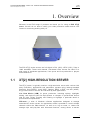
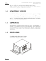
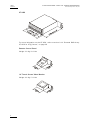
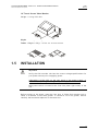
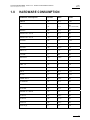
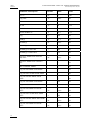


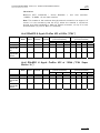

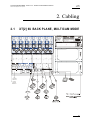
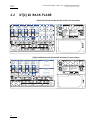
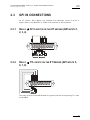
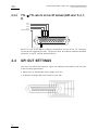


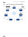
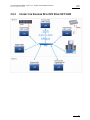

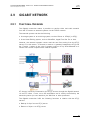
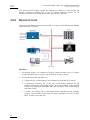
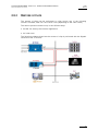


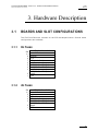
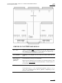


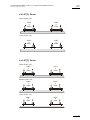
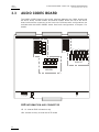


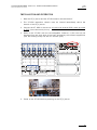


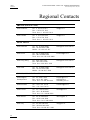


![2.8 conexión de varios servidores xt[2]](http://vs1.manualzilla.com/store/data/006305919_1-9948e093384d4040cdf0f68f445b7f43-150x150.png)


![XL[2] Technical Reference – Hardware](http://vs1.manualzilla.com/store/data/005956150_2-4515f3a1b925b4223206cf04092ab5bd-150x150.png)