1
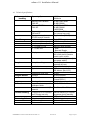
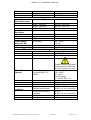
R Installation Manual Version 3.0 29-Sep-2009 04906900001 INSTALLATION-MANUAL cobas c 111 Last printed: 7 January 2010 Page 1 of 43 cobas c 111 Installation Manual This page has been left empty intentionally 04906900001 INSTALLATION-MANUAL cobas c 111 Version 3.0 Page 2 of 43 cobas c 111 Installation Manual CONTENT: 1. Preface ......................................................................................................................4 1.1 Revision history ...............................................................................................4 1.2 Copyrights and trademarks.............................................................................4 1.3 Manufacturer ...................................................................................................5 1.4 Intended use.....................................................................................................5 2. About this manual ...................................................................................................6 2.1 Conventions used in this manual ...................................................................6 2.1.1 Symbol listing ..............................................................................................6 2.1.2 Abbreviations...............................................................................................6 Units .....................................................................................................................6 Acronyms .............................................................................................................7 3. Safety information...................................................................................................7 3.1 Safety classifications.........................................................................................7 3.2 Safety notices....................................................................................................7 4. Overview.................................................................................................................11 4.1 Introduction...................................................................................................11 4.2 Instrument internal layout............................................................................12 4.3 Technical specifications.................................................................................13 5. Delivery, unpacking and set-up of the analyzer ..................................................16 5.1 Delivery ..........................................................................................................16 5.1.1 Packing list .................................................................................................16 5.2 Additional items required .............................................................................16 5.3 Unpacking......................................................................................................17 5.3.1 Unpacking procedure for instrument with ISE: ......................................17 5.3.2 Unpacking procedure for instrument without ISE: ................................19 5.4 Location of switches and connectors............................................................21 Main switch........................................................................................................21 Power cable ........................................................................................................21 Location of fuses ................................................................................................21 Fluid Connections:.............................................................................................21 USB connection .................................................................................................21 RS232 Serial connectors ....................................................................................22 6. Start-up of the Instrument....................................................................................23 6.1 Instrument with ISE unit ..............................................................................23 6.1.1 Instrument placement & preparation: .....................................................23 6.1.2 Starting the instrument & setup of ISE ....................................................23 6.2 Instrument without ISE unit.........................................................................26 6.2.1 Instrument placement & preparation: .....................................................26 6.2.2 Starting the instrument .............................................................................27 6.3 Single ISE unit................................................................................................29 6.3.1 Attaching the ISE unit to the base instrument (if applicable) ................29 7. Running the analyzer and everyday tasks............................................................34 8. Shutting down........................................................................................................34 9. Preparing for transportation ................................................................................34 9.1 Drain the instrument with ISE of water and cleaner. ..................................34 9.2 Drain the instrument without ISE of water and cleaner. ............................34 9.3 Packing procedure for instrument with ISE:................................................35 9.4 Packing procedure for instrument without ISE:..........................................39 10. Disposal of the instrument ...................................................................................42 10.1 Disposal of external components..................................................................42 11. Installation Report Form ......................................................................................42 12. Installation Report cobas c 111 ............................................................................43 04906900001 INSTALLATION-MANUAL cobas c 111 Version 3.0 Page 3 of 43 cobas c 111 Installation Manual 1. Preface 1.1 Revision history Version 0.1 0.2 0.5 0.9 1.0 1.1 1.2 1.3 1.4 2.0 2.1 2.2 Revision date May 2005 June 2005 January 2006 May 2006 June 2006 July 2006 August 2006 March 2007 October 2007 April 2008 Sep 2008 April 2009 3.0 September 2009 Document Part Number Comments Draft version Improved draft Improved draft 2 Improved draft 3 First release version Corrected version (procedure) Regulatory corrections Update of procedures Update of procedures Update of procedure for deinstallation ISE Update of instrument placement & prep. New transport protection Installation procedure ISE adjusted Generally remarks concerning Data base and applications added (empty Database) 04906900001 Published by Roche Diagnostics, a division of F. Hoffmann-La Roche; 4070 Basel, Switzerland. Questions or comments regarding the contents of this Manual can be directed to the address below or to your Roche representative. Roche Diagnostics Ltd. Global Systems Support Forrenstrasse CH- 6343 Rotkreuz Switzerland Every effort has been made to ensure that all the information contained in the cobas c 111 Installation Manual is correct at the time of printing. However, Roche Diagnostic Ltd. reserves the right to make any changes necessary without notice as part of ongoing product development. 1.2 Copyrights and trademarks cobas c 111, and the R® logo are registered trademarks of F. Hoffmann- La Roche Ltd. Canada: The above trademarks are owned by Roche Diagnostic Systems, a division of HoffmannLaRoche Limited/Limitee; used under License. Other countries: The above trademarks are either owned by or used under license by the Roche affiliate distributing this product. 04906900001 INSTALLATION-MANUAL cobas c 111 Version 3.0 Page 4 of 43 cobas c 111 Installation Manual The following trademarks are acknowledged: Adobe Acrobat, Linux, Microsoft Windows. 2008, F. Hoffmann- La Roche Ltd. All rights reserved. 1.3 Manufacturer Manufacturer Roche Diagnostics Ltd. Forrenstrasse CH-6343 Rotkreuz Switzerland 1.4 Intended use The cobas c 111 instrument is a continuous random-access analyzer intended for the invitro determination of clinical chemistry and electrolyte parameters in serum, plasma, urine or whole blood. (Only HbA1c application) It is important that the operators read this manual thoroughly before using the system. Any disregard of the instructions in this or the Operator’s Manual may result in a safety risk. 04906900001 INSTALLATION-MANUAL cobas c 111 Version 3.0 Page 5 of 43 cobas c 111 Installation Manual 2. About this manual This manual is to be used for unpacking, installing and registering the cobas c 111. For detailed instrument information, see the cobas c 111 Operator’s Manual. 2.1 Conventions used in this manual The conventions used in this manual are as follows: 1., 2., 3., represents sequential steps in a procedure. You should follow these steps in order. 2.1.1 Symbol listing Caution: Refer to accompanying documents. Manufacturer of device These symbols are provided on the type plate of the instrument Electrical and electronic equipment marked with this symbol are covered by the European directive WEEE. The symbol denotes that the equipment must not be disposed of in the municipal waste system. (WEEE = Directive 2002/96/EC of the European Parliament and the council of 27 January 2003 on waste electrical and electronic equipment.) 2.1.2 Abbreviations The following abbreviations are used: Units cm in Ib psi VA VAC MΩ Centimeters Inches Pounds (weight) Pounds per square inch Volt- Amperes Volts (alternating current) Megohm (106 ohms) 04906900001 INSTALLATION-MANUAL cobas c 111 Version 3.0 Page 6 of 43 cobas c 111 Installation Manual Acronyms UL IEC CSA LED CB FCC EN Underwriters Laboratories Inc. International Electro technical Commission Canadian Standard Association Light emitting diode Certification body Federal Communications Commission European Norm 3. Safety information Before operating the cobas c 111, it is essential that you read and understand the safety information listed here. 3.1 Safety classifications The safety precautions and important user notes are classified according to ANSI Z535 resp. ISO 3864 standards. You must familiarize yourself with following signs and their meanings: Indicates a direct danger that, if not avoided, may result in death or serious injury. Indicates a possibly hazardous situation that, if not avoided, may result in death or serious injury. Indicates a possibly hazardous situation that, if not avoided, may result in slight or minor injury or may result in damage to equipment. Danger Warning Caution General warning symbol on the analyzer The triangular warning symbol on the analyzer is a general reminder that users should read the safety information contained in this manual. Users must be able to identify specific hazards and take appropriate action to avoid them. 3.2 Safety notices Read the Roche Diagnostics safety notices carefully and make sure you understand them. This information should be made available to new employees and kept for future reference. 04906900001 INSTALLATION-MANUAL cobas c 111 Version 3.0 Page 7 of 43 cobas c 111 Installation Manual Electrical safety Danger of electric shock. Keep the side panels closed while the analyzer is connected to the main power supply! The cobas c 111 is designed in accordance with safety standard EN/IEC 61010-1. Grounding of the instrument and those surfaces the user can come into contact with is provided by a grounded cable in accordance with protection class 1 (IEC). Users should not perform any servicing except as specifically stated in the cobas c 111 Operator’s Manual. Danger Biological safety Liquid waste and cuvette waste are potentially biological hazardous. Always wear gloves when handling those materials. Do not touch parts of the analyzer other than those specified. If sample is spilled on the analyzer, wipe up immediately and apply disinfectant. Consult your laboratory protocol for handling biohazard materials. Software virus warning Warning Roche does not provide any anti-virus Software. Therefore, it is essential to take precautions to ensure that any software loaded onto the system is virus-free. Do not load any software that is not approved by Roche Diagnostics! Recommendations Check any data carrier (e.g. USB memory stick) with an anti-virus program (on another computer) to ensure that they are virus free before using them on the cobas c 111. Optical Safety Warning Loss of sight! The intense light of the LEDs may severely damage your eyes. Do not stare into the LEDs! Scanning equipment using LED technology is covered by the international standard IEC 60825-1 LED safety: Class 1 Instrument Service & Maintenance The cobas c 111 is an electromechanical device that has no internal electrical parts serviceable by the user. For preventive maintenance, contact your Roche Service representative who is trained and qualified to perform the necessary maintenance. Any unauthorized modification to the system shall render the warranty or service agreement null and void. User safety Read the following list to familiarize yourself with the potential hazards and the precautions for operating the cobas c 111. 04906900001 INSTALLATION-MANUAL cobas c 111 Version 3.0 Page 8 of 43 cobas c 111 Installation Manual Electrical safety Danger of electric shock if you touch any power supply parts. Do not access any electrical parts while the analyzer is connected to the main power supply. Users may replace fuses if they follow the procedures described in this manual. Any other electrical modification is not allowed and may render any warranties on the cobas c 111 null and void. Fire risk Danger of explosion through sparks. Keep all potentially flammable or explosive material (for example, anesthetic gas) away from the analyzer. Spraying liquid on the power supply parts can cause a short circuit and result in a fire. Keep the cover closed while the analyzer is connected to the main power supply and do not use sprays in the vicinity of the cobas c 111. During fire-fighting operations disconnect the cobas c 111 from the main power supply. Analyzer in use Danger of hands injury by moving parts. Keep all covers closed during initialization or operation. Samples Danger from infectious sample material can cause severe illness. Avoid direct contact with sample material. Clean contaminated surfaces immediately and dispose of waste according to local regulations. Please refer to your local safety regulations regarding handling sample material. Waste Danger from infectious waste material can cause severe illness. Avoid direct contact with waste. Dispose of the waste according to local regulations. Quality control Danger of false results. Patients can be put at risk if false results lead to incorrect diagnosis and therapy. Carry out quality controls according to the local regulations. Correct use Use the cobas c 111 only for measuring liquid sample material with the specified Roche reagents. Sample material can be serum, plasma, urine. User qualification Danger from incorrect operation. The cobas c 111 should only be used by a qualified operator experienced in the use of such equipment. Environmental conditions Incorrect location can cause incorrect results and damage to the equipment parts. Follow the installation instructions carefully. Moving the cobas c 111 must be performed only by qualified personnel. Location The cobas c 111 is designed for indoor use and the instrument must be located on a stable and level surface that is not subject to vibration. The instrument should not be placed in a position where strong or variable light conditions exist (e.g. direct sunlight). Avoid locations where other equipment may create interference from high frequency or high voltage electromagnetic fields. Allow sufficient space around the instrument for convenient working. 04906900001 INSTALLATION-MANUAL cobas c 111 Version 3.0 Page 9 of 43 cobas c 111 Installation Manual Environmental conditions The cobas c 111 is designed to operate in a controlled environment. In particular the room temperature, relative humidity and atmospheric pollution conditions must be maintained within the limits specified above (par. 4.3). Operation outside of the specified ranges may cause erratic operation or, in exceptional circumstances, component failure. Protective grounding The protective grounding is done via the mains power cord. There are no special provisions for protective grounding required. Warning Any break in the electrical ground wire, whether inside or outside the analyzer, or disconnection of the electrical ground connection, may create a hazardous condition. Under no circumstances should the user attempt to modify or deliberately override the safety features of this system. Risk of infection from contaminated samples! Fluid and cuvette waste is potentially biologically hazardous. Samples containing material of human origin must be treated as potentially infectious. Always wear protective gloves when handling this material. Do not touch parts of the analyzer other than those specified. The whole inside of the system may be contaminated with potentially infectious or toxic material. Always wear protective gloves when cleaning the following parts: Waste area, Sample Area, Pipetting System e.g., probes, Battery may explode if mistreated! Do not recharge, disassemble or dispose of the battery in fire. Servicing of the battery circuit and replacement of the lithium battery must not be done by the user. Only authorized persons are allowed to replace the lithium battery. Replace Battery with type Sonnenschein SL-360/S only. Use of another battery may present a risk of fire or explosion. User maintenance actions and internal cleaning All internal cleaning must be performed according to the instructions given in the cobas c 111 Operator’s Manual. Danger of damaging the Touch-Screen Display Excessive use of liquid cleaner may damage the Touch-Screen display! Do not spray any cleaner liquid directly onto the screen! Please clean the surface of the monitor with a cloth that is moistened with cleaner liquid. 04906900001 INSTALLATION-MANUAL cobas c 111 Version 3.0 Page 10 of 43 cobas c 111 Installation Manual 4. Overview 4.1 Introduction The cobas c 111 analyzer is intended for in vitro quantitative or qualitative determination of a wide range of analytes in serum, plasma and urine. (Whole blood only with HbA1c application.) The cobas c 111 is intended for professional use only. The primary functions of the cobas c 111 analyzer include: • • • • • • • • • • • Manual loading of various primary and secondary sample tubes onto the instrument providing 8 positions. Sample volume per test from 2 ... 15 µl Manual and/or computer-interfaced test ordering Cooled storage area for Roche reagents. 27 reagent bottles per reagent disk and up to 8 reagent disks can be handled. Using reagents manufactured by Roche Diagnostics ensures best quality of stable and reliable results. Bar-coded reagent bottles for easy handling. Absorbance Photometry measurements with 12 wavelengths ranging from 340 nm up to 659 nm Ion Selective Electrode (ISE) measurements for Na, K, and Cl, using the indirect method. Dilution of the sample 1:6. Result memory can keep up to 300 patient results. Optional formats for data interchange via RS-232 (ASTM-protocol) Sample identification with handheld barcode scanner Internal thermal printer (112 mm paper width) 04906900001 INSTALLATION-MANUAL cobas c 111 Version 3.0 Page 11 of 43 cobas c 111 Installation Manual 4.2 Instrument internal layout The major components of the analyzer are shown below in fig 1. 04906900001 INSTALLATION-MANUAL cobas c 111 Version 3.0 Page 12 of 43 cobas c 111 Installation Manual 4.3 Technical specifications Software and data Operating System handling Memory DM- Module PXA 255 Memory RT-CPU PXA 255 Mass Storage Communication between DM and RT Communication between RT-CPU and µC boards internal external (data share) Interfaces (external) 2 x USB 1.1/2.0 2 x RS-232 Display Printer Samples Sample handling Incubation time Typical time to result Reagent bottles Calibration Cuvette handling Measuring Unit Instrument cycle time Content Identification Number of tests Use of Roche test-specific calibrator fluids Use of recommended QC material 6 segments of 10 cuvettes each. Single use only Incubation Temperature Absorbance photometer 12 Wavelengths Sensor 04906900001 INSTALLATION-MANUAL cobas c 111 LINUX VX Works 32 MB Flash ROM 32 MB DRAM 32 MB Flash ROM 32 MB DRAM 2 MB SRAM 10/100 BaseT Ethernet (for internal use only) TegiLink Bus (RS485) Flash ROM USB Memory Stick Memory stick, Modem - Host - Barcode Reader 5.7 in. color LCD, (¼ VGA 320 x 240 pixels); passive matrix touch screen. Internal thermal printer (112 mm paper width) Direct tube placement manually by user Max. 12 min. / 40 cycles ABS: 4 min. to 12 min. ISE: 90 sec. (Na, K, Cl) 18 sec. 20 ml maximum Barcode 2-d, Format PDF417 50-200 depending of test CFAS, ISE Calibrator, etc. PreciNorm, PreciPath, etc. Manual handling of cuvette segments during standby. 37°C ± 0.2°C 20 W halogen lamp 340 nm ... 659 nm Photosensitive diode array Version 3.0 Page 13 of 43 cobas c 111 Installation Manual ISE Ion-Selective Electrode Sample volume OMNI©-Style Electrodes Indirect measurement 15 µl (Dilution 1:6) Na, K, Cl, Reference Physical dimensions (max.) Width /(with ISE) 590 mm / (720 mm) Depth / (with ISE) Height / (with ISE) Weight / (with ISE) Width 550 mm / (550 mm) 480 mm / (480 mm) 32 kg (35 kg) 850 mm Packing dimensions Depth Height Weight Line voltage 700 mm 850 mm 58 kg 100 – 250 V~ Power require4 A max. ments w/o ISE Line frequency 47 – 63 Hz Power consumption 250 VA This unit must be connected connected to a grounded mains outlet! Insulation coordination Category II (IEC 61010-1) Main Fuse T6.3A H 250V Secondary Fuses (4x) T3.15A 250V Battery ISE unit Data (Option) Environmental conditions External Power Supply UL-listed QQGQ/7 or EPBU/7 Weight Insulation coordination Power consumption Temperature/Humidity Transport and Storage Temperature/Humidity Operating Pollution Altitude 04906900001 INSTALLATION-MANUAL cobas c 111 Replace Battery with type Sonnenschein SL360 only Not to be replaced by user! Input Voltage: 100 – 240 V~ 50 - 60 Hz Output Voltage: 19 – 24 Vdc, Min. 4 A 3 kg Category II (IEC 61010-1) 70 VA max. -25 °C to 60 °C 10-95% rH, non condensing 15-32°C, 30-80% rH, non condensing Degree 2 (IEC 61010-1) 2000m above sea level Version 3.0 Page 14 of 43 cobas c 111 Installation Manual Safety approval UL 61010-1 EN/IEC 61010-1 EN/IEC 61010-2-101 CAN/CSA C22.2 No. 61010-1 Regulatory compliance CE: Complies with European Union (EU) Directive 98/79/EC (in vitro medical device) FCC: This equipment complies with the requirement in part 15 of FCC rules for a class A computing device. Operation of this equipment in a residential area may cause unacceptable interference to radio and TV reception requiring the operator to take whatever steps are necessary to correct the interference. Underwriters’ Laboratories (USA) International Electro technical Commission UL IEC 04906900001 INSTALLATION-MANUAL cobas c 111 Version 3.0 Page 15 of 43 cobas c 111 Installation Manual 5. Delivery, unpacking and set-up of the analyzer This section describes the state of the analyzer on delivery, how to unpack and set-up the instrument. The installation and set-up, however, must be performed by a certified person. Please ask your local representative if you have any questions regarding the installation. 5.1 Delivery The cobas c 111 analyzer is shipped in a specially designed container. On delivery, carefully inspect the container. Make a note of any indications of physical damage and record your observations in the accompanying shipping documents. It is essential that you report any suspected damage immediately to Roche Diagnostics, and to the shipping agent, before accepting the unit. Please also note the Installation Report Feedback Form at the end of this document. 5.1.1 Packing list The actual version of the analyzer (as delivered), together with a list of the accessories for your configuration, are detailed in the accompanying packing list. That list specifies the part numbers and quantities supplied. Please check the items supplied against the packing list and retain the list for future reference. 5.2 Additional items required To be able to install and set up the cobas c 111 correctly it is necessary to provide the following additional items: Power supply cord, either: US-Type: Cable Power Mains US STD: No. 25565608001 (rated 15A, 125V. Cable SJT, 3x16 AWG. Connector type 13V (10A, 250V; 15A, 125V) or Euro-Type: Cable Power Mains, No. 25565607001 (3 x 1mm2) rated 10A, 250V, or equivalent. For other country specific power connectors equivalent conditions apply. See also the pictures 3 & 4 below. Operator Manual Ordering of additional material to operate the instrument like cuvette segments, reagents, calibrator material, QC material, suitable sample tubes, cleaner etc. Please contact your local sales representative for further details. 04906900001 INSTALLATION-MANUAL cobas c 111 Version 3.0 Page 16 of 43 cobas c 111 Installation Manual cobas c111 instrument connector ISE Unit Power Supply Connector 5.3 Unpacking Important: Do not allow unqualified personnel to unpack, set up, or perform first time operation of the cobas c 111. Unauthorized action taken by the customer in this regard could void the warranty on the analyzer. The original shipping containers must be transferred unopened to the installation site. Unpack the instrument and check that all items mentioned on the packing list are present. If the package is damaged or parts are missing please report immediately to your local Roche Diagnostics representative and file a report with the shipping agent. 5.3.1 Unpacking procedure for instrument with ISE: 1. Open the box at the top. (On the upper cardboard cover inside the box you can find the standard accessories of the system). Bottle rack Accessoires 04906900001 INSTALLATION-MANUAL cobas c 111 Version 3.0 Page 17 of 43 cobas c 111 Installation Manual 2. Remove the standard accessories. 3. Lift the carton off the pallet to get access to the instrument. 4. Remove the upper cardboard cover. 5. Remove the plastic transport protection covering the instrument. Remove 04906900001 INSTALLATION-MANUAL cobas c 111 Version 3.0 Page 18 of 43 cobas c 111 Installation Manual Lift the cobas c 111 instrument from the pallet. Caution: The instrument weighs around 38 kg (~80 lbs.) 6. Notice: Place the cobas c 111 on flat and stable surface. Keep the packing pieces in a safe place to use again whenever the instrument has to be transported any significant distance. 5.3.2 Unpacking procedure for instrument without ISE: 1. Open the box at the top. (On the upper cardboard cover inside the box you can the standard accessories of the system). Bottle rack Accessoires 2. Remove the standard accessories and the upper cardboard cover. 04906900001 INSTALLATION-MANUAL cobas c 111 Version 3.0 Page 19 of 43 cobas c 111 Installation Manual 3. Lift the carton off the pallet to get access to the instrument. 4. Remove the upper cardboard cover 5. Remove the plastic transport protection covering the instrument. Remove 1. Turn 2. Remove Plastic transport protection 6. Lift the cobas c 111 instrument from the pallet. Caution: The instrument weighs around 35 kg (~75 lbs.) Empty palette 04906900001 INSTALLATION-MANUAL cobas c 111 Version 3.0 Page 20 of 43 cobas c 111 Installation Manual 7. Notice: Place the cobas c 111 on flat and stable surface. Keep the packing pieces in a safe place to use again whenever the instrument has to be transported any significant distance. 5.4 Location of switches and connectors Locations and use of all the switches, fuses and connectors are listed here, (See also Fig. 2 below) Main switch The main switch is on the left side on top of the analyzer. Press 1 to switch on the analyzer, press 0 to switch it off. If an ISE unit is attached, the ISE power supply will be on as long as it is connected to a mains power outlet. The constant powering of the ISE unit is intended due to functional reasons. Caution Damage to electrodes and possible tubing blockage. Do not unplug or switch off the ISE Power Supply. Periodic flow of solutions must be given at all times. Power cable The power supply socket is located at the rear of the instrument. Important: Only use an approved power supply cord in good condition! Do not touch mains cables if your hands are wet. Warning Do not attempt to connect or disconnect the mains cables, if the analyzer is switched on. If any power connector becomes worn or frayed, it must be replaced immediately with an approved cable. Location of fuses The Mains power fuse is located at the rear of the instrument inside the power supply socket. The internal power supply fuses are accessible on rear right side of the instrument. The fuse for ISE unit is located inside and is to be replaced by authorized service engineers. Fluid Connections: On the right side of the instrument is the Fluid Connector Terminal. It holds the a) Water Connector; b) Waste Connector; c) Cleaner Tubing Connector. USB connection A USB connector is located at the right front side of the instrument, which is intended for connecting to a USB memory stick. Any USB memory device that supports the USB v1.1 standard can be used on this USB port. A USB connection exists at the rear right side of the instrument, which is intended for connecting an analog modem. 04906900001 INSTALLATION-MANUAL cobas c 111 Version 3.0 Page 21 of 43 cobas c 111 Installation Manual RS232 Serial connectors There are 2 serial interface connectors intended for use with a Barcode scanner and Host interface respectively. Please refer to the cobas c 111 Operator Manual and the corresponding instructions before attempting to connect up. cobas c 111 external connections 04906900001 INSTALLATION-MANUAL cobas c 111 Version 3.0 Page 22 of 43 cobas c 111 Installation Manual 6. Start-up of the Instrument 6.1 Instrument with ISE unit 6.1.1 Instrument placement & preparation: 1. 2. 3. Follow all steps of procedure 6.2.1 below (see Instrument without ISE Unit) Connect the ISE power supply cable into an appropriate AC wall socket. Follow all steps of procedure 6.1.2 below. 6.1.2 Starting the instrument & setup of ISE Notice: 1. 2. 3. 4. Before switching on the instrument, make sure that the Transfer Head can move smoothly, and all covers are closed properly. Switch on the instrument by pressing the mains power switch to “I” The instrument will perform an initialization and check all vital components. Please wait until the instrument will show the status “Standby”. Log in as admin Notice: 5. 7. 8. 9. Upon delivery, the instrument is drained of water, so eventually an error message “Air detected in the fluid system” will appear. Ignore it until you performed step 6. Otherwise you have to check the fluid tubing for leakages. Check the Reagent Disk. If there is none inside, please insert one. (The description on how to insert a Reagent Disk is found in the Operator’s Manual) Notice: 6. All operator-related instructions on how to handle the instruments during the following procedure are described in the Operator’s Manual. If there is a Reagent Disk inside, but is not detected by the software, then check for correct identification by the flags. Exactly one of these flags needs to be broken away for correct ID. Use the Diagnostic function “Fill and empty fluid system” to fill the fluid system. Watch closely the water and cleaner fluids flowing through the tubing. Remove the transfer head cover for this purpose. Use the Maintenance function “Deproteinize Probe” to activate the probe for correct pipetting. This process needs 2 “False bottom”-cups, (or any other suitable cup) one filled with 1.5 ml of ISE Deproteinizer, and one filled with 1 ml of Activator. Those tubes have to be prepared before starting this maintenance function. Follow the instructions given by the software, when and how to place these tubes. Check the correct setting of time and date. Perform ISE Applications Import and installation if not yet done. To do so, access to Utilities > Applications > Laboratory Parameters > select then Add Tab click ( + ). As next “Import Application” tab will be displayed and by clicking on it the System will ask for the BTS or for an upload using the USB Stick. After providing this information select the Add Tab again click ( + ) and click in Install Application. The installation will be performed. Once the installation is successfully done, the brackets which were surrounding the application name previously won’t be visible anymore. For example:[K] installation not yet done. ; K installation already done. 04906900001 INSTALLATION-MANUAL cobas c 111 Version 3.0 Page 23 of 43 cobas c 111 Installation Manual Notice: There will be no Applications which will be ready to install. All wanted Applications must be imported first (via BTS or USB Stick) to be ready to install them. With Software Version 3.0 and higher the database will be delivered empty. The only to Profiles which will be available are ISE-I and ISE –U. 10. Prepare the additional material required to run the ISE, like electrodes, calibrator indirect, reference solution, solution 1 and solution 2. 11. Check the correct placement of all pre-mounted ISE tubing. 12. Mount all ISE valve caps (and clamps if necessary). Do this using the diagnostic function “Check ISE valves”. Use this function to open the valves first, to avoid bending of the valve shafts. 13. Check that sample inlet tube is correctly mounted to the mixing tower holder inside the base instrument. 14. Read in the barcode from the Reference Fluid and Calibrator indirect bottle and place the bottles into the ISE module. Insert the respective tubing into the bottle. 15. Insert the reference electrode, using the system SW. At the step where it is requested to insert the electrode insert also all the other electrodes. Notice: Take care to avoid air bubbles in the electrolyte at the lower end of the electrode body. 16. Read in the barcodes of Na, K and CL (Dummy electrode) accordingly. 17. Check the electrodes, the valves and the tubing for correct placement. During the following step watch the valves to operate correctly. 18. Check if the peristaltic pump cover is closed. 19. Use the maintenance action “Prime ISE calibrator and reference” to prime the tubing. 20. Use the maintenance action “Initialize ISE reference sensor” to set the controller SW properly recognizing air bubbles in the reference tubing. (Please follow the procedure given by the SW). 21. Close all covers. 22. Use the maintenance action “Condition Tubing”. For this action you will need Activator prepared in a HHT-Cup. 23. Use the maintenance action “Initialize ISE” to initialize the ISE unit. This action needs Activator. 24. Selecting the ISE status button and the “>>”-Button, you will be guided to perform an “Electrode Service” now, which needs Activator, Etcher and Deproteinizer on board. 25. Read the barcode of the ISE Calibration Kit and install the desired ISE tests in the Applications Menu. 26. As a general function test run a single CHECK test first. For this purpose Import and install the CHECK test application and order a single test only, like as you would order any other test. Check that the result is within the range printed on the CHECK test solution bottle. Later on you may disable the CHECK test. Notice: The calibration result for the CHECK test that is stored in the database cannot be deleted, as it is always used as reference. 27. Reset Maintenance Counter: Please choose “Utilities -> Diagnostics -> Analyzer > Installation Completed” 28. Calibrate now all ISE tests. The calibrations must be flag free. 29. Prepare the requested reagent bottles and insert them into the instrument. 30. Prepare the calibrators and QC material accordingly and calibrate all tests. 31. Check the test performance by running controls. 04906900001 INSTALLATION-MANUAL cobas c 111 Version 3.0 Page 24 of 43 cobas c 111 Installation Manual 32. Complete the installation report form. Any factory-set calibration data found on the instrument may be outdated and therefore cause wrong results! Cross-check the calibration results and the application producing correct results by running qualified control material. Refer Warning to the cobas c 111 Operator’s Manual for more handling information. 04906900001 INSTALLATION-MANUAL cobas c 111 Version 3.0 Page 25 of 43 cobas c 111 Installation Manual 6.2 Instrument without ISE unit 6.2.1 Instrument placement & preparation: 1. 2. 3. 4. 5. 6. 7. Place the instrument in a suitable position for operation (refer to location and environmental conditions above). Unpack all accessory components like Water and Waste Reservoir, Reagent Disk, Barcode Scanner, Printer paper, etc. Preposition all additional parts as appropriate power cord, cuvettes, reagents, calibrators, etc. Insert a roll of printer paper as instructed in the Operator’s Manual. The printer paper (thermal paper) is heat-sensitive and must be kept away from direct sunlight and high temperatures. Mount the probe onto the Transfer Head. Place the Fluid Rack to the right side of the instrument. Place a new bottle of cleaner, fill the Water Container with de-ionized water (CLSI Grade II) and check that the Waste Container is empty. As next step Connect the Cleaner Protection pipe. Notice: Make sure the two internal Seals which are located in the interior of the black protection pipe were mounted previously as shown on the picture above. Attention: To avoid seals damaging, push pipe carefully to end position. Consider to grease previously both seals, to assure an easier operation. 8. 9. Mount the Fluid Water and Waste tubing sets to the respective lids. Connect the tubing connectors to their respective counterparts at the Fluid connector terminal at the right side of the instrument. 10. Place the lids on top of their bottles. White -> water; yellow -> waste; red -> cleaner. 11. Plug the cable of the barcode scanner into the COM2 port. (This is the port named with Scanner) 12. Connect the cross wired LAN cable to the RJ45 connectors (named DM and IC) 04906900001 INSTALLATION-MANUAL cobas c 111 Version 3.0 Page 26 of 43 cobas c 111 Installation Manual cobas c 111 external connections 13. Plug one end of the power connector cable into the power socket at the rear of the instrument and the other end into an appropriate AC wall socket. 6.2.2 Starting the instrument Notice: 1. 2. 3. 4. Before switching on the instrument, make sure that the Transfer Head can move smoothly and all covers are closed properly. Switch on the instrument by pressing the mains power switch to “I” The instrument will perform an initialization and check all vital components. Please wait until the instrument will show the status “Standby”. Log in as admin. Notice: 5. 7. As the instrument is drained of water when delivered, eventually an error message “Air detected in the fluid system” will appear. Ignore it until you performed step 6. Otherwise you have to check the fluid tubing for leaks. Check the Reagent Disk. If there is none inside, please insert one. Notice: 6. All operator-related instructions on how to handle the instruments during the following procedure are given in the Operator’s Manual. If there is a Reagent Disk inside, but is not detected by the software, then check for correct identification by the flags. Exactly one of these flags needs to be broken away for correct ID. Use the Diagnostic function “Fill and empty fluid system” to fill the fluid system. Watch closely the water and cleaner fluids flow through the tubing. Remove the transfer head cover for this purpose. Replace the cover afterwards Use the Maintenance function “Deproteinize Probe” to activate the probe for correct pipetting. This process needs 2 “False bottom”-cups, (or any other suitable cup) one filled with 1.5 ml of ISE Deproteinizer, and one filled with 1 ml of Activator. Those tubes have to be prepared before starting this maintenance 04906900001 INSTALLATION-MANUAL cobas c 111 Version 3.0 Page 27 of 43 cobas c 111 Installation Manual 8. 9. function. Follow the instructions given by the software, when and how to place these tubes. Check the correct setting of time and date. As a general function test run a single CHECK test first. For this purpose Import and Install the CHECK test application and order a single test only, like you would order any other test. Check that the result is within the range printed on the CHECK test solution bottle. Later you may disable the CHECK test. Please note: The calibration result for the CHECK test that is stored in the database can not be deleted, as it is always used as reference. 10. Reset Maintenance Counter: Please choose “Utilities -> Diagnostics -> Analyzer > Installation Completed” 11. Prepare the requested reagent bottles and insert them into the instrument. 12. Prepare the calibrators and QC material accordingly and calibrate all tests. 13. Check the test performance by running controls. 14. Complete the installation report form. Any factory-set calibration data found on the instrument may be outdated and therefore cause wrong results! Cross-check the calibration results and the application producing correct results by running qualified control material. Refer Warning to the cobas c 111 Operator’s Manual for more handling information. 04906900001 INSTALLATION-MANUAL cobas c 111 Version 3.0 Page 28 of 43 cobas c 111 Installation Manual 6.3 Single ISE unit 6.3.1 Attaching the ISE unit to the base instrument (if applicable) 1. 2. 3. 4. 5. Unpack the ISE unit and preposition all ISE accessory parts, like Electrodes, Calibrator indirect, Reference solution and Solution 1-2. Remove left and right side panel of the base instrument. Move the transfer head to the sample area and remove the left side panel and main cover. Remove the transfer head cover. Remove the screws on the left and right side that holds the rear service flap and fold it backwards. Fixation of rear panel 6. 7. Remove the complete ISE Cover and left side panel of the ISE unit. Route the flat ribbon cable from the instrument into the ISE. Route the ground strap from the ISE into the instrument. Route the waste tube from the ISE into the instrument (the end with the quick fit connector belongs into the ISE). 8. Fit the right side of the ISE unit to the left side of the instrument by inserting the rails into the guides. There are 2 screws that attach the ISE unit to the base instrument. Routing of ISE connections Notice: Take care not to squeeze the waste tube at any position! 04906900001 INSTALLATION-MANUAL cobas c 111 Version 3.0 Page 29 of 43 cobas c 111 Installation Manual ISE Module fixation screws 9. Connect the flat ribbon cable to the PCB ISE Controller J2. Flat ribbon cable connection 10. Remove the power box guard plate. Power box guard plate fixation 04906900001 INSTALLATION-MANUAL cobas c 111 Version 3.0 Page 30 of 43 cobas c 111 Installation Manual 11. Connect the ground strap using the provided screw and serrated lock washer. ISE ground strap fixation 12. Connect the waste tube to the corresponding plug. ISE waste connection 04906900001 INSTALLATION-MANUAL cobas c 111 Version 3.0 Page 31 of 43 cobas c 111 Installation Manual 13. Connect the low voltage end cable to the connector of the PCB ISE Control. Then fix the cable with the pull relief. ISE power supply 14. 15. 16. 17. Mount the power box guard plate back into place. Fold the Rear Service Flap into normal position and fix it with the 2 screws. Put the right side panel back into place. If not yet mounted fix the air tube to the mixtower socket. Mount the sample inlet tube to the socket. Mount now the socket to its location. ISE Mixtower socket fixation 18. Mount now the waste tube to the internal waste tank. Push the round black waste outlet into the tube holder until the stopper. Mount afterwards the cover back to the waste tank. Connection ISE waste to waste tank 04906900001 INSTALLATION-MANUAL cobas c 111 Version 3.0 Page 32 of 43 cobas c 111 Installation Manual Notice: Take care not to squeeze the waste tube at any position! 19. Mount the tube from the ISE tower overflow adaptor to the rear connector of the internal waste tank. Connection of overflow adaptor to waste tank 20. Finally mount the waste tube to ISE tower, mount the tower itself and lock the ring. Apply the overflow adapter at the end. Mounted ISE tower 21. Connect the ISE power supply cable into an appropriate AC wall socket. 22. Switch on the instrument 23. Follow now steps 9-27 of chapter 6.1.2 (Starting instrument & Setup of ISE) above. 04906900001 INSTALLATION-MANUAL cobas c 111 Version 3.0 Page 33 of 43 cobas c 111 Installation Manual 7. Running the analyzer and everyday tasks Refer to the cobas c 111 Operator’s Manual to see what tasks you must do each day before running tests and for information on day-to-day running of the analyzer. 8. Shutting down After completion of work the instrument should be allowed to enter the “Standby” status and the waste should then be emptied. You may use the “End of shift” wizard, guiding you through various procedures to prepare the instrument to be switched off for a longer time, e.g. overnight, weekend, etc. The instrument can then be switched off by the On/Off switch at the top left side. After switching off please ensure that the instrument is cleaned according to the instructions in the Operator Manual to avoid the build up of contamination. Another way to shutdown the instrument is to press the STOP button, then on the touch screen press “shutdown”. The instrument will shut down, after that switch off the instrument by the Power Switch 9. Preparing for transportation 9.1 Drain the instrument with ISE of water and cleaner. 1. Perform the Diagnostic function “Drain ISE Unit”, follow its instructions 2. Store the valve caps and clamps and the electrodes in separate bags at the place of the calibrator and reference bottles. 3. Now follow all the steps from procedure 9.2 below. Always use the approved packaging for transportation of the cobas c 111 analyzer. Before transporting or disposing of an instrument, carry out a Shutting down procedure and a full decontamination according to local regulations. 9.2 Drain the instrument without ISE of water and cleaner. 1. Remove the nozzle out of the external cleaner bottle and place on a paper tissue. Close the cleaner bottle and store it at a safe place. 2. Empty the water container. Leave it in place. 3. Perform the diagnostic action “Fill and empty fluid system”. 4. Empty the waste container. 5. Now the fluid tubing can be disconnected. 6. Remove all cuvette segments from the rotor. 7. Remove all reagents from disk, by using the System SW. 8. Remove the reagent disk from the instrument. Always use the approved packaging for transportation of the cobas c 111 analyzer. Before transporting or disposing of an instrument, carry out a Shutting down procedure and a full decontamination according to local regulations. 04906900001 INSTALLATION-MANUAL cobas c 111 Version 3.0 Page 34 of 43 cobas c 111 Installation Manual 9.3 Packing procedure for instrument with ISE: Notice: Use only the original packing pieces to prevent any damage of the instrument. The packing instructions are also shown on a label outside of the box Notice: Packing instruction 1. Start with preparing the palette. Empty palette 04906900001 INSTALLATION-MANUAL cobas c 111 Version 3.0 Page 35 of 43 cobas c 111 Installation Manual 2. Lift the cobas c 111 instrument and place it into the cellular material Caution: The instrument weighs around 38 kg (~80 lbs.) Palette with C111 instrument 3. Apply the protection plastic foil and the plastic bag over the transfer head Instrument with protection foil 4. Set up the left and right protection pieces Instrument with protection plastic pieces 04906900001 INSTALLATION-MANUAL cobas c 111 Version 3.0 Page 36 of 43 cobas c 111 Installation Manual 5. Impose on the surrounding carton. Packed in surrounding carton 6. Put on the cardboard cover. Cardboard cover Applied Cardboard cover Make sure to have the transfer head protection correctly mounted Transfer head protection 04906900001 INSTALLATION-MANUAL cobas c 111 Version 3.0 Page 37 of 43 cobas c 111 Installation Manual 7. Pack the accessories in the box as shown and the fluid rack incl. remaining fluid bottles into the other box. Accessoires box Bottle rack Accessoires Packed accessories + fluid rack boxes 8. If the TIP-N-TELL indicator applied on the cardboard cover (iniside box) and outside are still ok, leave them, otherwise cancel the corresponding one with a pen (??). TIP-N-TELL (inside) 9. TIP-N-TELL (outside) If possible apply new straps as shown below, or apply cords. Finished packing with straps 04906900001 INSTALLATION-MANUAL cobas c 111 Version 3.0 Page 38 of 43 cobas c 111 Installation Manual 9.4 Packing procedure for instrument without ISE: Notice: Notice: Use only the original packing pieces to prevent any damage of the instrument. The packing instructions are also shown on a label outside of the box Packing instruction 1. Start with preparing the palette. Empty palette 2. Lift the cobas c 111 instrument and place it into the cellular material Caution: The instrument weighs around 35 kg (~75 lbs.) and mount the protection foil. Palette with C111 instrument and protection foil 04906900001 INSTALLATION-MANUAL cobas c 111 Version 3.0 Page 39 of 43 cobas c 111 Installation Manual 3. Apply the protection plastic foil and the plastic bag over the transfer head. Set up the left and right protection pieces (just turn the one on the left side by 180 degrees) Instrument with protection plastic pieces 4. Impose on the surrounding carton. Packed in surrounding carton 5. Put on the cardboard cover. Cardboard cover Imposed on Cardboard cover Make sure to have the transfer head protection correctly mounted Transfer head protection 04906900001 INSTALLATION-MANUAL cobas c 111 Version 3.0 Page 40 of 43 cobas c 111 Installation Manual 6. Pack the accessories in the box as shown and the fluid rack incl. remaining fluid bottles into the other box. Accessoires box Bottle rack Accessoires Packed accessories + fluid rack boxes 7. If the TIP-N-TELL applied on the cardboard cover (inside box) and outside are still ok, leave them, otherwise cancel the corresponding one with a pen. TIP-N-TELL (inside) 8. TIP-N-TELL (outside) If possible apply new straps as shown below or cords. Finished packing with straps 04906900001 INSTALLATION-MANUAL cobas c 111 Version 3.0 Page 41 of 43 cobas c 111 Installation Manual 10. Disposal of the instrument If the instrument is to be scrapped then all parts maybe disassembled according to the procedures in the service manual to allow separate disposal of differing materials according to local regulations. The instrument must be treated as biologically contaminatedhazardous waste. Final disposal must be organized in a way that does not endanger the waste handlers. As a rule, such equipment must be sterile before it is passed on for final disposal. For more information contact your Local Safety Officer. 10.1 Disposal of external components External components such as the scanner and the ISE power supply, which are marked with the crossed-out wheeled bin symbol, are covered by the European directive 2002/96/EC (WEEE) These items must be disposed of via designated collection facilities appointed by government or local authorities. (WEEE) Directive 2002/96/EC of the European Parliament and the Council of 27 January 2003 on waste electrical and electronic equipment For more information about disposal of your old products, contact your city office, waste disposal service or your Local Safety Officer. Constraint: It is left to the responsible laboratory organization to determine whether control unit components are contaminated or not. If contaminated, treat in the same way as the instrument. 11. Installation Report Form For Field Service Engineer: Your feedback is needed! Please fill in the Installation Report and send it back to the Customer Support Team by Fax: ++41 41 798 72 18 by Mail: Roche Diagnostics Ltd. GSS cobas c 111 Forrenstrasse CH-6343 Rotkreuz Switzerland by E-Mail: [email protected] 04906900001 INSTALLATION-MANUAL cobas c 111 Version 3.0 Page 42 of 43 cobas c 111 Installation Manual 12. Installation Report cobas c 111 Instrument Serial No. Installation Date: Country: City: Responsible FSE: Main Power Supply Voltage: Subject: Package Not OK. OK. Frequency: Comments: Accessories Chassis / Housing Robotic Transfer Fluid / Pipetting Internal Printer Analyzer Assembly Reagent Disk Power Supply Cooling Unit Display Unit Touch Screen ISE Unit (option) ISE Unit power supply (option) Host Interface Connection (option) Other comments or findings: 04906900001 INSTALLATION-MANUAL cobas c 111 Version 3.0 Page 43 of 43