1
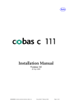
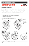
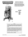
N51 , N52 EFM SHDSL.bis Modem
User’s Manual V1.2
NexComm Systems
Tel: +82-31-781-1862, Fax: +82-31-781-1863
E-mail: [email protected]
N50 Series User’s Manual
Copyright
Copyright © 2003-2004 NexComm Systems Co., Inc. All Rights Reserved.
This document contains information that is the property of NexComm Systems Co., Inc.
All or part of this document may not be copied, reproduced, reduced to any electronic medium or
machine readable form, or otherwise duplicated, and information herein may not be used,
disseminated or otherwise disclosed, except with the prior written consent of NexComm Systems
Co., Inc.
July 05, 2010
This document may be subject to change for correction and upgrade.
Contact
NexComm Systems Co., Inc.
C-501, Bundang Techno-Park,
145 Yatap-Dong, Bundang-Ku, Sungnam-City, Kyunggi-Do,
463-760, Korea
Tel: +82-31-781-1862
Fax: +82-31-781-1863
E-mail: [email protected]
Homepage: http://www.nexcomm.co.kr
NexComm Systems, Inc.
1 PAGE
N50 Series User’s Manual
Contents
PART I: N50 Series Introduction ................................................................................. 3
Introduction...................................................................................................................... 4
Specification .................................................................................................................... 5
Product appearance .......................................................................................................... 7
PART II: Installing N50 Series Modem ....................................................................... 9
Physical Environments................................................................................................... 10
Checking the box ........................................................................................................... 10
Connecting Cables and Connectors ............................................................................... 11
Mode Switch Configuration........................................................................................... 13
PART III: User Configuration Mode ......................................................................... 14
Before accessing the Web Setup Tool ............................................................................ 15
Using Web Setup Tool.................................................................................................... 17
Accessing the web site ............................................................................................. 17
Network Setup.......................................................................................................... 18
Statistics ................................................................................................................... 21
Password .................................................................................................................. 23
System Reboot ......................................................................................................... 24
Firmware Upgrade.................................................................................................... 24
Appendix...................................................................................................................... 27
Connector Pin-outs ........................................................................................................ 28
NexComm Systems, Inc.
2 PAGE
N50 Series User’s Manual
PART I: N50 Series Introduction
□ Overview and Features
□ Specification
□ Product appearance
NexComm Systems, Inc.
3 PAGE
N50 Series User’s Manual
Introduction
Introduction of N50 Series modem
Overview
N50 Series is a EFM SHDSL.bis bridge modem, which allows multiple PCs share a
high speed internet access. Based on ITU-T Standard (G.991.2) G..shdsl.bis 2004
technology provides symmetrical data rates of 384Kbps to 22.7Mbps with a range up to
7km using single pair of ordinary telephone wire.
It can be used as a Point-to-Point solution for LAN extension, or as a CPE (Customer
Premises Equipment) to the NexComm’s EFM SHDSL.bis Modem N554, N552, N5000,
or other vendors’ IP based DSLAMs or MSAN.
N50 Series can be configured as two types by simply setting parameters on HTTP server,
one for Master Unit which operates as Central Office Equipment and the other for Slave
Unit as a Customer Premises Equipment which doesn’t need to be configured at remote
site. The device is designed to be used both in offices and home environment.
Compactness in size and plug-and-play function feature ease-of-use.
Applications
Low-cost, entry-level EFM G.SHDSL.bis Customer Premises Equipment (CPE) modem
enables high-speed Symmetric DSL services
Broadband Internet Access Service application with DSLAMs
Point-to-Point connection for remote LAN extension
Features
TC-PAM encoded G..shdsl.bis
One WAN with up to two RJ-11 and one LAN with RJ-45
Supports 1 port of 10/100M Ethernet LAN of automatic sensing
Supports ITU-T G.991.2 (G.SHDSL.bis 2004) standard
Supports identical user data rates in both upstream and downstream directions
(symmetric technology) and vary from 384 Kbps:
- up to 11.4 Mbps in two-wire(one pair) mode
NexComm Systems, Inc.
4 PAGE
N50 Series User’s Manual
- up to 22.7Mbps in four-wire(two pair) mode
Support both Rate adaptive mode and fixed mode
Configurable via HTTP server
Plug and play when CPE mode operation
Specification
N50 Series has one 10/100M Ethernet port and one or two G..SHDSL.bis port.
[Table 1-1] N50 Series modem specification
Hardware Specifications
Memory
DRAM : 4Mbyte
Flash Memory : 512Kbyte
DSL Port (for G.SHDSL.bis)
1 port with RJ-11 , TC-PAM(G.991.2) -> N51
2 port with RJ-11 , TC-PAM(G.991.2) -> N52
LAN Port (for Ethernet)
1 port with RJ-45, Auto-MDI/MDIX
Data Rate
SHDSL.bis: 384Kbps~11,392kbps -> N51
SHDSL.bis: 768Kbps~22,784kbps -> N52
LAN: 10/100Mbps, auto-negotiation
Power
External Adapter
DC +5V 3A
Dimension
158mm(W) x 106mm(D) x 27mm(H)
Weight
0.3Kg
Software Specifications
Protocols
Bridging Transparent MAC Bridging,
2BASE-TL, 64/65o encoding
Management
CFG Mode Switch ( Round Robin )
HTTP Server (web based management)
NexComm Systems, Inc.
5 PAGE
N50 Series User’s Manual
Power Requirements
DC input voltage
+5V, 3A
F1, F2,F3,F4 : F1251T, 250 V, 2 A
Fuses
F3: 663, 250 V, 2 A
Power Adapter Requirements
This unit should use UL Listed AC/DC Adaptor, CCN: EPBU, EPBU7, QQGQ or QQGQ7 for
USA or Canada only. Marked with LPS or Limited Power Source for QQGQ or QQGQ7.
Rated input
100 VAC ~ 240 VAC, 0.3 A, 50/60 Hz
Rated output
5V DC, 3.0 A
NexComm Systems, Inc.
6 PAGE
N50 Series User’s Manual
Product appearance
The front side of N50 Series modem
N50 Series modem has various LEDs in front panel. LEDs in the front side of N50 Series modem
show each port status.
[Figure 1-1] Front side of the N50 Series
[Table 1-2] Status of LEDs
LED
STATUS
PWR
ON
Green ON
OFF
Power ON status
COE Mode status
CPE Mode status
Orange ON
Management Mode status
DSL port G.SHDSL sync at the Speed higher than
2320Kbps.
DSL port G.SHDSL sync at the Speed lower than
2320Kbps.
COE
DESCRIPTION
ON
SPEED
OFF
LINE0
ON
LINE0 G.SHDSL port sync up Æ N51 & N52
LINE1
ON
LINE1 G.SHDSL port sync up Æ N52 only
LINK/RX
ON/Blink
TX
Blink
LAN port Link / Data receiving
LAN port data transmitting
The rear side for N50 Series modem
N50 Series modem provides power, LAN and G..shdsl.bis connectors in the rear side.
NexComm Systems, Inc.
DC5V
LAN
LINE0
LINE1
[Figure 1-2] Rear side of the N50 Series
7 PAGE
N50 Series User’s Manual
[Table 1-3] The table below describes each port
Port
Explanation
DC5V
Connect to a DC 5V power adapter (an external 5V 3A adapter).
LAN
(RJ-45)
Connect to a UTP cable for communication with network devices such
as user's computer, hub, switch, and router.
LINE0
(RJ-11)
LINE1
(RJ-11)
NexComm Systems, Inc.
Connect a pair of copper wires for G.shdsl communication, i.e., connect
to the 3rd and 4th pins of the RJ-11 jack (6pin connector).
Æ N51 & N52
Connect a pair of copper wires for G.shdsl communication, i.e., connect
to the 3rd and 4th pins of the RJ-11 jack (6pin connector).
Æ N52 Only
8 PAGE
N50 Series User’s Manual
PART II: Installing N50 Series Modem
□ Physical Environments
□ Checking in the box
□ Connecting Cables and Connectors
NexComm Systems, Inc.
9 PAGE
N50 Series User’s Manual
Physical Environments
To install and operate N50 Series modem safely, a required range of the temperature and humidity
has to be kept.
The conditions of physical environment are as follows:
- Operating Temperature: 0º to 50ºC (32º to 122ºF)
- Storage Temperature: -20º to 70ºC (-4º to 158ºF)
- Relative Humidity: 5% ~ 95% (when there is no moisture condensing)
- Caution: No Fire
Checking the box
Following items are needed for the set up of N50 Series modem.
-
Power cable and a AC/DC adapter
-
UTP cable with RJ-45 connector for LAN connection
-
DSL cable with RJ-11(use 3rd and 4th pin) for SHDSL.bis connection
N50 Series box should contain the following components. Please be sure to check whether the
following items are in the box.
[Table 2-1] In a package of the N5x Series modem following items should be found:
Part’s Name
Amount
Main unit
1
The modem’s main unit
Power Cable
1
A cable that supplies power to the modem
Power Adapter
1
AC/DC adapter (DC 5V, 3A)
UTP Cable
1
For a Local Area Network (LAN) connection
DSL Cable
1
For a SHDSL.bis connection
Documentation
1
User Manual CD
NexComm Systems, Inc.
Usage
10 PAGE
N50 Series User’s Manual
Connecting Cables and Connectors
This part explains the physical set up for N50 Series modem. Connect the cable after checking the
ports in the rear side of N50 Series modem.
[Figure 2-1] This figure illustrates various hardware connections.
Wall Jack
DC5V
LAN
LINE0
LINE1
DSL cable
with RJ-11
DSL cable
with RJ-11
AC/DC
Adapter
Or
Straight-through cable or
Crossover cable
Stand-alone Computer
Step1>
Hub/Switch
(for local area network)
Locate N50 Series in a place where all of its cables can reach it, and where ventilation is
well done so that the air can flow freely through the air holes in the bottom of the unit.
Step2>
Connect the one end of the RJ-45 modular cable to the Ethernet port on your computer
or an Ethernet hub/switch port. Connect the other end of the cable to the LAN port at
the rear of N50 Series Modem.
Note: The LAN port is auto-MDI/MDIX capable; The LAN port will automatically
detect the Ethernet cable type being used (straight-through or crossover) and adjust to
make a link.
NexComm Systems, Inc.
11 PAGE
N50 Series User’s Manual
To reduce the risk of fire, use only No. 26 AWG or larger telecommunication
CAUTION
line cord.
Step3>
Plug the RJ-11 connector (to be connected to the 3rd and 4th pins, in case of 6 pins)
into a pair of regular telephone lines preinstalled for the SHDSL.bis connection and,
use a specific tool to achieve a connection properly. And connect the assembled RJ-11
connector to the port named LINE0 or LINE1 in the back of N50 Series unit.
Never connect the LINE0, LINE1 port directly to an external telephone line.
CAUTION
Step4>
You can set device-type (COE or CPE or MGT) and data rate by configuring the Mode
switches at the Front panel of N50 Series. To configure the Mode switches, refer to
Mode Switch Configuration Round Robin (page 13) table.
Note: Whenever you change Mode switches, you must reboot the modem after the
change.
Step5>
Plug one end of the power cable into the AC socket and connect the other end into the
DC adapter. Plug the DC cord of the power adapter to the DC 5V connector at the rear
of N50 Series Modem.
Step6>
Check the LEDs in the front panel.
1> Confirm if the LED named PWR is turned on among the LEDs in the front panel.
Note: If the LED is not on, check if the power cable is properly connected or if the
power terminal is being supplied with the normal power.
2> After power is on, check the LINK LED for the LAN is on.
Note: If the LED is not on, check to see if the UTP cable is properly connected, if there
is a disconnection in the UTP cable or if the RJ-45 jack is properly plugged in.
3> After LINK LED is on, check the LINE0,LINE1 LED is on. If both LEDs are on,
now it is ready for data communication.
NexComm Systems, Inc.
12 PAGE
N50 Series User’s Manual
Mode Switch Configuration
The following table explains MODE switch 3 sec time select configuration.
Mode Switch
(3 sec select)
Round Robin
Future
COE LED
Status
COE
ON
CPE
OFF
MGT
Orange ON
NexComm Systems, Inc.
COE Mode
- LAN/WAN IP: unnumbered
- LAN (promiscuous mode)
CPE Mode
- LAN/WAN IP: unnumbered
- LAN (promiscuous mode)
Magement Mode
- Accessing Web Setup Tool
- operates as user configuration mode
13 PAGE
N50 Series User’s Manual
PART III: User Configuration Mode
□ Before accessing the Web Setup Tool
□ Using Web Setup Tool
NexComm Systems, Inc.
14 PAGE
N50 Series User’s Manual
Before accessing the Web Setup Tool
You can configure all the setting of N50 Series by using the Web Setup Tool. To access the Web
Setup Tool, you must take the following steps in advance.
1> Configuring an IP address on your PC.
2> Connect the LAN port and your network device such as PC or Hub/Switch.
Configuring TCP/IP on your computer
To gain an access to N50 series Modem from a PC through TCP/IP connection, the PC
should satisfy the following requirements.
1> Hardware and OS Requirements
PC
System
Software
Windows 2000 or Higher
Network
Software
TCP/IP
Network
Hardware
Ethernet card
(10BASE-T or 100BASE-Tx)
NexComm Systems, Inc.
15 PAGE
N50 Series User’s Manual
2> Configuring TCP/IP on Windows
To set up TCP/IP configuration on Windows environments, the following procedure
should be performed in advance.
☞ Check the user's computer hardware.
√Make sure that the Ethernet card (Network Adapter) is installed.
√Make sure that the Ethernet card supports the TCP/IP protocol.
☞ Confirm if TCP/IP has already been installed in the computer running on Windows.
The confirmation can be done with the following steps: [Start] →[Setup]
→[Control Panel] →[Network] →[Network Configuration]. If the item TCP/IP is
not found, use Windows Setup CD and install it.
3> Assigning an IP address to your computer
If both hardware and software were already installed for the network services IP address
that was assigned to the host has to be configured.
① [Start] →[Setup] →[Control Panel] →[Network] →[Network Configuration]
② Select TCP/IP in the list and then select the Registration Information tap. If TCP/IP
Registration Information is displayed in the screen, select the IP Address tap.
Click “Use Assigned IP Address” and then enter the assigned IP address and subnet
mask. Enter ‘192.168.1.1’ in the IP Address field and Enter ‘255.255.255.0’ in the
Subnet Mask field.
[Figure3-1] Assigning an IP Address
③ Click the [OK] button in the current window. In the next window, click the [OK]
button to activate and the computer is going to reboot of the computer at once.
NexComm Systems, Inc.
16 PAGE
N50 Series User’s Manual
Using Web Setup Tool
HTTP server application resides on the N50 series Modem itself. This enables an administrator to
manage and configure the system via Graphical User Interface, using an HTTP-compliant Web
browser.
You can access the web site of N50 series Modem from any computer on the same Ethernet
network as the N50 series Modem.
Accessing the web site
Step1> Once you establish the IP address and have network connectivity, you can enter
the IP address of the N50 series Modem in the URL box on your browser. And press
<Enter>. The default IP address is ‘192.168.1.254’. This is a predefined IP address for
the LAN port on your N50 series Modem .
[Figure3-2] The URL box
Step2> You will then be asked for a User name and Password. Enter your password and
then click [OK] button.
[Figure3-3] The log-in page displays as follows:
NexComm Systems, Inc.
17 PAGE
N50 Series User’s Manual
If you launch the web setup tool for the first time, enter ‘password’ by default. The User
Name is to be ignored. The N50 checks only password.
Step3> If your password is right, the Network Setup page displays.
[Figure3-4] Network Setup page
Network Setup
Use Network Setup menu to configure the N50 Series Modem.
To configure your device, click Network Setup menu at the left frame. The Network
Setup page displays as shown in the Figure3-5. You can configure a hostname, an IP
address, G.SHDSL ports and SNMP agent in this page.
NexComm Systems, Inc.
18 PAGE
N50 Series User’s Manual
[Figure3-5] Network Setup page
This page contains the following command buttons.
Use the following buttons to enter or cancel your changes.
Submit
-
Takes effect and stores in flash memory any changes you have made on the current
page.
Reset
-
Revert all edited fields to the values originally contained as long as a [Submit] was
not performed.
This page contains the following fields.
HOSTNAME
Configuring a hostname for your N51 or N52.
NexComm Systems, Inc.
19 PAGE
N50 Series User’s Manual
LAN
Configuring an IP address and a default gateway for your N50 series Modem .
IP Address
Enter an IP address for the LAN port.
Netmask
Enter an IP subnet Mask.
Default Gateway
Enter your default gateway’s IP address.
To access the N50 on remote network, you must set up a
default gateway.
WAN
The WAN interface supports multiple data rate and rate-adaptive capability. Also it can
act as both a COE and a CPE. The SHDSL port supports a variety of line rates ranging
from 384kbps to 22784kbps. In rate adaptive mode line rate is automatically set for the
highest achievable data rate according to the loop conditions.
Configuring a device-type, a data rate of the G.shdsl.bis port.
Encapsulation
Displays the encapsulation type.
IEEE 802.3ah Default
1> Enables selection of the desired device-type for the
SHDSL.bis port. Possible selections are COE (Central
Office Equipment) or CPE (Customer Premises
Equipment). The default is CPE.
G.SHDSL.bis
NexComm Systems, Inc.
2> If you select the COE type, input a data rate and select a
rate mode.
- Rate Adaptive: If it is checked, the rate mode is
Adaptive. If it is not, the rate mode is Fixed.
- Kbps: Input a data rate in kbps from 384kbps to
22784kbps (64 x N , N=6~356 )
20 PAGE
N50 Series User’s Manual
Statistics
Use Statistics menu for viewing status and statistics of a specific interface.
To view global status and statistics, click Statistics button on the menu at the left frame.
The Statistics page displays as follows.
[Figure3-6] Statistics page
Viewing information of the System Software Version
Displays information of the Firmware version.
Viewing the Line speed of the G.SHDSL port and current status
You can view the operating status of G.SHDSL (WAN) interface. And it displays the
interface’s current speed rate (actual capacity) in bits per second (if the interface is ‘Up’
status).
NexComm Systems, Inc.
21 PAGE
N50 Series User’s Manual
Viewing global statistics of all interface
You can view statistics regarding the processed packets that are transmitted and
received through an interface. You will not typically need to view this data, but you may
find it helpful when working with Your ISP when diagnosing network problems.
The following table describes each type of interface statistic.
In bytes/pkts
The total number of bytes (and pkts) received on the interface.
Out bytes/pkts
The total number of bytes (and pkts) transmitted out of the
interface.
Line Error
The number of inbound packets or inbound transmission units
that contained errors preventing from being deliverable to a
higher layer protocol.
Clear and Refresh button
This page is automatically refreshed every 10 seconds. If you refresh this page
immediately, click the [Refresh] button. To reset the statistics, click [Clear] button.
Clear
Resets the value of specified statistic. Default is ‘0’.
Refresh
Refreshes this page
NexComm Systems, Inc.
22 PAGE
N50 Series User’s Manual
Password
Use Password menu to change your login password. The first time you log into the Web
Management Tool, you use the default password (password).
Changing your Logon Password
On the menu at the left frame, click Password menu. The Password Setup page
displays as follows.
[Figure3-7] Password Setup page
To change the login password :
Step1> Type your current password in the Old Password text box.
Step2> Type the new password in the New Password text box and in the Re-Enter
Password text box. When logging in, you must type the new password in the same
upper and lower case characters that you used here.
Step3> Click the [Submit] button. If you want to cancel, click [Cancel] button.
Note: [Submit] - Take effect and store your new password in flash memory.
Step4> The log-in page displays again. Enter your new password.
NexComm Systems, Inc.
23 PAGE
N50 Series User’s Manual
System Reboot
Use System Reboot menu to reboot the N50 Series Modem.
Rebooting the Device
On the menu at the left frame, click System Reboot menu. If it displays the confirm
window as follows, click [OK] button. And the device will be restarted. If you do not
want this job, click [Cancel] button.
[Figure3-8] Confirm window to reboot your device
Firmware Upgrade
You use the Firmware Upgrade menu to update the N50 Series Modem firmware. You
can perform the update by browsing to a local hard drive on your computer. Your update
is not working immediately.
Preparing to upgrade
The binary (BIN) file has to be downloaded saved in a local hard drive. This file is
supported in the form of a binary file such as ‘n50.<version>.bin’.
Note1: If you upgrade with the wrong file, the unit will not function and you will have
to return it for replacement.
Note2: If you don’t have a firmware file (BIN file), you can download a file from
NexComm Homepage (http://www.nexcomm.co.kr) or contact NexComm sales or
NexComm Systems, Inc.
24 PAGE
N50 Series User’s Manual
technical support department.
Updating on the Browser from a Local Drive
When you update the firmware on your browser, you browse to your hard drive for the
new firmware. Follow these steps to update the firmware from your hard drive.
Step1> Click the Firmware Upgrade menu at the left frame. The Firmware Upgrade
page displays as follows.
[Figure3-9] Firmware Upgrade page
Step2> If you know the exact path and filename of the new image file, type it in the
blank space. If you aren't sure of the exact path to the new image file, click [Browse...]
button. When “Choose file” window appears, go to the directory that contains the new
firmware image file and select the file. Click [Open] button.
Step3> If the selected filename appears in the Select Image File box, click [Upload]
button.
[Figure3-11] Firmware Upgrade page
NexComm Systems, Inc.
25 PAGE
N50 Series User’s Manual
Step4> The messages in the box displays in the Firmware Upgrade page when the
update is completed. And restart your N50 series modem to finish upgrading new
firmware.
NexComm Systems, Inc.
26 PAGE
N50 Series User’s Manual
Appendix
□ Connector Pin-outs
NexComm Systems, Inc.
27 PAGE
N50 Series User’s Manual
Connector Pin-outs
A.1 LAN Port
The LAN port uses an Ethernet port and supports 10/100Mbps (auto) speed on the UTP cable at a
distance of up to 100 meters or less. The Ethernet connector is a RJ-45. Table A-1 lists the pin-outs
for the Ethernet connector (labeled "LAN"). The LAN port supports auto-MDI/MDIX.
Table A-1 : LAN port (RJ-45) Pin-outs
RJ-45
1 2 3 4 5 6 7 8
Rx+ Rx(Tx+) (Tx-)
Tx+
(Rx+)
Tx(Rx-)
PIN #
Signal
Direction
1
RXD+ / TXD+
Input / Output
2
RXD- / TXD-
Input / Output
3
TXD+ / RXD+
Input / Output
6
TXD- / RXD-
Input / Output
A.2 SHDSL Port
The Symmetric High-bit-rate Digital Subscriber Line (SHDSL) port uses a RJ-11 connector. Table
A-2 shows the connector pin-outs for the SHDSL connector (labeled “DSL”).
RJ-11
123456
Tip
Ring
Table A-2: SHDSL Port (RJ-11) Pin-outs
PIN #
Signal
Description
3
Tip
Transmit data and Receive data
4
Ring
Transmit data and Receive data
NexComm Systems, Inc.
28 PAGE