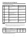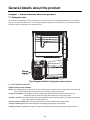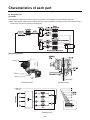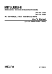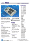
1
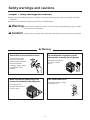
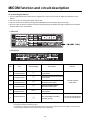
http://biz.lgservice.com
KIMCHI REFRIGERATOR
SERVICE MANUAL
CAUTION
PLEASE READ CAREFULLY THE SAFETY PRECAUTIONS OF THIS MANUAL
BEFORE CHECKING OR OPERATING THE REFRIGERATOR.
MODEL : GR-K24PS/GR-K243UG
Safety regulations
1. First check if there is any electric leakage in the refrigerator unit.
2. Always unplug the refrigerator before handling any electricity conducting parts.
3. When testing the refrigerator with the power on, use insulated gloves for safety.
4. When using measuring instruments, check the rated current, voltage and capacity.
5. Do not allow water or moisture to get into the mechanical or electrical parts of the refrigerator.
6. Remove all things on top of the refrigerator before tilting it during repairs to avoid spills.
Be especially careful for thin objects (glass sheet, book).
7. When the refrigerating cycle is damaged, always request service to the major repair service agency.
(This is to prevent the house from getting dirty from the gas within the cycle.)
8. Always double check for repairs related to safety to ensure customer safety.
Contents
1. Safety warnings and cautions .......................................................................................................................3
2. Product specification .....................................................................................................................................6
3. Product installation method ..........................................................................................................................7
4. Circuit diagram ...............................................................................................................................................8
5. MICOM function and circuit description.......................................................................................................9
6. Freezing cycle and refrigerant.....................................................................................................................32
7. General details about the product ..............................................................................................................34
8. Characteristics of each part ........................................................................................................................36
9. Cautions for disassembling the product ....................................................................................................41
10. Assembly diagram and service parts list .................................................................................................42
-2-
Safety warnings and cautions
Chapter 1. Safety warnings and cautions
u Always observe the 'Safety Warnings' and 'Cautions', which hare intended to ensure safety while repairing or operating
the product.
u Precautions are classified into 'Warning' and 'Caution', as explained below.
w Warning Warning means a dangerous condition which could result in significant damage, injury or death if
the instructions are not followed.
w Caution
Caution means a condition which could result in damage or injury if instructions are not followed.
w Warning
Use caution to prevent electric shock
Do not allow the consumer to repair,
disassemble or modify the refrigerator.
The control panel (main
PCB) uses 310V. When
replacing PCB parts, wait at
least 3 minutes after
unplugging. Always unplug
the refrigerator before
repairing.
Damaged power plug can
cause fire or electric
shock.
Make sure that the power plug is not
pressed by the back of the refrigerator
Use a dedicated circuit.
Overloading circuits or outlets
could cause a fire.
Power plug may be
damaged and cause a fire
or electric shock.
-3-
Safety warnings and cautions
w Warning
This product should always be
grounded, when needed.
Do not store flammable liquid or gas in
the refrigerator such as ether, benzene,
alcohol, medicine, LP gas etc.
If you think that there is a possibility of electricity
leakage by water or moisture, always ground the unit.
It can cause an explosion or a fire.
Grounding screw
Grounding line
Ether
More than 75cm
Copper plate
Do not store medicine or academic
material etc. in the refrigerator.
Store an object that
requires precise
temperature control
can cause deterioration
in quality or
unexpected reaction to
cause a dangerous
situation.
Benzene
gas
When disposing the refrigerator,
remove the rubber packing on the door
and do not leave it where children play.
A child can be
dangerously entrapped in
the refrigerator.
Academic
material
e
icin
Med
Do not set items, particularly flower
vase, cup, cosmetic or medicine on top
of the refrigerator.
Do not stack items or carelessly store
food on the refrigerator.
Items stored on the
refrigerator could fall
and cause injury.
It can cause fire and
electric shock or cause an
injury from dropping.
-4-
Safety warnings and cautions
w Caution
When using the refrigerator for low
temperature in freezer or refrigerator,
do not store bottles.
Always use exact replacement parts.
Make sure that the model name, voltage, current and
temperature ratings are correct for the electric part.
Bottles can freeze and cause the bottles to crack,
which can cause an injury.
Rated parts
During repairs, be sure all connectors
are tight and wires are properly routed.
Do not bend, modify, bend, pull or twist
the power cord.
Make sure the connectors of the housing part are
properly connected.
It can cause fire or electric shock.
During repairs, remove all dust and
foreign material from the housing part,
connector part and check part.
Allow at least 5 minutes for resetting if
you unplug the refrigerator.
If can cause an
overload to the
condenser operation
and cause problems.
It can prevent problems such as tracking or short
circuit.
-5-
r
Afte
tes
minu
Product specification
Chapter 2. Product specification
2-1. GR-K24PS/GR-K243UG
Item
Volume
External
dimensions
GR-K24PS
GR-K243UG
Usable volume
238Li
242.6Li
Top left compartment
92Li
94.3Li
Top right compartment
92Li
94.3Li
Bottom left compartment
27Li
27Li
Bottom right compartment
27Li
27Li
Width
922mm
922mm
Depth
712mm
699mm
Height
975mm
975mm
88kg
87kg
Total weight
Motor power consumption
108W
Cooling method
Direct cooling
Store/Season
Electronic
Icing removing method
Manual start, manual end
Insulation material
CYCLO PENTANE
Fresh vegetable basket
1pc
Kimchi storage container
8pcs
Drawer storage container
1pc
Chungukjang fermenting container
1pc
Low temperature catalytic deodorizing system
2pcs
Freeze cycle
Compressor
MA57LAQF
Evaporator
PIPE ON SHEET
Refrigerant
R134a(165g)
Oil
Freol 10G (220cc)
PTC
P6R8MA
Overload protection device
4TM412RFBYY
Electrical part rating
Fan motor for compressor cooling
ø110, 3blades attached
Lid left compartment Kimchi seasoning heater
115V / 80W (Resistance: 165Ω)
Lid right compartment Kimchi seasoning heater
115V / 80W (Resistance: 165Ω)
Drawer left compartment Kimchi seasoning heater
115V / 8W (Resistance: 1,653Ω)
Drawer left compartment Chungukjang seasoning heater
115V / 6W (Resistance: 2,204Ω)
Drawer right compartment rice storage heater
115V / 8W (Resistance: 1,653Ω)
Capacitor
CS: 160 VAC 100µF
-6-
Product installation method
Chapter 3. Product installation method
3-1. Method to adjust height of refrigerator
■ First adjust the level of the refrigerator.
(If the floor is uneven, the refrigerator may vibrate or cause noise.)
GR-K24PS
Horizontal adjustment leg
(lower handle part)
u Adjust the front to be leveled by turning the height adjustment screws under the front corners in the arrow direction.
3-2. Grounding method
1. In the following cases, you must always ground the refrigerator.
1) When using the refrigerator in the 110V region
2) When using the refrigerator in the 220V region where the power
outlet is not grounded to the side.
2. You must install a circuit breaker (rated current 15mA, rated
non-operating current 7.5mA) if it is difficult to ground the
refrigerator. For the circuit breaker, you can purchase and use the
one with plug and outlet.
3. For the grounding connector on back of the refrigerator, use a connecting line with a diameter of 1.6mm or longer or a
single core cord line with a nominal cross section area of 1.25mm or bigger. After soldering, bury the copper plate 75cm
or deeper from the ground.
u Size of copper plate: Thickness (0.7mm or more), area (90cm or more)
Caution
Do not ground the circuit in one of the following places:
1. Water pipe: If there is a plastic piping within the system, the ground may not be valid.
2. Gas pipe: There is a danger of fire or exposition.
3. Phone line or lightning rod: If lightening strikes, dangerous voltage may be induced in the circuit.
-7-
Circuit diagram
Chapter 4. Circuit diagram
-8-
MICOM function and circuit description
Chapter 5. MICOM function and circuit description
5-1. Function description
5-1-1. Display part
1) GR-K24PS
2) GR-K243UG
NOTCH
Cabbage/Radish/Mul Kimchi
Min
Temperature 0°C
Mid
Max
-1.0°C -2.0°C
Vegetable/Fruit
Min
Mid
Max
3.5°C 2.5°C 1.5°C
Light freezing
Min
Mid
Freezing food
Rice
Max
Min
Mid
Max
Min
Mid
-4.0°C -5.0°C -6.0°C
-15°C
-18°C
-21°C 10.5°C 10°C
Chungukjang
Max
Min
Mid
Max
9.5°C 2.0°C
1.0°C
0°C
1. When the power is connected for the first time, it is set to “Lock”, “Left compartment-Cabbage Kimchi-Mid” and “Right
compartment-Cabbage Kimchi-Mid”.
2. During a power shut-down or when the power is reconnected, the refrigerator maintains the prior display. But in case of a
power-shut down or power reconnection during rhythm fermenting, the temperature returns to “Mid” for the applicable
food type.
3. In “Lock” status, you will not hear a buzzer even when you press the buttons and the functions will not work.
But even in the Lock status, if you press the “Compartment selection” button, it will operate in the order of “Lid left
compartment” ’ “Lid right compartment” ’ “Drawer right compartment” ’ “Drawer left compartment” to show you the
selected display.
-9-
MICOM function and circuit description
5-1-2. Food storage/seasoning function
(1) When selecting food type and storing temperature
1. Press the “Lock/Unlock” button for more than 2 seconds to switch to “Unlock” status.
2. Press the “Compartment selection” button to select the compartment to use.
3. Press the “Store” button to change the storing temperature to “Mid” ’ “Max” ’ “Min” ’ “Mid”. The food type changes as
follows. (“Cabbage Kimchi” ’ “Radish Kimchi” ’ “Mul Kimchi” ’ “Vegetable/Fruit” ’ “Light Freeze” ’ “Freeze” ’ “Old
Kimchi” ’ “Chungukjang” ’ “Rice”.) But the selected food type differs by the “Compartment selection”.
4. Press the “Lock/Unlock” button to complete the selection of food type and storing temperature. At this time, if a minute
passes without pressing the “Lock/Unlock” button, it will automatically switch to Lock status and end the food type and
storing temperature selection mode.
(2) When selecting food type and rhythm fermenting (seasoning)
1. Press the “Lock/Unlock” button for more than 2 seconds to switch to “Unlock” status.
2. Press the “Compartment selection” button to select the compartment to use.
3. Press the “Ferment” button to change the seasoning stage to “Seasoning” ’ “Seasoning+>” ’ “Mature seasoning” ’
“Underground fermenting” ’ “Fresh seasoning” ’ “Fresh seasoning+>” ’ “Seasoning”. The food type changes as follows
as the seasoning degree changes from “Fresh seasoning+>” ’ “Seasoning”. (“Cabbage Kimchi” ’ Radish Kimchi” ’ Mul
Kimchi” ’ “Old Kimchi” ’ ”Chungukjang”.). But the seasoning stage for old Kimchi and Chungukjang changes from
“Seasoning” ’ “Mature seasoning” ’ “Fresh seasoning” ’ “Seasoning”, and the underground fermenting only works for
the cabbage Kimchi in the lid right compartment. Also selected food type differs by the “Compartment selection”.
4. Press the “Lock/Unlock” button to complete the rhythm fermenting. At this time, if a minute passes without pressing the
“Lock/Unlock” button, it will automatically switch to Lock status and end the rhythm ferment (seasoning) selection mode.
5. When the rhythm fermenting selection is completed, the remaining time is indicated and when seasoning is done, the
remaining time will be “0 hours”. And the storing temperature will automatically be set to “Mid”.
(3) When selecting flavor keeping
1. Press the “Lock/Unlock” button for more than 2 seconds to switch to “Unlock” status.
2. Press the “Compartment selection” button to select the compartment to use.
3. At this time, press the “Flavor keeping” button to select or cancel the flavor keeping function. (But the flavor keeping
function only applies to the Cabbage Kimchi, Radish Kimchi and Mul Kimchi in the lid left and right compartment.)
4. Press the “Lock/Unlock” button to end the flavor keeping selection mode. At this time, if a minute passes without pressing
the “Lock/Unlock” button, it will automatically switch to Lock status and end the flavor keeping selection mode.
5. If you select flavor keeping during seasoning process, it will immediately end the seasoning and switch to flavor keeping.
At this time the storing temperature will automatically be set to “Mid”.
6. If you select the flavor keeping function, the refrigerator will lower the temperature to maintain the current Kimchi flavor.
(-1 degrees for “Min”, -0.5 degrees for “Mid” and -0 degrees for “Max”.)
7. During flavor keeping operation, a cold shock operation is done every 12 hours.
8. If you select rhythm fermenting during flavor keeping, the flavor keeping function will be canceled.
- 10 -
MICOM function and circuit description
5-1-3. When selecting power on/off function
1. Press the “Lock/Unlock” button for more than 2 seconds to switch to “Unlock” status.
2. Press the “Compartment selection” button to select the compartment.
3. At this time, press the “Power” button for more than 2 seconds to turn the power off.
4. At this time, all the LEDs in the display will be turned off with the power off LED turning on.
5. If you press the “Power” button when the power is off, it will turn on the power and recover to “Cabbage Kimchi” and
“Mid”.
6. When the power is turned off, the heater of the applicable compartment is turned off and the valve will be closed.
5-1-4. Rhythm fermenting control pattern diagram
Kimchi sensor temperature
: Seasoning heater ON/OFF
When the K
imch
in the refrig i placed
er
at room tem ator is
perature
)
When the Kim
chi
in the refrigera placed
tor is cool
: Seasoning heater OFF
Mul Kimchi (10
Time
Storage operation
1st seasoning
2nd seasoning
3rd seasoning
4th seasoning
Seasoning start
5th seasoning
Seasoning complete
1. The fermenting control pattern varies, depending on the temperature of the Kimchi when it is placed into the storage, the
type of Kimchi being made and the degree of the seasoning selected.
2. In the 1st seasoning cycle, if the Kimchi is at room temperature, the cold control operates.
3. During the seasoning cycle, if the Kimchi is cold, the seasoning heater is turned on and if the Kimchi is warm, the
seasoning heater is turned off.
4. If a failure occurs, such as a sensor error during seasoning, the storage will default to Cabbage Kimchi storage status.
- 11 -
MICOM function and circuit description
5-1-5. Temperature control method
1. The compressor runs or stops and the 3-way valve opens or closes depending on the temperature sensed by each
sensor.
2. If the temperature in either compartment is unsatisfactory, the compressor is turned on and the 3-way value is opened to
the affected compartment.
3. If the temperatures in several compartments are unsatisfactory, the compressor is turned on and runs until both
compartments become satisfactory. The 3-way valve is opened and closed for each compartment until the temperature is
satisfactory.
4. During the seasoning cycle, if the temperature is low, the heater is turned on and if the temperature is high, the
compressor is turned on and the 3-way value is opened.
5-1-6. Buzzer sound
When you press a button on the front display, you will hear “ding dong” sound. (Refer to 5-2-4. (2) Buzzer operating circuit).
5-1-7 Power failure compensation function
1. When the power is restored after an outage, the refrigerator performs the setting originally programmed except for Error
status and Test mode.
2. If the power fails during the seasoning process, there is not power outage compensation function and the storage defaults
to previously set Kimchi type and temperature of “Mid”. (to protect excessive seasoning)
5-1-8. Operation in response to ambient temperature
The storage senses the ambient temperature and adjusts the temperature in the compartments accordingly. This keeps the
storage from being too cold or too warm because of seasonal variations and maintains exact temperatures in the
compartments.
In general operation
Storage
temperature
Operation in response to the ambient temperature
Season
Spring
Summer
Autumn
- 12 -
Winter
MICOM function and circuit description
5-1-9. Sequential operation of components
Components (compressor, 3-way valve, lid left compartment seasoning heater, lid right compartment seasoning heater,
drawer left compartment heater and drawer right compartment heater) are operated in a specific order to prevent damage
and noise caused by simultaneous operation of all parts when the unit is started and after completing the self-test routine.
Operation status
Operating order
Immediately
Temperature of
the left of right
sensor is >10°C
3 min
Immediately
10 sec
3-way
valve
left
open
3-way
valve
open
Power
on
0.5 sec
Compressor
on
5 sec
Initial power-up
Power
on
Lid left
compartment
seasoning
heater on
Lid right
compartment
seasoning
heater on
0.5 sec
0.5 sec
0.5 sec
Lid left
compartment
seasoning
heater off
Temperature of
the left of right
sensor is <10°C
Remarks
Lid right
compartment
seasoning
heater off
0.3 sec
0.5 sec
Drawer left
compartment
seasoning
heater on
0.5 sec
Drawer left
compartment
seasoning
heater off
3 min
Drawer right
compartment
seasoning
heater off
Compressor
on
10 sec
3-way
valve lid right
compartment
open
3-way
valve
open
All
7 min
loads
When returning to
normal status in test
mode
Drawer right
compartment
seasoning
heater on
Compressor
on
off
0.3 sec
3 min
3-way
valve
open
3-way
valve left
open
g Operation order may slightly vary depending on temperature setting.
- 13 -
The 3-way valve is
opened to both
compartments for
3 minutes; then it is
opened to lid
left/right
compartment or
drawer left/right
compartment.
MICOM function and circuit description
5-1-10. Error diagnosis function
1. The error diagnosis function is the function to support SVC in case of an error that can affect the performance of the
product.
2. If an error occurs, the control panel button will not work.
3. If an error occurs and is resolved, the refrigerator will default to the normal status. (The unit is reset.)
4. The error codes are shown in segment for the remaining seasoning time display of the right compartment, and all LEDs,
except for failure code, are turned off.
1) GR-K24PS
2) GR-K243UG
NO
Item
Error code display
Error contents
1
Failure of lid left
compartment sensor
E1
Lid left compartment sensor disconnected
or short circuited
2
Failure of lid right
compartment sensor
E2
Lid right compartment sensor disconnected
or short circuited
3
Failure of drawer left
compartment sensor
E3
Drawer left compartment sensor
disconnected or short circuited
4
Failure of drawer right
compartment sensor
E4
Drawer right compartment sensor
disconnected or short circuited
5
Failure of outside
temperature sensor
Note 1)
6
Communications error
CO
Note 1)
Remarks
* Check the connection
of each sensor
Outside temperature sensor disconnected
or short circuited
When communication is not working
continuously for 30 sec
The connector could be pulled out.
Poor TR in communications part
A. For display 1) ,press the “compartment selection” and “store” button simultaneously, all LED’s will turn on except the
remaining fermentation time displaying LED’s.
B. For display 2) , press the left lid compartment store button and right lid compartment store button together all LED’s will turn
on except right lid compartment remaining fermentation time display LED’s.
- 14 -
MICOM function and circuit description
5-1-11. Test function
1. The test function checks the functions of the PCB and the refrigerator, searching for errors in parts.
2. The test switch on the PCB operates the test mode. The refrigerator reverts to the normal mode after 2 hours if you forget
to end it manually.
3. When the test mode is active, the buttons on the control panel are disabled but the buzzer still sounds a ding if one is
pressed.
4. When the test mode is completed, unplug the refrigerator briefly and plug it in again to reset it and allow normal
operation.
5. If a sensor failure or other failure is detected during the test mode, release the test mode to display the failure code.
6. During the display of the error code, test mode does not work even if you press the Test switch.
Mode
Operation
Test 1
Press the test
(lid left
switch once
compartment
cooling
power
mode)
Contents
Remarks
1) Compressor ON.
2) 3-way valve open
3) Heater all off
4) Display “11”
g The system recovers to
the initial status after a
maximum of 2 hours.
Test 2 (lid
right
compartment
cooling
power
mode)
Press the test
switch once when
Test 1 indicates it is
completed.
1) Compressor ON.
2) 3-way valve open
3) Heater all off
4) Display “22”
g The system recovers to
the initial status after a
maximum of 2 hours.
Test 3
(drawer
left
compartment
cooling
power
mode)
Press the test
switch once when
Test 2 indicates it is
completed.
1) Compressor ON.
2) 3-way valve open
3) Heater all off
4) Display “33”
g The system recovers to
the initial status after a
maximum of 2 hours.
Test 4
(drawer
right
compartm
ent cooling
power
mode)
Press the test
switch once when
Test 3 indicates it is
completed.
1) Compressor ON.
2) 3-way valve open
3) Heater all off
4) Display “44”
g The system recovers to
the initial status after a
maximum of 2 hours.
Press the test
Normal switch once when
recovery Test 4 indicates it is
completed.
Returns to initial status (COMP 7 min delay)
- 15 -
MICOM function and circuit description
5-2. Circuit description
5-2-1. Power circuit
The power circuit consists of the noise attenuation part and the SMPS (Switch Mode Power Supply) part. The SMPS
consists of the rectifier (BD1 & CE1) to convert AC voltage to DC voltage, switching part (IC3) to switch the converted DC
voltage, transformer to transmit energy of the first side of the switching end to the second side, the secondary power to
supply power to MICOM and IC, and the feedback part (IC4) to feedback the secondary voltage to the first side of the
transformer in order to maintain the secondary voltage constant.
Caution
: High voltage (DC 310V) is maintained in this circuit. Wait at least 3 minutes after unplugging to allow the
current to dissipate. There is a danger of electric shock.
5-2-2. Oscillation circuit
The oscillation circuit provides the clock signal for
synchronization and calculation of time in relation
to the logic elements of microprocessor IC1
(MICOM). OSC1 must always use the original
rated parts, because if the specification changes,
the timing generated will not be correct, causing
erratic functioning of the microprocessor.
OSC1
CSTLS4M00G53
5-2-3. Reset circuit
The reset circuit allows the entire process to be
started from the initial status by resetting the
various elements within the MICOM (IC1), such as
RAM, whenever power is applied to the unit. Low
voltage is applied to the reset terminal for 10ms at
the beginning of the power input. The reset
terminal has a voltage of 5 V during general
operation. (If the reset operation fails, the
microprocessor will not operate.)
- 16 -
MICOM function and circuit description
5-2-4. Load/Buzzer driving circuit
(1) Load driving circuit
Type of load
COMP. fan motor
Lid left compartment
seasoning heater
Lid right compartment
seasoning heater
Measuring point(IC7)
10
11
12
Drawer left compartment
Drawer right
Drawer left compartment
seasoning heater
compartment rice heater Chungukjang heater
13
ON
Within 1V
OFF
12~13V
14
15
Status
(2) Buzzer driving circuit (located on display PCB)
LED MODULE TYPE
Status
Measuring
point
“Ding-Dong” sound(Ding-)(Dong-)
45ms 45ms 45ms 45ms 70ms
IC101 (Pin 3/61)
“Ding” sound(Ding-)
750ms
45ms 45ms 45ms 45ms 70ms
5V
5V
0V
0V
5V
5V
IC101 (Pin 2/62)
0V
1046.5Hz 1174.7Hz
0V
1318.5Hz
- 17 -
Off
750ms
5V
0V
1568.0Hz 1318.5Hz
1046.5Hz
MICOM function and circuit description
5-2-5. Switch input circuit
The following circuit is the input circuit to detect the test switch signal to check the refrigerator.
RAR2
10K
5-2-6. Temperature sensor circuit
The following temperature sensor circuit consists of a sensor to detect the outside (ambient) temperature, sensors in the lid
left and right compartment, sensor in the drawer left and right compartment for storing and seasoning Kimchi. The status of
each sensor, whether open or shorted, is shown below.
CON5
CON4
CON3
CON2
Sensor
Check point
Drawer right compartment sensor
POINT A Voltage
Drawer left compartment sensor
POINT B Voltage
Lid right compartment sensor
POINT C Voltage
Lid left compartment sensor
POINT D Voltage
Outside sensor
POINT E Voltage
- 18 -
Normal(-30°C~50°C)
Shorted
Open
0.5V~4.5V
0V
5V
MICOM function and circuit description
5-2-7. Stepping motor operation circuit (3-way valve)
u The motor is operated by sending out “High” and “Low” signals as many as the designated number of steps through
MICOM Pin 44, 43, 46, 45 (lid part) and 48, 47, 50, 49 (drawer part) to rotate the motor through the magnetic field formed
by the motor and the coil wrapped around each stator.
5-2-8. Power failure compensation circuit (located on display PCB)
LED MODULE TYPE
uThe power failure compensation circuit recalls the temperature range of the right and left compartment for lid and drawer,
and maintains these levels if power if interrupted briefly.
The IC for power failure compensation (EEPROM) delivers to and maintains the information in MICOM through the serial
interface.
- 19 -
MICOM function and circuit description
5-2-9. Storing temperature compensation and over-cool/under-cool cut compensation circuit
(1) Storing temperature compensation
u This is the circuit to input the temperature compensation level required for adjusting storage temperature at the left or
right compartment of the lid or drawer.
Lid left compartment
(RCUL)
Lid right compartment Drawer left compartment Drawer right compartment
Temperature
compensation value
Remarks
180 KΩ
+2.5 ˚C
Warmer
56 KΩ
+2.0 ˚C
33 KΩ
+1.5 ˚C
18 KΩ
+1.0 ˚C
12 KΩ
+0.5 ˚C
10 KΩ
0 ˚C
8.2 KΩ
-0.5 ˚C
5.6 KΩ
-1.0 ˚C
3.3 KΩ
-1.5 ˚C
2 KΩ
-2.0 ˚C
470 Ω
-2.5 ˚C
(RCUR)
(RCBL)
(RCBR)
Standard temperature
Cooler
u Temperature compensation table by adjustment of resistance value (difference against current temperature)
Ex) If you change the resistance of compensation at the lid left compartment (RCL) from 10KΩ (current resistance) to
18KΩ (adjusted resistance), the storage temperature in the lid left compartment will be increased by 1°C .
Classification
Lid left
compartment
(RCUL)
Lid right
compartment
(RCUR)
Drawer left
compartment
(RCBL)
Drawer right
compartment
(RCBR)
Modified
resistance
Current
resistance
470 Ω
2 KΩ
3.3 KΩ
5.6 KΩ
8.2 KΩ
10 KΩ
12 KΩ
18 KΩ
33 KΩ
56 KΩ
180 KΩ
470KΩ
No change
0.5°C UP
1°C UP
1.5°C UP
2°C UP
2.5°C UP
3°C UP
3.5°C UP
4°C UP
4.5°C UP
5°C UP
2 KΩ
0.5°C DOWN No change
0.5°C UP
1°C UP
1.5°C UP
2°C UP
2.5°C UP
3°C UP
3.5°C UP
4°C UP
4.5°C UP
3.3 KΩ
1°C DOWN 0.5°C DOWN No change
0.5°C UP
1°C UP
1.5°C UP
2°C UP
2.5°C UP
3°C UP
3.5°C UP
4°C UP
5.6 KΩ
1.5°C DOWN 1°C DOWN 0.5°C DOWN No change 0.5°C UP
1°C UP
1.5°C UP
2°C UP
2.5°C UP
3°C UP
3.5°C UP
8.2 KΩ
2°C DOWN 1.5°C DOWN 1°C DOWN 0.5°C DOWN No change
0.5°C UP
1°C UP
1.5°C UP
2°C UP
2.5°C UP
3°C UP
10 KΩ
2.5°C DOWN 2°C DOWN 1.5°C DOWN 1°C DOWN 0.5°C DOWN No change
0.5°C UP
1°C UP
1.5°C UP
2°C UP
2.5°C UP
12 KΩ
3°C DOWN 2.5°C DOWN 2°C DOWN 1.5°C DOWN 1°C DOWN 0.5°C DOWN No change 0.5°C UP
1°C UP
1.5°C UP
2°C UP
18 KΩ
3.5°C DOWN 3°C DOWN 2.5°C DOWN 2°C DOWN 1.5°C DOWN 1°C DOWN 0.5°C DOWN No change
0.5°C UP
1°C UP
1.5°C UP
33 KΩ
4°C DOWN 3.5°C DOWN 3°C DOWN 2.5°C DOWN 2°C DOWN 1.5°C DOWN 1°C DOWN 0.5°C DOWN No change
0.5°C UP
1°C UP
56 KΩ
4.5°C DOWN 4°C DOWN 3.5°C DOWN 3°C DOWN 2.5°C DOWN 2°C DOWN 1.5°C DOWN 1°C DOWN 0.5°C DOWN No change
0.5°C UP
180 KΩ
5°C DOWN 4.5°C DOWN 4°C DOWN 3.5°C DOWN 3°C DOWN 2.5°C DOWN 2°C DOWN 1.5°C DOWN 1°C DOWN 0.5°C DOWN No change
- 20 -
MICOM function and circuit description
(2) Over-cool/Under-cool cut compensation
Lid left compartment cut
Lid right compartment cut
Drawer left compartment cut
Lid right
Drawer left Drawer left compartment storing
Lid left
temperature compensation
compensation
compensation
compensation
compartment
compartment
compartment
Over-cool
Under-cool
Over-cool
Under-cool
Over-cool
Under-cool
Over-cool
Under-cool
storing
storing
storing
compensation compensation
compensation compensation
compensation compensation
compensation compensation
temperature
temperature
temperature
JCUL1
JCUL2
JCUR2 compensation JCBL1
JCBL2 compensation JCBR1
JCBR2
compensation JCUR1
CUT
CUT
+1°C
CUT
-1°C
CUT
0°C
0¡
(Factory default)
CUT
CUT
+1°C
CUT
-1°C
CUT
0°C
CUT
CUT
0¡
(Factory default)
+1°C
CUT
-1°C
CUT
0°C
0¡
(Factory default)
CUT
CUT
Drawer right
compartment
storing
temperature
compensation
+1°C
CUT
-1°C
CUT
0°C
0¡
(Factory default)
u The cut compensation circuit compensates the storing temperature of the left or right compartment of the lid or drawer by
simply cutting it out of service for a brief period.
- 21 -
MICOM function and circuit description
5-2-10. Communication circuit between main PCB and display PCB
This circuit provides communications between the MICOM on the main PCB and the MICOM of the display PCB.
If there is no communication between these boards for 30 seconds, a communication error occurs.
MICOM for
LED/LCD control
Send (Error status)
Receive (Notch status)
PWB(PCB) ASSEMBLY, MAIN
PWB(PCB) ASSEMBLY, DISPLAY
- 22 -
MICOM function and circuit description
5-2-11. Button input and display part illumination circuit
This circuit determines which buttons are pressed and drives the LED display, whose driving method is a scan method.
PREMIUM/STANDARD/FIGHTING (LED MODULE TYPE)
D110
D111
D112
D113
D114
D115
- 23 -
IN4004X6
MICOM function and circuit description
PREMIUM MODERN COLOR (LED MODULE TYPE)
D110
- 24 -
MICOM function and circuit description
5-3. Sensor resistance characteristics table
Measuring temperature (°C)
Lid left compartment, lid right compartment, drawer left
compartment, drawer right compartment, outside sensor
-20°C
77 KΩ
-15°C
60 KΩ
-10°C
47.3 KΩ
-5°C
38.4 KΩ
0°C
30 KΩ
+5°C
24.1 KΩ
+10°C
19.5 KΩ
+15°C
15.9 KΩ
+20°C
13 KΩ
+25°C
11 KΩ
+30°C
8.9 KΩ
+40°C
6.2 KΩ
+50°C
4.3 KΩ
CON5
CON4
CON3
CON2
u The tolerance of the sensor resistance is °±3%.
u Measure the resistance value of the sensor after leaving it for more than 3 minutes (delay is required due to sensing
speed.)
u Always use a digital tester. Analog testers have a higher margin of error.
u For left and right sensor of lid and drawer, measure both sensor ends of the connector after separating the connectors of
CON 2, 3, 4, 5, CON101 of PWB (PCB) assembly and main part. For the outside sensor, measure end of 2 and 5 of
CON101.
- 25 -
MICOM function and circuit description
5-4. PCB parts diagram and parts list
5-4-1. PWB (PCB) assembly and main parts diagram
- 26 -
MICOM function and circuit description
5-4-2. PWB (PCB) assembly and main parts list
g The parts list can slightly change according to the situation.
ATHENA1-PJT
G
YW396-10AV(10P-1,2,4,6,8,10)BLUE
YW396-09AV(9P-1,3,5,8)YELLOW
Z
DH12D1-O-Q
GBL06
- 27 -
MICOM function and circuit description
- 28 -
MICOM function and circuit description
5-4-3. PWB (PCB) assembly and display parts diagram and parts list (6871JB1395_)
g The parts diagram and parts list can slightly change according to the situation.
- 29 -
MICOM function and circuit description
- 30 -
MICOM function and circuit description
5-4-3. PWB (PCB) assembly, sub parts diagram and parts list (common for 6871JB2073A/B left and right)
g The parts diagram and parts list can slightly change according to the situation.
- 31 -
MICOM function and circuit description
5-5. PCB circuit diagram
5-5-1. PWB (PCB) assembly and main circuit diagram (6871JB1246)
g PCB circuit diagram can slightly change according to the situation.
- 32 -
MICOM function and circuit description
PWB(PCB) ASSEMBLY, DISPLAY
:6871JB1395, 6871JB1463
LED
Module
- 33 -
MICOM function and circuit description
5-5-2. PWB (PCB) assembly and display circuit diagram (6871JB1395_)
g The circuit diagram can slightly change according to the situation.
g This includes the PWB (PCB) assembly and sub circuit diagram.
D110
D111
D112
D113
D114
D115
- 34 -
IN4004X6
MICOM function and circuit description
- 35 -
Freezing cycle and refrigerant
Chapter 6. Freezing cycle and refrigerant
6-1. Freezing cycle (Freezing principle/Refrigerant gas circulation diagram)
6-1-1. Freezing principle
Freezing is an operation of maintaining a lower temperature (generally 0°…) than the natural temperature (usually ambient
temperature surrounding us). This requires an insulated space, refrigerant (R134a) to absorb the heat and the circulation
circuit (compressor, condenser, evaporator etc.) to operate the phase change of the refrigerant.
6-1-2. Refrigerant gas circulation diagram
1. Compressor
2. Wire condenser
3. Drier
4. 3-way valve (2 EA)
5. Capillary tube (lid left)
6. Capillary tube (lid right)
10
9
7. Capillary tube (drawer left)
8. Capillary tube (drawer right)
9. Evaporator (lid left)
10. Evaporator (lid right)
11. Evaporator (drawer left)
12. Evaporator (drawer right)
13. Suction pipe
14. Cooling fan
5
6
7
11
4
4
14
13
1
- 36 -
8
3
12
2
Freezing cycle and refrigerant
6-1-3. Operation description of each circulation circuit
No.
Parts name
Operation details
Refrigerant gas condition (input and output)
1
Compressor
Compress the refrigerant from low pressure
to high pressure.
Low pressure gas¡ High pressure gas
Temperature(30°C)¡ (80~120°C)
2
Condenser
High pressure gas refrigerant exhausts heat
and becomes liquid refrigerant.
High pressure gas¡ High pressure liquid
Temperature(80~120°C)¡ (40~60°C)
3
Drier
There is an absorbent that absorbs the
moisture within the circulation circuit.
(Moisture absorption device)
4
Capillary tube
This is the long narrow pipe where high
pressure refrigerant passes to reduce the
pressure.
High pressure liquid¡ Low pressure liquid
Temperature(40~60°C)¡ (-27°C)
5
Evaporator
Low pressure liquid refrigerant absorbs heat
to change to low pressure gas refrigerant.
Low pressure liquid¡ Low pressure gas
Temperature(-27°C)
6
Suction pipe
This connects the evaporator and the
compressor.
Low pressure gas¡ Low pressure gas
Temperature(-27°C)¡ (30°C)
Caution
u Because the outlet of the capillary tube is where the high pressure refrigerant changes from high to low
pressure, the low pressure refrigerant quickly diffuses to the evaporator, making flash sounds. (shik shik
sound)
u When the low pressure liquid refrigerant evaporates from the evaporator, it is done throughout the whole
pipe from inlet to outlet, making a sound of liquid refrigerant flowing. This can happen depending on the
load condition of the refrigerator and on the evaporation, but it is not a problem.
6-2. Refrigerant
Refrigerant
name
R134a
(ISO butane)
Characteristics
ODP
GWP
Remarks
R134a is highly explosive (ISO butane) and need extra
special care during refrigerator manufacturing and
servicing. As an environmental friendly refrigerant, the ODP
and GWP is respectively 0.
0
1200
Refrigerant
g ODP: Ozone Depleting Potential (Relative index with CFC11 as 1.0)
GWP: Global Warming Potential (Relative index with CO2 as 1.0)
- 37 -
General details about the product
Chapter 7. General details about the product
7-1. Refrigerator noise
The structure of the freezing room and mechanical room, which are the sources of Kimchi refrigerator noise, is as follows.
Here you can see that the main source of noise during refrigerator operation is the compressor, the condenser and the fan
motor that cools the compressor in the mechanical room.
(Fig. Diagram of Kimchi refrigerator noise source)
7-1-1. SVC method for noise claim
•
(1) Basic method of noise reduction
• Block: This method blocks the noise from the source so that it does not reach the ears by blocking the transmission path
of the sound with high density sound blocker. (This is effective in high frequency area)
• Using sound absorber: This method is similar to the blocking method but uses Styrofoam and glass wool in the
transmission path to absorb the sound. (This is effective in low frequency area)
• Vibration reduction: This method blocks the mechanical vibration from the operating part so that it does not reach other
parts. (using vibration reduction rubber etc.)
• Dynamic balance maintenance: This method minimizes the dynamic imbalance of the rotating object.
• Fixing the vibrating part: This method firmly fixes the vibrating part depending on the situation.
• Removing contact: Separate the two parts or firmly fix the object that periodically make sound by hitting each other.
- 38 -
General details about the product
(2) Service method for major noise claim item for Kimchi refrigerator
Noise claim
Noise generation
Service method
Noise from poor
installation
u The installation floor surface is
not hard enough
u The refrigerator is not leveled
• Reinforce the floor hardness
• Move the installation location
• Use the adjustment screw in
front of the refrigerator to level
the refrigerator
Parts vibration
u “Wing” sound
• Insert firmly all the parts of the
refrigerator in the right location
Compressor
resonance sound
u “Woong Woong” sound
• Reduce the noise by adjusting
the pipe and seat rubber
Compressor noise
u Poor balance of the compressor
u Contacting sound of the
surrounding pipe of the
compressor part
• Adjust the surrounding pipe and
seat rubber to maintain the
level of the compressor
• Remove contact
Operating device
noise
u Contact sound from the OLP
contact point during compressor
operation
• Exchange OLP
Wire condenser
noise (vibration
noise)
u “Woong Woong” sound
u “Ching” sound
• Recheck the screws
• Remove the welding part of the
heat plate (wire) and remove
the heat plate
Remarks
u Mainly within the
refrigerating
compartment
u “Tak Tak”
7-2. Details on power consumption
The power consumption of the refrigerator is
measured within the chamber where constant
temperature and humidity is maintained. In the
right figure, maintain the chamber to 30°C…
and 75% humidity with no load to the
refrigerator and set the temperature of the left
and right compartment to 3°C… to measure the
power consumption. The power consumption is
calculated as follows.
Monthly power consumption (kWh/month) = Measured value (kWh/day) x 365 days / 12 months
Caution
The actual power consumption and the one indicated on the refrigerator can differ due to the using condition.
- 39 -
Characteristics of each part
8-1. Refrigerant valve
(1) Function
This switches the refrigerant that went through the compressor to the lid left/right or drawer left/right evaporator.
g When connecting the 3-way valve and capillary tube, they must be welded by matching the same color as shown below. If
not matched, it can cause a problem to the refrigerator.
(2) Operating structure
Operating coil
Pipe (inlet)
Valve body
Pipe (outlet)
(External structure)
(Internal structure)
Valve coil
(Operating circuit)
- 40 -
Characteristics of each part
(3) Operating principle
Controlling the rotating angle of the stepping motor will open/close the outlet pipe entrance by changing the shape of the
valve connected to the bottom of the rotor.
Left/Right compartment open
Closed area
Right compartment open Left/Right compartment open Left compartment open
(STEP : 54)
(STEP : 36)
(STEP : 18)
Right side outlet
Valve
Left side outlet
(4) Operating characteristics
- 41 -
Characteristics of each part
8-2. Motor (mechanical room)
(1) Function
• Motor cooling (mechanical room)
This is the part used for circulating the air within the mechanical room and applies to the wire condenser type. This
operates when the compressor operates and the heated refrigerant from the compressor lowers the temperature when
passing through the wire condenser and also reduces the temperature of the compressor to improve the performance.
(2) Operating principle and characteristic
• Characteristic
The motor applied to the refrigerator is the shading pole motor of the inductive motors. As shown below, it is a 2 pole
device with one pole composed of 2 parts. On the small pole called the shading pole, wire is connected (shorted) called
the shading coil. In accordance with the characteristics of the AC motor, the motor switches between + and - to operate but
because in the 2 pole device, the N and S pole changes within both poles without left and right rotation, the device cannot
rotate without help from an external device. Therefore the shading pole and coil creates the rotating direction for operation.
The shading pole motor cannot rotate in reverse direction. Therefore the rotating direction must be set during assembly to
rotate in the desired direction.
Shading
Pole
Shading
Coil
- 42 -
Characteristics of each part
• Operating principle
When the AD power is connected to the coil of the shading pole
motor, the central axis of the magnetic field shifts in the bold
arrow direction of <Fig. 2>. As the central axis moves, the rotor
moves in the same direction to turn the motor.
Why does the central axis of the magnetic field shift?
<Fig. 1> shows a diagram of AC current changing as time
changes. If you look at changes of magnetic velocity in “a” zone
where the current abruptly increases, the velocity increases as
the current increases in the main pole. But in the shading pole,
the negative effect of the velocity increase is generated from the
shading coil to reduce the velocity shifting the center of the
magnetic field to the main pole. In “b” zone, the change in
current is minimal and the negative effect of shading coil is
minimal to have the center of the magnetic field in the middle as
shown in <Fig. 2>. In “c” zone, the velocity of the main pole
decreases but with the negative effect increasing the velocity
from the shading pole side, the center shifts to the shading pole
side. As shown, the center of the magnetic field shifts from the
main pole to the shading pole to rotate the rotor.
Current
a
b
c
Time
<Fig. 1> Change of AC current
Main pole
Shading
Pole
"a"
zone
"b"
zone
"c"
zone
Removal of magnetic velocity on the pole surface
<Fig. 2> Change in magnetic velocity by changes in current
- 43 -
Characteristics of each part
8-3 Heater
(1) Introduction
When using the refrigerator, several heaters are applied to season the Kimchi or store the rice.
(2) Heater type and role
Classification
Heater assembly
Applied part
Function
Resistance value
External surface of inner case For Kimchi seasoning
Remarks
165Ω/EA
80W × 2EA
1,653Ω/EA
8W × 2EA
2,204Ω/EA
6W × 2EA
(Lid-compartment)
Heater assembly
Heater plate
Floor of inner case
For Kimchi seasoning
(Drawer-compartment)
/ rice storage
Left side of inner case (Left
For Chungukjang seasoning
drawer-compartment)
g The resistance value can differ by the model.
■ Heater assembly (ferment/rice storage)
Problem (parts)
1. Heat wire
disconnected/connecting
wire disconnected
2. Poor terminal contact
Symptom
Kimchi not
seasoned
Check method
Resolution
1. Measure the resistance of both
ends of the heater with a tester to
see if it is →∞Ω.
1. Exchange the product
2. Measure the resistance of both
ends of the heater with a tester to
see if it fluctuates.
2. Properly insert the
connector
- 44 -
Cautions for disassembling the product
Chapter 9. Cautions for disassembling the product
1. Main PWB assembly
• When disassembling the main PWB assembly, located
in the mechanical room, be careful so that the lead
wires do not touch the edge part.
• If the lead wire coating is disconnected or the coating is
damaged, it can cause a short circuit.
2. Frame assembly, display
GR-K24PS
• Using the - driver, open the slot between the frame
display and the case-U to disassemble the unit. At this
time, be careful not to apply too much pressure to
damage the PWB assembly, display or make scratches
on frame display and case-U.
g Depending on the mode, the service slot is on the top
left/right side or bottom left/right side.
Frame Display
Case-U
GR-K243UG
Frame Display
Deco, Case
- 45 -
Case-U
Assembly diagram and service parts list
10-3. Assembly diagram
u GR-K24PS
281C
281B
233A
230A
200A
230B
233A
221A
221A
281E
281D
233A
200B
604A
243A
233A
604B
203A
243A
420B
604D
604C
243A
618B
410H
604A
319C
501A
619A
243A
203A
420B
604B
618A
420A
502B
329C
604C
604D
327B
411
319A
323C
318A
323B
307A
310B
314A
327A
309A
310A
308A
312A
315C
315A
315B
- 46 -
304A
Assembly diagram and service parts list
u GR-K24PS
147C
248D
147A
249G
147C
249D
249B
147B
212D
248F
248D
248F
248D
248A
248F
248D
248D
270A
248D
236B
155A
155B
236A
104A
207C
206C
212G
104A
- 47 -
Assembly diagram and service parts list
u GR-K24PS
248D
241B
249A
125C
125D
250A
241A
145B
231A
248B
236D
212B
248G
203B
248C
241A
201A
248B
155C
155C
231B
248G
212A
203B
207D
248C
206G
201B
236C
206F
207D
- 48 -
248B
Assembly diagram and service parts list
u GR-K243UG
200A
281C
281B
233A
230B
230A
222A
233A
281E
233A
222A
281D
200B
233A
243A
203A
243A
420B
604A
604B
243A
604A
203A
618B
319C
500A
420B
243A
410H
619A
604B
420A
502B
329C
618A
319A
327B
323C
411A
318A
323B
307A
310B
314A
327C
309A
310A
308A
312A
315C
315A
315B
- 49 -
304A
Assembly diagram and service parts list
u GR-K243UG
249G
147C
248D
249D
147A
249B
242D
147C
147B
248E
248A
248D
248E
248D
248D
248D
248E
248D
234B
270A
234A
236B
155A
155B
236A
104A
207A
206C
204A
212G
104A
- 50 -
Assembly diagram and service parts list
u GR-K243UG
242A
125C
248D
249A
250A
242B
241A
242B
231A
248B
236D
242C
212B
148B
248G
203B
248C
241A
201A
248B
155C
155C
231B
248G
212A
203B
207B
248C
206G
201B
236C
207C
- 51 -
206F
248B
P/No. MFL31842101
MAR.,2008 Printed in Korea