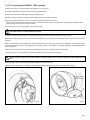
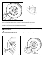
1
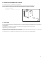
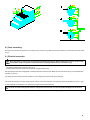
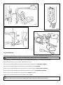
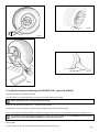
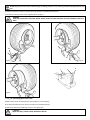
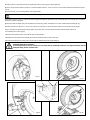
Electro-Hydraulic Tire Changer
For Medium and Large Size Tires
CHD-4730
OPERATING AND MAINTENANCE INSTRUCTIONS
READ these instructions before placing unit in service KEEP
these and other materials delivered with the unit in a binder
near the machine for ease of reference by supervisors and
operators.
85010071/00
Revision 06/08
INDEX
1 - INTRODUCTION...............................................................................................................................................................3
1.1 - Technical data............................................................................................................................................3
2 - DESCRIPTION OF THE MACHINE....................................................................................................................................4
3 - GENERAL ........................................................................................................................................................................5
3.1 - General safety rules...................................................................................................................................5
4 - TRANSPORT.....................................................................................................................................................................6
5 - UNPACKING...................................................................................................................................................................6
6 - INSTALLATION ................................................................................................................................................................7
6.1 Installation site....................................................................................................................................................................................7
6.2 Parts assembling................................................................................................................................................................................7
6.3 Electrical connection.......................................................................................................................................................................8
6.4 Operation test...................................................................................................................................................................................9
7 - operation.....................................................................................................................................................................10
7.1 Notes for operation...........................................................................................................................................................................10
7.2 Rim clamping.....................................................................................................................................................................................11
7.3 Tubeless tires.......................................................................................................................................................................................12
7.3.1 Bead loosening and demounting with roller tool.......................................................................................................12
7.3.2 Bead loosening and demounting with DOUBLE roller tool.......................................................................................12
7.3.3 loosening and demounting with DOUBLE tool................................................................................................................13
7.3.4Tire mounting with ROLLER TOOL.....................................................................................................................................14
7.3.5 Tire mounting with DOUBLE tool.....................................................................................................................................16
7.4 Tube tires............................................................................................................................................................................................18
7.4.1 Bead breaking and tyre removing with double tool.....................................................................................................18
7.4.2 Tire mounting with DOUBLE TOOL....................................................................................................................................19
7.5 Tire assembly with 3 pieces split ring..................................................................................................................................................21
7.5.1 Bead loosening and demounting with double tool.......................................................................................................21
7.5.2 Tire mounting with DOUBLE TOOL....................................................................................................................................22
7.6 Tire assembly 5 pieces split ring.........................................................................................................................................................23
7.6.1 Bead breaking and demounting with double tool........................................................................................................23
7.6.2 Tire mounting with DOUBLE TOOL....................................................................................................................................24 8 - RESITING........................................................................................................................................................................25
9 - STORING........................................................................................................................................................................25
10 - SCRAPPING.................................................................................................................................................................25
11- OIL TREATMENT.............................................................................................................................................................26
12 - FIRE FIGHTING MEANS.................................................................................................................................................26
13 - ORDINARY MAINTENANCE.........................................................................................................................................26
14 - IDENTIFICATION OF THE TIRE CHANGER....................................................................................................................27
15 - ACCESSORIES.............................................................................................................................................................28
ELECTRIC DIAGRAM...........................................................................................................................................................29
1. INTRODUCTION
Thank you for purchasing one of our tIre-changers: This label has been specifically designed to fit and remove truck, bus and commercial vehicle
tires, with rims from 14” to 26” and maximum 47” (1200 mm) diameter. Any other use is improper and therefore not authorized.
The machine has been constructed to the best quality principles.
This manual has been made in order to supply the owner as well as the user with the basic instructions for a correct use of the tire-changer.
That’s the only way to grant the respect of the conditions necessary to work safely and also grant the best efficiency and a long life to the machine.
Read this manual with the utmost care before using the tire-changer.
Keep this manual as well as all the supplied technical literature in a safe place close to the tire-changer so as to help the users to consult it whenever necessary.
The technical literature is an integral part of the machine and it must always follow the product, during it’s entire life
These instructions are intended for trained users and professionals, having a certain level of knowledge in the matter. We have therefore avoided
to describe each single operation. Always avoid to carry out operation beyond your own cability. In case of any need of assistance, your service.
Follow the directions given by this guide carefully.
Any other use not described is to be considered as
improper and irrational, and thus it will be under the
whole responsibility of the operator.
The manufacturer shall not be liable for any injury to persons or damage to things caused by improper use of this machine.
1.1. Technical data
2. DESCRIPTION OF THE MACHINE
5
6
7
11
8
12
20
20
9
21
19
10
1
2
6A
17
16
7A
3
13
4
14
15
18
10
17
Fig.2
1.
ON/OFF main switch
2.
Clamping chuck control lever for rotation
10.
Wheel support sliding ramp
CLOCKWISE/COUNTERCLOCKWISE rotation
11.
Tool tray
3.
Control lever for FORWARD/BACKWARD
12.
Motor belt protective cover
Movement of tool-arm carriage
13.
Bead loosening disk (optional)
4.
Control lever for UP/DOWN movement of clamping chuck arm
14.
Fingen tool (optional)
5.
Controls stand
15.
Tool lock/release pin
6.
The clamping fixed flange plate
16.
Carriage
6A Tire clamping movable flange plate
17.
Tool-arm
7.
4”-8” (100 ÷ 200 mm.) clamping cone
18.
Arm locking handle
7A 200 ÷ 300 mm. locking cone
19.
Movable flange locking knob
8.Locking hub nut
20.
Anti rotation pin
9.
21.
Liofting hook
Mounting/demounting tubeless roller
3. GENERAL
3.1_General safety rules
The tire-changer has been designed and manufactured exclusively for mountig/demounting tires onto/from the rims.
Any other use is to be considered improper. The manufacturer cannot be held responsible for any damage or injury caused by an improper use.The
machine may only be used by adult staff, previously authorized and trained.
Any tampering or modification, relieves the manufacturer of eventual damages referred to the mentioned actions.The tire-changer is equipped with
instruction and warning stickers designed and produced to last over time.
In case they get damaged or destroyed the user must require the manufacturer for replacing them, using #2019026 for reference. Any work on the
electrics, however small, must be carried out by qualified staff according to the current national regulations.
Only use Original spare parts listed in the Spare Parts Catalogue. The manufacturer cannot be held responsible for any claim caused by use of
non-original spare parts.
The tire-changer may be equipped with accessories, which must be listed and approved by the manufacturer. The manufacturer cannot be held
responsible for any injury or damage deriving from unapproved accessories.
It is forbidden to use the tire-changer in places having potentially explosive atmosphere.
MAX.
130 bar
(1885 PSI)
Flow4.2 lt./min
Max Press.
130 Bar
Tank Capacity
5,2 lt.
OIL
AGIP OSO
46
WARNING
In case the warning labels are unreadable or have been removed, it is necessary to replace them immediately. Do not use
the tire-changer if one or more labels are missing. Do not add any object which could prevent the operator’s from seeing the
labels. When ordering the labels always use the ref. code given in this diagram as a reference
4. TRANSPORT, MOVING AND STORING
29,5 inch(750 mm)
The machine is delivered in a cardboard box on wooden pallet.
The machine must be transported in its original package and kept in the position shown on the package itself.
Move the machine by means of a fork-lift truck having enough loading capacity. Fit the forks as shown in fig.4
Should the machine be temporarily stored, make sure that the storing place has the following requirements:
-
Max. relative humidity: 95%
)
-
Temperature: min. 32°F (0°C); max. 131°F (55°C)
mm
520
1
(
nch
60 i
55,1
s
2 lb
109 495)
.
(Kg
inch
(140
0 mm
)
Fig.4
5. UNPACKING
After having removed the package, make sure that the tire-changer has not suffered any damage during transportation. Take out the standard delivered accessories too.
The package units must be stored in a safe place, out of children’s reach, being them a possible source of danger.
Keep the packing for possible future transport
Unpack the machine by using the related hook for lifting it. Originally placed on the main chassy, close to the clamping chuck arm (21, fig. 2). During
this phase pay attention not to damage the control unit, which is not fixed.
After placing the machine in its installation position, always remove the liftinf hook, which may interfere with regular oparation.
6. INSTALLATION
6.1_Installation site
Chose the installation site according to the current rules on Safety at Work.
The automatic tire-changer needs to be connected to the electric network. It is therefore advisable to install it in a place where this connection is
available.
Moreover, the installation space must allow the operator to use the machine and all its components without any restriction (see dimensions given in
fig. 5) In case of installation outdoor it is necessary to protect the machine against rain by means of any kind of footing.
IT IS FORBIDDEN to use the machine in explosive atmosphere
Fig.5
The tire-changer must be installed on a level concrete floor at least 6” (15 cm) thick, with a minimum concrete quality of B25 in compliance with DIN
1045 requirements (foundations). See the diagram herebelow.
GROUND
reinforced CONCRETE
ELECTRO-welded grid
PEBBLE gravel
Foundationsdimensions inch (cm).
Length
Width
Thickness
78,74
(200)
64,5
(164)
5,9
(15)
Concrete
quality
Min. pressure
resistence
B25
937 lbs/sqft
(425 Kg / cm2)
If a floor of this type is not available on site, a suitable foundation under the bearing points must be provided. The installation surface must be levelled
in all directions.
Inclinations up to 0,25% relative to the horizontal can be compensated using suitable shims, wedges or the alike.
When working with wheels, whose weight is higher than 2,204 lbs (1,000 kg)., it is necessary to fasten the tire-changer
to the floor by means of proper anchor bolts.
Use a Ø 16 widia bit to drill the floor to a depth of at least 0.63 inch (130 mm)., passing through the holes already provided in the base frame.
If there is an additional floor covering (B), or if shims or wedges are necessary for levelling (C), longer anchor bolts must be used.
Place an anchor bolt into each hole.
Make always sure that the bolts extend at least 4.90” (125 mm) into the concrete slab, as shown in fig. 6
Tighten the anchor bolts.
4,9
5,90
3,93
1,96
3
3,9 es
h
inc
,31
ø 0 hes
inc
3,93
Ø 0,7
4,9
Ø 0,7
MAX 0,25%
4,9
Ø 0,7
6.2_Parts assembling
Mount the control stand by fitting the hose in its support and fix as shown in fig.7 Mount the tool tray and fasten it by means of the two bolts shown
in fig.8
6.3_Electrical connection.
All the operations on electrics must be carried out by proffessional electrician. Before making electric hoop up, check to make
sure the main voltage corresponds to that pronted on the voltage tag (attacched to the cord near the plug)
It is absolutely essential that:
- the system is equipped with a good grounding circuit
- protected against overcurrents with fuses or automatic magneto-thermic switch
Note the required power drow as highlighted on the data plate fixed to the tire charger. Make shure the shop electric wiring circuit is dimensioned
sufficiently to carry this. The voltage drop with full load must never exceed 4% of the voltage nominal value shown by the data plate.
Connect the tire-changer to the power supply network, switch it on and check the motor running direction (same as indicated by the arrow – fig.9).
In case of opposite running direction, it is necessary to have two wires inverted in the plug.
The motor run made in the opposite direction, if longer than a few seconds, can cause irreparable damages to the motor itself.
Remarks: both electrical motor and hydraulic unit motor are equipped with an overload cutout (fig.10) against overloads.
Fig.7
Fig.10
Fig. 8
6.4_Operation test
Fig.9
Before working with tire-changer it is necessary to carry out some tests to check the correct operation and installation as well.
All the following operations must be carried out with the tool-arm (17 fig 2) set in non-working position.
Press handle 18 to unlock the arm. Pull it and tip it in its non working position. Refer to fig. 11 for carrying out the running test.
Switch on the main switch (1) on control panel. The machine must turn on.
Set lever (2) in the position indicated by the continuous arrow to let the clamping (6) turn COUNTERCLOCKWISE.
Set lever (2) in the position indicated by the dashed arrow to let the flange (6) turn CLOCKWISE.
Set lever (3) in the position indicated by the continuous arrow to move the carriage (16) away fron the spindle.
Set lever (3) in the position indicated by the dashed arrow to move the carriage (16) Forwards the spindle.
Set lever (4) in the position indicated by the continuous arrow to LOWER the spindle.
Set lever (4) in the position indicated by the dashed arrow to LIFT the spindle.
When the spindle carrier arm is lowered, there is always a potential for crushing anything in its movementrange. Always work
fron the position given in the intructions keeping well out of worning range of the various moving arm
5
11
8
12
6
7
20
20
9
19
10
1
2
3
6A
17
16
7A
13
4
14
15
18
10
17
Fig.11
7. operation
7.1_Notes for operation
The non-observance of instructions and warnings can cause serious injuries to the operator or third persons.
Do not use the machine before having read and understood all the instructions given in this manual.
Keep unauthorized persons far from the working area.
Make always sure to respect all the rules as previously recomended in the manual, when installing the tire-changer installation. All the operators
must be suitably trained before using the machine. Never leave objects on tire-changer, which during the working phase could represent a source of
potential hazard.
Do not modify or tamper with the tire-changer. During working phase, draw up long hair, DO NOT wear large clothes, ties, chains, rings, watches,
which could be caught by moving parts.
Keep this manual in a safe place and do not forget to check it.
To stop tire-changer in emergency case:
-
Switch off the main switch to “0”
-
Disconnect the electric plug
Only use original accessories and spare parts.
10
7.2_Rim clamping
The machine has been designed to work on 14”-26” tyres mounted on rims having central hole of min. 4” (100 mm.) – max. 12” (300 mm.) diameter.
According to the kind of rim, it is therefore, necessary to act in different ways to lock it onto the flange.
RIMS WITH CENTRAL HOLE Ø 4”- 8” (100 ÷ 200 mm)
To clamp these rims, use fixed flange plate (A fig. 13) together with small cone (B Fig.12)
RIMS WITH CENTRAL HOLE Ø 8” - 12” (200 ÷ 300 mm)
To clamp these rims, mount big flange plate (C, fig. 13) and use big cone (D Fig. 14)
While clamping, make sure that the rim is well positionned on the flange plate, so as to prevent the tire from rolling down.
Tip the tool-arm (17, fig. 11) in its non working position. By means of the lever (3) move the ramp (10) away from the spindle and place the tire assembly in vertical position over the sliding ramp.
DANGER! POTENTIALLY HAZARDOUS OPERATION!
Do it manually only if you are certain you can keep the tire assembly balanced. For large and heavy tyres
an adequate lifting device must be used.
By means of the lever (4) lift or lower the spindle arm until the flange plate is best centered to the rim.
To facilitate this operation, it is advisable to keep the anti-rotation flange pin (20) in the lower part of the rim.
Let the anti-rotation pin (20) match with one of the lug holes of the rim as indicated in fig.15 Place a clamping cone with suitable size in teh rim center
hole. Set the locking hub nut (8) on the shaft and lock everything by turning the hub nut as far as it goes.
20
C
B
A
A
Fig.12
Fig.13
20
20
C
D
8
Fig.14
Fig.15
11
7.3 TUBELESS TIRE
7.3.1_ Bead loosening and tire removing with roller tool
1) Make sure that the tyre is clamped and deflated.
2) Tip the tool-arm (17) in its working position, by lowering it until it gets hooked properly.
Always check that the arm is properly hooked to the carriage.
3) By means of levers (3) and (4) make the roller tool position close to the rim edge and outsideface of the tire(fig.16)
4) Make the tire rotate and, at the same time, press the roller against the tire bead at brief steps.
5) Go on until the bead is completely detached.To facilitate the operation, when the tire is turning, grease the bead and the rim edge all around
(fig.17)
Pay attention not to put fingers between tire and tool. In order to avoid any possible risk, turn CLOCKWISE when operating on the
outer face of the tire, and COUNTERCLOCKWISE when operating on the inner face.
6) Move the tool-holder away from the rim, release the anloock, lift the arm out of work, slide it towards the spindle and lock it in its second working
position
DO NOT keep your hands on the tool when setting it in working position so as to avoid any possible crushing between tire and
tool.
7) Repeat the operations (3), (4) and (5) above until the second bead is completely
detached (fig.18)
8) Go ahead pushing the tire, it comes completely off the rim (fig.19)
DANGER!
When the beads come off the rim, the tire will fall. Check to make sure there are no by-standers in the work
area.
12
17A
18
17A
Fig.17
Fig.16
17B
17B
Fig.19
Fig.18
7.3.3_Bead loosening and demountig with double tool (optional # 9209552)
1) Make sure that the tire is clamped and deflated.
2) Tip the tool-arm (17) in the working position, by lowering it until it gets hooked on the carriage.
Always check that the arm is correctly hooked to the carriage.
3) By means of levers (3) and (4) move the tool arm close to the outside rim edge and outside face of the tire.
(double tool must be locked by handle 15,fig. 11, with disk facing the spindle)
4) Rotate the tire and, at the same time, move the disk forward against the tire bead at brief steps (fig.20)
5) Go on until the bead is completely detached. To facilitate this operation, when the tire is turning grease the bead and the rim edge all around.
Pay attention not to put fingers between tire and tool. In order to avoid any possible risk, turn CLOCKWISE when operating on the
outer face of the tire and COUNTERCLOCKWISE when operating on the inner face.
6) Move the tool-arm away from the rim, release the lock, tip the arm into its non working position, slide it towards thr spindle and lock it in its second
working position.
7) Unlock and turn the tool 180°, to have the disk facing the inside face of the tire (fig. 21)
13
DO NOT keep your hands on the tool when setting it in working position so as to avoid any possible crushing between tire and
tool.
8) Repeat the operations of points (5) and (6) until the second bead is completely detached (fig.21)
9) Go ahead on pushing the tire it comes completery off the rim (fig.22)
DANGER!
When the beads come off the rim, the tire will fall. Check to make sure there are no by-standers in the work
area.
18
15
Fig.21
Fig.20
1
3
4
2
Fig.22
7.3.4_Tire mounting with roller tool.
1) Make sure that the rim is clamped properly (see paragraph on “Rim Clamping”).
2) Lubricate both beads and the rim with tire manufacturer recommended lubricant.
3) Attach the g-clamp to the outside edge of the rim. at its highest point.
CAUTION!
Make sure the g-clamp is firmly attached to the rim.
14
4) Position the tire on the ramp and lower the spindle arm (make sure the g-clamp is at the hight point
5) Lift the rim with the tire hooked to it and turn it counterclockwise of about 6 - 8 inch (15-20 cm.) The tire will be positioned inclined across the rim
(fig. 23)
6) Tip the tool-arm (17) in its working position, until it gets hooked.
Check that the arm is correctly hooked to the carriage
7) By means of levers (3) and (4), position the roller tool against the otside tire bead and turn the tire until the pliers is in its lowest point. First bead
should be in position now (fig.24)
8) Move the holder tool slightly away from tire bead, then remove the g-ckamp and replace it at 6 o’clock outside the second bead (fig. 25)
9) Position the roller at a distance of 1/4”(4-5 mm.) from the rim and press on second tire bead in order to fit it into the drop center (fig.25)
10) Turn clockwise and grease with the proper grease. At the same time, move the roller at brief steps towards the drop center until it is completely set on the rim (fig.26)
11) Remove the g-clamp from the rim and tip the roller in resting position.
12) Position the ramp under the tire assembly and lower the spindle until the tire rests on the ramp.
13) Loosen the locking bub nut, taking care to support the tire assembly to prevent it from falling off.
DANGER!
Potentially hazardous operation!
Do it manually only if you are certain you can keep the tire assembly balanced. For large and heavy tires an
adequate lifting device must be used.
Fig.23
Fig.24
1
3
4
2
Fig.25
Fig.26
15
7.3.5_Tire mounting with HOOKED TOOL (optional).
1) Make sure that the rim is clamped properly (see paragraph on “rim clamping”).
2) Lubricate both beads and rim with tire manufacturer recomended lubricant.
3) Attach the g-clamp to the outside edge of the rim, at its highest point.
4) Position the tire on the ramp and lower the spindle (make sure the g-clampis at the high point)
5) Lift the rim with the tire hooked to it, and turn it counterclockwise about 6-8 inches (15-20 cm.)
The tire will be positioned inclined across the rim.(fig. 27)- Move the tool arm into its non-working position, then move the carriagefowards the spindle, so the arm is facing the in side face of the tire
6) Tip the tool-arm (17) in its working position until it will gets hooked.
Check that the arm is correctly hooked to the carriage
7) Check to make sure that the hook tool is positioned facing the bead. Otherwise reverse the locking pin and turn it of 180°.
8) By means of levers (3) and (4) move the tool forward until red reference dot is line up with the outside edge of the rim and about 1/4” (5 mm) from
it. (fig.28)
9) Move to teh outside of the tire assembly and check the exact position of the hook usually, and ajust it as needed then. Turn clockwise until the
g-clamp is atb the botton (6 o’clock). First bead will be now mounted on the rim. In case difficult, use the bead-lifting lever to facilitate sliding the bead
into the drop center.
10) Remove the g-clamp from the rim and move the carriage away from the tire, so that the hook tool comes out of it.
11) Tip the tool arm in non-working position, slide it to the outside face of the tire and fix it in this position.
DO NOT keep your hands on the tool when setting it in working position so as to avoid any possible crushing between tire and
tool.
12) Turn the tool of 180°, so that the hook is facing the outside face of the tire, then lock.
13) Move the tool foward until the red reference dot is lined up the outside edge of the rim and about 1/4” (5 mm) from it. (fig.29)
Fig.27
Fig.28
16
1
3
4
2
Fig.29
14) Position the g-clamp outside the second bead, about 8 inches (20 cm) to the right of the valve (fig.30)
15) Turn the spindle clockwise until the g-clamp is in its lowest point (6 o’clock). Second bead be set in position, too. (fig.31)
16) Remove the g-clamp from the rim and slide the carriage away from the tire set the tool in its non working position.
17) Position the ramp under the tire and lower the spindle until the tire rests on the ramp.
18) Loosen the locking hubnut taking care to support the tire assembly to prevent it from falling off.
DANGER! POTENTIALLY HAZARDOUS OPERATION!
Do it manually only if you are certain you can keep the tire assembly balanced. For large and heavy tires an adequate lifting
device must be used
DO NOT inflate the tyre when it is still clamped on the self-centering chuck. Inflating can be potentially hazardous and therefore it
must be carried out in suitable safety cage.
Fig.30
Fig.31
17
7.4 TUBE TIRES
7.4.1_Bead loosening and demounting with double tool (optional)
WARNING: Release inflation valve when deflating the tire so that the valve, falling inside of the rim, is not an obstacle during bead losening.
Follow all the steps described previously for tubeless tires bead loosening.
With tube tires with tube, however, stop disk movement as soon as the bead has loosened to avoid damaging the tube inflation valve.
1) Tip the tool carrier arm (17 fig. 32) to its non-working position. Move it to the outside face of the tire and rehook it in this position.
2) Rotate the spindle and at the same time move the hook-tool forward inserting it between rim and bead until it is anchored to the
tool.
3) Move the rim 1,5-2 inches (4-5 cm). from the tool, taking care that it does not unhook from the bead.
4) Move the hook-tool towards the outside until the red reference dot is by the outside face of the rim.
5) Insert lever (21, fig 32) between rim and bead at the right side of the tool.
6) Press down on the lever and lower the tire assembly to bring the edge of the rim about 1/4” (5 mm.) from the hook-tool (fig.32)
7) Turn the tire counterclockwise pressing down on lever until the bead is completely off.
8) Move the tool carrier arm to its non-working position. Lower the spindle until the tire, is pressed down again the ramp (10, fig.32 ). As
the ramp is moved sligthly towards the outside, the tire will open a little, and thus create enought space to remove the innen tube.
9) Remove the inner tube and lift the tire back up.
14
21
13
15
18
10
17
Fig.32
18
10) Move the tool carrier arm to the inside face of the tire, turn the hook-tool 180° and lower the arm to its working position. Insert it between rim and bead and move it until the bead is by the front edge of the rim (best to do this with the tire assembly turning).
11) Move the rim about 1,5-2 inches (4-5 cm) from the tool, making sure the hook does not detach from the rim.
12) Move the hook-tool so that its red reference dot is about 1,2 inches (3 cm) inside the rim.
13) Insert lever between rim and bead at the right of the tool (Fig.33)
14) Press down the lever and lower the tire to bring the edge of the rim about 1/4” (5 mm). from the hook-tool.
Turn the tire counterclockwise, pressing down on lever until the tire comes completely off the rim.
DANGER!
When the beads come off the rim, the tire will fall. Check to make sure there are no bystanders in the
work area.
7.4.2_Tire mounting with DOUBLE TOOL. (optional)
1) If the rim has been removed from the spindle, lock it back as described in par. “RIM CLAMPING”
2) Lubricate both beads and rim with tire manufacturer recomanded lubricant.
3) Attach the g-clamp to the outside edge of the rim at the highest point
(Fig. 34).
CAUTION! Make sure the g-clamp is firmly attached to the rim.
4) Put the tire onto the ramp and lower the spindle (make sure the g-clamp is at the highest point) to hook the first bead to the gclamp.
Fig.33
Fig.34
5) Lift the rim with the tire hooked to it and turn it counterclockwise about 6-8 inches (15-20 cm). The tire will be positionedinclined across
the rim.
6) Move the tool carrier arm to its non-working position. Move it to the inside face of the tire and rehook it in this position.
7) Make sure that the hook-tool is positioned facing the tire bead. If not, turn it of 180° (by releasing the locking pin, 15, fig. 32).
8) Move the tool forward until the red reference dot is lined up with the outside face of the rim at about 1/4” (5 mm) from it (Fig. 35).
9) Move to the outside of the tire and check the exact position of the hook tool visually and adjust it as needed, if necessary. Then turn
the spindle clockwise until the clamp is at the bottom (6 o’clock). First bead will be mounted on the rim.
Remove the g-clamp.
10) Remove the tool from the tyre.
11) Move the tool carrier arm to its non-working position. Move it to the outside of the tire.
12) Turn the tool 180° (by releasing the loking pin, 15, fig. 32.)
19
13) Turn the spindle until the valve is at the bottom (6 o’clock).
14) Move the ramp (10 fig. 36) under the wheel and lower the spindle until the tire is pressed down against the ramp. Move the ramp
slightly towards the outside so. The tire will open a little, to create some space to insert the inner tube.
NOTE: The valve hole may be asymmetrical to the centre of the rim. In this case position and insert the inner tube as shown in Fig. 36.
Insert the valve through the hole and fix it with its locking ring.
15) Fit the inner tube into the drop center of the rim (NOTE: to facilitate this turn the spindle clockwise).
Fig.36
10
10
Fig.35
16) Turn the spindle until the valve is at the bottom (6 o’clock).
17) Inflate the inner tube a little (until it has no folds) so as not to pinch it while mounting the second bead.
18) Attach an extension to the valve and then remove the locking ring.
The purpose of this operation is to allow the valve to be loose so that it is not ripped out during second bead mounting.
19) Lift the tire again and attach the g-clamp outside the second bead about 8 inches (20 cm) to the right of the valve (Fig. 38).
20) Turn the spindle clockwise until the clamp is set at 9 o’clock position.
21) Move the tool carrier arm to its working position.
22) Bring the tool forward until the red reference dot is lined up with the outside face of the rim at about 1/4” (5 mm) from it.
23) Turn the spindle clockwise until the tire is completely mounted on the rim. (Fig. 39)
24) Remove the g-clamp. Remove the tool by turning the spindle counterclockwise and pulling the tool arm to the outside.
25) Tip the tool carrier arm to its non-working position.
26) Position the ramp directly under the tire and lower the spindle until the tire rests on the platform.
27) When the tire is resting on the ramp, check to make sure the valve is perfectly centered with its hole. If not, turn the spindle slightly to
adjust the position. Fix the valve with its locking ring and remove the extension.
28) Remove the rim clamping hub nut. Support the tire to prevent it from falling off.
DANGER! PONTETIALLY HAZARDOUS OPERATION!
Do it manually only if you are certain you can keep the tire balanced. For large and heavy tIres an adequate
lifting device must be used.
29) Move the ramp to release the tire from the spindle and remove the tire.
20
Fig.38
Fig.39
7.5 tire assembly with 3-piece split ring
7.5.1_Bead loosening and demounting with double tool. (optional)
1) Clamp the tire on the spindle as described previously and make sure it has been deflated. (see par. “rim clamping”)
2) Lower the tool carrier arm to its working position until its hook is engaged into position on the carriage.
3) Position the bead loosening as levelled with the rim (Fig. 40).
4) Turn the spindle and at the same time move the disk forward a bit at a time following the contour of the rim until the first bead is completely off (lubricate while doing this).
CAUTION! If the tire has an inner tube, work very carefully and be prepared to stop the disk immediately once the bead has been broken
so as not to damage the valve and the inner tube.
5) Repeat this procedure but this time bring the disk against the split-ring (Fig. 41) until the lock ring is relased. Remove this with the special
lever (22, fig. 41) or with the help of the disk.
Remove the split-ring.
6) Move the tool carrier arm (17) back from the edge of the rim. Release the hook and tip the arm to its non-working position.
Move the tool carrier arm to the inside face of the tire.
7) Lower the arm to its working position, after having turned the tool head 180° (by releasing the looking pin, 15, fig. 32)
8) Turn the spindle and at the same time bring the bead loosening disk up against the tire following the contour of the split-ring until the
second bead has been loosened (Lubricate during this process).
Continue to move the disk forward until about half the tire has been demounted from the rim (Fig. 42).
9) Move the tool carrier arm to its non-working position.
10) Move the ramp (10, fig. 36) directly under the tire.
11) Lower the spindle until the tire is resting on the ramp.
12) Move the ramp towards the outside until the tire is completely off the rim. Watch out for the valve!
21
22
Fig.40
Fig.41
Fig.42
7.5.2_Tire mounting with DOUBLE TOOL (optional)
1) Move the tool carrier arm to its non-working position. If the rim has been removed from the spindle, put it back on the spindle as described in the section on “rim clamping”.
If the tyre has the inner tube, position the rim with the valve slot at the bottom (6 o’clock).
2) Lubricate both beads and the rim with tire manufacturer recommended lubricant.
3) Move the ramp to be about to place the tire on it.
If the tire is tubed, position the rim with the valve slot at the bottom (6 o’clock).
4) Lower or raise the spindle to center the rim and the tire.
5) Move the ramp foward until the rim is needed into the tire.
CAUTION! If the tire is tubed, push the valve inside so as not to damage it.
Move foward with the ramp until the rim is completly in the tire.
6) Bring the tool carrier arm to the outside face and lower it to its work position with the disk facing the tire.
If the tire is not inserted sufficiently on the rim, move the spindle until the tire bead is by the disk. Bring the disk forward (with the spindle
turning) until it is completely inserted.
7) Put the split-ring on the rim and then install the locking ring with the help of the disk as shown in Fig. 43.
8) Move the tool carrier arm to its non-working position and remove the rim clamping hub nut. Support the tire so as to prevent it from
falling off.
22
DANGER! PONTETIALLY HAZARDOUS OPERATION!
Do it manually only if you are certain you can keep the tire balanced. For large and heavy tIres an adequate
lifting device must be used.
9) Move the ramp to free the tirel from the spindle.
10) Remove the tire.
Fig.43
7.6 tire assembly with 5-piece split ring
7.6.1_Bead loosening and demounting with double tool (optional)
1) Clamp the tire on the spindle as described previously and make sure it is deflated.
2) Lower the tool carrier arm to its working position until its hook is engaged into position on the carriage.
3) Use the control levers (3) (4) to position the tire so that the bead loosening disk touches up against the outside edge of the split-ring.
4) Turn the spindle and at the same time move the bead loosener disk forward until the split-ring is detached. Watch out for the O-ring.
5) Repeat this operation but this time move the disk against the split-ring (See Fig. 44) until the locking ring is released. This ring can be
removed with the special lever (22, fig. 44) or with the help of the bead disk.
6) Remove the O-ring
7) Move the tool carrier arm back from the edge of the rim. Release the hook and tip the arm to its non-working position.
Move the tool carrier arm to the inside face of the tire.
8) Turn the tool head of 180° and lower the arm to its working position.
9) Turn the spindle and at the same time lower it so as to fit the bead loosener disk between bead and rim edge. Move the disk forward only
when the bead has started to detach from the rim and move the bead to the outside edge of the rim. (lubricate during this process).
10) Tip the tool carrier arm to its non-working position.
11) Move the ramp (10, fig. 36) directly under the tire.
22
Fig.44
23
12) Lower the spindle until the tire is resting on the ramp.
13) Move the ramp towards the outside until the tire together with split-ring is completely off the rim.
14) Remove the rim from the spindle.
15) Position the tire on the ramp with the split-ring turned towards the spindle.
16) Clamp the split ring on the spindle as explained in the section of rim clamping
The tire is not much attached to the split-ring. Any strain on it during positioning or clamping operations could cause it to
detach and fall.
17) Lift the tire assembly.
18) Move the tool carrier arm back to its work position.
19) Position the spindle so that the bead loosener disk is lined up with tyre bead.
20) Turn the spindle and move the disk forward until the tire comes completely off the split ring. (fig. 45)
When the beads come off the rim, the wheel will fall. Always make sure there are no by standers in the working area.
Fig.45
7.6.2_Tire mounting with DOUBLE TOOL. (optional)
1) Move the tool carrier arm to its non-working position. If the rim has been removed from the spindle, put it back on the spindle as described in the section on “rim clamping”.
2) Lubricate both beads and the rim with tire manufacturer recommended lubricant .
3) Move the ramp to be able to place the tyre on it.
4) Lower or raise the spindle to centre the rim and the tire.
5) Move the ramp foward until the rim is inserted into the tire.
Move foward with the ramp, until rim is completely in the tire.
6) Put the split-ring on the rim with the lock ring already mounted.
If the rim and the split-ring have slits for fixing devices, make sure they are lined up with each other.
7) Move the tool carrier arm to the outside in its work position with the bead loosener disk facing the tire.
If the split-ring is not inserted sufficiently on the rim, move the spindle until the split-ring is by the disk. Bring the disk forward (with the spindle
turning) until you “observe” the O-ring seating.
24
8) Lubricate the O-ring and its seating.
9) Position the locking ring on the rim with the help of the disk as shown in Fig. 46.
Move the tool carrier arm to its non-working position and remove the tire clamping hub nut. Support the tire to prevent it from falling
off.
DANGER! PONTETIALLY HAZARDOUS OPERATION!
Do it manually only if you are certain you can keep the tire balanced. For large and heavy tIres an adequate
lifting device must be used.
10) Move the ramp to free the tire from the spindle.
11) Remove the tire.
DANGER!!
Do not inflate the tire with the tire assembly on the spindle. Tire inflation is potentially hazardous and should
only be done by removing the tire assembly from the spindle and placing it inside a safety cage.
Fig.46
8. RESITING
To install the tire-changer in a new place, a fork lift truck must be available on site.
Disconnect the power supply. Set up the lifting hook again. (21, fig 2)
Lift the tire-changer using a lifting belt and place it in the new site. The installation site must be in accordance with the International and local Regulations on Safety at Work. Once repositionned the tire-changer, remember to remove the lifting hook, which right interferewith operation.
9. STORING
In case of storing for a long period (3-4 months) it is necessary to:
- lower the flange clamping chuck arm completely down
-Lower the tool arm in working position
- disconnect the power supply
-Lubricate the carriage slides
empty the oil tank and dispose of it according to the current regulations
10. SCRAPPING
Whenever you decide to scrap the machine, it is advisable to make it unusable by disconnecting it from power supply.
Take all the non metal materials away and dispose of them in compliance with local with local current regulations.
Collect the oil and dispose it through related oil waste disposals, in compliance with the national current regulations.
Scrap the rest as metal.
25
11. OIL treatment
Oil is highly pollutant!!
Do not throw or release in the environment
Treat oil waste disposal according to international and your local standards and regulations.
13. ORDINARY MAINTENANCE
WARNING!
Maintenance must be performed by authorized staff, only after disconnection of the plug from electric network
Regular maintenance in accordance with the instructions is essential for correct operation of the tire-changer and for its long working life.
Failure to perform regular maintenance may affect the machine’s operation and reliability, placing operator, vehicle and third
persons under potential hazard. Before any repairs or maintenance, disconnect the plug from the power supply.
Faulty parts must always be replaced by skilled staff, with original components.
Any removal or tampering with the safety devices constitutes a breach of the Regulations on Safety at Work.
In particular, the manufacturer can be held responsible NEITHER for complaints deriving from the use of non-original spare parts NOR for damages caused by removal or tampering with the safety devices.
Lubricate periodically the following parts, after having cleaned them carefully with naphta:
Carriage slides
Tool-holding arm slide
Tool housing (roller or double tool)
Lifting cylinder of the clamping chuck arm
Use common lubricating grease available on the market.
26
Check frequently the oil level inside the hydraulic unit (T, fig. 47) by means of the relevant dipstick placed under the cap of the hydraulic unit
(fig.47)
If necessary, top up with oil AGIP OSO 46 or alike (ESSO NUTO H46, SHELL TELLUS OIL 46, MOBIL DTE 25, CASTROL HYSPIN AWS 46, CHEVRON RPM PHYDRAULIC OIL 46, BP ENERGOL HLP)
WARNING!
DISPOSE OF USED OIL in approved oil waste container.
T
Fig.47
14 Identification of the tyre-changer.
Help you after-sales service by always specifying MODEL (Type), and SERIAL NUMBER.
These details are shown on the label placed in the backside of the tire-changer.
27
15. OPTIONAL ACCESSORIES
The following optional accessories are available for this tire changer
28
29
HENNESSY Industries, INC
1601 J.P. Hennessy Drive, LaVergne, TN 37086-3565 USA
37086 - 3565 USA Toll Free 800-688-6496
www.ammcoats.com