1
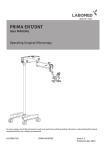
Back
www.furuno.co.jp
The paper used in this manual
is elemental chlorine free.
・FURUNO Authorized Distributor/Dealer
9-52 Ashihara-cho,
Nishinomiya, 662-8580, JAPAN
Telephone : +81-(0)798-65-2111
Fax
: +81-(0)798-65-4200
All rights reserved.
Printed in Japan
A : MAY 2007
C : SEP . 21, 2007
Pub. No. OME-44430-C
(TATA )
FA-30
*00016497012*
*00016497012*
* 0 0 0 1 6 4 9 7 0 1 2 *
IMPORTANT NOTICES
• The descriptions in this manual are intended for readers with a solid knowledge of English.
• No part of this manual may be copied or reproduced without written permission.
• If this manual is lost or worn, contact your dealer about replacement.
• The contents of this manual and equipment specifications are subject to change without notice.
• The example screens (or illustrations) shown in this manual may not match the screens you
see on your display. The screen you see depends on your system configuration and equipment
settings.
• Store this manual in a convenient place for future reference.
• FURUNO will assume no responsibility for the damage caused by improper use or modification
of the equipment (including software) by an unauthorized agent or a third party.
• When it is time to discard this product it must be done according to local regulations for disposal of industrial waste. For disposal in the USA, refer to the Electronics Industries Alliance
(http://www.eiae.org/).
i
SAFETY INSTRUCTIONS
The operator and installer must read the applicable safety instructions before attempting to
install or operate the equipment.
WARNING
Indicates a potentially hazardous situation which, if not avoided,
could result in death or serious injury.
CAUTION
Indicates a potentially hazardous situation which, if not avoided,
can result in minor or moderate injury.
Warning, Caution
Mandatory Action
Prohibitive Action
Safety instructions for the operator
WARNING
WARNING
Do not open the equipment.
Do not place liquid-filled containers on
the top of the equipment.
Only qualified personnel should work
inside the equipment.
Fire or electrical shock can result if a
liquid spills into the equipment.
Do not disassemble or modify the
equipment.
Make sure no rain or water splash
leaks into the equipment.
Fire, electrical shock or serious injury can
result.
Fire or electrical shock can result if water
leaks into the equipment.
Immediately turn off the power at the
power source if
water leaks into the equipment
something is dropped into the
equipment
the equipment is emitting smoke or
is on fire
the equipment is emitting strange
noises
Warning labels are attached to the equipment.
Do not remove these labels. If a label is missing
or illegible, contact a FURUNO agent or dealer
.
about replacement.
WARNING
WARNING
Name: Warning Label (1)
To avoid electrical shock, Type: 86-003-1011-1
do not remove cover. No
user-serviceable parts Code No.: 100-236-231
Continued use of the equipment can
cause fire or electrical shock. Contact a
FURUNO dealer or agent for service.
Do not operate the equipment with wet
hands.
WARNING
To avoid electrical shock,
do not remove cover.
No user-serviceable parts
inside.
Electrical shock can result.
Use the proper fuse.
Use of the wrong fuse can cause fire
or electrical shock.
ii
Name: Warning Label (2)
Type: 86-129-1001-1
Code No.: 100-236-741
Safety instructions for the installer
CAUTION
WARNING
Observe the following compass safe
distances to prevent interference to a
magnetic compass:
Turn off the power at the switchboard
before beginning the installation.
Fire or electrical shock can result if the
power is left on.
Standard
compass
Do not install the equipment where it
may get wet from rain or water splash.
FA-30
Water in the equipment can result in fire,
electrical shock or damage to the equipment.
Be sure that the power supply is
compatible with the voltage rating of the
equipment.
Connecting an incompatible power supply
can cause fire or damage the equipment.
The voltage rating appears on the inlet
of power.
iii
0.30 m
Steering
compass
0.30 m
TABLE OF CONTENTS
FOREWORD .........................................................................................................v
SYSTEM CONFIGURATION................................................................................vi
1. INSTALLATION ................................................................................................1
1.1 Equipment Lists ..................................................................................................................1
1.2 AIS Receiver FA-30 ............................................................................................................ 2
1.3 Whip Antenna ..................................................................................................................... 3
1.4 Wiring .................................................................................................................................4
2. WEB SOFTWARE SETUP, DATA DISPLAYS .................................................6
2.1 AIS Receiver FA-30 ............................................................................................................ 6
2.2 COM Port Setup, Network Setup........................................................................................7
2.3 Own Vessel Data Display, Channel Selection ..................................................................10
2.4 Sensor Status ................................................................................................................... 12
3. MAINTENANCE, TROUBLESHOOTING........................................................13
3.1 Maintenance ..................................................................................................................... 13
3.2 Replacing the Fuse...........................................................................................................14
3.3 Troubleshooting ................................................................................................................14
3.4 Diagnostics .......................................................................................................................15
Appendix 1: VHF CHANNEL LIST.................................................................AP-1
Appendix 2: MOUNTING VHF SPLITTER .....................................................AP-2
SPECIFICATIONS...........................................................................................SP-1
OUTLINE DRAWINGS ...................................................................................... D-1
INTERCONNECTION DIAGRAM...................................................................... S-1
iv
FOREWORD
A Word to the Owner of the FA-30
Congratulations on your choice of the FURUNO FA-30 AIS Receiver. We are confident you will see why the FURUNO name has become synonymous with quality and
reliability.
For over 50 years FURUNO Electric Company has enjoyed an enviable reputation for
quality marine electronics equipment. This dedication to excellence is furthered by our
extensive global network of agents and dealers.
This equipment is designed and constructed to meet the rigorous demands of the marine environment. However, no machine can perform its intended function unless operated and maintained properly. Please carefully read and follow the recommended
procedures for operation and maintenance.
Thank you for considering and purchasing FURUNO equipment.
Features
The FA-30 is a compact and cost effective AIS Receiver that is designed specifically
for small commercial, leisure and fishing boats.
Connected to a VHF antenna it receives AIS data from AIS-equipped vessels, shore
stations and navigational aids (AIS-equipped buoys, etc.). Vessel movement is plotted
on a display connected to the LAN port. Data includes identity (name, call sign and
MMSI), position, speed, heading, etc. of AIS-equipped vessels within VHF range.
Program Version
Item
Program No.
FA-30 AIS Receiver Main Program
0550227
v
Version No.
01.02
Date
May 2007
SYSTEM CONFIGURATION
WHIP ANTENNA
AIS RECEIVER
FA-30
PC
w/FAISPC MX
HUB
EXTERNAL
DISPLAY
EXTERNAL
DISPLAY
NAVNET
NAVNET
RADAR
CHART PLOTTER
ECDIS
PILOT PLUG
OR
SENSOR
GPS
SPEED LOG
GYROCOMPASS
SATELLITE COMPASS
OR
12-24 VDC
IF-1500AIS
: Standard supply
: Optional supply
: Local supply
vi
FR-8xx2 SERIES
1.
INSTALLATION
1.1
Equipment Lists
Standard supply
Name
Type
Code No.
Qty
-
1
Remarks
AIS Receiver
FA-30
Installation Materials
CP05-11101
001-014-160
1 set
Tapping screw
(4x20, 4 pcs.)
AIS Viewer
FP05-05910
000-010-938
1 set
FAISPC-MX for PC
Spare Parts
SP05-05701
001-014-150
1 set
2A fuse, 2 pcs.
Code No.
Qty
Remarks
150M-W2VN
000-113-498
1
P5E-4PTX-BL
000-164-634-10
Optional supply
Name
VHF Antenna
Type
2 m, RJ45-RJ45
1
LAN Cable
VHF Splitter
P5E-4PTX-BL
000-164-637-10
10 m, RJ45-RJ45
MJ-A6SPF0017-010C
000-159-704-11
1 m, RJ45-MJ6
MJ-A6SPF0017-050C
000-159-705-11
5 m, RJ45-MJ6
MJ-A6SPF0017-100C
000-159-706-11
MJ-A6SPF0017-200C
000-159-707-11
20 m, RJ45-MJ6
MJ-A6SPF0017-300C
000-159-708-11
30 m, RJ45-MJ6
OP05-106
000-011-704
1
1
1
10 m, RJ45-MJ6
AIS Receiver FA-30
Mounting considerations, mounting
The FA-30 can be mounted on a desktop, deck or on a bulkhead. When selecting a
mounting location, keep the following points in mind:
• The temperature and humidity should be moderate and stable.
• Locate the unit away from exhaust pipes and vents.
• The mounting location should be well ventilated.
• Mount the unit where shock and vibration are minimal.
• Keep the unit away from electromagnetic field-generating equipment such as
motors and generators.
• A magnetic compass will be affected if the FA-30 is placed too close to it. Observe
the compass safe distances noted in the safety instructions to prevent disturbance
to the magnetic compass.
• Fix the unit to the mounting location with 4x20 self-tapping screws (supplied).
"A" DETAIL
MORE THAN
70
MORE THAN
70
MORE THAN 150
1.2
All dimensions
in millimeters.
2
1.3
Whip Antenna
Location
The location of the AIS VHF-antenna should be carefully considered. Digital communication is more sensitive than analog/voice communication to interference created by
reflections in obstructions like masts and booms. It may be necessary to relocate the
VHF radiotelephone antenna to minimize interference effects. To minimize interference effects, the following guidelines apply:
• The AIS VHF antenna should be placed in an elevated position that is as free as
possible with a minimum of 0.5 meters in the horizontal direction from constructions
made of conductive materials. The antenna should not be installed close to any
large vertical obstruction. The objective for the AIS VHF antenna is to see the horizon freely through 360 degrees.
• There should not be more than one antenna on the same plane. The AIS VHF
antenna should be mounted directly above or below the ship’s primary VHF radiotelephone antenna, with no horizontal separation and with a minimum of 2.8 meters
vertical separation. If it is located on the same plane as other antennas, the distance apart should be at least 10 meters.
• Install the VHF whip antenna (option) referring to the outline drawing at the back of
this manual. Separate this antenna from other VHF radiotelephone antennas as
shown below to prevent interference to the FA-30.
Whip antenna
for AIS
Other VHF
whip antenna
More than
2.8 m
More than 10 m
More than 0.5 m
Horizontal separation distance
Vertical separation distance
Cabling
• Use coaxial cable type 5D-2V or the equivalent.
• The cable should be kept as short as possible to minimize signal attenuation, and
the maximum length is 50 meters.
• All outdoor-installed connectors on coaxial cables should be fitted with preventive
isolation such as vulcanizing tape to protect against water penetration into the
antenna cable.
• Coaxial cables should be installed in separate signal cable channels/tubes and at
least 10 cm away from power supply cables. Crossing of cables should be done at
right angles (90 degrees). The minimum bend radius of the coaxial cable should be
5 times the cable's outer diameter.
3
1.4
Wiring
Connect power source, LAN cable, VHF antenna and ground wire as shown
below.
VHF WHIP
ANTENNA
(option)
COAXIAL CABLE 5D-2V
(local supply)
AIS RECEIVER
PC, HUB,
NAVNET
GROUND WIRE
IV-1.25sq
LAN CABLE
P5E-4PTX-BL
(2 m or 10 m)
NAVNET, SENSOR
POWER CABLE
(supplied)
RS-422 RATING
*2
*1
12-24 VDC
RED
+
-
GROUND
BLACK
Switchboard breaker
*1 Supply from breaker on switchboard.
*2 If COM lines (connection for NavNet, sensor) are not used, tape them to prevent
short circuit.
4
Attaching coaxial connector (M-P-5) to coaxial cable
The antenna cable (coaxial cable, type 5D-2V) is terminated at the FA-30 with an
M-P-5 coaxial connector. Attach the connector to the cable as shown below.
30 mm
7 mm
2
mm
Sheath
Braided
shield
Fasten tightly. Contact sleeve
Solder here.
Conductor
Cut conductor here.
Coupling
ring
Solder here.
Insulator
Connection of AIS viewer (FAISPC-MX)
The AIS viewer may be connected to the FA-30 directly, or to both FA-30 and NavNet vx2. See
the figure below for connection examples.
FA-30
RJ-45 to 6 Pin Cable
NavNetvx2 display unit
DIRECT CONNECTION
RJ-45 to 6 Pin Cable
FA-30
Standard Ethernet
"Straight Through"
Cable,
RJ-45 to RJ-45
NavNetvx2 display unit
HUB
NavNetvx2 display unit
LAN Cable (CAT5)
MaxSea AIS Viewer
NAVNETvx2/MAXSEA AIS VIEWER CONNECTION
5
2.
WEB SOFTWARE SETUP,
DATA DISPLAYS
2.1
AIS Receiver FA-30
The FA-30 has no power switch. Power is fed from the ship’s switchboard, and a power switch on the switchboard turns the FA-30 on or off. When powered, the PWR LED
(green) on the cover lights. The two other LEDs on the cover flash or light with equipment state. The ER LED (red) lights while the equipment is being initialized, and flashes when equipment error is found. The RX LED (orange) lights when receiving.
PWR (Power) LED
Lights (in green) when power is on.
ER (Error) LED
Flashes (in red) for RAM, ROM, RX1+RX2 error.
RX LED
Lights (in orange) 50 ms when channel RX1/RX2 is receiving.
6
2.2
COM Port Setup, Network Setup
The FA-30 is set up from the PC or external display. The procedure below shows how
to set up the COM/POWER and NETWORK ports from a PC.
NOTICE: Only one FA-30 may be connected to the network.
Start up
1. Start up the PC and enter IP address and subnet mask.
1)
2)
3)
4)
Right-click My Network and Properties.
Right-click Local Area Network and Properties.
Select Internet Protocol and Properties.
Enter IP address 172.31.24.xxx (xxx=any three digits from 001 to 254, except
002).
5) Enter subnet mask 255.255.0.0.
2. Open Internet Explorer and do the following:
1)
2)
3)
4)
Click Tools on the menu bar.
Click Internet Options.
The General tab is selected. Click Settings at Temporary Internet Files.
Click the radio button “Every visit to the page” at “Check for newer versions of
stored page”.
5) Click the OK button.
6) Click the OK button again.
3. Enter URL as http://172.31.24.2 and press the Enter key.
4. Click Port Setup to show the Port Setup menu.
7
COM port setup
5. Click COM PORT Setup to show the COM Port Setup menu.
(default=IEC61162)
6. The default setting for Data Type is IEC61162, which is suitable for most installations. If change is necessary, click the Data Type drop-down list and choose data
type as applicable, among the following choices.
IEC61162: Transmit and receive IEC61162 format data via COM port. (P sentences are received but not transmitted.)
IEC61162+ P-sentence: Transmit and receive IEC61162+P sentences format
data via COM port.
Off: FA-30 transmits no data.
With the radio buttons at RX Speed, choose how RX speed is regulated, Auto or
Manual. For manual, choose speed from the drop-down list.
Note: Tx speed is fixed at 38400 bps.
7. Click OK to confirm setting.
8. Click "<<Port Setup" to return to the Port Setup menu.
8
NETWORK setup
9. Click Network Setup to show the Network Setup menu.
(default=172.031.024.002)
172.031.024.002
255.255.000.000
000.000.000.000
10.Enter the IP address assigned to the FA-30.
11.Enter subnet mask for the network.
12.Enter gateway address.
13.For NavNet connection, enter NavNet port number at NavNet Port Number. Enter
ten-thousandths and one-thousandths places.
14.At Host Name, enter host name to be used in NavNet, AIS0 - AIS9.
15. At AIS Data Output, select how to output AIS data.
Auto: Auto-detect of where to output AIS data.
Continuous: Output data continuously. Select if interfaced with FAISPC_MX.
Note: It is not necessary to change the settings of NavNet Port Number, Host
Name and AIS Data Output. Connection is available without adjusting them.
16.Click the OK button to finish.
17.If you changed a setting, the message below appears.
You must restart your FA-30
before the new settings take effect.
Do you want to restart your FA-30 now?
(It will take about 1 minute to restart your FA-30).
18.Click the Yes button to restart. "ER" LED on the FA-30 lights. After the LED goes
off access is given.
19.The message “Please close the window.” appears. Close the browser.
After restart is completed, it is necessary to access the FA-30 using new values. For
example, if you changed the IP address, use the new address to access the FA-30.
9
2.3
Own Vessel Data Display, Channel Selection
The Own Vessel Data display shows your ship’s MMSI no., RX channel nos., and
channel selection method.
1. Show the main menu, referring to section 2.2.
2. Click Own Vessel Data.
CH. 2087 (International)
CH. 2088 (International)
Description of own vessel data
MMSI: MMSI number (nine-digit number).
RX1: Channel (four digits) received over RX1. Channel type (International, Local) is
shown in parentheses.
RX2: Channel (four digits) received over RX2. Channel type (International, Local) is
shown in parentheses.
Channel Selection: Current channel selection method, Auto or Manual, is shown. For
how to change channels, go to the next step.
3. Click the Edit button to show the Channel menu.
4. Enter channel no. (four digits) at RX1 and RX2.
10
5. Click the RX Mode drop-down list to choose which channel(s) to receive.
RX 1+2
RX 1+2
RX 1
RX 2
RX 1+2: Receive via channels 1 and 2.
RX 1: Receive via channel 1.
RX 2: Receive via channel 2.
6. Click the Channel Selection drop-down list.
7. Choose Manual.
8. Click the OK button to finish. The Own Vessel Data menu appears.
To return to automatic channel selection, open the Channel menu, choose Auto at
Channel Selection and click the OK button. CH2087 and CH2088 are automatically
selected.
11
2.4
Sensor Status
The sensor status display provides information about sensors connected to the FA-30.
1. Show the main menu, referring to section 2.2.
2. Click Sensor Status. The illustration below shows typical sensor status indications.
GPS in use
Heading valid
Channel Management Parameters Changed
Description of sensor status indications
Indication
Meaning
Remarks
DGPS in use
DGPS currently in use
See *1
GPS in use
GPS currently in use
See *1
SOG/COG in use
SOG/COG currently in use
Heading valid
Valid heading data
Channel Management
Parameters Changed
Channel parameters have been changed.
See *2
*1 Whichever navigator is in use.
*2 Displayed for 30 seconds after changing channel parameters. (It is necessary to
update the display.)
12
3.
MAINTENANCE,
TROUBLESHOOTING
WARNING
NOTICE
Do not open the equipment
unless totally familiar with
electrical circuits and
service manual.
Do not apply paint, anti-corrosive
sealant or contact spray to coating or
plastic parts of the equipment.
Those items contain organic solvents that
can damage coating and plastic parts,
especially plastic connectors.
Only qualified personnel
should work inside the
equipment.
3.1
Maintenance
Regular maintenance helps maintain good performance. Check the items listed below at least
monthly to help keep your equipment in good working order.
Maintenance table
Item
Check point, remedy
Wiring
Check that each cable and wire are securely fastened.
Refasten if necessary.
Ground
Check ground point for rust. Clean if necessary.
VHF antenna
Check VHF antenna and its cabling for damage.
Replace if necessary.
Cabinet
Dust and dirt should be removed from the cabinet with a soft, dry
cloth. Do not use chemical-based cleaners; they can remove
paint and markings.
13
3.2
Replacing the Fuse
The fuse (2A) inside the FA-30 protects it from overcurrent and equipment fault. If the
unit cannot be powered, that is, the PWR (power) LED is off, the fuse may have blown.
If this happens, turn off the power to the FA-30, open the cover and check the fuse. If
the fuse has blown, find out the reason before replacing it. If it blows again after replacement, contact a FURUNO agent or dealer for advice.
Part
Type
Fuse (2A)
Code No.
FGMB AC125V 2A PBF
000-157-479-10
WARNING
Use the proper fuse.
Use of a wrong fuse can result in damage
to the equipment and cause fire.
3.3
Troubleshooting
The troubleshooting table below provides typical operating problems and the means
to restore normal operation. If you cannot restore normal operation, do not attempt to
check inside the receiver; there are no user serviceable parts inside the receiver.
Troubleshooting table
Symptom
Problem
Remedy
Receiver cannot be
powered.
Fuse inside the receiver may
have blown.
Cannot receive.
• Check if the antenna is firmly
• VHF antenna may have
fastened.
loosened.
• Antenna or its cabling may be • Check the antenna and its
cabling for damage.
damaged.
• Rx channel is malfunctioning. • Confirm the channel setting.
14
Replace the fuse.
3.4
Diagnostics
The built-in diagnostic facility displays program version no. and checks RAM, ROM
and RX channels for proper operation.
1. Open Internet Explorer and show the main menu.
2. Click Test to show the Test display.
0550227-xx.xx*
*xx.xx is program version.
The program version number appears on the first line. The CPU1 RAM and CPU2
RAM, ROM and the two RX channels are checked for proper operation, and the results are displayed as OK or NG (No Good). For any NG, try resetting the power and
checking connections. If NG condition persists, contact your dealer for advice.
15
Appendix 1: VHF CHANNEL LIST
Ch No.
1001
1002
1003
1004
1005
6
1007
1018
1019
1020
1021
1022
1023
1024
1025
1026
1027
1028
1060
1061
1062
1063
1064
1065
1066
67
68
69
70
71
72
73
74
75
76
77
1078
1079
1080
1081
1082
1083
1084
1085
1086
1087
Frequency
156.05
156.1
156.15
156.2
156.25
156.3
156.35
156.9
156.95
157
157.05
157.1
157.15
157.2
157.25
157.3
157.35
157.4
156.025
156.075
156.125
156.175
156.225
156.275
156.325
156.375
156.425
156.475
156.525
156.575
156.625
156.675
156.725
156.775
156.825
156.875
156.925
156.975
157.025
157.075
157.125
157.175
157.225
157.275
157.325
157.375
Ch No.
1088
1201
1202
1203
1204
1205
1206
1207
208
209
210
211
212
213
214
215
216
217
1218
1219
1220
1221
1222
1223
1224
1225
1226
1227
1228
1260
1261
1262
1263
1264
1265
1266
267
268
269
270
271
272
273
274
275
276
Frequency
157.425
156.0625
156.1125
156.1625
156.2125
156.2625
156.3125
156.3625
156.4125
156.4625
156.5125
156.5625
156.6125
156.6625
156.7125
156.7625
156.8125
156.8625
156.9125
156.9625
157.0125
157.0625
157.1125
157.1625
157.2125
157.2625
157.3125
157.3625
157.4125
156.0375
156.0875
156.1375
156.1875
156.2375
156.2875
156.3375
156.3875
156.4375
156.4875
156.5375
156.5875
156.6375
156.6875
156.7375
156.7875
156.8375
Ch No.
277
1278
1279
1280
1281
1282
1283
1284
1285
1286
1287
2001
2002
2003
2004
2005
2007
8
9
10
11
12
13
14
15
16
17
2018
2019
2020
2021
2022
2023
2024
2025
2026
2027
2028
2060
2061
2062
2063
2064
2065
2066
2078
AP-1
Frequency
156.8875
156.9375
156.9875
157.0375
157.0875
1571375
157.1875
157.2375
157.2875
157.3375
157.3875
160.65
160.7
160.75
160.8
160.85
160.95
156.4
156.45
156.5
156.55
156.6
156.65
156.7
156.75
156.8
156.85
161.5
161.55
161.6
161.65
161.7
161.75
161.8
161.85
161.9
161.95
162
160.625
160.675
160.725
160.775
160.825
160.875
160.925
161.525
Ch No.
2079
2080
2081
2082
2083
2084
2085
2086
2087
2088
2201
2202
2203
2204
2205
2206
2207
2218
2219
2220
2221
2222
2223
2224
2225
2226
2227
2228
2260
2261
2262
2263
2264
2265
2266
2278
2279
2280
2281
2282
2283
2284
2285
2286
2287
Frequency
161.575
161.625
161.675
161.725
161.775
161.825
161.875
161.925
161.975
162.025
160.6625
160.7125
160.7625
160.8125
160.8625
160.9125
160.9625
161.5125
161.5625
161.6125
161.6625
161.7125
161.7625
161.8125
161.8625
161.9125
161.9625
162.0125
160.6375
160.6875
160.7375
160.7875
160.8375
160.8875
160.9375
161.5375
161.5875
161.6375
161.6875
161.7375
161.7875
161.8375
161.8875
161.9375
161.9875
Appendix 2: MOUNTING VHF SPLITTER
The VHF splitter enables the AIS receiver and VHF transceiver to share a single VHF antenna.
Note: The FA-30 can not receive AIS signal when the VHF transceiver is transmitting.
Equipment Lists
VHF Splitter: Type OP05-106, Code No. 000-011-704
No.
Name
Type
Code No.
Qty
Remarks
1
VHF Splitter Assembly
OP05-106-1
001-024-100
1
Rear panel + pcb 05P0817
2
Installation Materials
CP05-11301
001-024-110
1
Cable tie CV-70N, 1 pc.
Mounting procedure
1. Open the detachable cover.
1. Put fingers on both sides and
pull outwards and lift up to
take off.
View
2. Unfasten four screws to separate the
chassis from the mounting plate.
Side View
2. Unfasten
four
screws.
3. Disconnect plugs on J7, J12 and the
ground wire from pcb 05P0807 .
3. Disconnect.
AP-2
Ground wire
4. Turn over the chassis. Then, disconnect mini coaxial wire from J2 on pcb 05P0808A.
05P8080A
Hole
4. Disconnect mini coaxial wire.
Bottom view
5. Unfasten four screws from the rear panel to come free.
5. Unfasten four screws.
Rear panel
6. Pull out the cable assembly from the rear panel. (The rear panel may be dicarded.)
6. Push strongly here and pull out the cable.
7. Pass the cable assembly to the new rear panel.
8. Connect the plugs and ground wires to original places.
9. Pass two wires (two-core power cable and mini coaxial cable) from pcb 05P0817 on the new
rear panel through the hole on the chassis.
Pass two-core power cable and then mini coaxial cable.
10.Fix the new rear panel to the chassis with original four screws.
AP-3
11.Connect the plug of mini coaxial
wire to J2 on pcb 05P0808A.
12.Connect two-core power cable to
J3 on pcb 05P0808B.
05P0808A
05P0808B
J3
13.Tie two cables with a cable tie.
12. Connect two-core
power cable.
13. Tie cables
11. Connect
with cable
mini coaxial
tie.
wire.
Hole
Bottom view of the chassis
14.Reassemble the chassis.
15.Connect the coaxial cable from the VHF antenna to the ANT port.
16.Connect the coaxial cable from the VHF transceiver to the VHF port.
Note: The wrong connection of coaxial cable from VHF antenna or VHF transceiver may
damage this equipment.
VHF antenna
FA-30
J2
J1
ANT
05P0808A
J1
05P0187
J1
J2
05P0808B
VHF
12V
0V
J3
AP-4
VHF transceiver
FURUNO
FA-30
SPECIFICATIONS OF AIS RECEIVER
FA-30
1.
GENERAL
1.1
Rx Capacity
2250 reports/minute, 1 channel
4500 reports/minute, 2 channels
1.2
Rx System
TDMA dual wave simultaneous reception
1.3
Frequency Switching
Automatic (external device)
1.4
Complying Regulations
IEC 60945 Ed. 4, and receiver section conforms to IEC 61993-2,
IEC 62287-1, ITU-R M.1371-1,
2.
AIS RECEIVER (RX1/RX2)
2.1
Rx Frequency Range
156.025 MHz to 162.025 MHz
2.2
Channel Interval
25 kHz/12.5 kHz
2.3
Oscillator Frequency
1st local oscillator f+(51.136 MHz/51.236 MHz)
2nd local oscillator 51.1 MHz/51.2 MHz
2.4
Intermediate Frequency 1st IF 51.136 MHz/51.236 MHz
2nd IF 36 kHz
2.5
Rx System
Double superheterodyne
2.6
Sensitivity
-107 dBm (PER less than 20%)
2.7
Error Characteristics
-77 dBm (PER less than 2%)
-7 dBm (PER less than 10%)
2.8
Channel Rej.
Better than -10 db
2.9
Adjacent Channel Rej.
Better than 70 dB (±25 kHz)
2.10 Spurious Response
Better than 70 dB (50 MHz – 520 MHz)
2.11 Mutual Modulation
Wanted freq. f – 101 dBm
Characteristic
Unwanted freq. f ±50 kHz, no modulation –36 dBm
f ±100 kHz, 400 Hz/±3 kHz modulation –36 dBm
PER less than 20%
2.12 Sensitivity Suppression
Wanted freq. f –101 dBm
Unwanted freq. f ±500 kHz, ±1 MHz, ±2MHz,
no modulation –23 dBm
Unwanted freq. f ±5 MHz, ±10 MHz, no modulation –15 dB
PER less than 20%
2.13 Spurious Emission
9 kHz – 1 GHz less than –57 dBm
1 GHz – 4 GHz less than –47 dBm
SP-1
E4443S01A
FURUNO
3.
INTERFACE
3.1
COM port
FA-30
Input: RS422(38.4kbps)/IEC61162-1(4800 bps)
Output: RS422(38.4kbps)
Input sentences: ACK, ACA, DTM, GBS, GGA, GLL, GNS, HDT,
OSD, RMC, VBW, VTG, DSC, DSE, AIQ, ZDA, PFEC, ABM*,
BBM*, AIR*
Output sentences: ACA, ACS, ALR, VDM, VDO, TXT, ABK*, PFEC
3.2
NETWORK
Ethernet 10/100BASE-T
Input sentences: ACK, ACA, DTM, GBS, GGA, GLL, GNS, HDT,
OSD, RMC, VBW, VTG, DSC, DSE, AIQ, ZDA, PFEC, ABM*,
BBM*, AIR*
Output sentences: ACA, ACS, ALR, VDM, VDO, TXT, ABK*, PFEC
* ABK sentence sent in response to mis-input of ABM, BBM, AIR.
4.
ANTENNA
50 ohm single dipole antenna
5.
POWER SUPPLY
12-24 VDC: 1.2-0.6 A
6.
ENVIRONMENTAL CONDITION
6.1 Ambient Temperature
-15°C to +55°C
6.2 Relative Humidity
93% at 40°C
6.3 Waterproofing (IEC 60529) IP20
6.4 Vibration (IEC 60945 ed.4)
- 2Hz to 5 Hz and up to 13.2 Hz with an excursion of ±1 mm ±10%
(7m/s2 maximum acceleration at 13.2 Hz )
- above 13.2 Hz and up to 100 Hz with a constant maximum
acceleration of 7 m/s2
7.
COATING COLOR
N2.5
SP-2
E4443S01A
D-1
D-2
Nov.28'03
C
B
A
2
3
4
5
6
7
8
2m
シロ
アオ
キ
ミドリ
チャ
WHT
BLU
YEL
GRN
BRN
アカ RED
クロ BLK
P
P P
RJ45
NOTE
*1: SHIPYARD SUPPLY.
*2: OPTION.
*3: USE STRAIGHT LAN CABLE WHEN A HUB W/O AUTO MDI/MDI-X FUNCTION IS USED.
*4: IF COM LINES ARE NOT USED, TAPE THEM TO PREVENT SHORT-CIRCUIT.
注 記
*1)造船所手配。
*2)オプション。
*3)Auto MDI/MDI-X対応でないHUBのときは、ストレートケーブルを使用する。
*4)COMラインを使用しないときは、芯線がショートしないようテープで絶縁する。
*2
NAVNET2
NETWORK MJ-A6SPF MJ-A6SPF0017-010C/
050C/100C/200C/300C
関連機器
E_TD_P 1
1/5/10/20/30m,φ6
NAVNET2
E_TD_N 2
EQUIPMENT
E_RD_P 3
E_RD_N 4
NC 5
SHIELD 6
TX_N
*1 RJ45
RX_P
外部表示器
LAN CABLE (CAT5)
NC
EXTERNAL DISPLAY
NC
RX_N
NC
(AUTO MDI/MDI-X) NC
PC
*4
2
スイッチングハブ
*2 *3
SWITCHING HUB
RJ45
P5E-4PTX-BL,2/10m
TX_P 1
HUB-100
P
1
2
3
4
5
(-)
12-24VDC (+)
外部表示器、センサー
IF-1500AIS
EXT. DISPLAY/SENSOR
(RS-422/IEC61162-1)
*1 RJ45
LAN CABLE (CAT5)
1
1
2
3
4
5
6
7
8
P
P
& PWR
05P0807
MASS
S.Hori
T.TAKENO
kg
T.YAMASAKI
*1
5D-2V,MAX.50m
*1
M-P-5
J1
VHF
J2
ANT
05-096-2002-1
*2
VHFスプリッター
VHF SPLITTER
OP05-106
FA-30
NAME
名 称
VHF送受信機
VHF TRANSCEIVER
AIS RECEIVER
INTERCONNECTION DIAGRAM
AIS受信機
相互結線図
FA-30
*1
COAX. CABLE(50Ω)
*1
5D-2V,MAX.50m
TYPE
*1
M-P-5
*1
M-P-5
*1
M-P-5
ホイップアンテナ
WHIP ANTENNA
FAB-151D(JAPAN ONLY)
150M-W2VN *2
4
VHFスプリッター(オプション)使用時
VHF SPLITTER (OPTION) INSTALLATION
*1
M-P-5
REF.No.
VHF ANT
J1
C4443-C01- E
Sep. 14 '07
DWG.No.
SCALE
Sep. 10 '07
CHECKED
Sep. 10 '07
APPROVED
DRAWN
GND *1
IV-1.25sq.
J1
E_TD_P
E_TD_N
E_RD_P
NC
NC
E_RD_N
NC
MAIN
NC
NETWORK
1
2
J12
DC_P(+)
DC_M(-)
J7
1 COM_TD-A
2 COM_TD-B
3 COM_RD-A
4 COM_RD-B
5 0V
COM/POWER
AIS受信機
AIS RECEIVER
FA-30
3
S-1
FURUNO ELECTRIC CO., LTD.
9-52 Ashihara-Cho, Nishinomiya City, 662-8580, Hyogo, Japan
Tel: +81 798-65-2111 Fax: +81 798-65-4200
Pub NO. DOC-929
Declaration of Conformity
We
FURUNO ELECTRIC CO., LTD.
-----------------------------------------------------------------------------------------------------------------(Manufacturer)
9-52 Ashihara-Cho, Nishinomiya City, 662-8580, Hyogo, Japan
------------------------------------------------------------------------------------------------------------------(Address)
declare under our sole responsibility that the product
AIS receiver Type: FA-30 with optional VHF Splitter kit
-----------------------------------------------------------------------------------------------------------------(Model name, serial number)
is in conformity with the essential requirements as described in Article 10.3 and Annex II of the
Directive 1999/5/EC of the European Parliament and of the Council of 9 March 1999 on radio
equipment and telecommunications terminal equipment (R&TTE Directive) and satisfies all the
technical regulations applicable to the product within this Directive
IEC 60945 Third edition: 1996-11 Subclause 10.2
IEC 60945 Fourth edition: 2002-08 Subclauses 8.2.2, 8.3.1, 8.4.2, 8.7, 9.2, 9.3, 10.3 to 10.9, 12.1
to 12.4
IEC 62287-1 First edition: 2006-03 Subclauses 10.2.1.2, 11.2.1, 11.3 (methods of test only)
IEC 61993-2 First edition: 2001-12 Subclause 15.3.1 (method of test only)
IEC 60950-1 First edition: 2001-10
------------------------------------------------------------------------------------------------------------------(title and/or number and date of issue of the standard(s) or other normative document(s))
For assessment, see
•
EMC Test Report FLI 12-07-008 of 23 March 2007 issued by Furuno Labotech International
Co., Ltd, Japan
•
Test Report (Climatic & Vibration) FLI 12-07-007 of 15 March 2007 issued by Furuno Labotech
International Co., Ltd. Japan
•
Safety Test Report FLI 12-07-009 of 19 March 2007 issued by Furuno Labotech International
Co., Ltd. Japan
On behalf of Furuno Electric Co., Ltd.
Nishinomiya City, Japan
March 27, 2007
Hiroaki Komatsu
Manager,
International Rules and Regulations
(Place and date of issue)
(name and signature or equivalent marking of authorized person)
---------------------------------------------------
----------------------------------------------------------------