1
OPERATOR'S MANUAL
Model
www.furuno.com
(Elemental Chlorine Free)
The paper used in this manual
is elemental chlorine free.
FURUNO Authorized Distributor/Dealer
9-52, Ashihara-cho,
Nishinomiya, 662-8580, JAPAN
All rights reserved.
Printed in Japan
A: MAR. 2008
F2: JUL. 23, 2014
Pub. No. OME-44420-F2
(YOTA) FA-50
00016841415
IMPORTANT NOTICES
General
• The operator of this equipment must read and follow the descriptions in this manual. Wrong operation or maintenance can cancel the warranty or cause injury.
• Do not copy any part of this manual without written permission from FURUNO.
• If this manual is lost or worn, contact your dealer about replacement.
• The contents of this manual and equipment specifications can change without notice.
• The example screens (or illustrations) shown in this manual can be different from the screens
you see on your display. The screens you see depend on your system configuration and equipment settings.
• Save this manual for future reference.
• Any modification of the equipment (including software) by persons not authorized by FURUNO
will cancel the warranty.
• All brand and product names are trademarks, registered trademarks or service marks of their
respective holders.
• Windows and Windows Vista are either registered trademarks or trademarks of Microsoft Corporation of the United States or other countries.
How to discard this product
Discard this product according to local regulations for the disposal of industrial waste. For disposal
in the USA, see the homepage of the Electronics Industries Alliance (http://www.eiae.org/) for the
correct method of disposal.
How to discard a used battery
Some FURUNO products have a battery(ies). To see if your product has a battery(ies), see the
chapter on Maintenance. Follow the instructions below if a battery(ies) is used. Tape the + and terminals of battery before disposal to prevent fire, heat generation caused by short circuit.
In the European Union
The crossed-out trash can symbol indicates that all types of batteries
must not be discarded in standard trash, or at a trash site. Take the
used batteries to a battery collection site according to your national
legislation and the Batteries Directive 2006/66/EU.
Cd
In the USA
The Mobius loop symbol (three chasing arrows) indicates that Ni-Cd
and lead-acid rechargeable batteries must be recycled. Take the used
batteries to a battery collection site according to local laws.
In the other countries
Ni-Cd
Pb
There are no international standards for the battery recycle symbol. The number of symbols can
increase when the other countries make their own recycle symbols in the future.
i
SAFETY INSTRUCTIONS
The operator and installer must read the applicable safety instructions before attempting to install
or operate the equipment.
WARNING
Indicates a potentially hazardous situation which, if not avoided,
could result in death or serious injury.
CAUTION
Indicates a potentially hazardous situation which, if not avoided,
can result in minor or moderate injury.
Warning, Caution
Mandatory Action
Prohibitive Action
Safety instructions for the operator
WARNING
Do not open the shield cover.
Only qualified personnel should work
inside the equipment.
Do not disassemble or modify the
equipment.
Fire, electrical shock or serious injury can
result.
Immediately turn off the power at the
power source if
water leaks into the equipment
something is dropped into the
equipment
the equipment is emitting smoke or
is on fire
the equipment is emitting strange
noises
WARNING
Continued use of the equipment can
cause fire or electrical shock. Contact a
FURUNO dealer or agent for service.
Do not operate the equipment with wet
hands.
Electrical shock can result.
Use the proper fuse.
Use of the wrong fuse can cause fire
or electrical shock.
ii
WARNING
Do not place liquid-filled containers on
the top of the equipment.
Fire or electrical shock can result if a
liquid spills into the equipment.
Make sure no rain or water splash
leaks into the equipment.
Fire or electrical shock can result if water
leaks into the equipment.
Warning labels are attached to the equipment.
Do not remove these labels. If a label is missing
or illegible, contact a FURUNO agent or dealer
replacement.
WARNING
Name: Warning Label (1)
To avoid electrical shock, do Type: 86-003-1011-1
not remove cover. No userCode No.: 100-236-232-10
serviceable parts inside.
WARNING
To avoid electrical shock,
do not remove cover.
No user-serviceable parts
inside.
Name: Warning Label (2)
Type: 86-129-1001-1
Code No.: 100-236-742-10
SAFETY INSTRUCTIONS
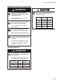
Safety instructions for the installer
CAUTION
WARNING
ELECTRICAL SHOCK HAZARD
Do not open the equipment unless
totally familiar with electrical circuits
and service manual.
Observe the following compass safe
distances to prevent interference to a
magnetic compass:
Standard
compass
Only qualified personnel should work
inside the equipment.
Turn off the power at the switchboard
before beginning the installation.
Fire or electrical shock can result if the
power is left on.
Steering
compass
FA-50
0.30 m
0.30 m
PR-240
0.90 m
0.60 m
GVA-100-T
0.30 m
0.30 m
DB-1
0.30 m
0.30 m
Do not install the equipment where it
may get wet from rain or water splash.
Water in the equipment can result in fire,
electrical shock or damage to the equipment.
Be sure that the power supply is
compatible with the voltage rating of the
equipment.
Connecting an incompatible power supply
can cause fire or damage the equipment.
The voltage rating appears on the inlet
of power.
Radiation Hazard
WARNING
Do not approach the antenna closer
than 0.4 m (MPE by FCC) when it is
transmitting.
The antenna emits radio waves which
can be harmful to the human body.
RF power density
on antenna aperture
2
100 W/m
2
10 W/m
2
2 W/m
Distance
Description
required by
Nil
0.1 m
0.4 m
IEC 60945
IEC 60945
MPE by FCC
(MPE: Minimum Permissible Exposure)
iii
TABLE OF CONTENTS
FOREWORD ....................................................................................................................v
SYSTEM CONFIGURATIONS .......................................................................................vii
1.
INSTALLATION .....................................................................................................1-1
1.1
1.2
1.3
1.4
1.5
1.6
1.7
1.8
2.
OPERATION ..........................................................................................................2-1
2.1
2.2
2.3
2.4
2.5
2.6
2.7
3.
Equipment List ........................................................................................................... 1-1
AIS Transponder FA-50 ............................................................................................. 1-3
VHF Antenna.............................................................................................................. 1-3
GPS Antenna ............................................................................................................. 1-5
GPS/VHF Combined Antenna.................................................................................... 1-7
AC-DC Power Supply (option) ................................................................................... 1-9
Wiring ....................................................................................................................... 1-10
Setting and Adjustments .......................................................................................... 1-12
1.8.1 COM PORT setup, Network sep .................................................................. 1-12
1.8.2 Ship static..................................................................................................... 1-15
AIS Transponder FA-50 ............................................................................................. 2-1
RX Message Log........................................................................................................ 2-2
Own Vessel Data Display........................................................................................... 2-3
Alarm Status............................................................................................................... 2-6
Sensor Status............................................................................................................. 2-7
TX Power ................................................................................................................... 2-7
Silent .......................................................................................................................... 2-8
MAINTENANCE, TROUBLESHOOTING...............................................................3-1
3.1
3.2
3.3
3.4
3.5
Maintenance............................................................................................................... 3-1
Replacing the Fuse .................................................................................................... 3-2
Troubleshooting ......................................................................................................... 3-2
Diagnostics................................................................................................................. 3-3
List of Terms .............................................................................................................. 3-4
APPENDIX 1 MENU TREE .......................................................................................AP-1
APPENDIX 2 VHF CHANNEL LISTS........................................................................AP-2
APPENDIX 3 PARTS LIST, LOCATIONS ................................................................AP-4
APPENDIX 4 DIGITAL INTERFACE.........................................................................AP-6
SPECIFICATIONS .....................................................................................................SP-1
PACKING LISTS.......................................................................................................... A-1
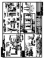
OUTLINE DRAWINGS................................................................................................. D-1
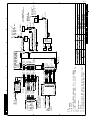
INTERCONNECTION DIAGRAM ................................................................................ S-1
INDEX.......................................................................................................................... IN-1
iv
FOREWORD
A Word to the Owner of the FA-50
Congratulations on your choice of the FURUNO FA-50 AIS Transponder. We are confident you
will see why the FURUNO name has become synonymous with quality and reliability.
Since 1948, FURUNO Electric Company has enjoyed an enviable reputation for quality marine
electronics equipment. This dedication to excellence is furthered by our extensive global network
of agents and dealers.
This equipment is designed and constructed to meet the rigorous demands of the marine environment. However, no machine can perform its intended function unless operated and maintained
properly. Please carefully read and follow the recommended procedures for operation and maintenance.
Thank you for considering and purchasing FURUNO equipment.
Features
The FA-50 is a Class B AIS (Automatic Identification System) capable of exchanging navigation
and ship data between own ship and other ships or coastal stations. It complies with IMO MSC.
140(76) Annex 3, A.694, ITU-R M.1371-2 and DSC ITU-R M.825-3 It also complies with IEC
60945 (EMC and environmental conditions).
FA-50 consists of VHF and GPS antennas, a transponder unit and several associated units. The
transponder contains a VHF transmitter, two TDMA receivers on two parallel VHF channels, interface, communication processor, and internal GPS receiver. The internal GPS is a 12-channel allin-view receiver with a differential capability. It also gives position, COG and SOG when the external GPS. FA-50 receives DSC, time-sharing with TDMA receiver.
The main features are:
z Safety of navigation by automatically exchanging navigational data
z Static data
• MMSI (Maritime Mobile Service Identity)
• Call sign & Ship’s name
• Type of ship
• Location of position-fixing antenna on the ship
z Dynamic data
• Ship's position with accuracy indication and integrity status
• Universal Time Coordinated (UTC)
• Course over ground (COG)
• Speed over ground (SOG)
• Heading
z Voyage-related data
• Hazardous cargo (type)
z Short safety-related messages are receivable.
v
FOREWORD
z Interfaces for radar, PC for future networking expansion
z GPS/VHF combined antenna for easy installation available
z Built-in GPS receiver for position-fixing device
Program Version
Item
FA-50 AIS Transponder
Main Program
Program No.
0550233
Version No.
01.**
Date
July 2007
**: Minor change
vi
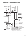
SYSTEM CONFIGURATIONS
Either
GPS antenna
GPA-017S or 017
VHF
antenna
GPS/VHF
combined antenna
GVA-100-T
Distributor
DB-1
PC
HUB
AIS TRANSPONDER
FA-50
EXTERNAL
DISPLAY
EXTERNAL
DISPLAY
CONTACT SWITCH*2
(Silent switch)
NAVNET
NAVNET
RADAR
CHART PLOTTER
ECDIS
PILOT PLUG
OR
SENSOR
AC-DC POWER
SUPPLY PR-240
GPS*1 (ex. GP-150)
SPEED LOG
GYROCOMPASS
SATELLITE COMPASS
OR
100-115/
200-230VAC
1ø, 50/60 Hz
24 VDC
: Standard supply
: Optional supply
: Local supply
12-24 VDC
IF-1500AIS
FR-8xx2 SERIES
*1: Usaually FA-50 uses the internal GPS. When connecting the
external GPS, use one which satisfies the following points.
1) Outputs DTM sentence (WGS-84 can be chosen.)
2) Outputs GBS sentence.
3) Outputs sentences with the mode indicator;
GNS: Ver.3.0 and later GLL: Ver.2.0 and later
GGA: Ver.2.0 and later RMC: Ver.1.5 and later
GPS navigator GP-150 meets with requirements shown above.
*2: Only for ships that are not required to carry a class B transponder.
vii
SYSTEM CONFIGURATIONS
This page is intentionally left blank.
viii
1.
INSTALLATION
1.1
Equipment List
Standard supply
Name
Type
Code No.
Qty
Remarks
AIS transponder
FA-50
-
1
Antenna unit
GVA-100
-
1
GPA-017S
-
1 set
GPS antenna
GPA-017
-
1 set
GPS antenna w/10 m
cable
Distributor
DB-1
-
1
Spare parts
SP05-05801
001-031-960
1 set
4A fuses (Type: FGMB
125V 4A, Code No.:
000-157-482-10)
Installation
materials
CP24-00502
005-955-560
1 set
For GPA-017S
CP05-11401
001-031-970
1 set
For FA-50, self-tapping
screws (Type: 4x20,
Code No.: 000-158850-10)
TNC-PS/PS3D-L15M-R
000-133-670-11
CP24-00101
CP24-00141
GPS/VHF combined
For GVA-100
1
For GPA-017S, 15 m
cable
005-950-730
1 set
For DB-1, self-tapping
screws (Type: 4x30,
Code No.: 000-162659-10)
005-952-330
1
For GVA-100T
1-1
1. INSTALLATION
Optional supply
Name
Type
Code No.
AC-DC power supply
PR-240
Whip antenna
CP05-11001
001-034-670
For outside Japan
Antenna cable set
CP20-02700
004-381-160
For GPA-017S
CP20-02710
004-381-170
For GPA-017S
CP24-00300
000-041-938
For GVA-100
CP24-00310
000-041-939
For GVA-100
Coaxial cable
TNC-PS/PS-3DL15M-R
000-133-670-11
TNC-TNC, 15 m
Right-angle antenna
base
No.13-QA330
000-803-239
For GPA-017/S
L-angle antenna base
No.13-QA310
000-803-240
For GPA-017/S
Antenna base for rail
mount
No.13-RC5160
000-806-114
For GPA-017/S
Mast mount fixture
CP20-01111
004-365-780
For GPA-017/S
LAN cable
P5E-4PTX-BL
L=2M
000-164-634-10
2m
P5E-4PTX-BL
L=10M
000-164-637-10
10 m
MJ-A6SPF0017010C
000-159-704-11
For NavNet vx2, 1 m
MJ-A6SPF0017050C
000-159-705-11
For NavNet vx2, 5 m
MJ-A6SPF0017100C
000-159-706-11
For NavNet vx2, 10 m
MJ-A6SPF0017200C
000-159-707-11
For NavNet vx2, 20 m
MJ-A6SPF0017300C
000-159-708-11
For NavNet vx2, 30 m
Cable assy
-
Note: One FA-50 can be installed on a network.
1-2
Remarks
1. INSTALLATION
1.2
AIS Transponder FA-50
Mounting considerations, mounting
The FA-50 can be mounted on a desktop, deck or on a bulkhead. When selecting a
mounting location, keep the following points in mind:
• The temperature and humidity should be moderate and stable.
• Locate the unit away from exhaust pipes and vents.
• The mounting location should be well ventilated.
• Mount the unit where shock and vibration are minimal.
• Keep the unit away from electromagnetic field-generating equipment such as motors and generators.
• A magnetic compass will be affected if the FA-50 is placed too close to it. Observe
the compass safe distances noted in the safety instructions to prevent disturbance
to the magnetic compass.
Fix the unit to the mounting location with 4x20 self-tapping screws (supplied).
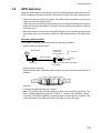
1.3
VHF Antenna
Location
The location of the AIS VHF-antenna should be carefully considered. Digital communication is more sensitive than analog/voice communication to interference created by
reflections in obstructions like masts and booms. It may be necessary to relocate the
VHF radiotelephone antenna to minimize interference effects. To minimize interference effects, the following guidelines apply:
• The AIS VHF antenna should be placed in an elevated position that is as free as
possible with a minimum of 0.5 meters in the horizontal direction from constructions
made of conductive materials. The antenna should not be installed close to any
large vertical obstruction. The objective for the AIS VHF antenna is to see the horizon freely through 360 degrees.
• There should not be more than one antenna on the same plane. The AIS VHF antenna should be mounted directly above or below the ship's primary VHF radiotelephone antenna, with no horizontal separation and with a minimum of 2.8 meters
vertical separation. If it is located on the same plane as other antennas, the distance
apart should be at least 10 meters.
• Install the VHF whip antenna (option) referring to the outline drawing at the back of
this manual. Separate this antenna from other VHF radiotelephone antennas as
shown below to prevent interference to the FA-50.
1-3
1. INSTALLATION
Whip antenna
for AIS
Other VHF
whip antenna
More than
2.8 m
More than 10 m
More than 0.5 m
Horizontal separation distance
Vertical separation distance
Cabling
• Use coaxial cable type 5D-2V or the equivalent.
• The cable should be kept as short as possible to minimize signal attenuation, and
the maximum length is 50 meters.
• All outdoor-installed connectors on coaxial cables should be fitted with preventive
isolation such as vulcanizing tape to protect against water penetration into the antenna cable.
• Coaxial cables should be installed in separate signal cable channels/tubes and at
least 10 cm away from power supply cables. Crossing of cables should be done at
right angles (90 degrees). The minimum bend radius of the coaxial cable should be
5 times the cable's outer diameter.
1-4
1. INSTALLATION
1.4
GPS Antenna
Install the GPS antenna unit referring to the outline drawing at the back of this manual.
When selecting a mounting location for the antenna, keep in mind the following points.
• Select a location out of the radar beam. The radar beam will obstruct or prevent reception of the GPS satellite signal.
• There should be no interfering object within the line-of-sight to the satellites. Objects
within line-of-sight to a satellite, for example, a mast, may block reception or prolong
acquisition time.
• Mount the antenna unit as high as possible to keep it free of interfering objects and
water spray, which can interrupt reception of GPS satellite signal if the water freezes.
Extending antenna cable
Three types of antenna cable extensions are optionally available.
• Antenna cable set CP20-02700
Conversion
Cable Assy.
NJ-TP-3DXV-1
Antenna Unit
0.6m
Antenna Cable
30m
TNCP-NJ
1m
: Connector
FA-50
Fabricate locally. (See next page.)
N-P-8DFB
Waterproofing connector
Wrap connector with vulcanizing tape and then vinyl tape. Bind the tape end with a
cable-tie.
• Antenna cable set CP20-02710 (8D-FB-CV, 50 m)
• Connect the cable the same as 1) above.
Note: The length of this cable should be less than 20 m to prevent signal loss. The
coax. coupling cable assy.(type: NJ-TP-3DXV-1, code no. 000-123-809), coaxial
connector (N-P-8DFB; supplied), vulcanizing tape and vinyl tape are required. Fabricate both ends of the cable as shown in the figure on the next page.
1-5
1. INSTALLATION
How to attach the connector N-P-8DFB for cable 8D-FB-CV
Outer Sheath
Inner Sheath
Shield
Armor
Remove outer sheath and armor by the dimensions
shown left.
Expose inner sheath and shield by the dimensions
shown left.
30
50
Cover with heat-shrink tubing and heat.
Cut off insulator and core by 10mm from its end.
10
30
Twist shield end.
Washer 1
Clamp
Nut
Slip on clamp nut, washer 1, gasket and clamp as
shown left. If it is difficult to slip the clamp onto the
cable, use a file to enlarge the inner diameter of the
clamp.
Clamp
Gasket
(reddish
brown)
Aluminum Foil
Fold back shield over clamp and trim.
Trim shield here.
Cut aluminum foil at four places, 90° from one
another.
Insulator
Fold back aluminum foil onto shield and trim.
Trim aluminum
tape foil here.
Washer 2
Slit the washer 2, and trim insulator at the end of the
washer 2.
Expose the core by 5mm.
5
Spacer (white)
Clamp Nut
Pin
Solder through
the hole.
1-6
Shell
Slip the pin onto the conductor. Solder them together
through the hole on the pin.
Insert the pin into the spacer (white) and shell.
Screw the clamp nut into the shell.
(Tighten by turning the clamp nut. Do not tighten by
turning the shell.)
1. INSTALLATION
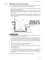
1.5
GPS/VHF Combined Antenna
Install the combined antenna unit referring to the outline drawing. When selecting a
mounting location for the antenna, keep in mind the following points.
• Select a location out of the radar beam. The radar beam will obstruct or prevent reception of the GPS satellite signal.
• There should be no interfering object within the line-of-sight to the satellites. Objects
within line-of-sight to a satellite, for example, a mast, may block reception or prolong
acquisition time.
• Mount the antenna unit as high as possible. Mounting it this way keeps it free of interfering objects and water spray, which can interrupt reception of GPS satellite signal if the water freezes.
Outdoor
Indoor
Distributor DB-1
GPS
AIS Transponder
FA-50
VHF
N-P-8DFB
RG-10U/Y or 8D-FB-CV
N-P-8DFB
Installation overview of GPS/VHF combined antenna
Mounting procedure
1. Dismount the bottom cover, cut the cable-tie inside the unit and take out the coaxial connector attached to the combined box.
2. Loosen four screws to loosen whip antenna fixture and pull out the coaxial connector coming from the combined box through the hole in the whip antenna fixture.
3. Connect the coaxial connector to the whip antenna base and wrap the junction
part of the whip antenna with vulcanizing tape and then vinyl tape for waterproofing.
4. Insert the whip antenna from the top of the combined antenna.
5. Secure the whip antenna with whip antenna fixture.
6. Using a new plastic band (supplied), secure the cables and coaxial connector inside the antenna case.
7. Mount the bottom cover.
8. Fix the GPS/VHF combined antenna to the ship's stanchion (40 to 50 mm diameter) with antenna fixing brackets, flat washers and hex. nuts. For 60 to 80 mm diameter stanchion, the mast fixing kit (Type: OP24-5, Code No.: 005-954-510) is
necessary.
Note: Coat the exposed parts of bolts and nuts with silicon sealant.
1-7
1. INSTALLATION
Whip antenna fixture
Loosen four screws.
(M5x16)
Antenna fixing bracket
Combined box
Bottom cover
GPS/VHF combined antenna
The top of the stanchion comes
into contact with the flange.
Stanchion
Installing distributor DB-1
The length of the cable between the distributor and transponder is 1 m so locate the
distributor within 1 m from the transponder. Fix the distributor on the bulkhead, facing
the cable entrance downward. Remove the lid of the distributor and secure the distributor with two self-tapping screws.
1-8
1. INSTALLATION
Self-tapping screw
(4x30)
Note: Be sure no foreign material or water enters the distributor.
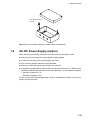
1.6
AC-DC Power Supply (option)
When selecting a mounting location for the unit, keep the following in mind:
z Keep the unit out away from areas subject to water splash.
z Locate the unit away from exhaust pipes and vents.
z The mounting location should be well ventilated.
z Mount the unit where shock and vibration are minimal.
z A magnetic compass will be affected if the unit is placed too close to it. Observe the
following compass safe distances to prevent disturbance to the magnetic compass:
• Steering compass: 0.6 m
• Standard compass: 0.9 m
Fix the unit with four self-tapping screws (4x16) to a desktop or the deck. It is not necessary to open the cover.
1-9
1. INSTALLATION
1.7
Wiring
Connect power source, LAN cable, VHF antenna and ground wires as shown below.
GPS Antenna
GPA-017/S
150M-W2VN
or FAB-151D
GPS/VHF Combined
Antenna GVA-100-T
Either
one
Distributor
DB-1
0.6 m
0.8 m
RG-10U/Y (8D-FB-CV,
option)
Attached to Distributor
(approx. 1m)
RG-10U/Y, 50 m
: Ground is not required.
8D-FB-CV, 30 m/50 m: Option
RG-10U/Y, 20 m: Local supply
AIS TRANSPONDER
LAN CABLE
P5E-4PTX-BL
PC, HUB, (2 m or 10 m)
NAVNET
POWER CABLE
(supplied)
RS-422 RATING*2
CONTACT SWITCH*3
(Silent switch)
RED
GROUND WIRE
IV-1.25sq
12-24 VDC*1
+
-
BLACK
Switchboard breaker
GROUND
: Standard
: Option
: Local Supply
*1: Supply from breaker on switchboard.
*2: If COM lines (connection for NavNet, sensor) are not used,
tape them to prevent short circuit.
*3: If CONTACT SWITCH line is not used, tape them to prevent short circuit.
1-10
1. INSTALLATION
Connection with the PC and NavNet vx2/3D
The FA-50 may be connected to a PC, or to both PC and NavNet vx2/3D. See the figure below for connection examples.
Data sentences
VDM, VDO
PC
FA-50
DIRECT CONNECTION
LAN
Data sentences
VDM, VDO,
L/L, SOG, COG, HDT
FA-50
NavNet
vx2*/3D
PC
NavNet vx2/3D CONNECTION
LAN
FA-50
Data sentences
VDM, VDO, L/L,
SOG, COG, HDT
NavNet
vx2*/3D
PC
NavNet vx2/3D CONNECTION
*Required updating software.
1-11
1. INSTALLATION
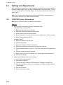
1.8
Setting and Adjustments
After installing the equipment, set up the COM port, Network and own ship's static information (MMSI, ship's name, call sign, antenna position and type of ship). The FA50 is set up from the PC or external display. The procedure below shows how to set
up from a PC.
Note: Click Tools>Internet Options>Connections>LAN settings, and uncheck the
“Use a proxy server for your LAN” before the setting.
1.8.1
COM PORT setup, Network sep
Note: Only one FA-50 may be connected to the network.
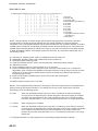
Start up
1. Start up the PC and enter IP address and subnet mask.
(Windows® 2000 Windows®XP)
1) Right-click My Network and left-click.
2) Right-click Local Area Network and left-click.
3) Select Internet Protocol and Properties.
4) Enter IP address 172.31.24.xxx (xxx=any three digits from 1 to 254, except 3).
5) Enter subnet mask 255.255.0.0.
(Windows Vista®)
1) Right-click Network and left-click.
2) Left-click Properties.
3) Right-click Manage network connections.
4) Right-click Local Area Connection, and left-click Properties.
5) Choose Internet Protocol Version 4 (TCP/IPv4), and left-click Properties button.
6) Choose Use the following IP address.
7) Enter “172.31.24.xxx” in IP address. “xxx” should be 0 to 254 other than 3.
8) Left-click OK button.
2. Open Internet Explorer and do the following:
1) Click Tools on the menu bar.
2) Click Internet Options.
3) The General tab is selected. Click Settings at Temporary Internet Files.
4) Click the radio button "Every visit to the page" at "Check for newer versions
of stored page".
5) Click the OK button.
6) Click the OK button again.
1-12
1. INSTALLATION
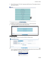
3. Enter URL as http://172.31.24.3 and press the Enter key. This number is the default value of FA-50.
*1
*2
*1: Available when Ship Type is set for “8 Tanker(s)”.
*2: Available only for ships that are not required to carry a class B transponder.
4. Click Initial Setup to show the Initial Setup screen.
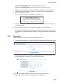
COM PORT setup
1. Click COM Port Setup to show the COM Port Setup screen.
(default=IEC61162)
2. The default setting for Data Type is IEC61162, which is suitable for most installations. If change is necessary, click the Data Type drop-down list and choose data
type as applicable, among the following choices.
1-13
1. INSTALLATION
IEC61162: Transmit and receive IEC61162 format data via COM port. (P-sentences are received but not transmitted. P-sentence is FURUNO’s original sentence.)
IEC61162+P-sentence: Transmit and receive IEC61162+P sentences format
data via COM port.
Off: FA-50 transmits no data from COM port.
With the radio buttons at RX Speed, choose how RX speed is regulated, Auto or
Manual. For manual, choose speed from the drop-down list.
Note: Tx speed is fixed at 38400 bps.
3. Click OK to confirm setting.
NETWORK setup
If connected to a LAN (via NETWORK port), set the IP address for FA-50 as shown
below.
1. Click Network Setup to show the Network Setup screen.
2. Enter the IP address assigned to the FA-50.
3. Enter subnet mask for the network.
4. Enter gateway address.
5. For NavNet connection, enter NavNet port number at NavNet Port Number. Enter
ten-thousandths and one-thousandths places.
6. At Host Name, select host name to be used in NavNet, AIS0 - AIS9, from the window.
7. At Host Name, enter host name to be used in NavNet, AIS0 - AIS9.
Auto: Auto-detect of where to output AIS data.
Continuous AIS: Output AIS data continuously.
Continuous GPS: Output GPS data (L/L, SOG, COG) continuously.
Continuous ZDA: Output time data continuously.
Continuous AIS/GPS: Output AIS/GPS data continuously.
Continuous AIS/ZDA: Output AIS/time data continuously.
1-14
1. INSTALLATION
Continuous GPS/ZDA: Output GPS/time data continuously.
Continuous AIS/GPS/ZDA: Output AIS/GPS/time data continuously.
Note: It is not necessary to change the settings of NavNet Port Number, Host
Name and AIS Data Output. Connection is available without adjusting them.
8. Click the OK button to finish.
If you changed a setting, the message below appears.
You must restart your FA-50
before the new settings will take effect.
Do you want to restart your FA-50 now?
(It will take about 1 minute to restart your FA-50)
9. Click the Yes button to restart. ER LED on the FA-50 lights. After the LED goes
off access is given.
10. The message "Please close the window." appears. Close the browser.
After restart is completed, it is necessary to access the FA-50 using new values.
For example, if you changed the IP address, use the new address to access the
FA-50.
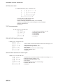
1.8.2
Ship static
Set the static data as below to use the transponder function.
1. On the Initial Setup menu, click Ship Static Edit to show the Ship Static Edit menu.
2. Enter the Login Name and Password. The Ship Static Edit screen appears. Note
that the password is known by only the FURUNO dealer.
000005044
0
0
0
0
0
0
0
0
3 Vessel
3. Enter ship's MMSI (Maritime Mobile Service Identity) in nine digits.
4. Enter ship's name, using up to 20 alphanumeric characters.
1-15
1. INSTALLATION
5. Enter call sign, using seven alphanumeric characters.
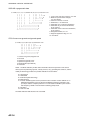
6. Set Internal/External antenna positions as follows:
1) Enter distance for location “A” of FA-50 GPS antenna.
A: Distance from bow to GPS antenna position, setting range: 0-511 m
2) Enter distance for location B, C and D similar to how you did for “A” above.
B: Distance from stern to GPS antenna position, setting range: 0-511 m
C: Distance from port to GPS antenna position, setting range: 0-63 m
D: Distance from starboard to GPS antenna position, setting range: 0-63 m
A
GPS antenna
B
C D
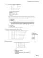
3) Enter distance for location of an external GPS antenna (if connected) similar
to how you did for the internal GPS antenna.
7. Click the down-allow button for Ship Type to show the operation window, and then
choose a ship type. (WIG: Wing in ground, HSC: High speed craft)
10 to 19: Reserved for regional use
1, 20 to 25: Reserved for future use
8. After finishing all settings, click the OK button.
1-16
2.
OPERATION
2.1
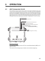
AIS Transponder FA-50
The FA-50 has no power switch. Power is fed from the ship's switchboard, and a power switch on the switchboard turns the FA-50 on or off. When powered, the PWR LED
(green) on the cover lights. The three other LEDs on the cover blink or light with equipment state. The ER LED (red) lights while the equipment is being initialized, and blinks
when equipment error is found. The RX LED (orange) lights when receiving.The TX
LED lights in blue when transmitting, and blinks in orange when TX time out occurs.
PWR (Power) LED
Lights (in green) when power is on.
ER (Error) LED
Blinks (in red) for RAM, ROM, TX/RX circuit error.
TX LED
-Lights (in blue) during transmitting.
-Blinks (in orange) when continuous transmission is
not possible (Tx time out.)
-Lights (in orange) -when not registered MMSI.
-when Silent is set to "RX Only."
TX RX
RX LED
Lights (in orange) when receiving.
Receiving messages
You may receive messages via the VHF link to a specified destination (MMSI) or all
ships in the area.
The contents of the message may be viewed on the received message log.
2-1
2. OPERATION
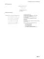
2.2
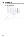
RX Message Log
You can confirm the received messages on the RX Message Log screen. Click RX
Message Log on the main menu.
Click Detail to show the full message.
Message category:
• Message 8: Received routine messages
• Message 12: Received safety messages from specific party
• Message 14: Received safety messages
To change the page, click <<Page (x/x). Flag field shows Read or “Not Read” for each
message received.
2-2
2. OPERATION
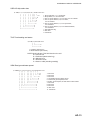
2.3
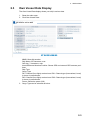
Own Vessel Data Display
The Own Vessel Data display shows your ship’s various data.
1. Show the main menu.
2. Click Own Vessel Data.
FA-50/Own Vessel Data
MMSI: Nine-digit number
Ship Name: 20 characters, max
Call sign: 7 characters, max.
Internal/External Antenna Position: Shows GPS and external GPS antenna positions.
Ship Type
Cargo Type
RX1: Channel (four digits) received over RX1. Channel type (International, Local)
is shown in parentheses.
RX2: Channel (four digits) received over RX2. Channel type (International, Local)
is shown in parentheses.
Power: Shows the power (2W)
3. Cargo Type can be selected as below.
2-3
2. OPERATION
4. Choose a type, and then click the OK button.
5. Click the Cargo Type Edit button to show the Cargo Type screen.
6. Select a Cargo Type from the drop down list and click OK.
7. Click Region List button to show the local sea area.Clicking the Detail button
shows the detailed information of the region.
8. Click <<Region List, <<Own Vessel Data in order to return to Own Vessel Data
window.
2-4
2. OPERATION
9. Click the Group Assignment button to show the Group Assignment window. This
window shows the following list when receiving a group assignment message via
VHF, own ship is cruising in the area specified on the message.
Assigned mode: Own ship's data is sent automatically with the designated interval
in the specified area.
Quite mode: Transmission is not available in the specified area.
10. Click <<Own Vessel Data, <<Top Menu to go back to the top menu.
2-5
2. OPERATION
2.4
Alarm Status
The alarm status log shows alarms violated. Click “Alarm Status” on the top menu to
show the alarm status log.
Alarm Status Indication
2-6
Meaning
TX
TX malfunction (and Error LED lights.)
RX1
TDMA RX1 Board trouble. TX stopped on corresponding
TX channel.
RX2
TDMA RX2 Board trouble. TX stopped on corresponding
TX channel.
COG
Invalid COG data.
EPFS
No data from external navigator. Continued operation possible.
HDG
Invalid/nonexistent HDG data
L/L
No L/L data
SOG
Invalid SOG data
2. OPERATION
2.5
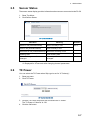
Sensor Status
The sensor status display provides information about sensors connected to the FA-50.
1. Show Top Menu.
2. Click Sensor Status.
50
Internal GPS in use
Heading valid
Channel Management Parameters Changed
Indication
Meaning
DGPS in use (Internal/External)
DGPS currently in use
GPS in use (Internal/External)
GPS currently in use
SOG/COG in use (Internal/External)
SOG/COG currently in use
Heading valid
Valid heading data
Channel Management Parameters
Changed
Channel parameters have been
changed.
Remarks
See *1.
.
See *2.
*1: Whichever navigator is in use.
*2: Displayed for 30 seconds after changing channel parameters.
2.6
TX Power
You can select the TX Power when Ship type is set for “8 Tanker(s)“.
1. Show top menu.
2. Click TX Power.
3. Click the TX Power drop-down list and select the TX Power.
The TX Power of “Normal“ is 2 W.
4. Click the OK button.
2-7
2. OPERATION
2.7
Silent
You can set your AIS transponder for receiving function only with the external silent
switch (local supply, see section 1.7). To confirm the current setting, do the following:
1. Show top menu.
2. Click Silent to show the Silent screen.
3. Confirm that the current setting, “Normal (both of TX and RX)” or “RX Only”.
Silent screen (Normal)
Silent screen (RX Only)
Note: This mode is available only for ships that are not required to carry a class B transponder.
2-8
3.
MAINTENANCE,
TROUBLESHOOTING
WARNING
3.1
NOTICE
Do not open the shield
cover unless totally familiar
with electrical circuits and
service manual.
Do not apply paint, anti-corrosive sealant
or contact spray to coating or plastic
parts of the equipment.
Only qualified personnel
should work inside the
equipment.
Those items contain organic solvents that
can damage coating and plastic parts,
especially plastic connectors.
Maintenance
Regular maintenance helps good performance. Check the items listed below monthly
to keep your equipment in good working order.
Item
Check point, remedy
Wiring
Check that each cable and wire are securely fastened.
Refasten if necessary.
Ground
Check grounding for rust. Clean if necessary.
Antenna
Check antenna and its cabling for damage.
Replace if necessary.
Cabinet
Dust and dirt should be removed from the cabinet with a soft, dry
cloth. Do not use chemical-based cleaners; they can remove paint
and markings.
3-1
3. MAINTENANCE, TROUBLESHOOTING
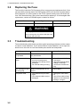
3.2
Replacing the Fuse
The fuse (4A) inside the FA-50 protects it from overcurrent and equipment fault. If the
unit cannot be powered, that is, the PWR (power) LED is off, the fuse may have blown.
If this happens, turn off the power to the FA-50, open the body cover and check the
fuse. If the fuse has blown, find out the reason before replacing it. If it blows again after
replacement, contact a FURUNO agent or dealer for advice.
Part
Type
Fuse (4A)
Code No.
FGMB 125V 4A PBF
000-157-482-10
WARNING
Use the proper fuse.
Use of a wrong fuse can result in damage to the
equipment and cause fire.
3.3
Troubleshooting
The troubleshooting table below provides typical operating problems and the means
to restore normal operation. If you cannot restore normal operation, do not open the
shield cover; there are no user serviceable parts inside the transponder.
Symptom
3-2
Problem
Remedy
Transponder cannot
be powered.
Fuse inside the transponder
may have blown.
Replace the fuse.
Cannot transmit/receive
• VHF antenna cable connection may haveloosened.
• Antenna or its cabling may be
damaged.
• Rx channel setting is wrong.
• Check if the cable is firmly
connected.
• Check the antenna and its
cabling for damage.
• Confirm the channel setting.
The message is sent
to wrong ship.
Setting of transmission is not
correct.
Confirm MMSI.
No position data
• GPS antenna may be damaged.
• GPS antenna cable may be
damaged.
• Change the GPS antenna.
• Check if the cable is firmly
fastened. If the cable has
damage, change it.
3. MAINTENANCE, TROUBLESHOOTING
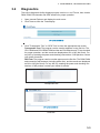
3.4
Diagnostics
The built-in diagnostic facility displays program version no. and TX text, then checks
RAM, ROM, RX channels and GPS antenna for proper operation.
1. Open Internet Explorer and display the main menu.
2. Click Tests to show the Tests display.
3. Click "Transponder Test" or "GPS Test" to show the appropriate test screen.
Transponder Test: The program version number appears on the first line. The
CPU1 RAM and CPU2 RAM, ROM and the two RX channels and TX are checked
for proper operation, and the results are displayed as OK or NG (No Good). For
any NG, try resetting the power and checking connections. If NG persists, contact
your dealer for advice.
GPS Test: The program version number appears on the first line. The ROM, RAM
and connection with antenna (including power line), and the results are displayed
as OK or NG (No Good). For any NG, try resetting the power and checking connections. If NG persists, contact your dealer for advice.
Transponder test
OK
GPS test
3-3
3. MAINTENANCE, TROUBLESHOOTING
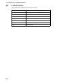
3.5
List of Terms
The following table shows the terms used in FA-50.
Terms
3-4
Meaning
COM
Communication
TX
Transmit
RX
Receive
MMSI
Maritime Mobile Service Identity
AIS
Automatic Identification System
GPS
Global Positioning System
ZDA
Time and date
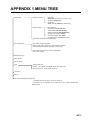
APPENDIX 1 MENU TREE
Initial Setup
COM Port Setup
Data Type
(IEC61162, IEC61162+P-sentence, Off)
TX Speed (38400 bps)
RX Speed
(Auto, Manual (4800 bps, 38400 bps))
Network Setup
MAC Address
IP Address (172.031.024.003)
Subnet Mask (255.255.000.000)
Gateway Address (000.000.000.000)
NavNet Port Number (10000)
Host Name (AIS0-AIS9, AIS0)
AIS Data Output (Continuous, Auto)
Ship Static Edit (Required a password.)
Own Vessel Data
Own Static (Cargo Type Edit)
(MMSI, Ship Name, Call Sign, Internal Antenna Position,
External Antenna Position, Ship Type, Cargo Type)
View Channel (Region List, Group Assignment)
(RX1, RX2, Power)
RX Message Log
Alarm Status
Sensor Status
Tests
Transponder Test
(Version, CPU1RAM, CPU2RAM, ROM, RX1, RX2, TX)
GPS Test (Version, ROM, RAM, Antenna)
TX power*1
Silent*2
For Service (Required a password.)
*1: Available when Ship Type is set for “8 Tanker(s)”.
*2: Available only for ships that are not required to carry a class B transponder.
bold: default
AP-1
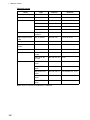
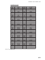
APPENDIX 2 VHF CHANNEL LISTS
USA mode
Ch No.
1001
1003
1005
6
1007
1018
1019
1020
1021
1022
1023
1024
1025
1026
1027
1028
1061
1063
1064
1065
1066
67
68
69
70
71
72
73
74
75
76
77
1078
1079
1080
1081
1082
1083
1084
AP-2
Frequency (MHz)
156.05
156.15
156.25
156.3
156.35
156.9
156.95
157
157.05
157.1
157.15
157.2
157.25
157.3
157.35
157.4
156.07
156.175
156.225
156.275
156.325
156.375
156.425
156.475
156.525
156.575
156.625
156.675
156.725
156.775
156.825
156.875
156.925
156.975
157.025
157.075
157.125
157.175
157.225
Ch No.
1088
2001
2002
2003
2004
2005
2007
8
9
10
11
12
13
14
15
16
17
2018
2019
2020
2021
2022
2023
2024
2025
2026
2027
2028
2060
2061
2062
2063
2064
2065
2066
2078
2079
2080
2081
2082
2083
2084
2085
Frequency (MHz)
157.425
160.65
160.7
160.75
160.8
160.85
160.95
156.4
156.45
156.5
156.6
156.6
156.65
156.7
156.75
156.8
156.85
161.5
161.55
161.6
161.65
161.7
161.75
161.8
161.85
161.9
161.95
162
160.625
160.675
160.725
160.775
160.825
160.875
160.925
161.525
161.575
161.625
161.675
161.725
161.775
161.825
161.875
APPENDIX 2 VHF CHANNEL LISTS
International mode
Ch No.
1001
1002
1003
1004
1005
6
1007
1018
1019
1020
1021
1022
1023
1024
1025
1026
1027
1028
1060
1061
1062
1063
1064
1065
1066
67
68
69
70
71
72
73
74
75
76
77
1078
1079
1080
1081
1082
1083
1084
1085
1086
1087
Frequency (MHz)
156.05
156.1
156.15
156.2
156.25
156.3
156.35
156.9
156.95
157
157.05
157.1
157.15
157.2
157.25
157.3
157.35
157.4
156.025
156.075
156.125
156.175
156.225
156.275
156.325
156.375
156.425
156.475
156.525
156.575
156.625
156.675
156.725
156.775
156.825
156.875
156.925
156.975
157.025
157.075
157.125
157.175
157.225
157.275
157.325
157.375
Ch No.
1088
2001
2002
2003
2004
2005
2007
8
9
10
11
12
13
14
15
16
17
2018
2019
2020
2021
2022
2023
2024
2025
2026
2027
2028
2060
2061
2062
2063
2064
2065
2066
2078
2079
2080
2081
2082
2083
2084
2085
2086
2087
2088
Frequency (MHz)
157.425
160.65
160.7
160.75
160.8
160.85
160.95
156.4
156.45
156.5
156.55
156.6
156.65
156.7
156.75
156.8
156.85
161.5
161.55
161.6
161.65
161.7
161.75
161.8
161.85
161.9
161.95
162
160.625
160.675
160.675
160.775
160.825
160.875
160.925
161.525
161.575
161.625
161.675
161.725
161.775
161.825
161.875
161.925
161.975
162.025
CH13, 67: operate on 1W.
AP-3
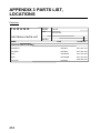
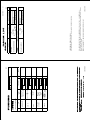
APPENDIX 3 PARTS LIST,
LOCATIONS
Parts lists
FURUNO
Model
Unit
FA-50
Tranponder
ELECTRICAL PARTS LIST
Blk.No.
NAME
TYPE
CODE NO.
PRINTED CIRCUIT BOARD
MAIN&TX
05P0814
001-034-470
POWER
05P0809
001-034-460
RX1
05P0808A
001-015-620
RX2
05P0808B
001-015-630
GPS TB
24P0043
005-955-290
AP-4
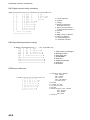
APPENDIX 3 PARTS LIST, LOCATIONS
Parts location
Transponder
MAIN&TX Board
05P0814
RX1 Board
05P0808A
RX2 Board
05P0808B
GPS TB
24P0043
POWER Board
05P0809
AP-5
APPENDIX 4 DIGITAL INTERFACE
Sentence data
Input sentences
ACK, AIQ, BBM, DSC, DSE, DTM, GBS, GGA, GLL, GNS, HDT, OSD, RMC, SSD, THS, VBW,
VSD, VTG
Output sentences
ABK, ACA, ACS, ALR, TXT, VDM, VDO
Transmission intervalABK: With each event
ACA, ACS: At RX/Switch information the region
ALR: 25 s during alarm, 2 min normally no alarm
TXT: Status is changed.VDM: At RX VHFVDO: 1 s
Load requirements as listener
Isolation: opto coupler
Input Impedance: 470 ohms
Max. Voltage: ±15 V
Threshold: 3 mA (In case of FURUNO device talker connection)
Output drive capability
Differential driver outputR=54 ohm, 1.1 V minR=60 ohm, 1.1 V minDriver short-circuit current: 250
mA max.Data transmissionData format and protocol are transmitted in serial asynchronous form
in accordance with the stan-dard referenced in 2.1 of IEC 61162-1. The first bit is a start bit and
is followed by data bits, least-significant-bit as illustrated below.
The following parameters are used:
Baud rate: 38.4 Kbps
Data bits: 8 (D7=0), parity none
Stop bits: 1
D0
Start
bit
AP-6
D1
D2
D3
D4
Data bits
D5
D6
D7
Stop
bit
APPENDIX 4 DIGITAL INTERFACE
Serial interface I/O circuit
Input/Output Buffer
SN65LBC179DR
COM_TD_B
COM_TD_A
RS422_TD
110Ω
RS422_RD
COM_RD_B
COM_RD_A
PC400
2.2kΩ
470Ω
GND
NMEA_RD
Sentence description
Input sentences
AIQ-AOIS query
$--AIQ,ccc,*hh<CR><LF>
|
|
|
|
| +------------------------------ 2
+------------------------------------- 1
1. Query data
2. Checksum
BBM-AIS broadcast binary message
!--BBM,x,x,x,x,x.x,s--s,x*hh<CR><LF>
|| | | |
| | |
|| | | |
| | +--- 8
|| | | |
| +------ 7
| | | | | +--------- 6
| | | | +------------- 5
| | | +---------------- 4
| | +------------------ 3
| +-------------------- 2
+---------------------- 1
1. Total number of sentences needed to transfer the message, 1 to 9
2. Message sentence number, 1 to 9
3. Sequential Message identifier, 0 to 9
4. AIS channel for broadcast of the radio message
5. VDL message number(8 or 14), see ITU-R M.1371
6. Binary data
7. Number of fill-bits, 0 to 5
8. Checksum
AP-7
APPENDIX 4 DIGITAL INTERFACE
DSC-Digital selective calling information
-DSC,xx,xxxxxxxxx,xx,xx,xx,x.x,xxxxxxxxxx,xx,a,a*hh<CR><LF>
|
|
| | | | |
|
| | |
|
|
| | | | |
|
| | +------- 11
|
|
| | | | |
|
| +------- 10
|
|
| | | | |
|
+------- 9
|
|
| | | | | +------- 8
|
|
| | | | +--------- 7
|
|
| | | +----------- 6
|
|
| | +-------------- 5
|
|
| +----------------- 4
|
|
+-------------------- 3
|
+----------------------- 2
+------------------------------ 1
1. Format Specifier
2. Address
3. Categry
4. Nature of Distress or
First Telecommand
5. Type of Communication
or Second Telecommand
6. Position
7. Time
8. MMSI of ship in distress
9. Nature of distress
10. Acknowledgement
11. Expansion indicator
DSE-Expanded digital selective calling
$--DSE,x,x,a,xxxxxxxxxx,xx,c--c,.......,xx,c--c*hh<CR><LF>
|||
|
| | |
| | |
|||
|
| | |
| | +------- 8
|||
|
| | |
+--+----------- 7
|||
|
| | +--------------------- 6
|||
|
+--+--------------------------- 5
|||
+------------------------------------- 4
| | +-------------------------------------------- 3
| +---------------------------------------------- 2
+------------------------------------------------ 1
1. Total number of messages
2. Message number
3. Query/reply flag
4. Vessel MMSI
5. Data set '1'
6. Additional data sets
7. Data set 'n'
8. Checksum
DTM-Datum referencew
$--DTM,ccc,a,x.x,a,x.x,a,x.x,ccc*hh<CR><LF>
| | | | | | | | |
| | | | | | | | +--- 7
| | | | | | | +------ 6
| | | | | | +---------- 5
| | | | +---+------------- 4
| | +---+------------------- 3
| +------------------------- 2
+---------------------------- 1
AP-8
1. Local datum W84 - WGS84
W72 - WGS72
S85 - SGS85
P90 - PE90
999 - User defined
IHO datum code
2. Not used
3. Lat offset, min, N/S
4. Lon offset, min, E/W
5. Not used
6. Reference dattum W84 - WGS84
W72 - WGS72
S85 - SGS85
P90 - PE90
7. Checksum
APPENDIX 4 DIGITAL INTERFACE
GBS-GNSS satellite fault direction
$--GBS,hhmmss.ss,x.x,x.x,x.x,xx,x.x,x.x,x.x,h,h*hh<CR><LF>
|
|
| | |
|
| | | | |
|
|
| | |
|
| | | | +--------- 11
|
|
| | |
|
| | | +--- 10
|
|
| | |
|
| | +------ 9
|
|
| | |
|
| +---------- 8
|
|
| | |
| +-------------- 7
|
|
| | | +------------------- 6
|
|
| | +------------------------ 5
|
|
| +---------------------------- 4
|
| +-------------------------------- 3
|
+------------------------------------- 2
+------------------------------------------------ 1
1.
2.
3.
4.
5.
6.
7.
8.
9.
10.
11.
Not used
Expected error in latitude
Expected error in longitude
Not used
Not used
Not used
Not used
Not used
GNSS System ID
GNSS Signal ID
Checksum
GGA-Global positioning system (GPS) fix data
$--GGA,hhmmss.ss,llll.ll,a,yyyyy.yy,a,x,xx,x.x,x.x,M,x.x,M,x.x,xxxx*hh<CR><LF>
|
| |
| | | | | | | | | |
| |
|
| |
| | | | | | | | | |
| +-- 11
|
| |
| | | | | | | | | | +---- 10
|
| |
| | | | | | | | | +--------- 9
|
| |
| | | | | | | +---+------------ 8
|
| |
| | | | | +---+------------------ 7
|
| |
| | | | +------------------------- 6
|
| |
| | | +---------------------------- 5
|
| |
| | +------------------------------- 4
|
| |
+----+--------------------------------- 3
|
+---+--------------------------------------------- 2
+------------------------------------------------------------- 1
1. Not used
2. Latitude, N/S
3. Longitude, E/W
4. GPS quality indicator
5. Not used
6. Not used
7. Not used
8. Not used
9. Not used
10. Not used
11. Checksum
GLL-Geographic position-latitude/longitude
$--GLL,llll.ll,a,yyyyy.yy,a,hhmmss.ss,A,a*hh<CR><LF>
| |
|
|
|
| | |
| |
|
|
|
| | +------- 6
| |
|
|
|
| +--------- 5
| |
|
|
|
+----------- 4
| |
|
|
+---------------- 3
| |
+------+----------------------- 2
+--+----------------------------------- 1
1. Latitude, N/S
2. Longitude, E/W
3. Not used
4. Status: A=data valid, V=data invalid (See NOTE 1.)
5. Mode indicator (See NOTE 2.)
6. Checksum
NOTE 1: The Mode indicator field supplements the status field (field 6). The
status field shoud be set to V = invalid for all values of operating mode except
for A = Autonomous and D = Differential. The positioning system Mode indicator
and status fields should not be null fields.
NOTE 2: Positioning system Mode indicator:
A = Autonomous
D = Differential
E = Estimated (dead reckoning)
M = Manual input
S = Simulator
N = Data not valid
AP-9
APPENDIX 4 DIGITAL INTERFACE
GNS-GNSS fix data
$--GNS,hhmmss.ss,llll.ll,a,yyyyy.yy,a,c--c,xx,x.x,x.x,x.x,x.x,x.x,a*hh<CR><LF>
|
| |
|
| |
| | | | | | | |
|
| |
|
| |
| | | | | | | +--- 12
|
| |
|
| |
| | | | | | +------- 11
|
| |
|
| |
| | | | | +----------- 10
|
| |
|
| |
| | | | +---------------- 9
|
| |
|
| |
| | | +--------------------- 8
|
| |
|
| |
| | +------------------------- 7
|
| |
|
| |
| +------------------------------ 6
|
| |
|
| | +--------------------------------- 5
|
| |
|
| +--------------------------------------- 4
|
| |
+-----+------------------------------------------- 3
|
+--+--------------------------------------------------------- 2
+------------------------------------------------------------------------- 1
1. Not used
2. Latitude, N/S
3. Longitude, E/W
4. Mode indicator (See NOTE 2.)
5. Not used
6. Not used
7. Not used
8. Not used
9. Not used
10. Not used
11. Navigational Status Indicator
(See NOTE 1.)
12. Checksum
NOTE 1: Mode indicator. A variable length valid character field type with the first three characters
currently defined. The first character indicates the use of GPS satellites, the second character
indicates the use of GLONASS satellites and the third indecates the use of Galileo satellites. If another
satellite system is added to the standard, the Mode indicator will be extended to four characters. New
satellite systems should always be added on the right, so the order of characters in the Mode indicator
is: GPS, GLONASS, Galileo, other satellite systems in the future. The characters should take one of
the following values:
A = Autonomous. Satellite system used in non-differntial mode in position fix
D = Differential. Satellite system used in differential mode in position fix
E = Estimated (dead reckoning) mode
F = Float RTK. Satellite system used in real time kinematic mode with floating integers
M = Manual input mode
N = No fix. Satellite system not used in position fix, or fix not valid
P = Precise. Satellite system used in precision mode. Precision mode is defined as: no deliberate
degradation (such as selective availability) and higher resolution code (P-code) is used to compute
position fix. P is also used for satellite system used in multi-frequency, SBAS or Precise Point
Positioning (PPP) mode.
R = Real Time Kinematic. Satellite system used in RTK mode with fixed integers
S = Simulator mode
The Mode indicator should not be a null field.
NOTE 2: The navigational status indicator is according to IEC 61108 requirements on ‘Navigational (or
Failure) warnings and status indications’. This field shoule not be a NULL field and the character
should take one of the following values:
S = Safe
When the estimated positoning accuracy (95 % confidence) is within the selected
accuracy level corresponding to the actual navigation mode, and integrity is available
and within the requirements for the actual navigation mode, and a new valid position
has been calculated within 1 s for a conventional craft and 0.5 s for a high speed craft.
C = Caution
When integrity is not available
U = Unsafe
When the estimated positioning accuracy (95 % confidence) is less than the selected
accuracy level corresponding to the actual navigation mode, and/or integrity is available
but exceeds the requirements for the actual navigation mode, and/or a new valid
position has not been calculated within 1 s for a conventional craft and 0.5 s for a high
speed craft.
V = Navigational status not valid, equipment is not providing navigational status indication.
AP-10
APPENDIX 4 DIGITAL INTERFACE
HDT-Heading true
$--HDT,x.x,T*hh<CR><LF>
| | |
| | +--------- 2
+----+----------- 1
1. Heading, degrees true
2. Checksum
OSD-Own ship data
$--OSD,x.x,A,x.x,a,x.x,a,x.x,x.x,a*hh<CR><LF>
| | | | | | | | | |
| | | | | | | | | +--------- 10
| | | | | | | | +----------- 9
| | | | | | | +-------------- 8
| | | | | | +------------------ 7
| | | | | +--------------------- 6
| | | | +------------------------ 5
| | | +--------------------------- 4
| | +------------------------------ 3
| +--------------------------------- 2
+------------------------------------ 1
1. Heading, degrees true
2. Heading status: A=data valid, V=data invalid
3. Vessel course, degrees true
4. Course reference, B/M/W/R/P(see NOTE)
5. Vessel speed
6. Speed reference, B/M/W/R/P(see NOTE)
7. Not used
8. Not used
9. Speed units, K(km/h) / N(Knots) / S(statute miles/h)
10. Checksum
NOTES - Reference systems(speed/course):
B = bottom tracking log
M = manually entered
W = water referenced
R = radar tracking(of fixed target)
P = positioning system ground reference
AP-11
APPENDIX 4 DIGITAL INTERFACE
RMC-Recommended minimum specific GNSS data
$--RMC,hhmmss.ss,A,llll.ll,a,yyyyy.yy,a,x.x,x.x,xxxxxx,x.x,a,a,a*hh<CR><LF>
|
| | |
| | | |
|
| | | | |
|
| | |
| | | |
|
| | | | +--- 10
|
| | |
| | | |
|
| | | +------- 9
|
| | |
| | | |
|
| | +--------- 8
|
| | |
| | | |
+-------+-+----------- 7
|
| | |
| | | |
|
| | |
| | | +----------------------------- 6
|
| | |
| | +--------------------------------- 5
|
| | |
+---+------------------------------------ 4
|
| +---+--------------------------------------------------- 3
|
+------------------------------------------------------------ 2
+---------------------------------------------------------------------- 1
1. UTC of position fix
2. Status: A=data valid,
V=navigation receiver warning
(See NOTE 1.)
3. Latitude, N/S
4. Longitude, E/W
5. Speed over ground, knots
6. Course over ground, degrees true
7. Not used
8. Mode indicator
(See NOTE 2 and 3.)
9. Navigational Status Indicator
10. Checksum
NOTE 1: The navigational status indicator is according to IEC 61108 requirements on ‘Navigational (or
Failure) warnings and status indications’. This field should not be a NULL field and the character should
take one of the following values:
S = Safe
When the estimated positoning accuracy (95 % confidence) is within the selected
accuracy level corresponding to the actual navigation mode, and/or integrity is
available and within the requirements for the actual navigation mode, and/or a new
valid position has been calculated within 1 s for a conventional craft and 0.5 s for a
high speed craft.
C = Caution
When integrity is not available
U = Unsafe
When the estimated positioning accuracy (95 % confidence) is less than the selected
accuracy level corresponding to the actual navigation mode, and/or integrity is
available but exceeds the requirements for the actual navigation mode, and/or a new
valid position has not been calculated within 1 s for a conventional craft and 0.5 s for a
high speed craft.
V = Navigational status not valid, equipment is not providing navigational status indication.
NOTE 2: Positioning system Mode indicator;
A = Autonomous. Satellite system used in non-differential mode in position fix
D = Differential. Satellite system used in differential mode in position fix
E = Estimated (dead reckoning) mode
F = Float RTK. Satellite system used in real time kinematic mode with floating integers
M = Manual input mode
N = No fix. Satellite system not used in position fix, or fix not valid
P = Precise. Satellite system used in precision mode. Precision mode is defined as: no deliberate
degradation (such as selective availability) and higher resolution code (P-code) is used to
compute position fix. P is also used for satellite system used in multi-frequency, SBAS or
Precise Point Positioning (PPP) mode.
R = Real time kinematic. Satellite system used in RTK mode with fixed integers
S = Simulator mode
NOTE 3: The positioning system Mode indicator field supplements the positioning system status field,
the status field should not be set to V = Invalid for all values of Indicator mode except for A = Autonomous
and D = Differential. The positioning system Mode indicator and status fields should not be null fields.
AP-12
APPENDIX 4 DIGITAL INTERFACE
SSD-AIS ship static data
$--SSD,c--c,c--c,xxx,xxx,xx,xx,c, aa*hh<CR><LF>
|
| |
| | | | | |
1. Ship's Call Sign, 1 to 7 characters
|
| |
| | | | | +--9
2. Ship's Name, 1 to 20 characters
|
| |
| | | | +--- 8
3. Pos. ref. point distance, "A," from bow, 0 to 511 Meters
|
| |
| | | +----- 7
4. Pos. ref. point distance, "B," from stern,
|
| |
| | +------- 6
0 to 511 Meters
|
| |
| +---------- 5
5.
Pos.
ref. point distance, "C," from port beam,
|
| |
+-------------- 4
0 to 63 Meters
|
| +------------------ 3
6. Pos. ref. point distance, "D," from starboard beam,
|
+---------------------- 2
0 to 63 Meters
+--------------------------- 1
7. DTE indicator flag
8. Not used
9. Checksum
THS-True heading and status
$--THS,x.x,a*hh<CR><LF>
| |
| +----------- 2
+---------------- 1
1. Heading, degrees true
2. Mode indicator (See NOTE.)
NOTE: Mode indicator. This field shoud not be null.
A = Autonomous
E = Estimated (dead reckoning)
M = Manual input
S = Simulator mode
V = Data not valid (including standby)
VBW-Dual ground/water speed
$--VBW,x.x,x.x,A,x.x,x.x,A,x.x,A,x.x,A*hh<CR><LF>
| | | | | | | | | | |
| | | | | | | | | | +--- 11
| | | | | | | | | +----- 10
| | | | | | | | +-------- 9
| | | | | | | +----------- 8
| | | | | | +-------------- 7
| | | | | +----------------- 6
| | | | +-------------------- 5
| | | +------------------------ 4
| | +--------------------------- 3
| +------------------------------ 2
+---------------------------------- 1
1. Not used
2. Not used
3. Not used
4. Longitudinal ground speed, knots
5. Transverse ground speed, knots
6. Status: ground speed, A=data valid V=data invalid
7. Not used
8. Not used
9. Not used
10. Not used
11. Checksum
AP-13
APPENDIX 4 DIGITAL INTERFACE
VSD-AIS voyage static data
$--VSD,x.x,x.x,x.x,c--c,hhmmss.ss,xx,xx,x.x,x.x*hh<CR><LF>
| | |
|
|
| | | | |
| | |
|
|
| | | | +--- 10
| | |
|
|
| | | +------ 9
| | |
|
|
| | +---------- 8
| | |
|
|
| +------------- 7
| | |
|
|
+---------------- 6
| | |
|
+----------------------- 5
| | | +------------------------------ 4
| | +----------------------------------- 3
| +--------------------------------------- 2
+------------------------------------------- 1
1. Type of ship and cargo category, 0 to 255
2. Maximum present static draught,
0 to 25.5 Meters
3. Persons on-board, 0 to 8191
4. Destination, 1-20 characters
5. Estimated UTC of arrival at destination
6. Estimated day of arrival at destination,
00 to 31(UTC)
7. Estimated month of arrival at destination,
00 to 12(UTC)
8. Navigational status, 0 to 15
9. Regional application flags, 0 to 15
10. Checksum
VTG-Course over ground and ground speed
$--VTG,x.x,T,x.x,M,x.x,N,x.x,K,a*hh<CR><LF>
| | | | | | | | | |
| | | | | | | | | +------- 6
| | | | | | | | +--------- 5
| | | | | | +---+----------- 4
| | | | +--+----------------- 3
| | +--+----------------------- 2
+-+----------------------------- 1
1. Course over ground, degrees true
2. Not used
3. Speed over ground, knots
4. Speed over ground, km/h
5. Mode indicator (See NOTE.)
6. Checksum
NOTE : The Mode indicator provides status information about the operation of the source
device (such as positioning systems, velocity sensors, etc.) generating the sentence, and the
validity of data being provided. the possible indications are as follows:
A = Autonomous
D = Differential
E = Estimated (dead reckoning)
M = Manual input
P = Precise. Satellite system used in precision mode. Precision mode is defined as: no
deliberate degradation (such as selective availability) and higher resolution code
(P-code) is used to compute position fix. P is also used for satellite system used in
muti-frequency, SBAS or Precise Point Positioning (PPP) mode.
S = Simulator
N = Data not valid
The Mode indicator field should not be a null field.
AP-14
APPENDIX 4 DIGITAL INTERFACE
Output sentences
ABK-UAIS addressed and binary broadcast acknowledgement
$--ABK,xxxxxxxxx,a,x.x,x,x*hh<CR><LF>
|
| | | | |
|
| | | | +--- 6
|
| | | +----- 5
|
| | +------- 4
|
| +---------- 3
|
+------------- 2
+------------------- 1
1. MMSI of the addressed AIS unit
2. AIS channel of reception
3. Message type
4. Message sequence number
5. Type of acknowledgement
6. Checksum
ACA-AIS channel assignment message
$--ACA,x,IIII.I, a,yyyyy.y,a,IIII.I,a,yyyyy.y,a,x,xxxx,x,xxxx,x,x,x,a,x,hhmmss.s*hh<CR><LF>
15
14
13
12
11
10
9
8
7
6
5
4
3
2
1
1. Sequence number, 0 to 9
2. Region Northeast corner latitude
- N/S
3. Region Northeast corner longitude
- E/W
4. Region Southwest corner latitude
- N/S
5. Region Southwest corner longitude
- E/W
6. Transition Zone Size
7. Channel A
8. Channel A bandwidth
9. Channel B
10. Channel B bandwidth
11. Tx/Rx mode control
12. Power level control
13. Not used
14. In-use flag
15. Time of in-used change
ACS-Channel management information source
$--ACS,x,xxxxxxxxx,hhmmss.ss,xx,xx,xxxx*hh<CR><LF>
6
5
4
3
2
1
1. Sequence number, 0 to 9
2. MMSI of originator
3. UTC at receipt of regional operating settings
4. UTC day, 01- to 31
5. UTC month, 01 to 12
6. UTC year
AP-15
APPENDIX 4 DIGITAL INTERFACE
ALR-Set alarm state
$--ALR,hhmmss.ss,xxx,A,A,c--c*hh<CR><LF>
|
| | | | |
|
| | | | +------------- 6
|
| | | +----------------- 5
|
| | +-------------------- 4
|
| +---------------------- 3
|
+------------------------- 2
+--------------------------------- 1
1. Time of alarm condition change, UTC
2. Local alarm number(identifier)
3. Alarm condition(A=threshold exceeded, V=not exceeded)
4. Alarm’s acknowledge state, A=acknowledged V=unacknowledged
5. Alarm’s description text
6. Checksum
TXT-Text transmission
$--TXT,xx,xx,xx,c--c*hh<CR><LF>
| | | | | |
| | | | | +--- 5
| | | +--+----- 4
| | +---------- 3
| +------------- 2
+---------------- 1
1. Total number of message, 01 to 99
2. Message number, 01 to 99
3. Text identifier
4. Text Message
5. Checksum
VDM-AIS VHF data-link message
!--VDM,x,x,x,a,s--s,x*hh<CR><LF>
| || | | | |
| | | | | | +--- 7
1. Total number of sentences needed to transfer the message, 1 to 9
| | | | | +----- 6
2. Message sentence number, 1 to 9
| | | | +-------- 5
3. Sequential message identifier, 0 to 9
| | | +------------ 4
4. AIS channel
| | +-------------- 3
5. Encapsulated ITU-R M.1371 radio message
| +---------------- 2
6. Number of fill-bits, 0 to 5
+------------------ 1
7. Checksum
VDO-AIS VHF data-link own vessel report
!--VDO,x,x,x,a,s--s,x*hh<CR><LF>
| | || | | |
1. Total number of sentences needed to transfer the message, 1 to 9
| | | | | | +--- 7
2. Message sentence number, 1 to 9
| | | | | +----- 6
3. Sequential message identifier, 0 to 9
| | | | +-------- 5
4. AIS channel
| | | +------------ 4
5. Encapsulated ITU-R M.1371 radio message
| | +-------------- 3
6. Number of fill-bits, 0 to 5
| +---------------- 2
7. Checksum
+------------------ 1
AP-16
APPENDIX 4 DIGITAL INTERFACE
VTG-Course over ground and ground speed
$--VTG,x.x,T,x.x,M,x.x,N,x.x,K,a*hh<CR><LF>
| | | | | | | | | |
| | | | | | | | | +------- 6
| | | | | | | | +--------- 5
| | | | | | +---+----------- 4
| | | | +--+----------------- 3
| | +--+----------------------- 2
+-+----------------------------- 1
1. Course over ground, degrees true
2. Not used
3. Speed over ground, knots
4. Speed over ground, km/h
5. Mode indicator (See NOTE.)
6. Checksum
NOTE : The Mode indicator provides status information about the operation of the source
device (such as positioning systems, velocity sensors, etc.) generating the sentence, and the
validity of data being provided. the possible indications are as follows:
A = Autonomous
D = Differential
E = Estimated (dead reckoning)
M = Manual input
P = Precise. Satellite system used in precision mode. Precision mode is defined as: no
deliberate degradation (such as selective availability) and higher resolution code
(P-code) is used to compute position fix. P is also used for satellite system used in
muti-frequency, SBAS or Precise Point Positioning (PPP) mode.
S = Simulator
N = Data not valid
The Mode indicator field should not be a null field.
GGA-Global positioning system (GPS) fix data
$--GGA,hhmmss.ss,llll.ll,a,yyyyy.yy,a,x,xx,x.x,x.x,M,x.x,M,x.x,xxxx*hh<CR><LF>
|
| |
| | | | | | | | | |
| |
|
| |
| | | | | | | | | |
| +-- 11
|
| |
| | | | | | | | | | +---- 10
|
| |
| | | | | | | | | +--------- 9
|
| |
| | | | | | | +---+------------ 8
|
| |
| | | | | +---+------------------ 7
|
| |
| | | | +------------------------- 6
|
| |
| | | +---------------------------- 5
|
| |
| | +------------------------------- 4
|
| |
+----+--------------------------------- 3
|
+---+--------------------------------------------- 2
+------------------------------------------------------------- 1
1. Not used
2. Latitude, N/S
3. Longitude, E/W
4. GPS quality indicator
5. Not used
6. Not used
7. Not used
8. Not used
9. Not used
10. Not used
11. Checksum
ZDA-Time and date
$--ZDA,hhmmss.ss,xx,xx,xxxx,xx,xx*hh<CR><LF>
|
| | | | ||
|
| | | | | +--------- 7
|
| | | | +----------- 6
|
| | | +-------------- 5
|
| | +------------------ 4
|
| +---------------------- 3
|
+------------------------- 2
+--------------------------------- 1
1. UTC
2. Day, 01 to 31 (UTC)
3. Month, 01 to 12 (UTC)
4. Year (UTC)
5. Local zone hours, 00h to +-13h
6. Local zone minutes, 00 to +59 as local time
7. Checksum
AP-17
This page intentionally left blank.
FURUNO
FA-50
SPECIFICATIONS OF CLASS B AIS TRANSPONDER
FA-50
1
1.1
GENERAL
Type
Class B AIS Transponder
1.2
RX capacity
2250 report/minute, 1channel
4500 report/minute, 2channel
1.3
RX system
CSTDMA dual wave simultaneous reception
1.4
Synchronous framing
Indirect synchronize from external oscillator
1.5
Operating mode
Autonomous, Assigned, polled/interrogation response
1.6
Frequency switching
Automatic
1.7
Prevention of abnormal TX
1.8
Regulations
Auto-suspend for detecting TX more than 1 second
IMO MSC.140 (76), IEC 62287-1, ITU-R M.1371-2,
DSC ITU R M.825-3, IEC 60945 ed.4 adopted
2
2.1
TRANSMITTER
Frequency range
156.025 MHz to 162.025 MHz (F1D)
2.2
Output power
1W/2W
2.3
Channel interval
25 kHz
2.4
Frequency deviation
±3 ppm or less
2.5
Transmit speed
9600 bps ± 50 ppm
2.6
Spurious Emission
9 kHz to 1 GHz, -36 dBm or less
1 GHz to 4 GHz, -30 dBm or less
3
3.1
AIS RECEIVER
Frequency range
156.025 MHz to 162.025 MHz (DSC: 156.525 MHz)
3.2
Oscillator frequency
1st local oscillator: f + (51.136/51.236 MHz)
2nd local oscillator: 51.1/51.2 MHz
3.3
Intermediate frequency
1st: 51.136/51.236 MHz, 2nd: 36 kHz
3.4
Receiving system
Double-conversion superheterodyne
3.5
Sensitivity
-107 dBm (PER 20% or less)
3.6
Error at high input level
-7 dBm
3.7
Co-channel rejection
10 dB
3.8
Adjacent channel selectivity
3.9
Spurious response
70 dB
70 dB (50 MHz to 520 MHz)
3.10 Inter-modulation
65 dB
3.11 Sensitivity suppression
86 dB (±5 MHz, ±10 MHz)
4
4.1
DSC RECEIVER (TIMESHARING SYSTEM)
Frequency
156.525 MHz (CH70)
4.2
Sensitivity
-107 dBm or less
4.3
Error at high input level
-7 dBm
SP - 1
E4442S01D
111024
FURUNO
FA-50
4.4
Co-channel rejection
10 dB
4.5
Adjacent channel selectivity
4.6
Spurious response
70 dB
4.7
Inter-modulation
65 dB
4.8
Sensitivity suppression
84 dB
4
4.1
GPS RECEIVER
Receiving frequency
1575.42 MHz
4.2
Tracking code
C/A code
4.3
Number of channel
12 channels parallel, 12 satellites
4.4
Position fixing method
All in view, 8-state Kalman filter
4.5
Position accuracy
10 m approx., 95% of the time, (HDOP ≤ 4)
70 dB
DGPS: 5m approx., 95% of the time
4.6
Tracking velocity
900 kts
4.7
Position fixing time
Warm start: 36 s typical, Cold start: 43 s typical
4.8
Geoids
WGS84
4.9
Position update interval
1s
4.10 DGPS data correcting
5
5.1
By AIS information
INTERFACE
COM I/O
Input:
RS-422 (38.4kbps) / IEC61162-1 Ed.4 (2010-11)
ACK, BBM, DTM, GBS, GGA, GLL, GNS, HDT, OSD, RMC,
SSD, THS, VBW, VSD, VTG, AIQ, DSC, DSE, PFEC
Output:
RS-422 (38.4kbps)
ABK, ACA, ACS, ALR, VDM, VDO, TXT, PFEC
5.2
NETWORK
Ethernet 10BASE-T/100BASE-TX
Input:
ACK, BBM, DTM, GBS, GGA, GLL, GNS, HDT, OSD, RMC,
SSD, THS, VBW, VSD, VTG, AIQ, DSC, DSE, PFEC
Output:
ABK, ACA, ACS, ALR, GGA, VDM, VDO, VTG, ZDA, TXT, PFEC
5.3
Function alarm
LED indication, series data output
6
POWER SUPPLY
12-24 VDC: 2.0-1.0 A
7
7.1
ENVIRONMENTAL CONDITIONS
Ambient temperature
Antenna unit
-30°C to +70°C
Transponder
-15°C to +55°C
7.2
Relative humidity
93% or less at +40°C
7.3
Degree of protection
Antenna unit
IPX6
SP - 2
E4442S01D
111024
FURUNO
FA-50
Transponder
IP20
7.4
Vibration
IEC 60945
8
8.1
COATING COLOR
GPS antenna unit
N9.5
8.2
Transponder
N2.5
SP - 3
E4442S01D
111024
%100'%614
㩄㩒㩂㩊
0
(.#69#5*'4
㩚㩀㩨㩁ਣᐔᐳ㊄
*':076
ⷺ㩏㨹㩎ޓ㩆㨷
%#$.'ޓ6+'
㩄㩧㩗㩨㨹㩂㩇
#06'00#$4#%-'6
#06ขઃ㊄ౕ
ฬޓޓ⒓
0#/'
⇛ޓޓ࿑
176.+0'
%1&'01
02&5(#
%1&'01
/575
%1&'01
/575
%1&'01
%8*6
%1&'01
41*5
ဳฬ㧛ⷙᩰ
&'5%4+26+105
%2
6;2'
ᢙ㊂
36;
↪ㅜ㧛⠨
4'/#4-5
##: 㧲㨁㧾㨁㧺㧻ޓ㧱㧸㧱㧯㨀㧾㧵㧯ޓ㧯㧻ޓ㧚㧘㧸㨀㧰
㧔⇛࿑ߩኸᴺߪޔෳ⠨୯ߢߔ&ޓޕ+/'05+105+0&4#9+0)(144'('4'0%'10.;㧕
%/&
6916;2'5#0&%1&'5/#;$'.+56'&(14#0+6'/6*'.19'4241&7%6/#;$'5*+22'&+02.#%'1(6*'722'4241&7%6
37#.+6;+56*'5#/'
ဳᑼ㩄㨺㩎㩨⇟ภ߇㧞Ბߩ႐วޔਅᲑࠃࠅᲑߦઍࠊࠆㆊᷰᦼຠߢࠅޔ߅ߥޓޕߔ߹ߡߞ߇߆ࠄߜߤޔຠ⾰ߪᄌࠊࠅ߹ߖࠎޕ
⇟ภ
01
+056#..#6+10/#6'4+#.5
Ꮏ᧚ᢱ
%1&'01
A-1
+056#..#6+10/#6'4+#.5
70+6
176.+0'
%2
)8#6*-
&'5%4+26+10%1&'ͳ
36;
䋨⇛࿑䈱ኸᴺ䈲䇮ෳ⠨୯䈪䈜䇯㩷㩷㪛㪠㪤㪜㪥㪪㪠㪦㪥㪪㩷㪠㪥㩷㪛㪩㪘㪮㪠㪥㪞㩷㪝㪦㪩㩷㪩㪜㪝㪜㪩㪜㪥㪚㪜㩷㪦㪥㪣㪰㪅䋩
%<$
㪫㪮㪦㩷㪫㪰㪧㪜㪪㩷㪘㪥㪛㩷㪚㪦㪛㪜㪪㩷㪤㪘㪰㩷㪙㪜㩷㪣㪠㪪㪫㪜㪛㩷㪝㪦㪩㩷㪘㪥㩷㪠㪫㪜㪤㪅㩷㩷㪫㪟㪜㩷㪣㪦㪮㪜㪩㩷㪧㪩㪦㪛㪬㪚㪫㩷㪤㪘㪰㩷㪙㪜㩷㪪㪟㪠㪧㪧㪜㪛㩷㪠㪥㩷㪧㪣㪘㪚㪜㩷㪦㪝㩷㪫㪟㪜㩷㪬㪧㪧㪜㪩㩷
㪧㪩㪦㪛㪬㪚㪫㪅㩷㪨㪬㪘㪣㪠㪫㪰㩷㪠㪪㩷㪫㪟㪜㩷㪪㪘㪤㪜㪅
ဳᑼ㪆䍘䍎䍢䍼⇟ภ䈏䋲Ბ䈱႐ว䇮ਅᲑ䉋䉍Ბ䈮ઍ䉒䉎ㆊᷰᦼຠ䈪䈅䉍䇮䈬䈤䉌䈎䈏䈦䈩䈇䉁䈜䇯䇭䈭䈍䇮ຠ⾰䈲ᄌ䉒䉍䉁䈞䉖䇯
A-2
#%: 䍘㪄䍢䍼⇟ภᧃየ䈱㪲㪁㪁㪴䈲䇮ㆬᛯຠ䈱ઍ䍘䍎䍢䍼䉕䈚䉁䈜䇯
㪚㪦㪛㪜㩷㪥㪬㪤㪙㪜㪩㩷㪜㪥㪛㪠㪥㪞㩷㪮㪠㪫㪟㩷㩹㪁㪁㩹㩷㪠㪥㪛㪠㪚㪘㪫㪜㪪㩷㪫㪟㪜㩷㪚㪦㪛㪜㩷㪥㪬㪤㪙㪜㪩㩷㪦㪝㩷㪩㪜㪧㪩㪜㪪㪜㪥㪫㪘㪫㪠㪭㪜㩷㪤㪘㪫㪜㪩㪠㪘㪣㪅
+056#..#6+10/#6'4+#.5
Ꮏ᧚ᢱ
Ꮏ᧚ᢱ
)258*(%1/$+0''00#
ⶄวⓨਛ✢ㇱ
࡙࠾࠶࠻
0#/'
)8#6*-
㧼㧭㧯㧷㧵㧺㧳ޓ㧸㧵㧿㨀
8+0;.6#2'
㩕㩨㩐㨺㩣㩍㨺㩖㩩
+057.#6+106#2'
⛘✼㩍㨺㩖㩩
%1#:+#.%100'%614
#ਸ਼
㩄㩒㩂㩊
60%0
%100'%614
㩄㩒㩂㩊
0
#ਸ਼%#$.'#55'/$.;
ᄌ឵㩃㨺㩖㩨㩣⚵ຠ
ฬޓޓ⒓
0#/'
⇛ޓޓ࿑
176.+0'
%1&'01
8-
%1&'01
7㩍㨺㩖㩩ޓ::/
%1&'01
60%20,
%1&'01
02&5(#
%1&'01
0,62&:8
ဳฬ㧛ⷙᩰ
&'5%4+26+105
%2
6;2'
ᢙ㊂
36;
↪ㅜ㧛⠨
4'/#4-5
#%: 㧲㨁㧾㨁㧺㧻ޓ㧱㧸㧱㧯㨀㧾㧵㧯ޓ㧯㧻ޓ㧚㧘㧸㨀㧰
㧔⇛࿑ߩኸᴺߪޔෳ⠨୯ߢߔ&ޓޕ+/'05+105+0&4#9+0)(144'('4'0%'10.;㧕
%/(
6916;2'5#0&%1&'5/#;$'.+56'&(14#0+6'/6*'.19'4241&7%6/#;$'5*+22'&+02.#%'1(6*'722'4241&7%6
37#.+6;+56*'5#/'
ဳᑼ㩄㨺㩎㩨⇟ภ߇㧞Ბߩ႐วޔਅᲑࠃࠅᲑߦઍࠊࠆㆊᷰᦼຠߢࠅޔ߅ߥޓޕߔ߹ߡߞ߇߆ࠄߜߤޔຠ⾰ߪᄌࠊࠅ߹ߖࠎޕ
⇟ภ
01
+056#..#6+10/#6'4+#.5
Ꮏ᧚ᢱ
%1&'01
A-3
D-1
7/Feb/2014 H.MAKI
D-2
Mar,27'07 R.Esumi
D-3
Feb.22'05
Jan. 9, '03
D-4
D-5
Nov.28'03
15/May/2014 H.MAKI
D-6
C
B
A
*4
2m
P
P P
RJ45
WHT
BLU
YEL
GRN
BRN
PPL
GRY
1
2
3
4
5
6
7
8
P
P
NOTE
*1: SHIPYARD SUPPLY.
*2: OPTION.
*3: USE STRAIGHT LAN CABLE WHEN A HUB W/O AUTO MDI/MDI-X FUNCTION IS USED.
*4: IF COM LINES ARE NOT USED, TAPE THEM TO PREVENT SHORT-CIRCUIT.
17/Jul/2014
DWG.No.
SCALE
C4442-C01- G
MASS
17/Jul/2014 H.MAKI
H.MAKI
kg
GSC-001
NAME
名 称
TYPE
CLASS B AIS TRANSPONDER
INTERCONNECTION DIAGRAM
簡易型船舶自動識別装置
相互結線図
FA-50
N-P-8DFB
N-J-3
ホイップアンテナ
WHIP ANTENNA
FAB-151D(JAPAN ONLY)
150M-W2VN
*2
複合空中線部
GPS/VHF ANTENNA
GVA-100
アンテナ構成は選択とする
SELECT ANTENNA CONFIGURATION
分配器
N-J-3 N-P-8DFB 8D-FB-CV,30/50m *2
RG-10/UY,MAX.20m *1
DISTRI- 1m
BUTOR
DB-1
05-097-2002-1
TNC-P-3
1m
REF.No.
GPS
ANT
VHF M-P-3 1m
ANT
*1
N-P-8DFB
*2
TNCP-NJ
TNC-J-3
GPA-017S
GPS ANTENNA
*1
N-P-8DFB 8D-FB-CV,30/50m *2
RG-10/UY,MAX.20m *1
*2
TNC-PS/PS-3D-L15M-R,15m
10m
NJ-TP-3DXV,1m
TNC-P-3
4
ホイップアンテナ
WHIP ANTENNA
FAB-151D(JAPAN ONLY)
150M-W2VN *2
*1
FM-MP-5
GPA-017
*1
5D-2V OR
*1
J1 FM-MP-5 RG-10/UY,MAX.50m
T.YAMASAKI
GPS ANT
VHF ANT
17/Jul/2014
APPROVED
CHECKED
GND *1
IV-1.25sq.
MAIN &
TX & GPS
05P0814
DRAWN
NETWORK
J1
E_TD_P
E_TD_N
E_RD_P
NC
NC
E_RD_N
NC
NC
J17
1 DC_P(+)
2 DC_M(-)
J9
1 TD-A
2 TD-B
3 RD-H
4 RD-C
5 0V
6 SILENT-H
7 SILENT-C
COM/POWER
簡易型船舶自動識別装置
CLASS B AIS TRANSPONDER
FA-50
注 記
*1)造船所手配。
*2)オプション。
*3)Auto MDI/MDI-X対応でないHUBのときは、ストレートケーブルを使用する。
*4)COMラインを使用しないときは、芯線がショートしないようテープで絶縁する。
2
3
4
5
6
7
8
P
シロ
アオ
キ
ミドリ
チャ
ムラサキ
ハイ
アカ RED
クロ BLK
スイッチングハブ
*2 *3
SWITCHING HUB
RJ45
P5E-4PTX-BL,2/10m
TX_P 1
TX_N
*1 *3 RJ45
外部
RX_P
表示器 STP CABLE (CAT5)
NC
NC
EXTERNAL
RX_N
DISPLAY
NC
(AUTO MDI/MDI-X) NC
PC
*1 *3 RJ45
STP CABLE (CAT5)
外部表示器/センサー
EXT. DISPLAY/SENSOR
(RS-422/IEC61162-1)
FG
TD-A
IF-1500AIS TD-B
または OR
RD-A
GPS航法装置 RD-B
GPS NAVIGATOR
GP-150
AC
IN
+ DC
- IN
AC/DC電源 DC +
ユニット OUT AC/DC POWER E
SUPPLY UNIT
PR-240
*2
PE *1
IV-1.25sq.
12-24VDC (+)
(-)
JB *1
MJ-A7SPF MJ-A7SPF0003-050C,5m,φ6
1
シロ WHT
P
2
クロ BLK
3
キ
YEL
P
4
ミドリ GRN
5
P アカ RED
TTYCS-1 *1
6
アオ BLU
MAX.50m
7
SILENT SWITCH
100-115/
200-230VAC
1φ,50/60Hz
*1
DPYC-1.5
3
0.2m
2
0.8m
1
S-1
INDEX
A
AC-DC power supply................................. 1-9
alarm status............................................... 2-6
C
COM PORT............................................. 1-13
D
distributor .................................................. 1-8
F
Fuse .......................................................... 3-2
fuse ........................................................... 3-2
G
GPS antenna............................................. 1-5
GPS/VHF combined antenna.................... 1-7
I
index term ...............................................AP-6
IP address ............................................... 1-12
M
maintenance.............................................. 3-1
menu tree ................................................AP-1
N
NETWORK.............................................. 1-14
O
optional supply .......................................... 1-2
own vessel data ........................................ 2-3
P
parts lists .................................................AP-4
parts location...........................................AP-5
S
sensor status............................................. 2-7
serial interface I/O circuit.........................AP-7
standard supply......................................... 1-1
subnet mask............................................ 1-12
T
troubleshooting.......................................... 3-2
V
VHF antenna ............................................. 1-3
IN-1