1
Distributed by: minilablaser.com
F-235 Service Manual
Distributed by: minilablaser.com
Scanner Specifications
Minimum Host Computer Specifications
•
•
•
•
•
•
•
•
Pentium IV CPU 1.7GHZ or higher
1 40GB hard drive to be used for the operating system, application programs, and storage. If
IDE, it must be configured as Primary Master.
1 40GB hard drive capable of a sustained transfer rate of 30MB/sec. This is to be a dedicated
drive for the scan data buffer. If IDE, it must either be a Secondary Master drive or connected using a serial ATA connection. Drive letter must be N:\ and it must NOT be formatted. This should be a 7200rpm drive. See the “Disk Management” chapter for more
information on configuring this drive.
Windows 2000, Service Pack 2
512MB of RAM
A motherboard with an integrated USB 2.0 controller as part of the motherboard chipset. A
dedicated port is recommended. USB 2.0 hubs have not been fully tested for reliability.
Separate AGP Graphics card. Using a motherboard with a built-in graphics card will be problematic.
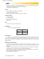
Motherboards with the following chipsets are recommended:
Recommended
Motherboards and Chipsets
Intel 845E
Intel 845GE
Intel 845G
Intel 845PE
Intel 845E
Intel 865GBFL
SIS 651
SIS 962
SIS 645DX
SIS 648
VIA VT8235 integrated USB controller
•
•
•
Microsoft USB 2.0 drivers.
Integrated video cannot be used. Use an add-on AGP video card.
SCSI CD-RW drive if both hard drives are IDE. (Plextor 12/10/32S or 40/10/40S recommended, and required for Kodak Picture CD support.) If using a serial ATA hard drive, the
Pakon Part#124794-D
June 5, 2003
1
Distributed by: minilablaser.com
•
CD-R can be an IDE drive. (Plextor CD-R PX-W48, 52/24/52A, or PlexWriter Premium recommended, and required for Kodak Picture CD support)
1.5GB Pagefile.(Virtual Memory)
Power
•
•
•
Auto-switching power supply for 100-240VAC
50-60Hz Input voltage frequency
Standard 3 conductor IEC 320 male power cable connector
Contents of Box
•
•
•
•
F-235 Film Scanner
6ft. USB 2.0 Cable
Software and User Manual CD
Power Cord
Size
•
17.3”W x 13.6”H x 12.6”D with cover on
Resolutions
There are three supported resolutions.
4Base
1000 x 1500
8Base
1400 x 2100
16Base
2000 x 3000
Light Source
The F-235 uses a 50 Watt Solux Halogen light bulb. During scans, the bulb operate at standard voltage. After completing a scan operation, the bulb power will be reduced to a lower voltage to increase the bulb’s life expectancy. Using an alternative light source will cause image
quality problems.
Film Types and Variations
•
•
•
•
The F-235 is designed to scan film in 35mm and 24mm (APS) formats. Color negative, color
reversal (positive or slide) film, black and white, C-41 processed black and white films are all
supported.
APS film can only be scanned once removed from the canister, but cannot be cut into strips.
All APS formats (C, H, and P) will scan only in full frame (H) format.
35mm cut strips are supported in sizes from 2 frames to 40 frames. However, to ensure DX
code reading, the strips must be a minimum of 3 frames.
Mounted slides are not supported.
Pakon Part#124794-D
June 5, 2003
2
Distributed by: minilablaser.com
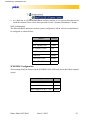
DX Code Reading
•
•
35mm DX codes are read using the ISO 1007 specifications and are used by the host manager.
APS encoding will only be read by a full roll of film, and will not be read from an APS strip.
Pakon Part#124794-D
June 5, 2003
3
Distributed by: minilablaser.com
Scanner Theory
The F-235 film scanner is a stand alone USB 2.0 device, designed as a high speed scanning solution. It is highly flexible, and can easily be integrated into a larger digital photo processing system, or operated as an independent scanning device, attached to a host computer.
Optical Tower
The scanner is designed around an optical tower, which suspends the lens and CCD
assembly above the film track. Both the lens and CCD assembly are on stepper motors that move
up and down on these stepper bars. There are four sets of stepper positions: one for 8 Base and 16
Base focus positions for 35MM and APS. Each of these positions are determined by calibration,
performed during manufacturing or by authorized service technicians. 4 Base scan resolution uses
16 Base resolution that uses CCD binning to create a lower resolution. The client interface software moves the lens and CCD assembly into the proper position after the user selects the resolution in which to scan.
Light Assembly
At the bottom of the optical tower is a small piece of glass suspended by two set screws.
This glass piece is the illuminator, or light transfer bar. The film track transports the film underneath the optical tower, but above the light transfer bar. The light transfer bar illuminates the
scanning area. The CCD chip senses the light and converts it into digital information.
The light assembly houses the Digital ICE hardware. This hardware is responsible for
removing scratches and defects in the film. When a four channel scan is initialized, this hardware
activates. The software then looks at the fourth channel (defect channel) and removes defects
from the RGB channels.
CCD Chip and Assembly
The CCD chip is trilinear--it senses three colors: red, green, and blue. Film traveling forward through the film track. A skew in the CCD assembly will cause scanned images to be
skewed. The result would turn “Skew” into “Skew.” The image would appear slanted, as the italicized “skew” demonstrates. A skew adjustment procedure is performed during the scanner’s orig-
Pakon Part#124794-D
June 5, 2003
4
Distributed by: minilablaser.com
inal manufacturing calibration process to properly align the CCD board. Epoxy is used to glue the
CCD board into the proper skew position.
The CCD board requires a tilt adjustment be done to ensure that the distance from one end
of the CCD is the same as the opposite end. If these distances are not equal, then one edge of a
scanned picture will be in focus, and the other edge of the picture will be out of focus. This procedure is performed during the scanner’s original manufacturing calibration process. Epoxy is used
to glue the CCD board into the proper tilt position.
As the film is scanned, the data is converted into raw digital data through the 14 bit A/D
chip on the CCD board. This data is transferred from the CCD board to the USB interface board
and sent to the host PC. The host computer saves this data in a buffer in a specific path (determined in the registry, see Important Registry Keys), where it is later accessed by the client.
Lens
The lens is mounted to a bracket that can swivel from side to side and forward and backward. During the manufacturing process a lens alignment fixture is used to position the lens in the
proper alignment with the film track and CCD chip. Once the proper position is determined, the
lens mount bracket is glued so the lens cannot move after the manufacturing calibration process.
Lamp Board
The lamp board, on the back side of the scanner regulates the lamp’s power and temperature. There is a temperature monitor attached to the heat sink on the lamp board that turns off the
power to the light bulb if the temperature reaches 72 degrees Celsius. It is important that the scanner is well ventilated so the scanner does not overheat and turn off the bulb.
The lamp board also connects to the LED board, for Digital ICE operation. The thin ribbon cable is used to communicate between these two boards.
Motor Control and DX Board
The motor control and DX functions of the scanner are all performed by the largest circuit
board in the scanner. It is located on the undercarriage of the frame. This board controls all
motors: lens and CCD steppers, film guides, film rollers, and the filter wheel.
The lens and CCD steppers are move the lens and CCD to predefined focus positions, as
outlined in the “Optical Tower” section above. The film guides open and close the film gate to
Pakon Part#124794-D
June 5, 2003
5
Distributed by: minilablaser.com
accommodate 35MM and APS (24MM) film. The film rollers grip the film using rubber o-rings
to transport the film through the film track.
Motor Speed
The calibration wizard sets the film speed in the final phase of the calibration procedure.
Each resolution, film type, and 3 channel and 4 channel setting must have its own film speed.
These settings, as all calibration settings are stored in the EEPROM of the scanner, on the USB
board in the scanner.
Filter Wheel
The filter wheel has three positions: negative, positive, and block. The negative position
moves the filter wheel to position a negative filter in front of the light assembly. It produces a
cyan light. The positive position moves a positive filter in front of the light assembly, producing a
white light.
Each position has a unique function. The block position blocks all light to the light assembly. It is used for setting the offset while doing force corrections. The negative filter is used for
color negative film and C-41 processed black and white film. The positive filter is used for positive film and black and white film.
APS and 35MM Film Guides
The film track is designed to default to 35MM size film. A stepper motor can contract the
film track to accommodate APS (24MM) film. The guides will open and close as the user determines the position by selecting the desired film type in the interface software.
DX Sensors
The film track has DX sensors built into the assembly. These sensors are positioned so
they have the ability to read DX code on both sides of the film. The DX codes will report film
type and film specifier values. They also determine index numbers for each frame. To see requirements for DX code reading, please refer to the “Scanner Specifications” chapter.
USB Board
The F-235 scanner communicates to a host PC via a USB 2.0 interface. The scanner has a
USB interface board built into it. This board communicates with the scanner, and then relays that
information to the host PC.
Pakon Part#124794-D
June 5, 2003
6
Distributed by: minilablaser.com
The USB board has an EEPROM chip built into it to store calibration information. The
Calibration Wizard program writes all calibration data to this EEPROM chip. When the scanner
interface software is launched, this calibration data in the EEPROM is written to the Windows
registry. This means that a F-235 scanner will be properly calibrated and functional when attached
to any PC that meets the Computer Requirements outlined in the first chapter.
Pakon Part#124794-D
June 5, 2003
7
Distributed by: minilablaser.com
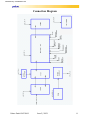
Connection Diagram
Pakon Part#124794-D
June 5, 2003
8
Distributed by: minilablaser.com
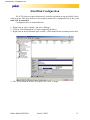
Hard Disk Configuration
The F-235 software requires that there be a hard drive partition set up specifically for the
software to use. This drive needs to be the secondary master drive, configured as the N: drive, and
must NOT be formatted.
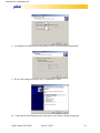
Configure the drive as instructed below:
1. Right-click on “My Computer” and select “Manage.”
2. Click on “Disk Management” to begin configuring the drives.
3. Right-click on the un-allocated space on disk 1, which should be the secondary master drive.
4. The “Create Partition Wizard” will open. Click “Next” to begin.
Pakon Part#124794-D
June 5, 2003
9
Distributed by: minilablaser.com
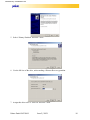
5. Select “Primary Partition” and click “Next.”
6. Use the full size of the drive, unless making a Disaster Recovery partition.
7. Assign this drive to be N:. Select N: and click “Next.”
Pakon Part#124794-D
June 5, 2003
10
Distributed by: minilablaser.com
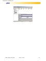
8. It is imperative to NOT format this partition. Select “Do not format this partition.”
9. Review the settings on the new drive, to finish click “Next.”
10. Verify that the Disk Management screen looks correct before closing the program.
Pakon Part#124794-D
June 5, 2003
11
Distributed by: minilablaser.com
Pakon Part#124794-D
June 5, 2003
12
Distributed by: minilablaser.com
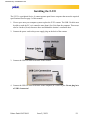
Installing the F-235
The F-235 is a peripheral device. It cannot operate apart from a computer that meets the required
specifications listed on page 2 of this manual.
1. Clear a space near your computer system to place the F-235 scanner. The USB 2.0 cable must
be able to reach the PC, so it cannot be more than 6 feet (2m) from the computer. There must
also be 4 inches (10cm) clearance above and behind the scanner’s ventilation duct.
2. Connect the power cord to the power supply plug on the back of the scanner.
3. Connect the USB 2.0 cable to the back of the scanner.
4. Connect the USB 2.0 cable to the back of the computer, in a USB 2.0 port. Do not plug in to
a USB 1.0 connector!
Pakon Part#124794-D
June 5, 2003
13
Distributed by: minilablaser.com
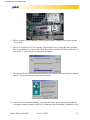
5. While computer is on and Windows 2000 is loaded, turn the scanner power switch into the
‘on’ position.
6. Insert F-235 Software CD. The computer will prompt the user to locate the driver software.
This driver software is located on the CD in \Program Files\Pakon\F235Driver. This driver is
also on the C:\ if the software has already been installed.
7. The install will ask for authorization to install the driver despite it not having been “digitally
signed.” Yes must be selected for the driver to install.
8. After the driver is finished installing, verify that the scanner driver is properly installed, by
viewing the scanner properties in the Device Manager under the heading, “Imaging Devices.”
Pakon Part#124794-D
June 5, 2003
14
Distributed by: minilablaser.com
9. As a final step, it is recommended that the installer clean the F-235 from any dust that may be
inside the scanner. Please refer to these procedures in the “Operator Maintenance” chapter.
BIOS Configuration
The following BIOS options are used on systems configured by Pakon, and are recommended to
be configured as outlined below:
Option
Setting
Plug and Play O/S
Disable
AGP Aperture Size
32MB
PCI Latency Timer
248
ACPI Suspend State
S1 State
USB Boot
Disable
PXE Boot to Lan
Disable
PCI to DRAM Prefetch
Disable
SCSI BIOS Configuration
These settings should be followed in the SCSI BIOS of the SCSI card used in the Pakon computer
system.
Option
Pakon Part#124794-D
Setting
Sync. Transfer Rates
10
Bootable CD-ROM
Disable
BIOS Support for Int. 13 Ext.
Disable
June 5, 2003
15
Distributed by: minilablaser.com
Operational Information
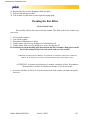
Powering On
Power on the host PC, and allow it to finish loading Windows before turning the F-235
scanner on. This will ensure that the scanner can properly communicate with the host computer.
Operation
When scanning film, ensure the appropriate film type is selected. Do not attempt to scan
35mm film when APS is selected, and likewise do not scan APS film when 35mm film has been
selected.
Insert the film emulsion side-up, with the first frame first on the right side of the
scanner. This will ensure that the DX codes are read and that the framing will be done correctly.
Do not attempt to remove film from the scanner while the scanner motor is moving! This
will cause damage to both the film and the scanner.
Calibration
There are two types of calibration for the F-235.
Color calibration is set during the manufacturing process, as well as any service that
involves the CCD or any optical filter. This is to be performed by trained and authorized service
personnel only.
Scanner corrections are performed automatically. They consist of a series of steps performed when the scanner is first turned on, as shown below:
• Start-up corrections
• Initial bulb warm-up
• Gain and exposure Control Corrections
• Run Time Corrections
Format Change
The scanner will automatically change the film guide, lens position, CCD position, or
color filter position whenever one of the following steps take place:
• Film Format change between 35mm and APS
• Film type change between color negative, color reversal, and black and white
• Magnification Change (Change of scanning resolution)
Film Gate Change
The film gate opens and closes depending on the size of the film being scanned. It will
open for 35mm film and close for APS film. This gate will open or close automatically when a
different film size is selected.
Pakon Part#124794-D
June 5, 2003
16
Distributed by: minilablaser.com
Post Warm-Up
The steppers will take less than 20 seconds to move the lens and CCD into proper position
for the selected focus position.
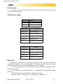
LED Indicator Lights
Power LED
Function
Solid Green
+5V is functioning
Off
+5V is not functioning
Status LED
Function
Solid Green
Scanner Ready
Blinking Green
Scanner is Scanning
Blinking Yellow
Scanner is Calibrating
Blinking Red
Scanner Error
Off
Scanner not Functioning
APS LED
Function
Solid Green
Scanner in APS mode
Blinking Green
Scanner is Scanning
Blinking Red
APS mode Error
Off
Scanner in 35MM mode
Digital ICE
Digital ICE is designed to assist in removing scratches, dust, and debris artifacts from
scanned film. It should be used as a complement to a photo lab’s normal cleaning procedures.
Customers are still advised to clean the floors and work surfaces regularly.
It is also recommended to clean all film with a lint-free cloth before attempting to make
prints 8”x10” or higher.
If a lab is having persistent dust problems, it is recommended to perform the following
regularly:
•Clean all customer film with a lint-free cloth before scanning it.
•When the scanner is turned off, cover it with a plastic, or lint-free cover.
Pakon Part#124794-D
June 5, 2003
17
Distributed by: minilablaser.com
•Use a lint-free cloth daily to clean the cover of the scanner and the surface of the table it
is positioned on.
•Clean or replace the air filter on the back of the scanner once per week.
Pakon Part#124794-D
June 5, 2003
18
Distributed by: minilablaser.com
Operator Maintenance
Warning: These procedures require the operator to remove up to two of the three covers on
the scanner. Do not attempt to operate the scanner without these covers properly in place!
WARNUNG: Bei diesen Verfahren muss der Bediener bis zu zwei der drei Abdeckungen am Scanner
entfernen. Der Scanner darf nicht betrieben werden, wenn diese Abdeckungen nicht ordnungsgemäß
angebracht sind!
ATTENTION : au cours de ces procédures, vous devez ôter deux des trois couvercles du
scanner. N'essayez pas de faire fonctionner le scanner sans que ces couvercles de
protection soient correctement à leur place !
Dust cleaning of illumination
The F-235 is a precision optical device. A relatively smoke and dust free environment is
necessary. The scanner must be cleaned periodically to remove large collections of dust or debris
inside the scanner, on the illumination. This procedure is recommended to be performed every
two weeks. Software is designed to compensate for smaller collections of dust or debris, but
cleaning may be required. Digital ICE is only designed to complement the lab’s normal cleaning
procedures--which should include cleaning the floor and work surfaces regularly.
Follow each step by a verification process to determine if the cleaning was effective. If the
verification determines that level of cleaning was ineffective, the next level is required.
1. Simple cleaning with compressed air and or lens brushes.
2. Cleaning with rubbing alcohol and a cotton swab.
3. Service call.
Cleaning the Illumination with Compressed Air
1. Turn off the scanner.
2. Disconnect the USB and power cables.
3. Gently remove the side panel of scanner, by pulling back on it. It should snap out of place.
Pakon Part#124794-D
June 5, 2003
19
Distributed by: minilablaser.com
Do not touch anything inside the scanner while the power is on. The cover is only off to
allow dust and debris to be blown out of the scanner.
WARNUNG: Berühren Sie keine Bauteile innerhalb des Scanners, während das Gerät eingeschaltet ist. Die
Abdeckung wird nur deshalb abgenommen, damit Staub und Verschmutzungen aus dem Inneren des
Scanners heraus geblasen werden können.
ATTENTION : ne touchez aucun élément interne du scanner lorsque ce dernier est sous
tension. Le couvercle est ouvert pour permettre d'éliminer poussière et débris du scanner.
4. Connect power to the scanner.
5. Turn the scanner on.
6. Remove the small film path cover.
7. Aim the hose of a can of compressed air into the film path--aiming for the clear piece of glass
in the middle.
Pakon Part#124794-D
June 5, 2003
20
Distributed by: minilablaser.com
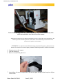
8. It may be beneficial to insert a strip of film into the scanner before blowing it out. This will
focus all the air onto the light transfer bar, and should dislodge any dust or debris.
9. When finished, put the film path cover back in place.
Turn off the scanner immediately when finished cleaning the scanner!
10. Turn off the scanner and unplug the power cable.
11. Replace the side cover by snapping into place.
12. Plug in the USB and power cables.
Cleaning Illumination with Cotton Swab
CAUTION--Be Careful not to scratch or damage the top of the glass light bar!
Turn off the scanner.
Disconnect the USB and power cables.
Gently remove the side cover.
Using a long cotton swab, dabbed in isopropyl alcohol, clean the illumination bar inside the
film track assembly.
4. The illumination bar is a small piece of glass, sitting upright.
1.
1.
2.
3.
Pakon Part#124794-D
June 5, 2003
21
Distributed by: minilablaser.com
5. After cleaning the illumation bar, replace side cover and turn on.
Light Bulb Replacement -- Click to Watch Video
The light bulb will have a nominal life of 100 working days or longer, depending on certain variables. This number is based on the following assumptions:
• 6 working days per week
• 10hours per day
Changing the light bulb does not require any special tools.
Replacing the Scanner Light Bulb
CAUTION: The lamp may be hot. Allow the bulb to cool before attempting to replace it.
Use gloves when replacing the scanner light bulb. Fingerprints can damage the light
bulb.
VORSICHT: Die Lampe kann heiß sein. Lassen Sie die Glühlampe abkühlen, bevor Sie sie austauschen.
Berühren Sie die Scanner-Glühlampe nur mit Handschuhen. Fingerabdrücke können die Glühlampe
beschädigen.
ATTENTION : l'ampoule risque d'être chaude. Attendez qu'elle refroidisse avant
d'essayer de la remplacer. Utilisez des gants pour remplacer l'ampoule du scanner. Les
empreintes digitales peuvent l'endommager.
Pakon Part#124794-D
June 5, 2003
22
Distributed by: minilablaser.com
1.
2.
3.
4.
Close all scanning software.
Turn off the scanner.
Disconnect the USB and power cables.
Gently remove the side cover by pulling on it. It should snap out of place.
5. Gently pull off the back cover. It should snap off much like the side cover.
6. Locate the small lever, just to the back of the bulb.
Pakon Part#124794-D
June 5, 2003
23
Distributed by: minilablaser.com
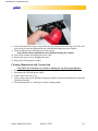
Gloves must be worn to ensure the bulb is not damaged by dirt or skin oils.
7. With one hand, gently pull the lever towards the back of the scanner.
8. As the lever is pulled, the bulb will be pushed up, and partially out of its wire harness.
9. Once the bulb has been pushed up far enough, use your other hand to gently remove the bulb
from the harness.
10. Orient the new light bulb so that the largest, or widest part of the bell shape is facing the front
of the scanner. And place the smaller end with the prongs, facing the back.
11. Rest the wide end of the bulb on the top edge of the wire harness, do not push or force it
downward.
12. Spin or rotate the bulb so that the two prongs line up with the grooves in the lamp ballast.
13. Gently apply downward pressure equally to both the front and the back of the bulb.
14. Slide the bulb into place, until it fits securely.
15. Replace the back cover by snapping it into place.
Pakon Part#124794-D
June 5, 2003
24
Distributed by: minilablaser.com
16. Replace the side cover by snapping it back into place.
17. Plug in USB and power cables.
18. Turn scanner on, and allow to warm up before using again.
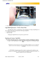
Cleaning the Fan Filter
Click to Watch Video
The fan filter collects dust from inside the scanner. This filter needs to be cleaned every
two weeks.
1. Close scanner software.
2. Turn off the scanner.
3. Disconnect USB and power cables.
4. Gently remove side cover by pulling on it. It should snap off.
5. Gently remove back cover by pulling on it. It too, should snap off.
Be Careful not to touch anything other than the fan and filter assembly. Many pieces on the
back of the scanner will be hot to the touch, and are to be avoided.
VORSICHT: Berühren Sie keine Bauteile, mit Ausnahme des Ventilators und der Filter. Zahlreiche
Bauteile an der Rückseite des Scanners sind heiß und dürfen daher nicht berührt werden.
ATTENTION : ne touchez rien d'autre que le module ventilateur et filtre. De nombreux
éléments situés à l'arrière du scanner sont chauds, évitez de les toucher.
6. Locate the Fan filter (123816). It is located on the back of the scanner, just under the plastic
fan cover.
Pakon Part#124794-D
June 5, 2003
25
Distributed by: minilablaser.com
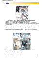
7. Pull straight back on the plastic fan cover until it comes free from the scanner housing.
8. Remove the filter from inside the cover, and rinse with tap water; replace if necessary.
Pakon Part#124794-D
June 5, 2003
26
Distributed by: minilablaser.com
9. Re-attach the fan cover by applying moderate pressure to each of the four sides, until it snaps
back in to place.
Cleaning the Film Track
It is recommended to clean the film track every two weeks, along with the illumination
cleaning. Keeping the film track clean will ensure that DX code reading remains reliable. It will
also maintain the proper motor speed for each resolution.
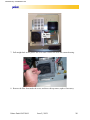
1. Remove the film path cover.
2. Position the tip of the compressed air hose on both sides of the film track entrance, and blow.
3. Position the tip of the compressed air hose on both sides of the film track exit, and blow.
4. After cleaning the film track, run the ‘Film Track Test’ in the client interface program.
5. Verify the scanner is properly reading DX codes by scanning a roll of film.
Pakon Part#124794-D
June 5, 2003
27
Distributed by: minilablaser.com
Surface Cleaning
Clean surfaces with lint-free cloths or mild, non-abrasive spray type cleaners, where the
cleaner is sprayed onto the cleaning cloth and not directly onto the equipment. Perform this type
of cleaning only with the equipment disconnected and powered down.
Pakon Part#124794-D
June 5, 2003
28
Distributed by: minilablaser.com
Field Service
Service and Repair
The scanner has the ability to determine failures at or below the FRU (Field Replaceable
Unit) level, in most cases. Only qualified service personnel are authorized to service the F-235
scanner.
Field Replaceable Units
Lamp Board Fan Assembly(124804)
Motor Control Board (123677)
Filter Wheel Assembly (124558)
Lamp Holder Assembly (124805)
Film Path Assembly (124560)
Blower Assembly (124803)
Bulb (123841)
LED Board (123691)
Magnetic Head Module (If Applicable)
Removing Covers - Click to Watch Video
Removing the F-235 covers is made easy by a locking system, that eliminates the need for all but
three screws.
1.
2.
3.
4.
Turn off power on scanner.
Disconnect all cables from scanner.
Remove film catch basket from side of scanner.
Gently pull on the side of the scanner. There are three locks that will snap out of place.
Pakon Part#124794-D
June 5, 2003
29
Distributed by: minilablaser.com
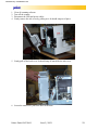
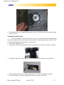
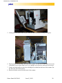
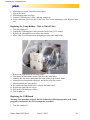
5. Gently pull of the back of the scanner. There are three locks that will snap out of place.
6. The fan on the left side of the back side of the scanner will need to be taken off to access one
of the three screws for the front cover. Use a phillips screw driver to remove the two screws
7. Gently, but firmly pull up on the fan to dislodge the sealant from the base of the scanner. Put
the fan to the side of the scanner.
8. Remove the three screws from the back of the scanner.
Pakon Part#124794-D
June 5, 2003
30
Distributed by: minilablaser.com
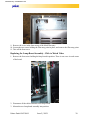
9. Remove the cover in the front on top of the black film entry.
10. Loosen the two screws holding the film entry point in place; and remove the film entry point.
11. Take off the front cover.
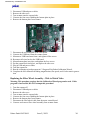
Replacing the Lamp Board Assembly - Click to Watch Video
1. Remove the four screws holding the lamp board in position. There is one screw in each corner
of the board.
2. Disconnect all the cables attached to the lamp board.
3. Mount the new lamp board assembly into position.
Pakon Part#124794-D
June 5, 2003
31
Distributed by: minilablaser.com
4. Attach all cables to the lamp board.
5. Mount the lamp board assembly back in to place.
6. Replace all covers.
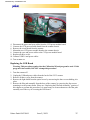
Replacing the Motor Control Board - Click to Watch Video
Warning: This procedure requires that the Calibration Wizard program be used. If this
program is inaccessible, DO NOT attempt this procedure!
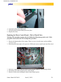
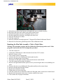
1. Remove the bottom plate of the scanner. There is a screw in each corner, and two phillips
screws as well.
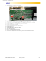
2. Removing the bottom plate will expose the USB board, motor control board, and filter wheel.
3. Each wire connector is labeled with the board it should connect to, and which pin block.
4. Disconnect each cable from the motor control board.
5. Remove all the screws holding the motor control board in place.
Pakon Part#124794-D
June 5, 2003
32
Distributed by: minilablaser.com
6. Mount the new motor control board into place.
7. Plug in all cables.
8. Mount bottom plate into place.
9. Connect USB and power cables, and turn scanner on.
10. In the calibration wizard, run the “Film Track Test” before attempting a scan. Repeat if necesary.
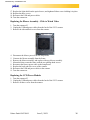
Replacing the Lamp Holder - Click to Watch Video
1.
2.
3.
4.
Turn the scanner off.
Unplug the USB and power cables from the back of the F-235 scanner.
Remove the side and back covers from the scanner.
Allow lamp to cool down before attempting to replace the lamp holder.
5. Remove the light bulb from the lamp holder.
6. Disconnect the lamp holder power cable from the lamp board.
7. Unscrew the four screws that mount the lamp holder to the scanner frame.
8. Mount the new lamp holder into place, and screw in the four screws.
9. Insert light bulb into lamp holder.
10. Re-connect the lamp holder power cable in the lamp board.
11. Replace the back and side covers.
12. Plug in the USB and power cables.
13. Turn scanner on.
Replacing the USB Board
Warning: This procedure requires that the Calibration Wizard program be used. If this
program is inaccessible, DO NOT attempt this procedure!
1. Turn the scanner off.
Pakon Part#124794-D
June 5, 2003
33
Distributed by: minilablaser.com
2.
3.
4.
5.
6.
Disconnect USB and power cables.
Remove the side cover.
Turn scanner onto the exposed side.
Unscrew the four screws holding the bottom plate in place.
Remove the bottom plate from scanner.
7. Disconnect the wires attached to the USB board.
8. Unscrew the USB board from the scanner frame.
9. Mount new USB board onto frame, and tighten all the screws.
10. Reconnect all wires back to the USB board.
11. Mount bottom plate into place, and tighten the four screws.
12. Put the scanner back into place, and replace the side cover.
13. Plug in USB and power cables.
14. Turn the scanner on.
15. Run the calibration wizard program in C:\Program Files\Pakon\Calibration Wizard\.
16. Complete the full calibration including magnification, film speed, and 64 color matrix generation.
Replacing the Filter Wheel Assembly - Click to Watch Video
Warning: This procedure requires that the Calibration Wizard program be used. If this
program is inaccessible, DO NOT attempt this procedure!
1.
2.
3.
4.
5.
6.
7.
8.
Turn the scanner off.
Disconnect USB and power cables.
Remove the side cover.
Turn scanner onto the exposed side.
Unscrew the four screws holding the bottom plate in place.
Remove the bottom plate from scanner.
Disconnect the filter wheel cable from the motor control board.
Unscrew and remove filter wheel assembly from scanner frame.
Pakon Part#124794-D
June 5, 2003
34
Distributed by: minilablaser.com
9. Mount the new filter wheel in place and tighten the screws to hold it in place.
10. Reconnect the filter wheel cable to the motor control board.
11. Mount bottom plate into place, and tighten the four screws.
12. Put the scanner back into place, and replace the side cover.
13. Plug in USB and power cables.
14. Turn the scanner on.
15. Run the calibration wizard program in C:\Program Files\Pakon\Calibration Wizard\.
16. Run the 64 color matrix generation portion of the calibration wizard.
Replacing the Film Path Assembly - Click to Watch Video
Warning: This procedure requires that the Calibration Wizard program be used. If this
program is inaccessible, DO NOT attempt this procedure!
1.
2.
3.
4.
5.
6.
7.
8.
9.
Turn the scanner off.
Unplug the USB and power cables from the back of the F-235 scanner.
Remove all three covers.
Turn scanner onto the exposed side.
Unscrew the four screws holding the bottom plate in place.
Remove the bottom plate from scanner.
Disconnect all film path assembly cables from the motor control board.
Turn the scanner into its proper orientation.
Remove the light shield from the optical tower by unscrewing the three screws holding it in
place.
10. Unscrew the four screws holding the film path assembly on the scanner frame.
11. Remove the film path from the scanner.
12. Replace the film path assembly.
13. Tighten the four screws into place.
14. Turn the scanner onto its side and reconnect all film path cables on the motor control board.
15. Replace the bottom plate, and secure it in place with the four screws.
16. Turn scanner into its proper orientation.
Pakon Part#124794-D
June 5, 2003
35
Distributed by: minilablaser.com
17. Replace the light shield on the optical tower, and tighten all three screws holding it in place.
18. Replace the three covers.
19. Reconnect the USB and power cables.
20. Turn the scanner on.
Replacing the Blower Assembly - Click to Watch Video
1. Turn the scanner off.
2. Unplug the USB and power cables from the back of the F-235 scanner.
3. Remove the side and back covers from the scanner.
4. Disconnect the blower power from the lamp board.
5. Unscrew the blower assembly from the frame.
6. Remove the blower assembly, and replace with new blower assembly.
7. Mount the blower onto the frame with the two phillips head screws.
8. Reconnect the blower power cable to the lamp board.
9. Replace the back and side covers of the scanner.
10. Reconnect the USB and power cables to the scanner.
11. Turn the scanner on.
Replacing the CCD Power Module
1. Turn the scanner off.
2. Unplug the USB and power cables from the back of the F-235 scanner.
3. Remove all three covers from the scanner.
Pakon Part#124794-D
June 5, 2003
36
Distributed by: minilablaser.com
4. Disconnect the power and sync cables from the CCD power module board.
5. Unscrew the CCD power module board from the scanner chassis.
6. Remove the circuit board from the scanner.
7. Mount the new CCD power module board to the scanner chassis.
8. Connect the sync and power cables to the CCD power module board.
9. Replace all three covers.
10. Connect USB 2.0 and power cables.
11. Turn scanner on.
Replacing the LED Board
Warning: This procedure requires that the Calibration Wizard program be used. If this
program is inaccessible, DO NOT attempt this procedure!
1.
2.
3.
4.
Turn the scanner off.
Unplug the USB and power cables from the back of the F-235 scanner.
Remove all three covers from the scanner.
Remove the light shield from the optical tower by unscrewing the three screws holding it in
place.
5. Remove the film path assembly from the base of the scanner, by removing the four screws
mounting it to the scanner frame. Please see “Replacing the Film Path Assembly” portion of
this chapter to perform this procedure. It is unnecessary to do more than move the film path
assembly out of the way of accessing the LED board.
Pakon Part#124794-D
June 5, 2003
37
Distributed by: minilablaser.com
6. The LED board should now be exposed.
7. Unplug the thin ribbon cable from the right side of the LED board.
8. Unscrew the one screw mounting the LED board to the illumination assembly.
9. Replace the defective LED board with a new LED board.
10. Replace the film path assembly.
11. Replace the light shield on the optical tower.
12. Replace the covers.
13. Connect the USB 2.0 and power cables.
14. Turn the scanner “On.”
15. Run the Calibration Wizard program.
16. Perform the “Magnification Calculation” portion of the calibration wizard.
Pakon Part#124794-D
June 5, 2003
38
Distributed by: minilablaser.com
Setup1300
Setup1300.exe is an important diagnostic tool used to verify basic hardware functionality.
This program is accessible in the Pakon software directory, which will vary depending on the client interface software in use. Generally it is in C:\Program Files\Pakon\Setup1300.exe.
This program should be used to ensure that the following hardware is functioning properly:
Hardware
Test Function
Filter Wheel
Spinning and stopping in proper positions
APS/35MM Gate
Opening and Closing
Lens Stepper
Moving up and Down
CCD Stepper
Moving up and Down
Motor
Moves forwards and backwards
Lamp
Turns on and Off
Each button reports its function when the mouse cursor sits on top of it.
Pakon Part#124794-D
June 5, 2003
39
Distributed by: minilablaser.com
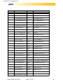
Command
Function
Command
Function
g
start filmstrip motor
“
move right cursor -100
h
stop filmstrip motor
L
move right cursor -10
f
move filmstrip forward
l
move right cursor -1
r
move filmstrip reverse
;
move right cursor +1
@
gain/offset correction
:
move right cursor +10
!
fixed pattern correction
‘
move right cursor +100
+
focus calibration
HI
lamp high
magnification distance
LO
lamp low
<
move CCD down 100
OFF
lamp off
{
move CCD down 10
[
move CCD down 1
Rese
lamp reset
]
move CCD up 1
&
skew calibration
}
move CCD up 10
REG
load calibration data
>
move CCD up 100
SNS
calibrate insertion sensors
I
move left cursor -100
NEG
set negative filter
J
move left cursor -10
POS
set positive filter
j
move left cursor -1
BLK
set block filter
k
move left cursor +1
MT1
stepper/drive life test
K
move left cursor +10
MT2
Film gate/filter wheel life test
i
move left cursor +100
Lens Test
lens stepper validation test
x
move lens down 100
CCD Test
CCD stepper validation test
c
move lens down 10
APS
set filmguides to APS
v
move lens down 1
35MM
set filmguides to 35MM
b
move lens up 1
IR ON
Digital ICE on
n
move lens up 10
IR Off
Digital ICE off
m
move lens up 100
“
move right cursor -100
Pakon Part#124794-D
calculate film sizes
June 5, 2003
40
Distributed by: minilablaser.com
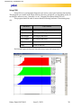
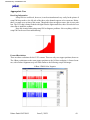
Appropriate Uses
Deceiving Information
Setup1300 is a useful tool, however, it can be misunderstood very easily. In the picture of
setup1300 shown above, the left side of the three color channels appears to be erroneous. Below
there is a small cross-section of this errata. Though this does not appear correct, this is not a problem. The CCD chip is being flooded with light from the light transfer bar, this will not be the case
when film is inside the scanner.
Keep this in mind when using setup1300 to diagnose problems. Not everything visible in
setup1300 can be used for troubleshooting.
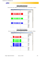
Focused Resolutions
There are three resolutions for the F-235 scanner. There are only two stepper positions, however.
The 4 Base resolution uses the same stepper positions as the 16 Base resolution. A focused scanner, with a Pakon Alignment strip will look similar to the following setup1300 images.
16 Base 35MM Color Negative
Pakon Part#124794-D
June 5, 2003
41
Distributed by: minilablaser.com
16 Base 35MM Color Reversal
Note how the color channels are all lower than that of the ‘color negative’ display.
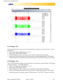
8 Base 35MM Color Negative
Note how the 8 Base scan uses a smaller portion of the CCD chip than 16 Base.
Pakon Part#124794-D
June 5, 2003
42
Distributed by: minilablaser.com
8 Base 35MM Color Reversal
8 Base Color Reversal color channels should be lower than 8 BaseColor Negative.
Lens Stepper Test
The lens test function is a great way to ensure that the lens stepper is moving correctly. To use
this function:
1. Move lens stepper to 2000 using the ‘x’ key.
2. Click on the “LENS TEST” button.
3. The lens stepper will move one step at a time until it reaches the home position.
4. Setup1300 will report the number of steps it took to reach the home position. This number
should be equal to the stepper position (2000) before the “LENS TEST” button was clicked.
CCD Stepper Test
The CCD Test function, like the Lens Test function, is a great way to ensure that the CCD stepper
is moving correctly. To use this function:
1. Move CCD stepper to 1200 using the ‘<’ key.
2. Click on the “CCD TEST” button.
3. The CCD stepper will move one step at a time until it reaches the home position.
4. Setup1300 will report the number of steps it took to reach the home position. This number
should be equal to the stepper position (1200) before the “CCD TEST” button was clicked.
Pakon Part#124794-D
June 5, 2003
43
Distributed by: minilablaser.com
Lens Positioning Verification
This will test that the lens is properly aligned. If the scanner fails, the scanner will have to be serviced at a service depot.
1. Click on the “@” button.
2. Select 8 Base 35 Color Negative.
3. Click the “LO” button to turn the lamp into low power mode.
4. Click on “NEG” to move the filter wheel to the negative position.
5. Insert a clear piece of color negative film.
6. Apply light pressure to each side of the lens, and make sure that none of the color channels
drop.
APS/35MM Film Gate Verification
This test will ensure that the film gate is opening and closing properly.
1. Click on the “APS” button.
2. Observe the film gate close to the APS position.
3. Click the “35MM” button.
4. Observe the film gate open to the 35MM position.
5. Repeat this procedure ten times to verify functionality.
Drive Motor Verification
This test will ensure that the motor is functioning properly.
1. Click the “g” button.
2. Observe the motor start.
3. Click the “h” button.
4. Observe the motor stop.
5. Repeat this ten times to verify functionality.
Lamp Verification
This test will ensure that the motor is functioning properly.
1. Click the “HI” button.
2. Observe the lamp turn on.
3. Click the “LO” button.
4. Observe the lamp dim.
5. Click the “OFF” button.
6. Observe the lamp turn off.
Filter Wheel Verification
This test will ensure that the filter wheel is moving into the three different positions properly.
1. Click the “HI” button.
2. The lamp should turn on.
3. Click the “NEG” button.
4. Observe the color of the illuminator turn cyan.
5. Click the “POS” button.
Pakon Part#124794-D
June 5, 2003
44
Distributed by: minilablaser.com
6. Observe the color of the illuminator turn white.
7. Click the “BLK” button.
8. There should be no light shining from the illuminator.
Pakon Part#124794-D
June 5, 2003
45
Distributed by: minilablaser.com
Troubleshooting
Basics
The scanner will not work properly unless the scanner is turned on after Windows 2000
has finished the loading process. Ensure this is done before attempting more advanced troubleshooting.
Error Logs
There are four primary error logs generated by the scanner software. These error logs are a
very important tool to determine the cause of any reported error codes. When contacting technical
support, it is advisable to provide these logs to ensure a more informed response.
These logs can be located in C:\Program Files\Pakon\TLA COM Server.
These logs include:
PakonErrorLogMain
Logs any errors associated with scanner communications with the host PC.
PakonErrorLogScan
Logs any errors associated with the scan process.
PakonErrorLogSave
Logs any errors associated with the save process.
PakonErrorLogPI
Logs any errors associated with the color correction process.
Pakon Error Log Main
Device IO Control Errors:
EC_WIN_DeviceIoControl A device attached to the system is not functioning.
Type xxx, PktLen yyy, Address <device code>
The “device code” will be in hexadecimal. Refer to the “Device Code” table below to
determine what piece of hardware is reporting an error. Attempt to reload the firmware for the
failing boards using MFCTest.exe.
Hardware Fault Codes:
EC_HardwareFault <hardware fault codes>
The “hardware fault codes” will be in decimal, convert them to hexadecimal and refer to
the “Hardware Fault Codes” table below to determine the meaning of the fault codes. Be sure that
the scanner has the grounding wires installed before attempting to find the meaning of the fault
code(s). Also try re-loading the firmware of the problem device.
Pakon Part#124794-D
June 5, 2003
46
Distributed by: minilablaser.com
Skipping Lamp Warm-up and Calibrations
It is useful to have the ability to disable the lamp warm-up and calibrations during startup.
This should only be done for troubleshooting purposes only. Using these options can cause erratic
image quality issues. Use the registry editor to disable these two registry keys:
[HKEY_LOCAL_MACHINE\SOFTWARE\Pakon\PSI F-235\Scanner Settings]
StartupCalibrationSelection=1
[HKEY_LOCAL_MACHINE\SOFTWARE\Pakon\TLA\Scan\Test]
UseLampColdStart=0
Error Code 1002 or 1006
These two error codes relate to the speed of the computer hardware. Verify that the host
PC meets the requirements outlined in the “Specifications” chapter.
Error Codes 126, 127, 128, and 129
Run the focus correction in the client software.
Error Code 1003 (Lost Sync)
Attach grounding straps to film track. Contact Pakon technical support for further information.
Error Code 3016
Verify that there is an N: partition that is left unformatted, and it is a minimum of 5GB.
Error: EC_PFS_FileSystemExists (Error Code 3001)
The N: is formatted. The N: partition cannot be formatted. Re-create this partition using
the instructions in the “Hard Disk Configuration” chapter of this manual.
Error Code 3013
Buffer drive, (N:) is bad. Replace this drive partition.
Scanner will not stop scanning.
Change this registry key:
"HKEY_LOCAL_MACHINE\SOFTWARE\Pakon\TLA\Scan\Test\DriverSimultaneousPackets" to 1.
Error 178: EC_WIN_SetProcessWorkingSetSize
The operator does not have Administrative privileges, or does not have enough available
RAM. 512MB is required, as outlined in the “Specifications” chapter.
Pakon Part#124794-D
June 5, 2003
47
Distributed by: minilablaser.com
1.
2.
3.
4.
5.
6.
7.
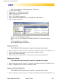
Also, try increasing the ‘scheduling priority’ for all users:
Go to the Control Panel.
Double-click on “Administrative Tools.”
Double-click on “Local Security Policy.”
Select “Local Policies.”
Select “User Rights Assignment.”
Select “Increase Scheduling Priority” on the right side of the window.
Add “Everyone” to the list.
Decrease the “Ringtail Bytes” as well:
[HKEY_LOCAL_MACHINE\SOFTWARE\Pakon\PSI F-235\Scanner Settings]
Set:
DriverRingTailBytes to 0x800000
ProcessedRingTailBytes to 0x400000.
Images Stretched
The Calibration Wizard program is required to perform this procedure.
1.
2.
3.
4.
Run the calibration wizard, located in C:\Program Files\Pakon\Calibwiz235\Calibwiz235.exe.
Click on the button on the bottom left corner of the calibration window.
Select “Film Speed Adjustment.”
Follow the on-screen instructions to set the motor speed and framing adjustment.
Images out of Focus
The Calibration Wizard program is required to perform this procedure.
1. Run the calibration wizard, located in C:\Program Files\Pakon\Calibwiz235\Calibwiz235.exe.
2. Run the “Magnification” steps in the calibration wizard.
Images not Framed Properly
The Calibration Wizard program is required to perform this procedure.
1. Run the calibration wizard, located in C:\Program Files\Pakon\Calibwiz235\Calibwiz235.exe.
Pakon Part#124794-D
June 5, 2003
48
Distributed by: minilablaser.com
2. Click on the button on the bottom left corner of the calibration window.
3. Select “Motor Speed.”
4. Follow the on-screen instructions to set the motor speed and framing adjustment.
Image is out of focus in part of frame
The Calibration Wizard program is required to perform this procedure.
If this is a problem on every roll of film, the ‘Tilt Adjustment’ will need to be run in the
calibration wizard.
The problem is that the CCD chip is not parallel with the film--part of the CCD chip is
focused, and part of it is out of focus. The ‘tilt adjustment’ will level the CCD board and put it in
parallel with the film and light transport.
Scanning stops after one frame
The scanner calibrations may need to be re-done every two hours because the lamp temperature may vary throughout the day.
DX code reading is not working
The film track should be cleaned every two weeks to ensure proper DX code reading. This
procedure can be found in the “Operator Service” chapter in this manual. When finished, run the
'Track Test” calibration in the client interface program.
This requires a four frame strip of film with DX codes on it. Be sure to insert the film
emulsion up, starting with the lowest number first, with the DX codes to the back of the scanner.
If DX code reading does not improve after cleaning and running the client film track test,
the film track test should be run using the Calibration Wizard program.
Black images
Black images are usually caused by one of two problems. Firstly, the light shield has a
removable piece for cleaning the lens. The screw holding this light shield in place is a thumb
Pakon Part#124794-D
June 5, 2003
49
Distributed by: minilablaser.com
screw, and can come loose if shaken during shipment. Ensure this light shield is properly
mounted and is not loose.
A fuse on the LED board can be damaged causing this board to flood the CCD board with
infra-red light and will cause scanned images to appear black. To test this, unplug the LED cable
on either the LED board, or the lamp board.
Removing this cable will remove the defect channel from being used. If the scanner scans
properly after removing this defect channel, the LED board will need to be replaced.
‘1155: File C:\INSTMSIW.EXE was not found’ error when installing PSI
The Windows Installer program is not installed on the host PC. Download the installer
from Microsoft’s website, or from www.pakon.com.
http://www.microsoft.com/downloads/release.asp?releaseid=32832&NewList=1
Noritsu2611.txt Error Log File
PSI will create an error log file in the C:\Program Files\Pakon\PSI\IQ\Logs folder to
report any errors in connecting to a Noritsu 2611 printer.
There are three error levels--one, two, and three. A level one error is informational, reportin that the printer is warming up for example. A level two error is a warning, reporting that the
water tank needs to be filled or similar such errors. A level three error is reporting a failure in
connecting to the Noritsu 2611 printer.
Pakon Part#124794-D
June 5, 2003
50
Distributed by: minilablaser.com
The Noritsu needs to be turned on, with a SCSI cable connected between the printer and
the PC prior to the PC being booted, along with PSI 1.3 or above, and the printer must be in
“AUX2” mode for PSI to be able to print to a 2611 printer.
Pakon Part#124794-D
June 5, 2003
51
Distributed by: minilablaser.com
Regulatory Information
Warning:
This is a class A product. In a domestic environment this product may cause radio interference in which case the user may be required to take adequate measures.
Note:
This equipment has been tested and found to comply with the limits for a Class A digital
device, pursuant to part 15 of the FCC rules. These limits are designed to provide reasonable protection against harmful interference when the equipment is operated in a commercial environment. This equipment generates, uses and can radiate radio frequency energy and, if not installed
and used in accordance with the instruction manual, may cause harmful interference to radio communications. Operation of this equipment in a residential area is likely to cause harmful interference in which case the user will be required to correct the interference at his own expense.
Note:
Taiwan:
Pakon Part#124794-D
June 5, 2003
50
Distributed by: minilablaser.com
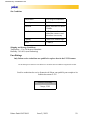
Site Conditions
Temperature
59-85 degrees Fahrenheit
Humidity
30-75% (non-condensing)
Vibration
Not to Exceed 0.05G RMS
5-200Hz
Ventilation
A 4” clearance above and
behind the scanners ventilation duct is necessary
Lighting
<1000 LUX ambient light
Noise
< 70db(A)
Shipping and Storage Conditions
Temperature: -13 to 140 degrees Fahrenheit
Humidity: 30%-90% (non-condensing)
Fuse Ratings
Only Pakon service technicians are qualified to replace fuses in the F-235 Scanner.
Die Sicherungen im Scanner F-235 dürfen nur von Pakon-Servicetechnikern ausgetauscht werden.
Seuls les techniciens du service d'entretien de Pakon sont qualifiés pour remplacer les
fusibles du scanner F-235.
Factory Fuse Rating
3 Amps, 250V
Pakon Part#124794-D
June 5, 2003
51
Distributed by: minilablaser.com
Important Part Numbers
Part Number
Pakon Part#124794-D
Description
123677
Motor Control Board
123681
USB Board
123685
CCD Power
123687
Lamp Mod Board
123689
Sensor Board
123691
LED Board (Digital ICE)
123705
Wheel Rotary Filter
123784
Sensor, DX Code
123816
Filter, Air
123817
Holder, Lamp
123819
Cooling Fan
124803
Blower Assembly
124558
Filter Wheel Assembly
124560
Film Path Assembly
123834
O-Ring Drive
123840
Power Supply
123841
Bulb
123886
Mount Fan, Light Board
123936
Cable Data
124805
Lamp Holder Assembly
123938
CCD Cable
123939
USB 2.0 Cable 6ft.
124515
Lamp Board Fan Assembly
124516
CCD Cable Power
124511
Cover, Film Entrance
June 5, 2003
52
Distributed by: minilablaser.com
Index
Symbols
‘tilt’ adjustment 5
A
APS film 2
APS LED 17
APS/35MM Film Gate Verification 44
APS/35MM Gate 39
B
BIOS Configuration 15
Black images 49
C
Calibration 16
CCD assembly 4
CCD Stepper 39
CCD Stepper Test 43
Cleaning Illumination with Cotton Swab 21
Cleaning the Illumination with Compressed Air 19
Connection Diagram 8
Contents of Box 2
D
Device IO Control Errors 46
Digital ICE 17
Drive Motor Verification 44
driver software 14
Dust cleaning of illumination 19
DX code reading is not working 49
DX codes 16
DX Sensors 6
E
EC_WIN_SetProcessWorkingSetSize 47
Error
EC_PFS_FileSystemExists 47
Error 161 47
Error Code 1002 47
Error Code 1002 or 1006 47
Error Code 1006 47
Error Code 145 47
Error Code 3001 47
Error Code 3013 47
Error Codes 47
Error Codes 126, 127, 128, and 129 47
Error Logs 46
Pakon Part#124794-D
June 5, 2003
53
Distributed by: minilablaser.com
F
Fan filter 25
Film Gate Change 16
Film Guides 6
film track 4
Film Types and Variations 2
Filter Wheel 39
filter wheel 6
Filter Wheel Verification 44
Focus 16
Format Change 16
Fuse Ratings 51
H
Hardware Fault Codes 46
I
Image is out of focus in part of frame 49
Images not Framed Properly 48
Images out of Focus 48
Images Stretched 48
Installing 13
Installing the F-235 13
L
Lamp 39
Lamp Verification 44
LED Board 37
LED board 50
LED Indicator Lights 17
Lens 5
lens alignment fixture 5
Lens Positioning Verification 44
Lens Stepper 39
Lens Stepper Test 43
Light Bulb Replacement 22
light shield 49
Light Source 2
M
Minimum Host Computer Specifications 1
Motor 39
motor control 5
Motor Speed 48
Mounted slides 2
N
Noritsu 50
Noritsu 2611 50
Noritsu2611.txt 50
Pakon Part#124794-D
June 5, 2003
54
Distributed by: minilablaser.com
O
Operation 16
optical tower 4
P
Pakon Error Log Main 46
PakonErrorLog 46
PCI Latency Timer 15
power cord 13
Power LED 17
Powering On 16
R
Regulatory Information 50
Removing Covers 29
Replacing the Blower Assembly 36
Replacing the CCD Power Module 36
Replacing the Fan Filter 28
Replacing the Film Path Assembly 35
Replacing the Filter Wheel 34
Replacing the Lamp Board 31
Replacing the Lamp Board Fan 31
Replacing the Lamp Holder 33
Replacing the LED Board 37
Replacing the Motor Control Board 32
Replacing the USB Board 33
Resolutions 2
S
Scanner Theory 4
Scanner will not stop scanning. 47
Scanning stops 49
SCSI BIOS 15
Service and Repair 29
Setup1300 39
skew 4
Skipping Lamp Warmup and Calibrations 47
Status LED 17
Surface Cleaning 25
T
Tilt Adjustment 49
Track Test 49
U
USB 2.0 hub 1
USB Board 6
W
Windows Customizations 15
Pakon Part#124794-D
June 5, 2003
55