1
RocketStor 6422TS
User Manual
Jul 23nd, 2015
Revision 1.01
HighPoint Technologies, Inc.
1
Copyright
Copyright © 2015 HighPoint Technologies, Inc. This document contains materials protected by
International Copyright Laws. All rights reserved. No part of this manual may be reproduced,
transmitted or transcribed in any form and for any purpose without the express written
permission of HighPoint Technologies, Inc.
Trademarks
Companies and products mentioned in this manual are for identification purpose only. Product
names or brand names appearing in this manual may or may not be registered trademarks or
copyrights of their respective owners. Backup your important data before using HighPoint's
products and use at your own risk. In no event shall HighPoint be liable for any loss of profits,
or for direct, indirect, special, incidental or consequential damages arising from any defect or
error in HighPoint's products or manuals. Information in this manual is subject to change
without notice and does not represent a commitment on the part of HighPoint.
Notice
Reasonable effort has been made to ensure that the information in this manual is accurate.
HighPoint assumes no liability for technical inaccuracies, typographical, or other errors
contained herein.
FCC Part 15 Class B Radio Frequency Interference statement
This equipment has been tested and found to comply with the limits for a Class B digital device,
pursuant to part 15 of the FCC Rules. These limits are designed to provide reasonable
protection against harmful interference in a residential installation. This equipment generates
uses and can radiate radio frequency energy and, if not installed and used in accordance with
the instructions, may cause harmful interference to radio communications. However, there is no
guarantee that interference will not occur in a particular installation. If this equipment does
cause harmful interference to radio or television reception, which can be determined by turning
the equipment off and on, the user is encouraged to try to correct the interference by one or
more of the following measures:
Reorient or relocate the receiving antenna.
Increase the separation between the equipment and receiver.
Connect the equipment into an outlet on a circuit different from that to which the receiver is
connected.
Consult the dealer or an experienced radio/TV technician for help.
Modifications not expressly approved by the manufacturer could void the user’s authority to
operate the equipment under FCC rules.
This device complies with part 15 of the FCC Rules. Operation is subject to the following two
conditions: (1) this device may not cause harmful interference, and (2) this device must accept
any interference received, including interference that may cause undesired operation.
European Union Compliance Statement
This Information Technologies Equipment has been tested and found to comply with the
following European directives:
European Standard EN55022 (1998) Class B
European Standard EN55024 (1998)
2
Table of Contents
Product Overview ................................................................................................................. 6
Kit Contents............................................................................................................................ 6
Section 1: Hardware Installation ........................................................................................ 8
Preparing the Enclosure .........................................................................................................8
Preparing the HBA (Host Bus Adapter) ...............................................................................8
Connecting the HBA with the Enclosure ............................................................................9
LED Activity ............................................................................................................................ 11
Section 2: Drivers ................................................................................................................ 12
Installing Drivers on an Existing Operating System ..................................................... 12
Checking your Driver Version............................................................................................ 18
Loading the Drivers onto a Bootable Array .................................................................... 20
Updating the Drivers ............................................................................................................ 20
Uninstalling the Drivers ...................................................................................................... 21
Section 3: Navigating RocketRAID 4522 BIOS Utility (PC only) ............................... 23
System Tab ............................................................................................................................. 24
Disk Tab .................................................................................................................................. 25
Initializing disks ................................................................................................................ 26
Adding disks to spare pool............................................................................................. 26
Unplugging Disks .............................................................................................................. 27
Turn on/off disk write Cache......................................................................................... 27
Array Tab ................................................................................................................................ 27
Creating an Array .............................................................................................................. 28
Verifying your array ......................................................................................................... 30
Setting Boot Array ............................................................................................................. 30
Controller Tab ....................................................................................................................... 30
Window Tab ........................................................................................................................... 32
Section 4: BIOS/Firmware Updates ................................................................................. 32
Using the WebGUI to update BIOS/Firmware ................................................................. 33
Using a Bootable USB to update BIOS/Firmware ........................................................... 33
Section 5: Navigating the HighPoint WebGUI ............................................................... 34
Installing HighPoint WebGUI .............................................................................................. 35
How to Login HighPoint WebGUI....................................................................................... 37
Global Tab .............................................................................................................................. 40
Viewing HBA Properties................................................................................................... 40
3
Viewing Storage Properties ............................................................................................. 41
Physical Tab ........................................................................................................................... 41
Updating BIOS/Firmware................................................................................................. 42
Obtaining Physical Device Information ....................................................................... 43
Logical Tab ............................................................................................................................. 44
Creating an Array .............................................................................................................. 45
Adding Spare Disks .......................................................................................................... 50
Obtaining Logical Device Information.......................................................................... 50
Normal Status .................................................................................................................... 51
Critical Status..................................................................................................................... 52
Disabled Status .................................................................................................................. 53
Expanding an Existing Array .......................................................................................... 53
Setting Tab ............................................................................................................................. 56
System Settings ................................................................................................................. 56
Password Setting ............................................................................................................... 58
Changing your WebGUI password ................................................................................. 58
Recovering your WebGUI password .............................................................................. 58
Email Setting ...................................................................................................................... 58
Recover Tab ............................................................................................................................ 60
How to Backup your Recover List ................................................................................. 60
How to Reload your Backup Recover List.................................................................... 61
Event Tab ................................................................................................................................ 61
Table 1. Event Log Icon Guide ........................................................................................ 61
SHI (Storage Health Inspector) ........................................................................................... 62
How to Enable SMART Monitoring ................................................................................ 62
How to Change HDD Temperature Threshold ........................................................... 63
How to Use the Health Inspector Scheduler ............................................................... 64
How to Create a New Verify Task.................................................................................. 64
Section 6: Formatting the RAID Volumes ...................................................................... 65
Section 7: Troubleshooting ............................................................................................... 69
Handling Critical Arrays...................................................................................................... 70
Rebuilding Stops Due to Bad Sectors ........................................................................... 70
Critical array becomes disabled when you removed faulty disk ........................... 71
Handling Disabled Arrays ................................................................................................... 71
Your PC hangs when card is installed.............................................................................. 72
Help ........................................................................................................................................ 73
4
Table 2. WebGUI Icon Guide ............................................................................................... 74
Table 3. RAID Level Reference Guide ............................................................................... 76
HighPoint Recommended List of Hard Drives ............................................................... 77
Contacting Technical Support ........................................................................................... 77
5
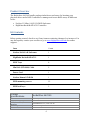
Product Overview
The RocketStor 6422AS bundle package includes an enclosure for housing your
physical drives and a RAID Controller to manage and create RAID arrays of different
levels.
NetStor 2U 8-Bay SAS/SATA JBOD Enclosure
HighPoint RocketRAID 4522 Controller
Kit Contents
Before getting started, check to see if any items are missing, damaged, or incorrect. For
any discrepancy contact your reseller or go to www.highpoint-tech.com for online
support.
Item
Count
NetStor NA341A-R Enclosure
1
HighPoint RocketRAID 4522
1
HDD Trays
8
Mini-SAS (SFF-8088) Cable
2
Power Cord
1
NetStor Manual CD-ROM
1
HDD mounting screws
32
HDD lock keys
2
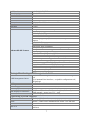
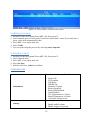
Feature
Specifications
Form Factor
Host Port
RAID Controller /Bus
Interface
I/O Storage Processor
Onboard Cache
RocketStor 6422AS
2U, 8-Bay Rackmount Enclosure
2x Mini-SAS
RocketRAID 4522 / PCIe 2.0 x8
RAID-On-Chip Onboard
512MB DDR 3 Cache Memory with ECC Protection
6
RAID Level
Max. Capacity
Number Of drives
Drive Interface
Drive Form Factor
Chassis Material
Dimension
Weight
Warranty
UPC
Advanced RAID Features
0, 1, 5, 6, 10, 50, JBOD
Up to 64 TB
Up to 8
SAS, SATA
3.5" & 2.5"
Heavy-duty cold-rolled steel housing
18(D)× 19(W)× 3.5(H) inches
37.43 lbs.
2 Years
643653642212
Configurable RAID Block Size up to 1MB
Flash ROM for Upgradeable Firmware
DV Mode Technology
Storage Health Inspector
Redundant RAID Configurations
BIOS PnP (plug and play) and BBS (BIOS boot specification)
support
Bootable RAID Array
EFI BIOS for Mac Platform
NVRAM for Write Journaling
Battery Backup unit retains data when power outage occurs
Multiple RAID Partitions supported
Online Array Roaming
Online RAID Level Migration (ORLM)
Online Capacity Expansion (OCE)
RAID Initialization Background/Foreground/Quick
Global Hot Spare Disk support
Automatic and configurable RAID Rebuilding Priority
Disk Format compatible: 512, 512e, 4Kn
Larger than 2 TB Drive and RAID Array support
Spin down Massive Arrays of Idle Disks support
Native Command Queuing
Staggered Drive Spin Up
Write Back and Write Through
Storage Monitoring and Management Suite
RAID Management Suites:
SMTP
Cooling Fan:
Power Supply
LED Display for Each Tray
LED Display For Enclosure
Alarm Buzzer
BIOS/Firmware configuration tool, Browser-Based management
tool
CLI (Command Line Interface) - scriptable configuration tool,
API package
Email Alert notification
Two 60× 60× 25 mm
Redundant 400 W 100-240 V AC, 50/60 Hz universal
White - Power-On Indicator / Blue -Busy (HDD Access) Indicator
POWER on LED (white / FAN normal – green; fail – red) /
TEMP( normal – green; over 55°C – red)
Buzzer beeping for Fan Failure or Temperature exceeds 50°C
Operating System Support
Windows
Linux
FreeBSD
Mac OS X
Windows / Windows Server
Linux: RedHat Enterprise, Open SuSE, Fedora Core, Debian,
Ubuntu / Linux Driver embedded into Kernel 3.9.4 and later
Yes
Mac OS X 10.6 and later (Driver embedded into Mac OS X 10.9
and later)
7
Operating Environment
Temperature
Relative Humidity
Certification
(operating) 5°C – 45°C
(non-operating) -40°C – 65°C
(operating) 8% – 90% RH (Non-condensing)
(non-operating) 5% – 95% RH (Non-condensing)
CE, FCC, RoHS
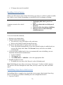
Section 1: Hardware Installation
This section covers the following topics:
1. Setting up the Enclosure
2. Setting up the HBA (Host Bus Adapter)
3. LED Activity
Preparing the Enclosure
You can refer to the NetStor 2U 8-Bay Rackmount Quick Installation Guide for details
on how to set up the enclosure.
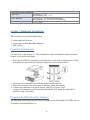
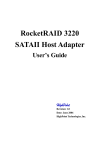
1. Take out the HDD tray and place your hard drive in the tray as shown below. Then
install the tray back into the enclosure. Repeat for all your hard drives.
2.
3.
4.
5.
Optional) Lock your HDD tray with the included disk tray key.
Place the enclosure on a server rack or another stable, flat surface.
Connect the enclosure to a power source with the AC Power Cord.
Connect the enclosure to the included RocketRAID 4522 using the mini-SAS to
mini-SAS cable (SFF-8088).
Preparing the HBA (Host Bus Adapter)
The following instructions describe how to prepare your RocketRAID 4522 HBA for use.
To install your RocketRAID 4522:
8
Important: Before installing the RocketRAID 4522 Controller, ensure that your system
is powered OFF.
1. Locate a PCIe 2.0 x8 slot (or compatible slot) on your PC motherboard.
Note 1: Refer to your PC manual for instructions on how to access your
motherboard.
Note 2: Refer to your motherboard manual for instructions on how to locate
your PCI Express slot.
2. Align the RocketRAID 4522 with the PCIe slot and push straight down until card is
fully seated.
3. Tighten the connection by fastening the RocketRAID bracket and enclosure
together.
A PCI-Express 2.0 x8 card is compatible with PCI-Express 2.0 x16 and PCI-Express 3.0
x16 slots.
Connecting the HBA with the Enclosure
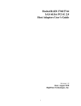
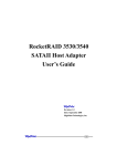
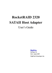
Figure 1. Enclosure Front Panel
9
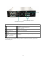
Figure 2. Enclosure Back Panel
Key
1 HDD Power LED
5 Temperature LED
GREEN- normal temperatures
RED – over 55°𝐶
2 HDD Status LED
6 Power Cord Receptacle
3 Mute Button : Resets
alarm
7 dual mini-SAS (SFF-8088) Connectors
4 FAN Status LED:
GREEN – normal status
RED – FAIL status
8 DB9 Connector (Connecting SGPIO signal for HDD fail
display)
Use the mini-SAS (SFF-8088) cables provided to connect the enclosure ports to the
RocketRAID ports.
10
LED Activity
The following information tells you how to interpret LED activity seen on the enclosure
and disk trays.
Present
Active
Failed
Identify
Disk Tray
WHITE
BLUE
N/A
N/A
Enclosure LEDs
WHITE
N/A
N/A
Fans LEDs
GREEN
RED
N/A
Temperature LEDs
GREEN
RED
N/A
Present – Indicates that the disk is present and available.
Active – Indicates the disk is performing disk I/O
Failed – Indicates disk failure (Not available for RS6422AS enclosure)
Identify – Identify LED is a setting that can be enabled in Physical > devices. This
setting will bring up a RED LED for the drive that is enabled for easy identification.
Identify LEDs are not available on the RS6422AS enclosure.
11
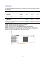
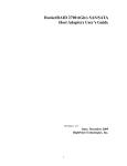
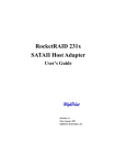
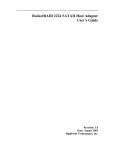
RocketRAID 4522 Key
PORT1
BEEP
mini-SAS (SFF-8088) Connection
Corresponds to channel 1-4
mini-SAS (SFF-8088) Connection
Corresponds to channel 5-8
Alarm/Beeper
J9
I2C Connector
J6
Battery Backup Unit (BBU) Connector
PORT2
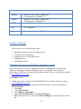
Section 2: Drivers
This section covers the following topics:
Installing drivers on your Operating System
Verifying driver installation
Loading drivers on a bootable array
Updating drivers
Uninstalling drivers
Installing Drivers on an Existing Operating System
Drivers provide a way for your operating system to communicate with your new
hardware. Updating to the latest drivers ensures your product has the latest
performance, stability, and compatibility improvements. Drivers are updated regularly
at www.highpoint-tech.com
For Windows Users:
1. Obtain latest driver software for RocketRAID 4522 Controller from our website
www.highpoint-tech.com
2. Take note the location you downloaded the driver file to, then open Windows
Device Manager.
Click Start
Click Control Panel
Click Hardware and Sound
Under Devices and Printer, Click Device Manager
Note: Alternatively, you can search Device Manager in your start menu search
bar.
12
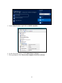
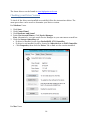
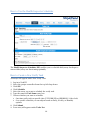
3. Under Other Devices, right click on RAID controller
4. On the drop down menu, click Update Driver Software…
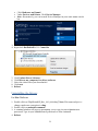
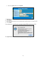
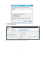
5. When prompted, select Browse my computer for driver software
13
6. Locate the driver files you downloaded and select them.
7. Press next and follow the on screen instructions
8. Reboot
For Mac Users:
HighPoint Mac Drivers have file extension .dmg; make sure the file extension for the
files you downloaded are the same.
1. Obtain latest driver online at www.hptmac.com
Navigate to your specific HBA controller page (Refer to How to View HBA
Properties to find model name)
14
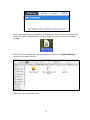
2. Once downloaded, locate the folder you downloaded the driver to and double click
on the file named “HighPointRR_###.dmg” Note: File name varies, but extension
is .dmg.
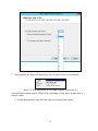
3. The file will be mounted onto the operating system, click on HighPointRR.pkg
located on the mounted drive.
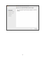
4. Follow the on-screen instructions.
15
5. Reboot computer
16
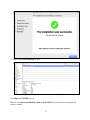
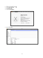
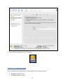
6. Make sure Driver Installed is Yes
Figure 3. Click Apple Icon > About this Mac... > System Report > PCI
For Linux and FreeBSD users:
Refer to the Driver Installation Guide and README files in each driver package for
steps to install.
17
The latest drivers can be found at www.highpoint-tech.com
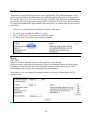
Checking your Driver Version
To check if the driver was installed successfully follow the instructions below. The
same procedure can be used to determine your driver version.
For Windows Users:
1.
2.
3.
4.
Click Start
Click Control Panel
Click Hardware and Sound
Under Devices and Printer, Click Device Manager
Note: Alternatively, you can search Device Manager in your start menu search bar.
5. Click the Storage controllers tab
If driver is installed it will show RocketRAID 4522 Controller,
If driver is not installed it will be located in Other devices as RAID Controller
Click Properties, then click the Driver Tab to find out the version installed.
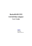
Figure 4. Driver version 1.3.14.0 for a RocketRAID 644LS
For Mac Users:
18
1.
2.
3.
4.
Click on the Apple Icon (
Click About this Mac
Click More Info
Click System Report
5. Select PCI Cards
Figure 5. Navigate to Apple Icon > About this Mac > System Report > PCI
19
Loading the Drivers onto a Bootable Array
Creating an array and then installing Windows OS onto the RAID configuration is a
bootable array. Since you cannot use the conventional method of installing drivers, the
drive must be loaded during Windows installation.
For Windows Users:
1. On first boot-up, press CTRL + H during the HighPoint RocketRAID splash screen
to enter the BIOS RAID creation utility.
2. Create the array you want to install your Windows Operating System onto
3. With the array created, download the RS6422AS drivers from www.highpointtech.com and load them onto a USB. You will need to locate the files when
prompted to load drivers during Windows Installation
4. Start Windows Installation.
5. When prompted Where do you want to install Windows? Click Load Driver
6. When prompted, click Browse
7. Browse to your connected USB and driver files you downloaded
8. Click OK, and once loaded, you will see a list of drivers detected.
9. Select the HighPoint driver file
10. Click Next, and you should see the RAID arrays you created
11. Select the RAID array and click next
12. Follow the Windows installation instructions to complete your installation
A bootable array differs for Mac users since there is no way to load the HBA drivers
during installation. The only way to create a bootable array would be to use 3rd party
software, and clone the bootable drive.
For Mac Users:
1. You must have an existing installation of the Mac operating system installed.
2. Set up the RS6422AS normally by
Setting up the hardware ()
Installing HighPoint RocketRAID 4522 driver and WebGUI
Creating an Array using the WebGUI
3. Once an array is created, the logical volume can be seen by your operating system
4. Use a 3rd party disk cloning tool to copy your bootable drive onto the logical drive
you just created.
Updating the Drivers
For Windows Users:
1. Obtain the latest driver files for RocketRAID 4522 from www.highpoint-tech.com
2. Open Windows Device Manager
Click Start
Click Control Panel
20
Click Hardware and Sound
Under Devices and Printer, Click Device Manager
Note: Alternatively, you can search Device Manager in your start menu search
bar.
3. Click the Storage controllers tab
4. Right click RocketRAID 4522 Controller
5.
6.
7.
8.
9.
Click Update Driver Software…
Click Browse my computer for driver software
Select the driver files you downloaded
Click next
Reboot
Uninstalling the Drivers
For Mac Platform:
1. Double click on “HighPointIOP_Mac_106_####.dmg” Note: File name subject to
change, make sure extension is .dmg.
2. Double click on uninstall.command
3. A terminal window will pop up prompting you to type in your administrator
password. Type in your administrator password to allow uninstall.
4. Reboot
21
Note: The file is flagged as an unidentified developer file on OSX. In order to open,
hold the Control key + click the file, then click open. A system prompt will appear;
read the prompt, then click open.
For Windows Platform:
1. Open Windows Device Manager
Click Start
Click Control Panel
Click Hardware and Sound
Under Devices and Printer, Click Device Manager
Note: Alternatively, you can search Device Manager in your start menu search
bar.
2. Click the Storage controllers tab
3. Right click RocketRAID 4520 SAS Controller
4. Click Uninstall
5. Reboot your PC for changes to take effect
22
Section 3: Navigating RocketRAID 4522 BIOS Utility (PC only)
HighPoint RocketRAID BIOS utility allows you to create, manage, and
maintain your RAID arrays without the need to install HighPoint WebGUI
application.
During boot up, you will see a RocketRAID splash screen prompting you to
press CTRL + H to enter the BIOS. The following keys will help you navigate
through the menus, find information, and make adjustments to your RAID
arrays.
Figure 6. RocketRAID Splash Screen. Press CTRL + H to enter BIOS
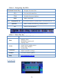
Figure 7. Default Screen upon entering BIOS.
23
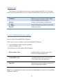
Table 1. Navigating the BIOS
Keyboard Arrow Keys
Navigate the menu bar
F10
Accesses the menu bar
TAB
Switches between windows
Enter
Make a selection
ALT + <highlighted key>
Spacebar
ESC
Selects Menu Item (Ex. System can be accessed with ALT + S
Make certain selections (eg. creating arrays)
Exits a selection menu
Figure 8. Snapshot of menu bar
Table 2. Menu Bar Key
System
Disk
Array
Controller
Exits the BIOS (ALT + X)
Displays disk Information
Initialize disks
Add disks to spare pool
Unplugs disks
Displays array information
Create/delete/unplug arrays
Verify array integrity
Set boot flag
Displays RAID controller information
Adjust controller settings
Window
View BIOS window panels
Help
www.highpoint-tech.com
System Tab
24
Press ALT + X to exit the BIOS.
Disk Tab
Access disk tab by navigating to disk and pressing enter, or press ALT + D.
Information
Initialize
Toggle Spare
Provides physical disk information:
Device Type: SATA or SAS
Model Number
Serial Number
Firmware Revision
Capacity (in sectors)
Read Ahead (on/off)
Write Cache (on/off)
TCQ
NCQ (on/off)
Spin up mode
Initializes selected disks
Adds selected disks to spare pool
25
Unplug
Turn on/off write cache
Rescan
Identify Disk
Ejects selected disks
toggles disk write cache ability
Triggers motherboard? to rescan
If applicable, will light up identify LED.
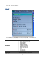
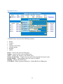
Initializing disks
First you must navigate to the disk panel. By default, you start on the disk panel.
1.
2.
3.
4.
5.
Press ALT + W to access Window tab
Select disk(s)
Use keyboard arrow keys to navigate and press enter to select desired disk(s)
Press ALT + D to activate disk tab
Select Initialize
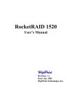
Figure 9. Four disks are slected and about to be initialized.
6.
7.
8.
9.
Press Enter
A prompt will warn you that data will be erased
Select Yes
Once initialized, you can proceed to create an array.
Adding disks to spare pool
26
1.
2.
3.
4.
5.
Navigate to the disk panel (Press ALT + W, then press 1)
Use keyboard arrow keys to select desired disk
Press enter to confirm each selection
Press ALT + D to open disk tab
Select Toggle Spare
Unplugging Disks
1.
2.
3.
4.
Navigate to the disk panel ( Press ALT + W, then press 1)
Use the keyboard arrow keys and Enter to select desired disks
Press ALT + D to open disk tab
Select Unplug
Turn on/off disk write Cache
1.
2.
3.
4.
Navigate to the disk panel (Press ALT + W, then press 1)
Select desired disks
Press ALT + D to open disk tab
Select Turn on/off write cache
Rescan
Triggers motherboard to rescan the connection
Identify Disk (If applicable)
Each selected disk will light the identify LED.
Array Tab
Array Information
Create/Delete/Unplug
Verify
Start/Stop Task
Set boot
Will disk the following information on
selected array:
Array name
RAID type
Cache Policy
Block Size
Sector Size
Disk Members
Selected action will be performed on
array
Initiates verifying array integrity
Starts or stops the verifying/rebuilding
process
Sets boot flag on array
27
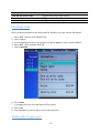
Creating an Array
1.
2.
3.
4.
5.
Navigate to the disk panel (ALT + W, then press 1)
Select each disk you wish to include in your array
Press ALT + A to open array panel
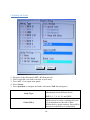
Press Create:
Press Spacebar to navigate and make selections (TAB also navigates)
Array Type
Cache Policy
Refer to RAID Level Reference Guide for
information about different levels.
RAID 0, 1, 5, 6, 10, 50, and JBOD
Write-back - Any data written to the array
will be stored as cache, resulting in better
I/O performance at the risk of data
failures due to power outages. Data will be
stored as cache before it is physically
28
written to the disk; when a power outage
occurs, any data in the cache will be lost.
Write-through - Data written to an array is
directly written onto the disk, meaning
lower write performance for higher data
availability. Without cache acting as a
buffer, write performance will be
noticeably slower but data loss due to
power outages or other failures is
significantly minimized.
Init Method
Name
Capacity
Quick Init- This option grants
immediate access to the RAID array by
skipping the initialization process, but
it will delete all data. Note: Skipping
initialization is generally not
recommended since residual data on
disks may interfere with new data in
the future.
Foreground- The array initialization
process will be set at high priority.
During this time array will be nonaccessible, but initialization
completion time will be shorter.
Background- The array initialization
process will have a lower priority.
During this time array will be
accessible, but initialization
completion time will be longer.
Keep Old Data - This option skips the
initialization process and all data on
each physical disk of the array will be
untouched.
Create array name
Designate array capacity
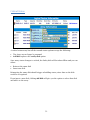
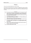
6. Press Create (ALT + E)
7. A prompt about sector size will pop up, select a sector size
8. Array will show up in the array window
29
Figure 10. Array RAID0_00 has been created.
Verifying your array
1. Navigate to the array panel (Press ALT + W, then press 2)
2. Select desired array to verify (only if you have more than 1 array. If you only have 1
array, verify will automatically start)
3. Press ALT + A to open array tab
4. Select Verify
5. You can Start/Stop the process by selecting start/stop task
Setting Boot Array
1.
2.
3.
4.
5.
Navigate to the array panel (Press ALT + W, then press 2)
Select desired array
Press ALT + A to open array tab
Press Set Boot
Window will close, reboot to confirm
Controller Tab
Provides certain controller information:
Information
Setting…
Product ID
PCI Location
IOP Model
SDRAM Size
Firmware Version
Battery Installed
Battery MB Installed
Serial Number
CPU Temperatures (Celcius)
Board Temperature (Celcius)
Controller voltage levels
Configures certain settings:
Enable audible alarm
Enable Staggered spin up
30
Spin down idle disk (minutes)
Enable automatic rebuild
Continue Rebuilding on error
INT13 support
Use single BCV entry
Stop on error
Table 3. Controller > Settings Information
Enable Audible Alarm
When a physical disk fails, the controller will emit an audible sound signaling failure.
This option enables/disables this sound.
Enable staggered spin up
Staggered Spin up is implemented for users that need to power up multiple
Harddrives. Powering on all hard drives simultaneously draws a large electrical load;
staggered spin up will power on each hard drive one at a time resulting in a stable,
lower current draw.
Enabling this setting will instruct the card to power up the hard disks sequentially (one
disk approximately every 2 seconds). Some disks do not support this feature, and it is
not recommended to enable this option if that is the case.
Spin down idle disk (minutes)
When set, physical drives will spindown a certain amount of time after disk activity
ceases.
Enable Automatic rebuild
When a physical drive fails, the controller will take the drive offline. Once you re-insert
or replace the disk, the controller will not automatically rebuild the array unless this
option is enabled.
Continue Rebuild on Error
When enabled, the rebuilding process will ignore bad disk sectors and continue
rebuilding until completion. When rebuild is finished, the data may be accessible but
data inconsistency due to ignored bad sectors may cause problems in the future. If this
option is enabled, HighPoint recommends user to check the event log for bad sectors.
Rebuild Priority
You can specify the amount of system resources you want to dedicate to rebuilding the
array. There are 5 levels of priority [Lowest, Low, Medium, High, Highest]
Provide INT13 Support
For booting purposes
Use Single BCV Entry
Single booting control vector. If you have more than one bootable HBA enable this
option.
Stop on error
If the HBA BIOS finds an error on your hard drive, it will stop the BIOS operation and
hang on BIOS screen.
31
Window Tab
The Window is the default screen you see upon entering the BIOS. The Top panel
shows all the physical drives detected, and the bottom panel shows all arrays created.
Maximize
Makes Selected Panel (Disk or Array)
fullscreen. You can press TAB to toggle
between disks and array panels.
Restore
Restores default panel configuration
1. Disk
2. Array
Selects the panel you want to work with
Refresh
Refreshes panels
Section 4: BIOS/Firmware Updates
How to Update RocketRAID BIOS/Firmware
There are two ways to update your RocketRAID BIOS/Firmware
1. Using HighPoint WebGUI Update Firmware
2. Using a bootable USB
A few reasons as to why update BIOS/Firmware
BIOS resource issue
Inefficient BIOS code may cause your
boot-up to hang during POST.
Compatibility fixes
Updating firmware may fix issues that
occur when using later hardware
Bug fixes
Bugs that are discovered post release are
fixed in subsequent updates.
Note: It is recommended to update the BIOS through HighPoint WebGUI. (See Installing
HighPoint WebGUI)
32
Having the latest BIOS ensures you have the latest firmware stability and performance
improvements. Updating the BIOS may fix boot up or system resource issues; make
sure to read the README before making any changes.
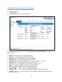
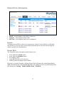
Using the WebGUI to update BIOS/Firmware
.
1. Locate the latest firmware on our webpage at www.highpoint-tech.com
2. Example firmware file will be in a zipped package with a naming convention such
as RR4522_v###_xxxx.zip (name of file subject to change)
3. Extract the contents of the file
4. Read the readme (if included) to make sure you have the correct firmware for your
HBA Note: Your HBA name and properties can be found in the WebGUI > Physical
Tab.
5. Locate the proper BIOS file (eg. 4522bios.blf, refer to the README for accuracy)
6. Log in to WebGUI (Default user: RAID pass: hpt)
7. Select your controller in the drop down menu on the top left.
8. Click the Physical tab and update firmware will be on the bottom of the page.
9. Click Choose File and browse to the BIOS file
10. Click Submit
11. Reboot
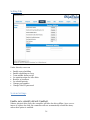
Using a Bootable USB to update BIOS/Firmware
Create a bootable USB using a utility such as Rufus. Caution: Creating a bootable USB
will erase all previous data stored on it.
1.
2.
3.
4.
Download the latest BIOS/Firmware file found at www.highpoint-tech.com
Extract the file contents onto the bootable USB
Read the README for instructions on how to flash the BIOS onto your hardware.
Reboot your computer into DOS mode by:
Setting boot priority to the bootable USB
Removing all bootable drives (OS, CD Drives) from motherboard and leaving
only the bootable USB and RocketRAID card plugged in
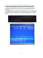
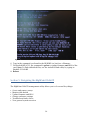
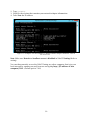
5. Once in DOS mode, you should see a command line interface
33
Figure 11. Bootable USB formatted with Rufus Utility, FreeDOS CLI (Command Line Interface)
6. Type in the command you found in the README (ex. load.exe <filename>
7. For RocketRAID 4522, the command is go.bat to update firmware and BIOS of the
card. Note: To flash individual files, use the included flash utility by typing in
flashelf 4522efi.blf
8. Reboot
Section 5: Navigating the HighPoint WebGUI
The HighPoint WebGUI management utility allows you to do several key things:
Create and remove arrays
Monitor disk health
Update firmware and BIOS
Change enclosure settings
Troubleshoot faulty drives
View general system overview
34
Tab Name
Global View
Function
View HBA (Host Bus Adapter) and
Storage Properties
Physical
View Additional Controller properties
Update BIOS/Firmware
View disk properties
Adjust selected disk behaviors
Logical
Manage and create RAID arrays
Setting
Adjust WebGUI controls settings
Event
Show WebGUI Event Log
SHI (Storage Health Inspector)
View and schedule S.M.A.R.T monitoring
Recover
Revert to previously created arrays
Logout
Logout of WebGUI
Help
Additional WebGUI documentation
Online Web Support
Installing HighPoint WebGUI
The HighPoint WebGUI is the primary link between you and your RAID array. Using the
management utilities and menus offered by the WebGUI, you will be able to access,
create, and maintain your RAID arrays.
New features are continually added to the interface; update to the latest version at
www.highpoint-tech.com.
For Windows Users:
35
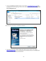
1. Locate the HighPoint WebGUI Setup on our website www.highpoint-tech.com and
download the WebGUI package. Extract the contents and double click on HighPoint
RAID Management.exe
Follow the on screen steps to install our software.
2. Log in the WebGUI by double clicking the desktop icon created or by typing
http://localhost:7402 in your preferred browsers address line (it is recommended
to use the latest version of your browser.)
36
For Linux Users:
Refer to the installation guide or README included in the driver package for the most
accurate and up to date installation steps.
1. Download the Web RAID Management (WebGUI) for Linux online at www.highpointtech.com
2. Extract the .tbz file to the desktop, and browse to the appropriate .rpm file (there
are 32 and 64-bit options).
3. Double click the .rpm file – this should open the operating systems software
installer. Enter the Administrative password when prompted and proceed with
installation.
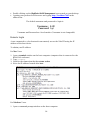
4. The package can also be installed manually, using a terminal. Log on in as “root”,
open a terminal, and browse to the location of the .rpm file. Run the following
command:
# rpm -i hptsvr-https-1.4-10.i386.rpm (or hptsvr-https-1.410.x86_64.rpm) (filename may vary)
For Debian/Ubuntu Linux distributions, you can use alien to convert the rpm
packages to a .deb package, then use "dpkg -i" command to install each package. Some
script files may be lost during the conversion process from rpm to .deb, so you may
need to make manual corrections. .
The following files will be installed/configured:
/usr/bin/hptsvr - service program
/etc/hptcfg - service config file
/etc/rc.d/init.d/hptdaemon - service control script
/usr/share/hpt/webguiroot - data files
If there is no /etc/hptcfg present, you can add it manually using by using the “echo”
command on the driver file name to /etc/hptcfg.
For example:
# echo hptiop.ko>/etc/hptcf
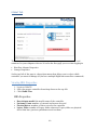
How to Login HighPoint WebGUI
You can reach the HighPoint WebGUI log in page either by:
37
Double clicking on the HighPoint RAID Management icon created on your desktop
Opening your preferred web browser and typing http://localhost:7402 in the
address bar.
The default username and password to login is
Username : RAID
Password: hpt
Username and Password are Case-Sensitive (Username is not changeable)
Remote Login
A user connected to a local network can remotely access the WebGUI using the IP
address of the host device.
To obtain your IP address
For Mac Users:
1. Open a terminal window on the host computer (computer that is connected to the
RS6422AS enclosure)
2. Type ifconfig
3. Look for the connection that has status: active
4. Write the IP address located after inet:
Figure 12. Example: en2 has active status, the IP is 192.168.1.254
For Windows Users:
1. Open a command prompt window on the host computer.
38
2. Type ipconfig
3. Look for the section that contains your network adapter information
4. Take Note the IP address
Figure 13. Example: The IPv4 address is under Ethernet adapter Ethernet 4 and is
192.168.1.143
Note: Make sure Restrict to localhost access is disabled in WebGUI Setting (Refer to
setting)
You can then remotely access the WebGUI using any other computer that is in your
local network by opening any web browser and typing http://{IP address of host
computer}:7402 (default port is 7402)
39
Global Tab
The GUI Global view provides an overview of what each HighPoint controller card
connected to your computer detects. It is also the first page you see when logging in.
Host Bus Adapter Properties
Storage Properties
On the top left of the page is a drop down menu that allows you to select which
controller you want to manage (if you have multiple HighPoint controllers connected).
Viewing HBA Properties
1. Log in to WebGUI
2. Select the proper controller from drop down on the top left
3. Click Global View
HBA Properties
Host Adapter model: the model name of the controller
Enclosure Count: number of external enclosures detected
Physical drives: number of drives seen by the controller
Legacy Disks: number of Legacy disks connected. Legacy disks are physical
drives that have previous partitions stored on them.
40
Viewing Storage Properties
1. Log in to WebGUI
2. Select the controller from drop down menu on top left
3. Click Global View
Storage Properties
Total capacity: the combined capacity of each physical disk connected to controller
Configured capacity: the amount of space used for creating arrays
Free Capacity: total amount of space unused
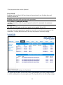
Physical Tab
The physical tab shows general and extended information about the controller you are
using. Information about the firmware, BIOS, and operating temperatures are all
located here. This information is useful for identifying what RAID controller model you
have and to make sure you have the most updated version available.
41
The physical tab contains the following information:
Controller Information
Extended Information
Update Firmware
Physical Devices Information
Controller Information:
Model Name: RocketRAID 4522 SAS Controller (for RS6422AS)
BIOS Version: v1.12 (as of 5/5/2015)
Vendor: HighPoint Technologies, Inc.
Extended Information: Gives you additional information concerning the HBA (Host
Bus Adapter) in the enclosure
IOP Model: IOP chip model number
CPU Temperature: Displays computer temperature in Celcius (°C).
Board Temperature: Displays the board temperature in Celcius (°C).
SDRAM Size: SDRAM size of the HighPoint controller card
Battery Installed: Battery Backup Unit
Firmware Version: Firmware version of the HBA
SAS address: the SAS address
Update Firmware: Allows you to update the controller BIOS through the WebGUI.
Updating BIOS/Firmware
Keeping the firmware up to date ensures that your RAID controller the latest
compatibility and performance updates. Firmware files have extension .blf.
1. Locate the latest firmware on our webpage at www.highpoint-tech.com
2. Extract the contents of the file
3. Read the README to ensure you have the correct firmware for your HBA Note:
Your HBA name and properties can be found in the WebGUI > Physical Tab.
4. Locate the proper firmware file (eg. 4520fw.blf, refer to the README for exact
name)
5. Click Choose File and browse to your firmware file
6. Click Submit
7. Reboot
42
Obtaining Physical Device Information
1. Log in to WebGUI
2. Click Physical
3. Click Devices located on the left panel
The following properties are part of the Physical Devices Information box under the
physical tab.
Model – Model number of the physical drive
Capacity – Total capacity of the physical drive
Revision – HDD device firmware revision number
Read Ahead* - (Enable/Disable) Disk read ahead.
Location – Device location (example: 1/2 states controller 1, slot 2)
Write Cache* – (Enable/Disable) the disk write cache
Max Free – space on disk that is not configured in an array
Status – (Normal, disabled, critical) status of the disk
NCQ* – (Enable/Disable) Native Command Queuing
Serial Number – serial number of the physical disk
Identify LED* – On/Off – toggle the IDENTIFY (RED) on the front panel
Unplug – Safely ejects selected disk. Other methods of disk removal will trigger
alarm if enabled.
43
* Disk properties that can be adjusted.
Read Ahead
Enabling disk read ahead will speed up read operations by pre-fetching data and
loading it into RAM.
Write Cache
Enabling write cache will speed up write operations.
NCQ (Native Command Queuing)
A setting that allows disks to queue up and reorder I/O commands for maximum
efficiency.
Identify LED
The Disk tray LED lights on the front panel can be toggled ON or OFF.
Rescan
Clicking rescan will immediately signal the controller to scan for any changes in the
connection. Clicking this button will also stop any alarm if currently ringing.
Logical Tab
The Logical tab is where you are edit, delete, and maintain your RAID configurations,
as well as, adding drives to your spare pool. The logical tab has the following settings:
44
Create Array
Spare Pool
Logical Device
Rescan
Beeper Mute
Creating an Array
To create an array:
1.
2.
3.
4.
Log into the WebGUI
Select the proper controller from the drop down on the top left
Click Logical
Click Create Array
An array is a collection of physical disks that will be seen as one virtual drive by your
Operating System (OS). The RS6422AS has a RocketRAID 4522 controller capable of
creating the following array types
45
Array Type:
JBOD – Just a Bunch of Disks
RAID 0 - Striping
RAID 1 - Mirroring
RAID 5 – Rotating Parity bit
RAID 1/0 – Striping of Mirrored Drives
RAID 5/0 – Striping of Distributed Parity
RAID 6 – Double Parity Bit
46
Each RAID level has its pros and cons based on the application you use it for (Note:
Refer to RAID level Quick Reference)
Array Name: the name that will be displayed in Logical Device Information (Default:
RAID_<level>_<array number>)
Initialization Method: Initialization of a disk sets all data bits to 0, essentially
clearing all the data on the drive. It is important to initialize disks since previous data
physically stored on the drive may interfere with new data.
Keep Old Data: This option skips the initialization process and all data on each
physical disk of the array will be untouched.
Quick Init: This option grants immediate access to the RAID array by skipping
the initialization process, but it will delete all data. Note: Skipping initialization
is generally not recommended since residual data on disks may interfere with
new data in the future.
Foreground: The array initialization process will be set at high priority. During
this time array will be non-accessible, but initialization completion time will be
shorter.
Background: The array initialization process will have a lower priority. During
this time array will be accessible, but initialization completion time will be
longer.
Note 1: Initializing takes a significant amount of time (approximately 2 hours per 1 TB).
Background and Foreground Initialization
Fully initializing the array will completely zero out the data on the disks, meaning the
disk will be completely wiped and every bit on the disk will be set to 0. Foregoing
initialization means the array will still be created, and you can still write new data onto
the array. But when your array requires rebuilding, residual data left behind may
interfere with the process.
Cache Policy (Default: Write Back)
Write Back – Any data written to the array will be stored as cache, resulting in better
I/O performance at the risk of data failures due to power outages. Data will be stored
as cache before it is physically written to the disk; when a power outage occurs, any
data in the cache will be lost.
Write Through – Data written to an array is directly written onto the disk, meaning
lower write performance for higher data availability. Without cache acting as a buffer,
write performance will be noticeably slower but data loss due to power outages or other
failures is significantly minimized.
Block Size (default: 64K)
[16K, 32K, 64K, 128K, 256K, 512K, 1024K are the supported block sizes]
47
Adjusting the block size towards your disk usage can give some performance gain.
In a typical RAID configuration, data of the virtual drive is striped (or spread across)
the physical drives. Having a smaller array block size will increase the likelihood of
accessing all physical drives when processing large I/O requests. Multiple physical
drives working in parallel increases the throughput, meaning better performance.
For smaller I/O requests (512 bytes to 4 kilobytes), it is better to have each individual
disks handle their own I/O request, improving the IOPS (I/O per second), rather than
having one tiny I/O request being handled by multiple disks.
A block size of 64k is recommended because it strikes a balance between the two I/O
usage scenarios.
Capacity (Default: Maximum)
The total amount of space you want the RAID array to take up. When creating RAID
levels, disk capacities are limited by the smallest disk.
An example of how disk capacities are limited by smallest disk.
You have 3 drives connected to the enclosure.
First drive is 6 TB, second is 4 TB, and third drive is 2 TB.
After creating a RAID level 5 using all three drives and maximum capacity
The first drive will have 4 TB, the second 2 TB, and the third drive 0 TB free capacity
The free capacity on the first and second drive can be used to create a separate
array.
You may also choose how much space each array will take. You can use the remaining
space to create another array (up to 4 arrays are supported)
Sector Size (Default: 512B)
Note: For current operating systems, this option is already implemented so changing it
in the WebGUI is not necessary.
This option will set the sector size of your virtual drive, and physical sector sizes on
your physical disks will remain the same. A sector is the smallest physical storage unit
on a disk. The default sector size is 512 B since it is the most common sector size in
disks today.
48
DV Mode
This mode is specifically designed for video applications. The default firmware cache
policy provides balanced performance for standard applications such as workstations,
file servers, and web servers. But for DV mode, a special cache firmware is implemented
specifically for large sequential writing (large I/O requests such as video files). Enabling
DV mode will maintain the performance and consistency of transferring and processing
video files.
There are several factors concerning DV mode to take note:
DV mode only available for RAID 0, 5, and 6
Only 1 RAID array you created can enable DV mode
DV mode only works when array status is normal
Margin
[5% - 25%]
When DV mode is enabled, you have the option to set the margin.
This percentage represents the amount of space the designated cache will hold before
flushing the data onto the drive. Increasing the margin % will result in more stable
performance, but decrease the maximum write performance.
Alternatively, you can change the margin anytime in Logical > Maintenance for DV
enabled array.
49
Adding Spare Disks
Spare disks are physical disks that will immediately replace critical disks in an array.
To add spare disks:
1.
2.
3.
4.
5.
Log in WebGUI
Click Logical
Click Spare Pool
Check the box for the disk you want as a spare from Available Disks
Click Add Spare
Disks added to the spare pool will show under Spare Pool and can be removed by
checking the disk checkbox from Spare Pool > Click Remove Spare
Physical drives marked as a spare will automatically be added to an array whenever
there is a disk failure. Having this feature minimizes the chances of a data loss by
reducing the time an array is in critical status.
Obtaining Logical Device Information
Logical device tab is the default page upon clicking the Logical tab of the WebGUI. This
page contains information about your RAID arrays and individual disks your system
detects.
Logical Device Information
Arrays you create and the properties associated with them will appear here.
Maintenance
Once an array has been created, you have the option maintain it.
Array Information
Clicking on the maintenance button will show you the Array information box. Different
array statuses (Normal, critical, disabled) will have different maintenance options.
50
Normal Status
A Normal Status Array has the following options:
Delete
Unplug
Verify
Change Cache Policy
Change Margin
Rename
ORLM
Delete – deletes the selected RAID array
Unplug – powers off the selected RAID array
Verify – verifies the integrity of the RAID array
Change Cache Policy – Toggles between Write through and Write back cache
Change Margin – Adjust margin when DV mode is enabled
Rename – renames the RAID array
OCE/ORLM – Online Capacity Expansion / Online RAID Level Migration
51
Critical Status
A critical status array has all the normal status options except the following:
The Array can no longer be renamed
Add disk replaces the verify disk option
Once array status changes to critical, the faulty disk will be taken offline and you can
either:
Reinsert the same disk
Insert new disk
Reinserting the same disk should trigger rebuilding status, since data on the disk
would be recognized.
If you insert a new disk, clicking add disk will give you the option to select that disk
and add it to the array.
52
Disabled Status
A disabled status array means that your RAID level does not have enough disks to
function.
Your data will be inaccessible
Rebuilding will not trigger, since RAID does not have enough parity data to rebuild
upon
Your options in Maintenance are:
Delete
Unplug
Recover
Delete – will delete the array
Unplug – will take array offline, making it safe to remove
Recover – will attempt to recover the array using the list from the recover tab
Expanding an Existing Array
Important: It is recommended to Verify/Rebuild your array before Expanding or
Migrating. Once you start an OCE/ORLM procedure, you can stop the process but it
must be resumed until completion.
To add more capacity to your current configuration follows these steps:
1. Log in WebGUI
2. Select desired controller from drop down menu on top left
3. Click Logical
4. Click Maintenance for the array you want to change
Select a different RAID level to Migrate
53
5.
6.
7.
8.
Select the same RAID level to Expand
Important: Record all the physical drives currently in array.
Click ORLM
Select the physical drives you recorded earlier and the drives you want to add
Click Submit
Upon submission, you will receive a prompt stating ORLM created successfully.
The Logical Device Information will change status to migrating.
54
Physical Device Information
Location – which controller and port the drive is located in
Model – model number of the drive connected
Capacity – total capacity of the drive
Max Free – total capacity that is not configured
Rescan
Clicking rescan will force drivers to report array status. For any disk(s) you hot plug
into the device, do not click rescan until all physical drives are detected and appear
under Logical Device Information.
Beeper Mute
The controller emits a beeping sound whenever an
Array falls into critical status
Array falls into disabled status
You unplug a disk
Your disk fails due to bad sectors
SMART sensors anticipate drive failure
If device is currently beeping, clicking Beeper Mute will mute the sound immediately.
Note: This button does not permanently mute the alarm. In order to permanently mute
the alarm, go to Setting > Enable audible alarm > Disabled.
55
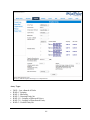
Setting Tab
Under this tab, users can
Enable auto-rebuilding
Enable rebuilding on error
Turn audible alarm on/off
Set spindown time for idle disks
Restrict to localhost
Set rebuild priority
Change port number
Change WebGUI password
System Settings
Enable auto rebuild (default: Enabled)
When a physical drive fails, the controller will take the drive offline. Once you reinsert or replace the disk, the controller will not automatically rebuild the array
unless this option is enabled.
56
Enable continue rebuilding on error (default: Enabled)
When enabled, the rebuilding process will ignore bad disk sectors and continue
rebuilding until completion. When rebuild is finished, the data may be accessible but
data inconsistency due to ignored bad sectors may cause problems in the future. If
this option is enabled, HighPoint recommends user to check the event log for bad
sectors.
Enable audible alarm (default: Enabled)
When a physical disk fails, the controller will emit an audible sound signaling failure.
This option mutes the alarm.
Set Spindown Idle Disk (minutes) (default: Disabled)
When set, physical drives will spindown a certain amount of time after disk activity
ceases. Only 10, 20, 30, 60, 120, 180, 240 minutes setting are available.
Restrict to localhost access (default: Enabled)
Remote access to the controller will be restricted when enabled, other users in your
network will be unable to remotely log in to the WebGUI.
Rebuild Priority (default: Medium)
You can specify the amount of system resources you want to dedicate to rebuilding
the array. There are 5 levels of priority [Lowest, Low, Medium, High, Highest]
Port Number (default: 7402)
The default port that the HighPoint WebGUI listens on is 7402. You may change it to
any open port.
57
Password Setting
Changing your WebGUI password
Under Password Setting type your new password and confirm it, then click submit.
Recovering your WebGUI password
If you wish to revert to the default password: hpt, delete the file hptuser.dat.
For Mac Users:
1.
2.
3.
4.
Open Terminal
Type or navigate to cd /usr/share/hpt
Type rm hptuser.dat, to remove the file
Reboot
For Windows Users:
1.
2.
3.
4.
Open file explorer
Navigate to C:/Windows/
Delete hptuser.dat
Reboot
Email Setting
The following topics are covered under email:
SMTP Setting
Adding Recipients
You can set the controller to send an email out to recipients of your choosing when
certain events (refer to Event Tab) trigger.
SMTP settings
To set up email alerts:
58
1. Check the Enable Event Notification box.
2. Enter the ISP server address name or SMTP name
3. Type in the email address of the sender (email account that is going to send the
alert)
4. Type in the account name and password of the sender
5. Type in the SMTP port (default: 25)
6. Check support SSL box if SSL is supported by your ISP (port value will change to
465).
Note: After you click ‘Change Setting’ the password box will become blank.
How to Add Recipients
You can add multiple email addresses as receivers of a notice.
1. Type the email of the recipient in the E-mail text box
2. Type the name of the recipient in the Name text box
3. Check which type(s) of events will trigger an email in the respective Event Level
check boxes
4. (Optional) Click test to confirm settings are correct by sending out a test email
5. Click add to add the recipient to recipient list
6. The added recipient will display in under Recipients
The email will send to your recipients the output recorded in the event log.
Example email message:
Figure 14. Example event log email
59
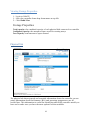
Recover Tab
Previously created arrays will be stored under this tab. Recovering an array from here
will attempt to recover a ‘disabled’ array and make it ‘normal’.
The Recover List will list all your previous and current created arrays. Each entry will
list the following properties:
Array name
RAID level
Array Capacity
Time created ( YYYY/MM/DD, HH/MM/SS, 24 hr clock format)
Location of physical drives
Model of physical drives
Important: When recovering an array it is important to note the location and model of
each physical drive because you can only recover using those exact positions and drive
model.
How to Backup your Recover List
The recover list is a record of your previously created arrays containing the model and
location information of your physical drives. Recovering from the list could help bring
a disabled array back to normal status for emergency data retrieval.
To backup your recover list:
1. Log in to WebGUI
2. Click Recover Tab
3. Click Backup to File
Note: The file will be saved as hptrec.rec
60
How to Reload your Backup Recover List
In the case that you cleared the recover list or it does not appear for any reason, you
can recover it if you saved the list beforehand.
To reload your recover list
1.
2.
3.
4.
Log in to WebGUI
Click Recover Tab
Under Update Recover List click Browse…
Locate your previously saved hptrec.rec file and select it
Note: loading a back up recover list will completely replace the current recover list.
5. Click Submit
Event Tab
In the event tab, you can see log entries associated with the HighPoint device. The
event log provides useful information when troubleshooting your set up.
In
the event tab, there are four options available:
Download – Save the log file on your computer
Clear – Clears all log entries
Prev – View previous log page
Next – View next log page
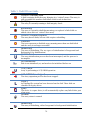
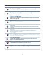
Table 4. Event Log Icon Guide
Icon
Name
Definition
Includes general
administrative tasks:
Create/delete arrays
Configuring spares
Rebuilding arrays
Configuring event
notifications
Configuring
maintenance
Information
61
Alerts issued by the Host
Adapter:
High temperatures
Sector errors
Communication
errors
Verification errors
Warning
Hardware related
problems
Hard disk failure
Broken errors
Memory failure
Error
The event view is a basic error logging tool built into the HighPoint WebGUI.
SHI (Storage Health Inspector)
S.M.A.R.T Attributes
HDD Temperature Threshold
Storage Health Inspector Scheduling
The SHI outputs information collected using SMART (Self-Monitoring Analysis and
Reporting Technology) Hard Drive Technology. The data provided on this tab helps you
to anticipate any disk failures based on a variety of monitored hard disk properties.
How to Enable SMART Monitoring
62
To access SMART attributes of an individual disk:
1.
2.
3.
4.
5.
Log in to WebGUI (default user: RAID password: hpt)
Select the proper controller using the drop down menu on the top left
Click the SHI tab
Click SMART on the desired disk
Click Enable to enable SMART monitoring
Disabling SMART monitoring
You have the option the disable SMART monitoring on each individual disk.
To disable:
1.
2.
3.
4.
Select the proper controller using the drop down menu on the top left
Click the SHI tab
Click SMART on desired disk
Click Disable
Note: Disabling SMART will prompt the Storage Health Inspector to change the disk
status to ‘Failed’. The alarm will not alert you when this setting is changed. And any
potential warnings due to S.M.A.R.T attribute technology will not
How to Change HDD Temperature Threshold
To ensure hard disk temperatures remain cool, enable SMART to monitor disk
temperatures. In SHI, you can set a threshold so that the WebGUI or controller alarm (if
enabled) can warn you when physical disks get too hot.
1.
2.
3.
4.
5.
Log in to WebGUI
Select the controller from the drop down on the top left
Click SHI
Type the desired harddisk temperature threshold (°𝐹)
Click Set
63
How to Use the Health Inspector Scheduler
The Health Inspector Scheduler (HIS) enables you to schedule disk/array checkups to
ensure disks/array are functioning optimally.
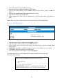
How to Create a New Verify Task
All arrays will appear under New Verify Task
1.
2.
3.
4.
5.
6.
7.
Log in to WebGUI
Select the proper controller from the top left drop down
Click SHI
Click Schedule
Select the array you want to schedule the verify task
Type the name in Task Name entry box
Choose whether you want to schedule
One time verify task on specific date (YYYY-MM-DD) at (HH:MM:SS, 24-hr clock)
Or a specific schedule you can adjust based on Daily, Weekly, or Monthly
options
8. Click Submit
9. Your entry will appear under Tasks List
64
Note: New Verify Task box only appears if you have normal status arrays. If you have a
critical array, New Rebuild Task will replace New Verify Task.
Section 6: Formatting the RAID Volumes
After creating a RAID array (see page 43), your operating system will recognize that
array as a logical disk. But it will not be accessible until it is formatted by the operating
system.
Format the volume when you have finished the following procedures:
Set up the Enclosure
Set up the RAID Controller
Installed Drivers
Created an Array
For Windows Users:
1. Use Windows Search Box and search Disk Management. (Search results may show
Create and format hard disk partitions)
2. Alternatively, Go to Control Panel
3. Under Administrative Tools, click Create and format hard disk partitions
If you just created the array, a prompt will appear after clicking disk
management asking you to initialize the disk
MBR partition table is mainly for bootable drives and has a 2 TB limit. If your PC
motherboard uses legacy BIOS, you will most likely need to use MBR for
bootable drives.
GPT partition table has no capacity limit, but cannot be bootable unless your PC
motherboard contains UEFI firmware.
65
4. Once initialized, right click the unallocated disk space for your disk
5. click New Simple Volume
6. Follow the instructions on screen to receive a drive letter
66
7. Once finished, the drive will appear in your OS with the letter you assigned
Figure 15. Disk formatted as NTFS and assigned drive letter D:
Your disk may initially appear offline to the operating system, and you may have to
bring it online:
1. In Disk Management, right click the disk you wish to bring online.
67
2. The disk status will change to Not Initialized; right click the disk again to
initialize it.
For Mac Users:
1. After creating an array using the WebGUI, you will be prompted to initialize.
2.
3.
4.
5.
6.
7.
Click Initialize (this will simply open Disk Utility)
Select your newly created array
Click Erase
Select a Format (recommended Mac OS Extended (Journaled))
Choose a name for your RAID volume
Click Erase…
68
8. The Volume will appear on your desktop
Section 7: Troubleshooting
This section provides guidelines to some problems you may encounter:
Handling Critical Arrays
Handling Disabled Arrays
69
PC hangs when card is installed.
Handling Critical Arrays
When your disk status turns critical, that means your array as a whole is still accessible,
but a disk or two is faulty (depending on your RAID level) is in danger of failing.
Common scenarios for critical
status
Unplugging disk that is part of an
array
Bad sector detected on a disk part of
the array
Unrecoverable data during rebuilding
Defective port or cable interrupts
rebuilding process
To recover from this situation,
1. Backup your existing data.
2. Identify which disk is faulty.
You can refer to the LED lights on the enclosure
Refer to the WebGUI Logical tab and Event tab.
3. Re-insert the faulty disk or replace with a new disk.
Array will rebuild automatically if your auto-rebuild setting is enabled and you
reseated the faulty disk. Note: Click Rescan if array still does not rebuild
automatically.
4. If the new disk is added and it does not automatically start rebuilding, you can
manually add the disk in maintenance.
Log in to WebGUI
Click Logical Tab
Click Maintenance > Add disk > select the appropriate disk
5. Rebuild should now start.
If rebuild does not start, click ‘Rescan’ on the left hand panel.
Note: Rebuilding an array takes on average 2 hours per 1 Terabyte of disk capacity.
The process will scan through the entire disk, even if you have very little used disk
space.
Rebuilding Stops Due to Bad Sectors
If rebuilding fails to complete due to bad disk sector errors (check in the Event Log),
there is an option to continue rebuilding on error in HighPoint WebGUI.
1. Log in to WebGUI
70
2. Click Setting tab
3. Under System Setting, change Enable Continue Rebuilding on Error to Enabled
This option will enable rebuilding to ignore bad sectors and attempt to make your data
accessible. It is important to backup immediately after backup is complete and replace
or repair the disks with bad sectors.
Critical array becomes disabled when you removed faulty disk
If this is the case, you may have removed the wrong disk. When you remove the wrong
disk from a critical array, the array status may become disabled. Data is inaccessible
for disabled arrays, follow these steps to restore the previous state.
1.
2.
3.
4.
Shut down your PC
Shut down the RS6422AS Enclosure
Place all disks back to original configuration
Boot up PC
Your array should be back to Critical status. Identify the correct disk and rebuild from
there.
Handling Disabled Arrays
If two or more disks in your array go offline due to an error or physical disconnection
your array will become disabled.
Disabled arrays are difficult to recover, so it is important to fix any critical status as
soon as possible.
To recover a disabled array, using the ‘Recover Tab’ will yield the best results. To
utilize the Recover tab, you will need to insert the exact physical drives that are listed
under the recover list.
How to recover from a Disabled Array
1. Log in to WebGUI
2. Click Maintenance for the array that is disabled
3. Click Recover
Alternatively:
1.
2.
3.
4.
5.
Log in to WebGUI
Click Maintenance for the array that is disabled
Click delete
Click Recover Tab
Select the RAID configuration you want to recover
71
6. Click Recover Array
Your PC hangs when card is installed
The moment you power on your PC the system BIOS will load and your PC will enter
POST (Power On Self Test). If you hang at this screen it may be a system resources
issue.
There are two methods to fix this problem.
1. Update your motherboard BIOS
2. Update your RAID Controller BIOS
Update your motherboard BIOS
To update your motherboard BIOS, refer to your motherboard manufacturer’s user
manual or website.
Update the RocketRAID 4522 BIOS
To update RocketRAID BIOS refer to either of these sections
Using a Bootable USB to update BIOS
Updating the BIOS through WebGUI Note: Press END to bypass the RocketRAID BIOS
splash screen so you can boot up windows and access WebGUI.
Online Array Roaming
One of the features of all HighPoint RAID controllers is online array roaming.
Information about the RAID configuration is stored on the physical drives. So if a card
fails or you wish to switch cards, the RAID configuration data can still be read by
another HighPoint card.
72
Help
Online Help
Register Product
Online Help redirects you to additional documentation concerning the HighPoint
WebGUI.
Register Product takes you to HighPoint’s web support. On this page you can create a
new customer profile where you can register your product or post an online support
ticket.
73
Table 5. WebGUI Icon Guide
Critical – missing disk
A disk is missing from the array bringing it to ‘critical’ status. The array is
still accessible but another disk failure could result in data loss.
Verifying
The array is currently running a disk integrity check.
Rebuilding
The array is currently rebuilding meaning you replaced a failed disk or
added a new disk to a ‘critical’ state array.
Critical – rebuild required
The array has all disks, but one disk requires rebuilding.
Disabled
The icon represents a disabled array, meaning more than one disk failed
and the array is no longer accessible
Initializing
The array is initializing. The two types of initialization is Foreground and
Background. (See Initialization)
Uninitialized
The array initialization process has been interrupted, and the process is
incomplete.
Not Initialized
Disk is not initialized yet, and needs to be initialized before use
OCE/ORLM
Array is performing a OCE/ORLM operation
OCE/ORLM has stopped
The array expansion process has been stopped.
Legacy
An existing file system has been detected on the disk. These disk are
classified as legacy drives.
Spare
The device is a spare drive, it will automatically replace any failed drive part
of an array.
Normal
The array status is normal
Initializing
The array is initializing, either foreground or background initialization
74
Initialization Stopped
The initialization has been stopped. Current status is uninitialized.
Critical – Inconsistency
Data in the array is inconsistent and needs to be rebuilt.
Critical – missing disk
A disk has been removed or experienced failure, and user needs to reinsert
disk or add a new disk.
Rebuilding
The array is currently rebuilding.
Verifying
The array is performing a data consistency check. Array status will show
‘verifying’.
Disabled
The array does not have enough disks to maintain the RAID level. A
disabled array is not accessible.
OCE/ORLM
Array is expanding its capacity or migrating to a different raid level. Status
will display ‘Expanding/Migrating’
OCE/ORLM stopped
The ‘Expansion/Migrating’ process has been stopped. The status will
display ‘Need Expanding/Migrating’
Critical – OCE/ORLM
A disk member is lost during the OCE/ORLM process.
Critical – OCE/ORLM - rebuild
The expanding/migrating array requires a rebuild.
75
Table 6. RAID Level Reference Guide
Type
JBOD
RAID
0
RAID
1
Description
Just a bunch of
disk
Disk Striping
Disk Mirroring
RAID
10
Disk Mirroring
followed by
stripe
RAID
5
Disk Striping
with Rotating
parity
RAID
6
Disk Striping
with dual
rotating parity
Min.
disks
1
2
2
4
3
4
Usable
space
Advantage
Disadvantage
Application
Each drive can be
accessed as a single
volume
No fault tolerance - failure
of one drive results in
complete data loss
Backup
Offers the highest
performance
No fault tolerance –
failure of one drive in the
array results in complete
data lose
Temporary file,
performance driven
application.
50%
Provides convenient
low-cost data
redundancy for smaller
systems and servers
Useable storage space is
50% of total available
capacity. Can handle 1
disk failure.
Operating system,
backup, and
transaction
database.
50%
High read performance
and medium write
performance with data
protection for up to 2drive failures
Useable storage capacity
equals total capacity of all
drives in the array minus
two
Fast database and
application servers
which need
performance and
data protection
High read performance,
and medium write
performance with data
protection with a single
drive failure
High read performance,
and medium write
performance with data
protection in case of up
to two drives failure
Not recommended for
database applications that
require frequent/heavy
write sessions. Can handle
1 disk failure.
Not recommended for
applications that require
frequent/heavy write
sessions.
Data archives, and
ideal for application
that require data
protection
100%
100%
67-94%
50-88%
76
Data archives and
ideal for application
that requires data
protection
HighPoint Recommended List of Hard Drives
HighPoint maintains a list of tested hard drives suitable for RAID applications. Since
not every hard drive in the market can be tested, this list is meant to be a general
guideline for selecting hard drives operating in a RAID environment. Regular, desktop
grade drives are highly not recommended for RAID use.
http://highpointtech.com/PDF/Compatibility_List/RocketRAID_600_2700_3600_and_4500_Series_RAID
_HBA_Hard_Drive_Compatiblity_List.pdf
Contacting Technical Support
For any help and support, submit a support ticket online at http://www.highpointtech.com/websupport/ .
You may also call us during our regular business hours:
Monday – Friday (Excluding Holidays), 9 AM to 6 PM
Phone: (408) 240-6108
77