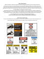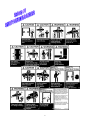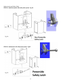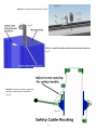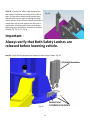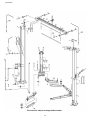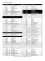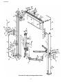
1
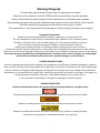
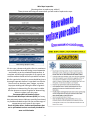
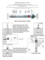
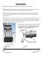
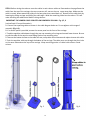
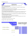
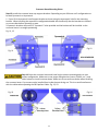
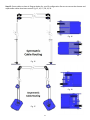
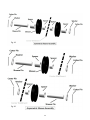
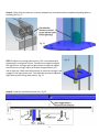
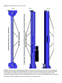
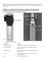
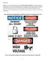
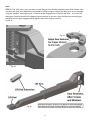
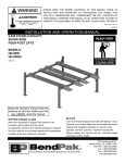
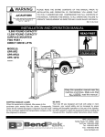
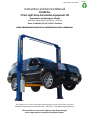
QJY245DS / QJY245DA Instruction and Service Manual 10,000 lbs. 2 Post Light Duty Automotive Equipment Lift Asymmetric and Symmetric Models Maximum Lifting Capacity 10,001 lbs. /4525 kg Meets all ANSI/ALI/ETL/CE/TUV/PCT Standards READ ENTIRE MANUAL PRIOR TO INSTALLATION AND OPERATION. This equipment must never be operated without reading this manual and the safety instructions. Safe Operating Temperature is between 40°F – 105°F (4°C - 41°C) Operating Temperature The manufacturer reserves the rights to make design changes and or improvements to product lines without notice. VERSION 8-11 OWNER’S RESPONSIBILITY DO NOT OPERATE OR REPAIR THIS EQUIPMENT WITHOUR READING THIS MANUAL. To maintain the lift and user safety, the responsibility of the owner is to read and follow these instructions: Follow all installation and operation instructions. Make sure installation conforms to all applicable Local, State, and Federal Codes, Rules, and Regulations; such as State and Federal Regulations and Electrical Codes. Inspect the lift for proper operation and function. Read and follow the safety instructions. Keep Instructions readily available for equipment operators. Make certain all equipment operators are properly trained, understand how to safely and correctly operate the unit, and are properly trained. Allow unit operation only with all parts in place and operating safely. Carefully inspect the unit on a regular basis and perform all maintenance as required. Service and maintain the unit only with authorized or approved replacement parts. Keep all instructions permanently with the unit and all decals on the unit clean and visible. Lift is Designed for Indoor Installation Only. Table of contents Page 3 3 3 3 4 5—6 7 8 8 9 10 11 12 12 – 14 13 15—16 16 16 17 17 20 17 17 18—37 38 39—42 Description Warning Paragraph Important Information Shipping Damage Claim Hazard Descriptions Warranty Operator Training and Safe Practices Safety Instructions Safety Requirements Safety Sticker Identification Warning Labels Lockout Procedure Wire Rope Inspection Concrete Foundation Specifications and Requirements Expansion Anchors Post Tension Concrete Troubleshooting Monthly Maintenance Service Calls Pre-Installation Procedure Bay Size Requirements Overall Dimensions Installation Tools Required Shipment Items Installation Procedure Post installation Procedure Parts Diagram and Specifications 2 Warning Paragraph The operation manual should be kept near the equipment at all times. Please be sure to make sure that ALL USERS read this manual before use and operation. Please read carefully the entire contents of this manual prior to installation and operation. By proceeding you agree that you fully understand and comprehend the full contents of this manual. Failure to operate this equipment as directed may cause injury or death. The manufacturer is not responsible for any damages or injury caused by improper use or neglect. Important Information: Read this manual thoroughly before installing, operating, or maintaining this lift. This lift is designed for indoor use only, and should not be installed in a pit or uneven surface. The floor on which the lift is to be installed must be 4-¼” inch minimum thickness concrete, with a minimum compressive strength of 3000 psi, and reinforced with steel bar. (Contact your building architect for information before installing on pre-stress concrete.) The lifts have specific electrical requirements as described in the Installation Instructions section of this manual. This lift has a minimum ceiling height requirement as described in the Installation Instructions section of this manual. Failure by the owner to provide the recommended shelter, mounting surface, electrical supply, and ceiling height could result in unsatisfactory lift performance, property damage, or personal injury. SHIPPING DAMAGE CLAIMS Once the equipment/product has been shipped, bill of sale passes to the Purchaser. Materials damaged in shipment claims must be made by the Purchaser against the Freight Carrier at the time of shipment arrival. Any freight damage must be noted on the freight bill before signing and reported to the freight carrier with a freight claim established. Manufacturer is not responsible for freight claims. Identify the components and check for shortages. If shortages are discovered, please contact the Distributor / Sales Representative in your area for service. It is the customers responsibility to arrange for unloading of products shipped. HAZARD DESCRIPTIONS Identify the hazard levels used in this manual with the following definitions and signal words: Immediate hazards which will result in severe liability or exposure to personal injury or death. Hazards or unsafe practices which could result in severe personal injury or death. Hazards or unsafe practices which may result in personal injury, product or property damage. Use alertness and prudence in a hazardous situation; care; wariness. 3 Warranty 2- Post Light Duty Automotive Lift Warranty Coverage 1 Year Structural Warranty (Materials and workmanship must be free of defects.) 1 Year Parts Coverage (All other assembly components and parts, such as; cables, sheaves, hydraulic components, power units, chains, valves, switches, hoses, air cylinders, fittings, misc…) No Labor The warranty does not extend to... Lifting pads and extensions. Irregularities caused by normal wear, abuse, misusage, shipping damage, improper installation, voltage or paucity of required maintenance. Damages resulting from purchaser’s neglect or failure to operate products according to instructions provided in the owner’s manual (s) and/or other accompanying instructions supplied; Normal attrition items or normally serviced items required to maintain the product in a safe operating condition; Components damaged in shipment of product. Other items not listed but may be considered general attrition items. Damage caused by rain, excessive humidity, corrosive environments or other contaminants. These warranties do not extend to any cosmetic defect not interfering with equipment functionality or any incidental, indirect, or consequential loss, damage, or expense that may result from any defect, failure, or malfunction of a product delay in performance of the warranty. Manufacturer always recommends that lift be professionally installed. Warranty applies to items only. Always follow vehicle manufacturers vehicle lifting procedures. Failure to follow vehicle manufacturers lifting procedures could cause injury and/or death. If vehicle manufacturers vehicle lifting procedures are not followed, products will not be warranted. The manufacturer reserves the right to change specifications, designs or add improvements to its product line without incurring any obligation to make such changes to products sold previously. The Manufacturer will not undertake any responsibilities for any damage caused due to incorrect installation or usage of the equipment, whether indirectly or indirectly. Manufacturer Warrants from the date it sells a product it will, at its sole option and discretion, refund the purchase price, repair, or replace such product if it contains a defect in material or workmanship. Absence of Manufacturer receipt of notification of any such defect shall constitute a waiver of all claims with regard to such product. The foregoing warranty is in lieu of all warranties, express or implied, including but not limited to the implied warranties or merchantability and fitness for a particular purpose. Manufacturer shall in no event be liable for, and customer hereby agrees to indemnify Manufacturer against all claims related to special, direct, indirect, incidental, consequential, or any other damage arising out of or related to the sale, use, or inability to use product. Other than the manufacturer’s published warranty, no warranties or conditions express or implied, written or oral, statutory or otherwise are implied. Any and all conditions and warranties implied by the Sale of Goods Act or any similar statutes are hereby expressly warranted. WARRANTY IS NOT VALID UNLESS PRODUCT IS REGISTERED. Keep a record of your lift here. Record the lift and power unit information. This information is required when calling for parts or warranty issues. Model # _____________________ Lift Serial # _____________________ Date of Mfg. _____________________ Power Unit Model # _____________________ Power Unit Date Of Mfg. _____________________ Power Unit Serial # _____________________ 4 Operator Training and Safe Practices Precautions and Safety should always be followed when Installing and Operating this lift. READ AND UNDERSTAND ALL SAFETY INSTRUCTIONS AND DECALS INCLUDED ON AND WITH THE LIFT. READ AND FOLLOW ALL SAFETY WARNING PROCEDURES IN THIS MANUAL BEFORE OPERATING LIFT. · ONLY TRAINED and AUTHORIZED PERSONNEL should operate the lift. Do not allow customers or unauthorized personnel to operate the lift or remain in the lift area. · Review regularly the safety rules and guidelines with personnel. All non-trained personnel should be kept away from work area. Never let non-trained personnel come in contact with, or operate lift. · Understand the vehicle lift operating controls before use. · Do not leave the operational controls while the lift is still in motion. · Do not stand in front of the vehicle or in the bay when vehicle is being loaded or driven into position. · Do not attempt to work on the vehicle or go near vehicle when lift is being raised or lowered. · Be aware. Watch what you are doing. Use common sense. · Stay clear of lift when raising or lowering vehicle. · Clear the area if vehicle is in danger of falling · Keep hands and feet clear. Remove hands and feet from any moving parts. Keep feet clear of lift when lowering to avoid bodily harm or any pinch points. · Do not raise or lower the vehicle unless tools, materials and people are clear. Clean up grease and oil spills immediately. When the lift is being lowered, make sure everyone is standing at least six feet away. Be sure there are no jacks, tools, equipment, left under the lift before lowering. Always lower the vehicle down when · Inspect for damaged parts. Do not use lift if any components are broken or damaged. Check all moving parts for any type of damage that may affect misalignment or operation of lift. · INSPECT THE LIFT DAILY. Do not operate if potential problems have been identified or lift malfunctions. Do not operate if lift has damaged or broken components. Never walk or work under the lift unless all safety locks are completely engaged. A daily inspection of the lift should be completed prior to its any use. Safety mechanisms, operating controls, lifting arms, ramps and any other critical parts should be inspected prior to using the lift. · ALWAYS KNOW YOUR LOAD LIMIT. Use caution so that you do not overload the lift. It is important that you know the load limit. To check the rated capacity, decals are located on one of the lift columns or contact the manufacturer. The hydraulic system on this lift is not designed to be a load holding device. Mechanical safety locks must be engaged before proceeding under the lift, with vehicle servicing, or system maintenance. Never override operating controls. This is unsafe and will void the warranty, before driving a vehicle between the columns, position all arms to insure unobstructed entry. Do not hit or run over arms as this could damage the lift and/or vehicle. · Always make sure you have proper overhead clearance · WARNING! RISK OF EXPLOSION. This equipment has internal arcing or sparking parts which should not be exposed to any flammable vapors. Do no locate this machine in a recessed area or below floor level. 5 Operator Training and Safe Practices IMPORTANT INFORMATION: · USE LIFT CORRECTLY. Use lift in the proper manner. Never use lifting adapters other than what is approved by the manufacturer. After positioning the vehicle on the lift runways, set the emergency brake, make sure the ignition is off, the doors are closed, overhead obstructions are cleared · Use all 4 arms to raise a vehicle or make sure vehicle is positioned correctly so all four corners of vehicle are stationary with wheel stops. Position all lift pads to contact vehicle manufacturers’ recommended lifting points. Raise lift slowly until all pads contact the vehicle. Check all pads for complete and secure contact with the vehicle. Check all arm restraints to insure they are engaged properly. Check that the vehicle is stable on the lift. Only after confirming these procedures, raise the lift to desired working height. · Some vehicle maintenance and repair activities may cause the vehicle to shift. Follow the manufacturer’s guidelines when performing these operations. The use of jack stands or alternate lift points may be required when completing some repairs. Special care must be used when lifting light duty trucks. Optional truck adapters may be required for each manufacturer’s recommended lifting points. Always use these lifting points. Running boards and other installed accessories may also require optional adapters. Insure vehicle is balanced when lifting light duty trucks failure to do so can cause injury and/or death. · Removal or installation of heavier parts can change the vehicle's center of gravity on the lift resulting in a critical load shift. The vehicle may then be unstable. Plan ahead for this possibility to insure continued safety and refer to the vehicle manufacturers’ service manual for recommended procedures. · Always keep the lift area free of obstructions and debris. · Never raise a vehicle with passengers inside. Before lowering a vehicle, check the lift and lift area and remove all obstructions. Before removing vehicle from the lift or lift area, position arms to the drive through position and confirm an unobstructed exit. · Use of jack stands or other load supporting devices will help in preventing load shifts. Manufacturer recommends that jack stand or other load supporting devices are used at all times for additional security. · Make sure the vehicles center of gravity is always safe before raising vehicle. Any points of contact on vehicle that are not in good contact with lifting pads or contact with lift should always be double checked. Always make sure the vehicle is secure before lifting using vehicle manufacturers’ recommended lifting points. · Do not rock the vehicle while on working on or around lift. · Do not remove any heavy component from vehicle that may cause excessive weight shift. · Verify that all safety latches are engaged and lowered on to the safety ladders before any attempt is made to work on or near vehicle. · NEVER override self-operating lift controls. · NEVER remove any safety related components parts from the lift. Does not use the lift if any safety related components parts are damaged or missing. · Pay attention when walking under a vehicle that is raised on the vehicle lift. 6 Safety Instructions: 1. Do not raise a vehicle on the lift until the installation is completed as described in this manual. 2. Technicians should be trained to use and care for the lift by familiarizing themselves with the publications listed above. The lift should never be operated by an untrained person. 3. Always position the lifting arms, ramps , adapters and accessories properly out of the way before pulling the vehicle into or out of the bay. Failure to do so could damage the vehicle and/or the lift. 4. Positioning the vehicle is very important. Only trained technicians should position the vehicle on the lift. Never allow anyone to stand in the path of the vehicle as it is being positioned. 5. Position the lifting arms, ramps , adapters and accessories to the vehicle manufacturer’s recommended pickup points. Raise the lift until contact is made with the vehicle. Make sure that the lifting arms, ramps , adapters and accessories have been properly engaged the vehicle before raising the lift to a working height. 6. Do not overload the lift. The capacity of the lift is shown on the cover of this document and on the lift’s serial number tag. 7. Keep everyone clear of the lift when the lift is in operation, the locking mechanism is disengaged, or the vehicle is in danger of falling. 8. Never override the mechanical workings or components of lift. 9. Unauthorized personnel should never be in the shop area when the lift is in use. 10. Inspect the lift daily. The lift should never be operated if components are damaged or malfunctioning. Only qualified technicians should service the lift. Replace damaged components with manufacturer’s certified parts. 11. Keep the area around the lift clean and free of debris. 12. Use additional lifting equipment or stands when removing or installing heavy vehicle components. 13. Avoid rocking of the vehicle when it is on the lift. 14. Large vehicles, such as limousines, RV’s, and long wheelbase vehicles, may not be suitable for lifting on this equipment. 15. Warning reduce the risk of personal injury, keep hair, loose clothing, fingers, and all body parts away from moving parts. 16. Warning reduce the risk of electric shock, do not use the lift when wet. The lift should not be exposed to the rain. 17. Warning reduce the risk of fire, do not operate equipment in the close proximity of open containers containing flammable liquids (example: Gasoline, flammable solvents). 18. Use the lift only as described in this manual. use only manufacturer’s recommended attachments. 19. Anyone who will be in the vicinity of the lift when it is in use should familiarize themselves with following Caution, Warning, and Safety related decals supplied with this lift and replace them if the are illegible or missing: 20. Anyone who will be in the vicinity of the lift when it is in use should read and refer to publications supplied with this lift: 21. The troubleshooting and maintenance procedures described in this manual can be done by the lift’s owner/employer. Any other procedure should only be performed by trained lift service personnel. These restricted procedures include, but are not limited to, the following: cylinder replacement, carriage and safety latch replacement, arm replacement, overhead structure replacement. 7 Safety Requirements DO NOT operate or repair this equipment without reading this manual. Failure to comply with these Instructions can result in serious bodily harm and void product warranty. Make sure you have extra help or heavy duty lifting equipment when unloading and assembling the lift. Please read the safety procedures and operating instructions in this manual before installing or operating the equipment. Keep this manual near lift at all times. Make sure all operators read this manual. Manufacturer will assume no liability for loss or damage of any kind, expressed or implied resulting from improper installation or use of this product. Do not attempt to install equipment unless you have been trained on installation procedures. Never attempt to lift components without proper lifting tools such as forklift or cranes. Stay clear of any moving parts that can fall and cause injury. Contact a Certified Installer today by dialing (1-800-000-0000 Need Number) Safety Sticker Identification Use care when identifications and markings are on lift. These identification are put in place to help with your safety and the safety of others. Always use caution when working around vehicle lift. 8 9 Lockout Procedure Purpose This procedure establishes the minimum requirements for the lockout of energy that could cause injury to personnel by the operation of lifts in need of repair or being serviced. All employees shall comply with this procedure. Responsibility The responsibility for assuring that this procedure is followed is binding upon all employees and service personnel from outside service companies (i.e., authorized installers, contactors, etc.). All employees shall be instructed in the safety significance of the lockout procedure by the facility owner/manager. Each new or transferred employee along with visiting outside service personnel shall be instructed by the owner/manager (or assigned designee) in the purpose and use of the lockout procedure. Preparation Employees authorized to perform lockout shall ensure that the appropriate energy isolating device (i.e., circuit breaker, fuse, disconnect, etc.) is identified for the lift being locked out. Other such devices for other equipment may be located in close proximity of the appropriate energy isolating device. If the identity of the device is in question, see the shop supervisor for resolution. Assure that proper authorization is received prior to performing the lockout procedure. Sequence of Lockout Procedure 1) Notify all affected employees that a lockout is being performed for servicing or maintenance and that the lift must be shut down and locked out to perform the servicing or maintenance 2) Unload the subject lift (remove vehicle). Shut it down and assure the disconnect switch is “OFF” if one is provided on the lift. 3) The authorized lockout person operates the main energy isolation device removing power to the lift being taken out of service. Stored or residual energy (such as capacitors, springs, elevated machine members, hydraulic systems, air, or etc.) must be dissipated or restrained by methods such as grounding, repositioning, blocking, bleeding down, etc. If this is a lockable device, the authorized lockout person places the assigned padlock on the device to prevent its unintentional reactivation. An appropriate tag is applied stating the person’s name, at least 3” x 6” in size, an easily noticeably color, and states not to operate device or remove tag. If this device is a non-lockable circuit breaker or fuse, replace circuit with a “dummy” device and tag it appropriately as mentioned above. 4) Ensure that the equipment is disconnected from the energy sources’ by first checking that no personnel are exposed, then verify the isolation of the equipment by operating the push button or other normal operating controls’ or by testing to make certain the equipment will not operate. . Be sure to return any switches to the “OFF” position. 5) The equipment is now locked out and ready for the required maintenance or service. Restoring Equipment to Service 1)Check the lift and the immediate area around the lift to ensure that nonessential items have been removed (clear all tools, vehicles and personnel) and that the completion of all lift components are operationally intact. 2) The authorized person can now remove the lock (or dummy circuit breaker or fuse) and tag. Activate the energy isolating device so that the lift may again be placed into operation. Rules for Using Lockout Procedure All employees are required to comply with the restrictions and limitations imposed upon them during the use of lockout. The authorized employees are required to perform the lockout in accordance with this procedure. All employees, upon observing a piece of lifting equipment which is locked out to perform servicing or maintenance shall not attempt to start, energize, or use that machine or equipment. The Lockout Procedure should be used whenever the lift is being repaired or serviced, waiting for repair when current operation could cause possible injury to personnel, or for any other situation when unintentional operation could injure personnel. No attempt shall be made to operate the lift when the energy isolating device is locked out. 10 Wire Rope Inspection (Knowing when to replace your cables!) These pictures will help you assess when you will need to replace wire rope. All wire rope, sheaves and guide rollers in continuous service should be observed during normal operation and visually as per the scheduled maintenance. A complete and thorough inspection of all ropes in use must be made as below and all rope which has been idle for a period of a month or more should be given a thorough inspection before it is put back into service. Factors such as abrasion, wear, fatigue, corrosion, improper winding and kinking are often of greater significance in determining if a wire rope is usable. Use the pictures as shown as guide for determining when to replace your wire rope. Recommended Lubrication Product: Silver Streak Wire Rope Lubricant (#199) is a heavy duty extreme pressure lubricant specially formulated to provide extended service life over a wide range of temperatures to all types of wire ropes. Check all guide rollers, sheaves and hardware that are in operational contact are visually checked for wear and lubrication 11 Concrete Foundation Specifications and Requirements Less than 10,000 lbs 2-Post Models 4 Inch Min. Thickness / 3,000 PSI (4000 PSI Recommended) FOUNDATION and ANCHORING REQUIREMENTS Before installing your new lift, check the following. Selecting Lift Location: Always use architects building plans when available. Check layout dimension against floor plan requirements making sure that adequate space is available. Floor Requirements: The lift should be located on a relatively level floor of less than 2 degrees slope. If slope is questionable, consider a survey of the site and/or the possibility of pouring a new level concrete slab. Failure to do so could cause personal injury or death. Ceiling Requirements: The area where the lift will be located should be free of overhead obstructions such as heaters, building supports, electrical lines, etc… Defective Concrete: Visually inspect the site where the lift is to be installed and check for cracked or defective concrete. If site is in question contact a local inspection agency before installing lift. DO NOT install on asphalt or other similar unstable surface. Columns are supported only by anchoring to concrete floor. Manufacturer will not be held responsible for any concrete that may not meet slope requirements and will not be responsible for any charges relating to new concrete slabs pouring or leveling or damage. IMPORTANT INFORMATION AND GENERAL NOTES FOR EXPANSION ANCHORS General Instructions for the Installing Concrete Anchors These general instructions for the installer are provided to ensure the proper selection and installation of Anchor Products and must be followed carefully. These general instructions are in addition to the specific design and installation instructions and notes provided for each particular product, all of which should be consulted prior to and during the installation Anchor Products. Use proper safety equipment. Most concrete mixes are designed to obtain the desired properties within 28 days after being cast(28-day cure). Concrete shall have compression strength of at least 3,000 PSI and a minimum thickness of 4” in order to achieve a minimum anchor embedment of 3 ¼”. NOTE: When using the standard supplied ¾” x 5 ½” anchors; if the top of the anchor exceeds 2 ¼” above the floor grade you DO NOT have enough embedment. Maintain a 6” minimum distance from any slab edge or seam. Hole to hole spacing should be a minimum 6 ½” in any direction. Hole depth should be a minimum of 4”. Do not modify Mechanical Wedge Anchor products. The performance of modified products may be substantially weakened. Manufacturer will not warrant or guarantee the performance of such modified products. Do not alter installation procedures from those set forth in this Manual. Drill holes for mechanical anchors with carbide-tipped drill bits meeting the diameter requirements of ANSI B212.15 shown in the table below. A properly-sized hole is critical to the performance of mechanical anchors. Rotary-hammer drills with light, high frequency impact are recommended for drilling holes. Do not use excessively worn bits or bits which have been incorrectly sharpened. Please note that the use of oversized holes’ is NOT permitted for anchoring lift. DO NOT USE Anchor Adhesive to fill spacing of oversize holes’. Move lift location or fill holes with Anchor Adhesive (see manufacturer for proper curing time) and Re-drill to correct Hole Specification. 12 POST TENSION CONCRETE DO NOT CUT OR DRILL THROUGH A POST TENSION CABLE. Do not disturb, bolt up, or apply load to adhesive anchors prior to the full cure of the adhesive. Metal anchors and fasteners will corrode and may lose load-carrying capacity when installed in corrosive environments or exposed to corrosive materials. There are many environments and materials which may cause corrosion including ocean salt air, fire-retardants, fumes, fertilizers, preservative-treated wood, dissimilar metals, and other corrosive elements. Finished Diameters for Rotary and Rotary Hammer Carbide Tipped Concrete Drills per ANSI B212.15 (Locate any post tension cables before you drill) Detailed Installation Instruction for Expansion Anchors. CAUTION: Anchors must be at least 6” from the edge of the slab or any seam. 1. Measure Lift Placement. (see figure ?) (Recommended use columns as template before drilling and mark holes.) 2. Keep the drill in a perpendicular line while drilling. Let the drill do the work. Do not apply excessive pressure. Lift the drill up and down occasionally to remove residue to reduce binding. 3. Drill the hole to depth equal to the length of anchor. Note: Drilling thru concrete (recommended) will allow the anchor to be driven thru the bottom of foundation if the threads are damaged or if the lift will need to be relocated. (Example A.1) 4.For better holding power blow dust from the hole. (Example A.2) 6. Repeat Steps 4 thru 5 ( Qty x 10 ). 7. Move column into place carefully. 8. Place flat washer and hex nut over threaded end of 3/4” x 5 1/2” wedge anchor, leaving approximately 1/16 inch of thread exposed carefully tap anchor (use a hammer Example A.3). Do not damage threads. Tap anchor into the concrete until nut and flat washer are against base plate. Tighten the nut, two or three turns on average concrete (28-day cure). Check each anchor bolt with torque wrench set to 100 foot pounds torque. (Example A.4) 8.1 Using the horseshoe shims provided, shim each column base as required until each column is plumb. If one column has to be elevated to match the plane of the other column, add shim plates. Torque anchors to 100 ft-lbs. Shim thickness MUST NOT exceed ½” when using the 5 ½” long anchors provided with the lift. Adjust the column extensions plumb. 8.2 Mechanical Anchors: Expansion anchors that have been set to the required installation torque in concrete will experience a reduction in pre-tension (due to torque) within several hours Re-torque the anchor to the initial installation torque is not recommended, or necessary. 8.3 For mechanical anchors that require a specific installation torque: Failure to apply the recommended installation torque can result in excessive displacement of the anchor under load or premature failure of the anchor. These anchors will lose pre-tension after setting due to pre-load relaxation. 8.4 If anchors do not tighten to 100 ft-lbs. installation torque, replace the concrete under each column base with a 4’ x 4’ x 6” thick (Recommended 4,000 PSI) 3000psi minimum concrete pad keyed under and flush with the top of existing floor. Allow concrete to cure before installing lifts and anchors (typically 28 days). See pictures below. 13 Expansion Anchor ¾” x 5-1/2” Anchor size is same as drill bit size ( .775" to .787“ ) Use a hammer drill with a Carbide tip, 3/4" diameter, solid drill bit. The bit tip diameter should be to ANSI Standard B95.12-1977. 2003 and 2006 IBC compliant high-performing medium-duty expansion anchor. Especially suited for seismic and cracked concrete applications. ICC-ES ESR-1917 supports ACI 318 design. Steps to install Expansion Anchor. 1 4 2 5 3 14 Troubleshooting The power unit does not run: - Check electrical supply breaker or fuse. - Check to see if limit switch is being contacted by a tall vehicle. - Check micro-switch and connections in motor control box. - Check voltage to the motor. - Check micro-switch and connections on the overhead switch. The power unit runs but does not raise the lift: - Check the oil level. - Check that the lowering valve is not stuck open. - Check the connections and components on the suction side of the pump. The power unit raises the lift empty but will not lift a vehicle. - Make sure the vehicle is not above the rated capacity of the lift. - Make sure the vehicle is positioned properly. - Clean the lowering valve by running the power unit for 30 seconds while holding the lowering valve open. - Check the motor voltage. Lift lowers slowly down. - Check for oil leaks. - Clean the lowering valve by running the power unit for 30 seconds while holding the lowering valve open. Repeat this procedure a few times. - Clean the check valve seat . Slow Lifting and/or oil foaming up. - Check that oil used meets the specification in the Installation Instruction section of this manual. - Tighten all suction line fittings. - Not enough oil in tank and air has been transferred into the hoses and cylinder. (Complete bleed system and replace oil.) Anchors continually work loose - If holes were drilled too large, relocate the lift per the Installation Instruction section of this manual. - Floor is not sufficient to provide the necessary resistance. Remove an area of concrete and re-pour as described in the Expansion Anchor Installation Instruction section of this manual. Lift does not raise and lower smoothly. - Reposition vehicle for a more even weight distribution. - Check the four inside corners of the two columns for roughness. Any rust or burrs must be removed with emery cloth. - Lubricate the four corners with heavy duty bearing grease. - Use a level to check the columns for vertical alignment both side to side and front to back. Shim the columns as necessary per the Installation Instruction section of this manual. - Check the oil level. - Inspect that there is no air in the hydraulic lines. Bleed the hydraulic system as described in the Installation Instruction section of this manual. 15 Troubleshooting The lift will only lower completely to 1” from the floor. -Check that the safety latches are disengaged. - Adjust cable as needed to assure that cables have not been over tightened and check that both safety latches are disengage. Safety lock are out of adjustment. - If the equalization cables are out of adjustment, the carriages are out of sync. When the lift is at full rise, one of the safety latches may not have the clearance to disengage and allow the lift to lower. Readjust cables as described in manual. At full rise the safety latch will not disengage and the lift cannot be lowered. - Check oil level. - If the equalization cables are out of adjustment, the carriages are out of sync. When the lift is at full rise, one of the safety latches may not have the clearance to disengage and allow the lift to lower. -Other issues please contact a Service Representative Power Unit will not stop running Switch is damaged. Turn off power to the lift and replace switch. Monthly Maintenance Automotive vehicle lifts an important part to the operation and profitability of your business. Make sure safety is used with this lift and other lifts in your shop is critical in preventing employee injuries and damage to customer’s vehicles. Automotive lifts should always be used safely. This will help increase the profitability, productivity and safety in your shop. Lubricate the four inside corners of the columns with heavy duty bearing grease. Check safety latch synchronization: Safety latches should click at the same time. If necessary adjust equalizing cables as described in the Installation Instruction section of this manual. Check tightness of all bolts. Check expansion anchor tightness. If the anchor bolts are loose, they should be re-torque to 100ft/lbs. Check the Hardware for tightness monthly per inspection schedules. Replace damaged, broken or wearing parts with lift manufacturer’s OEM parts or their equivalent. While lift is lowered, check the hydraulic fluid level. If necessary, add oil as described in the Installation Instruction section of this manual. Service Calls The manufacturer can provide on site service to your lift product by a qualified lift service technician. The owner is responsible for all costs and direct payment to the contractor at the time the work is completed. It is the owner’s responsibility to return any parts to the manufacturer for warranty validation. Repairs should only be completed by a qualified lift technician. 16 Pre-Installation Procedures Before beginning your installation make sure you read the installation manual and insure all instructions and safety guidelines are fully understood. Check that all component parts are accounted for. Locate the installation area, identify the center line of the bay and mark the floor. Also mark the center of bay entrance door. Connect these two points with a short chalk line in the area where lift will be located. Draw a second chalk line at 90° to locate the positions of both lift columns. (Refer to lift dimensions on this page) Keep this manual with lift at all times. DO NO INSTALL LIFT ON ASPHALT OR ANY OTHER SURFACE THAN A CONCRETE FLOOR CONFORMING TO THE MINIMUM REQUIREMENTS DETAILED IN THIS MANUAL. DO NOT INSTALL THIS LIFT ON CONCRETE WITH SEAMS OR CRACKS OR DEFECT. IF YOU HAVE QUESTION AND CONCERN CONTACT YOUR ARCHITECT. Installation Tools Required: List of items included in shipment: 16ft. Measuring Tape Chalk Line and Chalk Heavy Duty Metal Wire Cutters 3 ft Crow Bar Full set of Metric Wrenches and Ratchet Set Full set SAE Wrenches and Ratchet Set Metric and SAE Allen Key Sets Hammer Rubber Mallet Screwdrivers 2—12 ft. Step Ladders 2— 4 ft. Level 1—Rotary Hammer Drill with 3/4” diameter Masonry Drill Bit Lifting Devices Use proper lifting devices such as Cranes or a Forklift. 4” x 4” Wooden Blocks (use for unpacking) 1– Powerside Column 1– Non-Powerside Column 2—Lifting Carriages 2– Cylinders 1– Crossover Beam Assembly 1– Long Hydraulic Hose 1– Medium Hydraulic Hose 1– Short Hydraulic Hose 1—Power Unit 1—Microswitch 4—Lifting Arms 4—Drop Pins 4—Lifting Pads 4—Lift Pad Extension 1 – Dampener Pad 2– Safety latch Assemblies 2– Safety Covers 2—Boxes Hardware 12—Expansion Anchor Bolts 3/4” x 5 –1/2” 1—Installation Manual 12’ 3” Overhead Clearance Use safety protective clothing and protective wear when installing lift. 17 INSTALLATION PROCEDURE STEP 1: After unloading the lift, place it near the intended installation location. STEP 2: Remove the shipping bands and packing materials from the lift. The power unit will be unpacked from the top. Note: Be care-ful not to drop power unit on heavy end STEP 3: Open the wrapping, remove the parts and parts boxes from the packaging. Unbolt the structure from the shipping brackets. (Use proper lifting devices, cranes or a forklift to lift off of shipping brackets.) STEP 4: Slide each carriage 60-70" towards top of columns to expose base of cylinders. Open the oil port of each cylinder by unscrewing the black plastic cap. The oil port will face the backside of the column and the notch on the bottom of the cylinder will fit into the hole in the center of the base plate. (Some models do not have alignment hole.) Fig. 1 Fig. 1 STEP 5: Install the hydraulic fittings on the Cylinders inside the columns. DO NOT remove the stop plug from the nonpower side column cylinder. NOTE: Use Teflon Tape on Pipe fitting connect to cylinder port . Fig. 2 Fig. 2 Fig. 3 18 STEP 6: Before raising the columns route the cables in each column cables as illustrated on the page Route the cable from the top of the carriage, the stop connector will seat on the rear upper stop plate. Make sure the cable is routed down toward the pulley on the base plate then routed back up. Remove all the cable slack by lowering the lifting carriage and pulling the cable tight. Wind the remaining cable into the column. This will make installing the cables easier before raising columns. IMPORTANT: THE LONGER CABLE IS ROUTED ON POWERSIDE COLUMN. Fig. 4, 5, 6 (review Step# 12 more information). A. Connect the equalizing cables as shown in the cable diagram below on. Do not tighten at this stage of assembly. (Fig. # 4). B. If an access panel is provided, remove the access panel on the front of the carriage. C. Feed the equalizer cable down through the rear top mounting of carriage and around lower sheave. Be sure to pull the cable all the way thru until sitting flush on top mounting point. D. Remove the bottom sheave so the cable will seat, wrap cable around sheave and replace sheave with cable. E. Push the equalizer cable up through the bottom of the carriage. The cable must run through that front hole on the same side and out the top of the carriage. Wrap remaining portion of cable inside column. Stand column. Fig. 5 Fig. 6 Fig. 4 19 Columns STEP 7: Raise the columns and position the columns facing each other. The outside base plates meas- urements are as shown for each unit (Fig. 8) for correct measurement to your lift). Square using a chalk line and measuring from rear points on base plates (mark your positioning within 1/16”). Minimum Concrete Strength 3,000 psi 4” thick. STEP 8: Use your measurement markings made previously to center and locate lift. Once this has been accomplished use the existing holes, in the column base plate as a guide for drilling the 3/4” diameter holes into the concrete. Drill the anchor holes only for the Powerside Column, installing anchors as you go. NOTE: Drill thru concrete slab (recommended) this will allow the anchor to be driven thru the bottom of slab, if the threads are damaged or if the lift will need to be relocated. (See Foundation, Anchoring Requirements and Anchoring Tip Instructions pages 12– 14) Fig. 7 STEP 9: Using a level, check column for side-to-side plumb and front-to-back plumb. If needed, use shims provided by placing shims underneath the base plate and around the anchor bolt. This will prevent bending the column bottom plates (Shim thickness must not exceed 3/8”). Tighten 3/4” anchor bolts to 100 ft-lbs. of torque. (see page 14) (Fig 7) STEP 10: Using a tape measure, measure from back corner of the base to the opposite back corner to insure columns are square. After confirming dimensions, drill and install the anchors on the Non-Powerside Column. (Fig 8) Fig. 8 STEP 11: Level the second column as described in STEP 9. (Use the cutouts on the base plate to align at a 30 degree angle for Asymmetric configurations.) Fig Fig. 8 20 Overhead Crossover Beam Fig. 9 STEP 12: Install the overhead crossover beam. (Pages 21-25) ( Steps 12 – 18) (Fig. 9—25) STEP 12.1 : Routing Equalizing Cables A. Connect the equalizing cables as shown in the cable diagram. Do not tighten at this stage of assembly. Fig. 15, 17, 21 B. If applicable remove the access panel on the front of the carriage. C. Feed the equalizer cable down through the rear top mounting point of carriage and around lower cable sheave. Be sure to pull the cable all the way thru so it sitting flush. D. Remove the bottom sheave so the cable will seat. E. Push the equalizer cable up through the bottom of the carriage. The cable must run through that front hole on the same side and out the top of the carriage. Wrap remaining portion of cable inside column. Stand column. F. Route cable through crossover beam sheaves. Note: make sure not to cross cable over each other so cable is routed back down opposite side column. G. Fasten cable facing down on opposite side column front mounting point. H. Fasten cable end with locknut on end of cable until 1/2" of threads are showing above locknut. Pull back down through carriage until properly seated. I. Repeat steps A thru G for other cable. J. If applicable replace access panel on the front of carriage. (See pages 21-25 for complete Installation Images.) Fig. 10 21 Crossover Beam Mounting Points Step 13: Install the crossover beam top support brackets. Depending on your lift there are 2 configurations to be used Symmetric or Asymmetric. 1. If your lift is Asymmetric install support bracket as shown using the asymmetric hole for the mounting bracket . When installing the asymmetric configuration double check and verify that the brackets are located on correct sides before mounting on post. 2.Symmetric brackets will use the 3 “symmetric” holes provided and the brackets will be installed so the crossover beam in a straight positioning. Fig. 11, 12 Fig. 12 Fig. 11 Step 14: Raise the crossover beam and install on the column mounting points to your proper configuration. Make sure to use proper lifting devices (cranes, forklift, ect…) and other helpers to install crossover beam. Make sure to use extreme caution when installing the crossover beam. Cap screw must be installed from inside the post facing out. This is to avoid interference with the cables when operating the lift Equalizer Cables. Fig. 13, 14 Fig. 13 Fig. 14 22 Step 15 : Route cables as show in Diagram below for your lift configuration. Be sure to remove the sheaves and replace after cables have been routed. Fig. 15, 16, 17, 18, 19, 20 Fig. 16 Fig. 15 Fig. 18 Fig. 17 23 Fig. 19 Fig. 20 24 Step 16 : Check that the cables are correctly wrapped over all sheaves before completely adjusting cables or operating lift. Fig. 21 Fig. 21 STEP 17: Adjust the carriage cable tension. This is accomplished by tightening the carriage tie off nuts. The left post carriage nut adjusts the right column carriage, and the right column carriage nut adjusts the left column carriage. Adjust each cable to approximately 1/2” side-to-side play. Check both safety latches to insure the carriage is still engaged in the appropriate latch. The cables will need to be adjusted again when synchronizing safety latches. Fig. 22 Step 18 : Install the overhead crossover bar. Fig 23 Fig. 23 25 Fig. 22 Safety Latches and Safety Cable STEP 19 : Install non-power side safety latch system. Fig. 24 Fig. 24 STEP 20 : Install power side safety latch system. Fig 25 Fig. 25 26 Fig. 26 Step 21 : Install the Microswitch. Fig.26 Fig. 27 STEP 22 : Install the safety cable bracket on both columns. Fig. 27 Step 23 : Route the safety cable and attach to safety latch assemblies. Fig. 28 Fig. 28 27 STEP 24 : Connect the safety cable between the two latches. Check that the tension of the cable is tight. Pull the safety release handle several times and check the tension again by making sure both latches release at the same time when the handle is pulled. Note: do not over tighten this will result in malfunction of locking mechanisms. Note: before tightening check that cable is routed over all safety sheaves. Fig. 24. 25, 27, 28, 29 Fig. 29 Important : Always verify that Both Safety Latches are released before lowering vehicle. Step 25 : Install the lift pad extension brackets on each post as shown. Fig. 30 Fig. 30 28 Power Unit and Hydraulic System STEP 26 : Mount the power unit on the powerside column bracket using the four M10 x 20mm bolts and nuts. (Fig 31) A. Install the #6 SAE o-ring fitting on the power port. (Fig . 33) B. Connect the power unit hose to the power unit fitting. C. Connect the power unit hose to “T-fitting”. E. Route the long hose using the hose clamps provided. (Fig. 34, 35, 36) D. Connect the long non-powerside hose to the “T-fitting” and non-powerside port fitting. F. Connect the medium hose to the powerside fitting. G. Secure hose . Important: Make sure hose does not interfere with equalizing cable or safety cable. Fig. 31, 32, 33, 34, 35, 36 Fig. 31 Fig. 32 Install Hydraulic Fitting on Power Unit. Fig. 33 29 Step 27 : Install Hose Clamps. Fig. 34, 35, 36 Fig. 34 Fig. 35 Fig. 36 STEP 28 : Remove the vent plug from the power unit and fill the reservoir. Use a non-foaming, non-detergent hydraulic fluid Ten Weight (ISO AW32)(Example: Pure Power!® Extreme High Performance Longlife Hydraulic Oil ISO AW32is specifically formulated to provide superior anti-wear and rust inhibiting qualities, while prolonging oxidation performance for extended drain intervals.). The unit will hold approximately 4 to 5 gallons depending on tank size different amounts of fluid may be required. Fig. 38 30 STEP 29 : Connect the Electrical hookup to the power unit; 220V Single Phase. It is recommended that a 220 Volt, 30 Amp twist lock plug be installed at the power connection point. Use wire capable of supporting a 30-amp circuit. Warning: – A certified electrician must install any and all electrical wiring. Protect each circuit with time delay fuse or circuit breaker; 208v-230v single phase 60 Hz 20 amp. Verify that wiring must comply with local code. Fig. 38 Fig. 37 Description of Lift Controls Description: Purpose: Safety Release Handle Used to release safety latches when lowering vehicle. Power “ON” Button Controls electrical power to the hydraulic power unit. Push to turn-on. Lowering Handle Used to relieve hydraulic pressure when pressed to lower lifting carriages. Fill Cap Power unit fill Cap for the power unit fluid reservoir. Remove to add fluid. Tank Used to store hydraulic fluid. 31 Microswitch Step 30 : If this unit includes a safety microswitch “VERIFY AND TEST OPERATION”. Verify that micro switch is operating correctly. Operate lift and apply pressure to micro switch with a piece of non-conductive material to push down on switch. A chance of shock could occur if wiring has not been installed incorrectly. This will insure motor shuts off prior to any part of vehicle coming in contact with overhead crossbeam or preset height restrictions microswitch location. When motor shuts off while pushing “ON” button the motor will stop automatically. Lock Out Electrical Supply Before Installing Any Electrical Components To Lift. Fig. 39 Do not ever allow power supply to be connected when working on or repairing lift. 32 Arms STEP 31 : The “half moon” gear restraints on each lifting arm are already installed. Loosen Allen Screws Gear restraints will need to be adjusted once installed on lifting carriages. Position the lifting arms on the carriages using the included securing arm pins . Check for proper engagement of the arm restraints – arm lock. The safety gear restraints should fully engage the gear restraints on the arm. After checking that the safety gear restraints and arm gear engage properly, tighten Allen bolts on gear restraints. Fig 40, 41 Fig. 41 Fig. 40 Fig. 42 33 Step 32 : Install lifting carriage arm drop pins. Fig. 43 Fig. 43 STEP 33 : Install lift pads. Fig. 42 Equalizing Cables Important Notice: Equalizing Cables must be checked weekly. The tension should not be any more than 1/2" of tension slack. Failure to do this could cause an uneven lift and could cause DANGER. Equalizing cables should always be adjusted so that safety latches are in sync set on safety locks Synchronizing Safety Latches STEP 34 : Without any vehicle on the lift. Cycle the lift up and down several times to insure safety latches engage properly and all air is removed from the hydraulic system. If a bleed screw is used, bleed off excess air (see image). To lower the lift, first raise the lift to clear the safety latches, then pull down the safety release handle to lower the lift. If safety latches are out of sync, adjust the cable on the latch that engages first. Operate lift and apply pressure to cable to insure safety cable adjustment is correct. Adjust cable if necessary and secure. Remove any excess cable with wire cutters. Fig. 44 STEP 35 : Raise lift and LISTEN. You will hear the latches begin to hit and release as the lift is being raised. After 3 or 4 clicks you will hear the latches synchronizing at the same time. If the safety latches are out of synchronization you will have to readjust the equalizing cables . Operate lift and apply pressure to cable to insure cable adjustment is correct. Note: Without weight the lift will lower slowly. (Step 17) 34 Fig. 44 Step 14: Install lifting carriage arm drop pins. (Fig. 20) Equalizing Cables Important Notice: Equalizing Cables must be checked weekly. The tension should not be any more than 1/2" of tension slack. Failure to do this could cause an uneven lift and could cause DANGER. Equalizing cables should always be adjusted so that safety latches are in sync set on safety locks Synchronizing Safety Latches STEP 23: Without any vehicle on the lift. Cycle the lift up and down several times to insure safety latches engage properly and all air is removed from the hydraulic system. If a bleed screw is used, bleed off excess air (see image). To lower the lift, first raise the lift to clear the safety latches, then pull down the safety release handle to lower the lift. If safety latches are out of sync, adjust the cable on the latch that engages first. (Fig 21) STEP 24: Raise lift and LISTEN. You will hear the latches begin to hit and release as the lift is being raised. After 3 or 4 clicks you will hear the latches synchronizing at the same time. If the safety latches are out of synchronization you will have to re-adjust the equalizing cables . Operate lift and apply pressure to cable to insure cable adjustment is correct. Note: Without weight the lift will lower slowly. (Step 15) 35 Step 25: Bleed screw instructions. (Fig. 21) 36 Microswitch Step 26 : If this unit includes a safety microswitch “VERIFY AND TEST OPERATION”. Verify that micro switch is operating correctly. Operate lift and apply pressure to micro switch with a piece of non-conductive material to push down on switch. A chance of shock could occur if wiring has not been installed incorrectly. This will insure motor shuts off prior to any part of vehicle coming in contact with overhead crossbeam or preset height restrictions microswitch location. When motor shuts off while pushing “ON” button the motor will stop automatically. Lock Out Electrical Supply Before Installing Any Electrical Components To Lift. Do not ever allow power supply to be connected when working on or repairing lift. 37 Post Installation Procedure: Check Box Verify columns are properly shimmed and plumb Check that expansion anchors are tightened to 100 ft lbs. torque Roll pins / sheave pins properly attached Lifting carriage gear restraints securely fastened Electric wired by a professional technician Equalizing cables and safety latches in synchronization Safety latches functioning properly Check for hydraulic leaks Oil level full All components functioning properly All integral moving parts lubricated Check for overhead obstructions Lift arms level All hardware secure (nuts, bolts, pins) Test microswitch operation Working area clean Operation, maintenance and safety manuals in designated location This manual is subject to change without notice. 38 QJY245DA This manual is subject to change without notice. 39 Part Numbers QJY245DA This manual is subject to change without notice. 40 QJY245DS This manual is subject to change without notice. 41 Part Numbers QJY245DS This manual is subject to change without notice. 42 NOTES: _______________________________________________________________________________ ______________________________________________________________________________ ______________________________________________________________________________ ______________________________________________________________________________ ______________________________________________________________________________ ______________________________________________________________________________ ______________________________________________________________________________ ______________________________________________________________________________ ______________________________________________________________________________ ______________________________________________________________________________ ______________________________________________________________________________ ______________________________________________________________________________ ______________________________________________________________________________ ______________________________________________________________________________ ______________________________________________________________________________ 43 NOTES: _______________________________________________________________________________ ______________________________________________________________________________ ______________________________________________________________________________ ______________________________________________________________________________ ______________________________________________________________________________ ______________________________________________________________________________ ______________________________________________________________________________ ______________________________________________________________________________ ______________________________________________________________________________ ______________________________________________________________________________ ______________________________________________________________________________ ______________________________________________________________________________ ______________________________________________________________________________ ______________________________________________________________________________ ______________________________________________________________________________ 44 NOTES: _______________________________________________________________________________ ______________________________________________________________________________ ______________________________________________________________________________ ______________________________________________________________________________ ______________________________________________________________________________ ______________________________________________________________________________ ______________________________________________________________________________ ______________________________________________________________________________ ______________________________________________________________________________ ______________________________________________________________________________ ______________________________________________________________________________ ______________________________________________________________________________ ______________________________________________________________________________ ______________________________________________________________________________ ______________________________________________________________________________ 45 Torin Jacks, Inc. Ontario, CA 91761 FOR CUSTOMER SERVICE PARA EL SERVICIO PARA EL CONSUMIDOR 1-888-44-TORIN Made in China Hecho En China This manual is subject to change without notice. 46