1
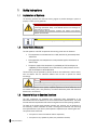
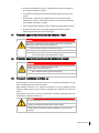
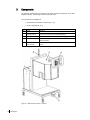
Operating Manual 360° Inspection Station Version A / Doc No.: 360°_INSPECTION_STATION_OM_EN_A_EXT.DOC Contents 1 Safety Instructions .................................................................................. 6 1.1 Explanation of Symbols....................................................................6 1.2 Basic Safety Measures .....................................................................6 1.3 Operator's Duty to Exercise Due Care .................................................6 1.4 Protection against Injuries Caused by Electrical Power .........................7 1.5 Protection against Injuries Caused by Mechanical Impact.....................7 1.6 Transport, Installation and Start-up ....................................................7 1.7 Do not open Camera Housing ...........................................................8 2 About this Manual .................................................................................. 9 2.1 General ..........................................................................................9 2.2 Scope and Audience ........................................................................9 2.3 Technical Support and Trainings........................................................9 3 Components........................................................................................ 10 4 Functions............................................................................................ 11 4.1 Scope ..........................................................................................11 4.2 Main Functions .............................................................................11 5 Start of Operation ................................................................................. 12 5.1 Electrical Checks and Working Steps................................................12 5.2 System Checks and Working Steps ..................................................12 6 Operation............................................................................................ 13 6.1 Menu structure ..............................................................................13 6.2 Structure of control window.............................................................13 7 Functions in Detail ............................................................................... 15 7.1 Starting the System ........................................................................15 7.2 Log-on to the Megapixel Print Inspection (MPI) Software ....................16 7.3 Main Menu ...................................................................................18 7.4 Format Handling ...........................................................................19 7.5 Creating new Format for Label Inspection .........................................20 7.6 Editing a Format ............................................................................29 7.6.1 Getting to the Tolerances Screen........................................................29 7.6.2 Editing the Format Tolerances ...........................................................31 7.7 Loading Format and Starting Production...........................................36 8 Production .......................................................................................... 37 8.1 Start of Production .........................................................................37 8.2 End of Production ..........................................................................37 8.3 Error Analysis................................................................................38 9 Management /Administration ................................................................. 39 10 Administration of Users and Groups ..................................................... 40 10.1 User management.......................................................................40 10.1.1 Creating a new user.......................................................................40 10.1.2 Selecting and changing current users ..............................................41 10.1.3 Saving entries ...............................................................................41 10.1.4 Deleting entries .............................................................................41 10.1.5 Description of the parameters......................................................... 41 10.2 User groups ...............................................................................41 11 Audit-Trail.........................................................................................43 11.1 Overview of the operating controls ................................................43 12 Appendix 1: Technical Data ................................................................44 12.1 Description of the Megapixel Print Inspection..................................44 12.2 Technical Data ...........................................................................44 13 Appendix 2:System restoration for Pilot and Printinspection .....................45 13.1 Backup of pilot software ..............................................................45 13.2 Backup of Megapixel PrintInspection Software ................................45 13.3 Centering Bottle in Image .............................................................49 Preface General Information These operating instructions shall add to the correct and safe application of the PCE components. Therefore, please observe the following instructions. It is necessary to read the complete operations instructions before starting up the PCE components in order to avoid false application of the systems. For your own safety, please observe the safety instructions in the operating manual. Please read the instructions carefully even if you are already used to the application and operation of PC components. This symbol displays safety instructions or the danger of injury, danger of product damage and environmental damage. < Signal > < type of danger > < consequences > < measures > The following symbol indicates important instructions and specific information: < Note > < important instructions > The Instruction Manual has to be always available for the operator, in full, where the machine is installed. Please make sure that the Instructions Manual remains in place where the machine is installed. These operating instructions do not replace installation and service by trained personnel! These operating instructions are to be treated as strictly confidential. The information given herein shall not be copied, misused or made available to third parties without PCE’s prior written consent. PCE is continuously enhancing all components.. Modifications of the scope of delivery in form, technique and configuration are subject to change. We appreciate your understanding that no claims can be made from information and illustrations of this operation manual. 1 Safety Instructions 1.1 Explanation of Symbols The following symbols and notes are warning signals of possible damage to person or property or assist you as guidelines. DANGER! This symbol can be found in the operations manual at all references concerning operational safety, if not adhered to there will be danger to body and life of persons. Always observe the instructions carefully and perform with extreme attention and wariness. Note This symbol indicates the appropriate handling of PCE-components. 1.2 Basic Safety Measures For safe operation of the PCE components the following points must be observed: The components must be mounted on a stable, mechanical, permanently fixed attachment. During operation, the components must be protected against the influence of external light. The power supply of the components is provided by 24 V DC-technique and supplied by an external power source. All necessary safety measures for this type of technique are to be adhered to. The device may only be operated by persons trained on and authorized to use the device, who are familiar with the Instruction Manual and are able to operate the device accordingly. DANGER! Lightning: Lightning causes damage to the eyes Do not look into the lightning without adequate eye protection. To ensure safe operation of the system, repeated inspections are to be carried out on all the relevant safety parts, and particularly the above-mentioned points and Instruction Manual are to be observed. 1.3 Operator's Duty to Exercise Due Care The PCE components are developed and constructed under consideration of the harmonized norms to be adhered to, as well as further technical specifications. They meet the latest technical requirements and ensure the highest level of security during operation. The safety of the system during everyday operation can, however, only be ensured if all the necessary, relevant measures are taken. Planning these measures and controlling their implementation is part of the system operator's responsibility for exercising due care. The operator must ensure that: the system is used in accordance with the stipulations, the system is only operated in perfect, fully functional condition, 6 Safety Instructions the Instructions Manual is always in a readable condition and is available, in full, where the machine is installed, only respectively qualified and authorized personnel operate and service the system, this personnel is instructed on a regular basis on all the relevant aspects concerning work safety, and that they are familiar with the Instruction Manual and the safety instructions it contains, all the system features relating to safety are carefully tested at regular intervals, the higher the safety risks are, protected against by this device, the more frequent regular inspections must be carried out. 1.4 Protection against Injuries Caused by Electrical Power DANGER! The system is operated with supply voltage! Contact with live parts can cause perilous state of shock and severe burns. Operate system with duly mounted housing only. Unplug electric supply prior to cleaning and care. In case of liquid has been spilled on the system, immediately switch off the system and unplug electric supply. 1.5 Protection against Injuries Caused by Mechanical Impact DANGER! Danger of injury by movable and rotating parts! Always adhere to the following rules: Wear adequate personal protective equipment Switch off machine prior to mechanical adjustment work. 1.6 Transport, Installation and Start-up During transport it must be ensured that the device is packed and transported as such that it is protected against moisture and impact. When installing the device in an industrial environment, this should typically be done where the adverse effects of dust, moisture, temperature and vibration are at their very lowest. Safe operation of the device can only be guaranteed if specially trained personnel have conducted the installation and start-up. DANGER! Danger of tripping and tumble accidents! Tripping- and tumble accidents lead to severe injuries! Install machine connections (cables) adequately in order to avoid tripping! Safety Instructions 7 DANGER! Rotating axes! Rotating axes! Can pull in and tear hair, clothing and jewelry. Do not operate machine with opened housing! Keep away long hair, loose clothing, jewelry etc. from machine! DANGER! Bruise: Moving Camera Ring at start-up! Camera Ring performs a reference run at start-up. When housing is opened there is a danger of bruising. When housing is opened, be careful not to allow fingers or articles of clothing to get caught into any of the moving parts. 1.7 Do not open Camera Housing Only personnel trained by PCE, is allowed to open the housing of the 360° Inspection Station. DANGER! Moving parts! Never open the housing of the 360° Inspection Station. Danger of bruising by moving parts In case of liquid has been spilled on the system, immediately switch off the system and unplug electric supply. 8 Safety Instructions 2 About this Manual 2.1 General First this operating instruction describes the system “360 Degree Inspection System”. After learning the application area, the main components, main functions and detail functions in mechanical, electrical and controlling subchapters are described. The following chapters characterize the beginning of operation and the use in production. Appendices give detailed and additional information for experts according to several chapters. 2.2 Scope and Audience This manual describes how to use and configure the 360° Inspection Station. It is intended for personnel who operate the system in order to perform 360° Inspection Station for packing lines. This includes: Operators Supervisors Administrators Engineers 2.3 Technical Support and Trainings At our website you find the latest information about our products and services. Please visit: www.pharmacontrol.de For any requests please do not hesitate to contact us via email or phone: Service line: +49 (0) 6251 85 45 – 555 / Email: [email protected] We provide extensive seminars and trainings that will help you get the most from your equipment. Our application seminars focus on industry and application issues. Individual trainings can be arranged on demand. Please contact us to request your individual training. About this Manual 9 3 Components The following pictures give an overview of the most important components of the 360° Inspection Station. The housing is made of stainless steel. The components are separated in: Mechanical and electrical components (1,3,5) Control components (2,4) Pos. Name description 1 Control cabinet Electrical cabinet consist of all electrical components and wirings 2 LED signal lamp Shows the state of the system (See chapter below) 3 Inspection housing Contains 7 cameras, illumination, and camera trigger sensor 4 Touch screen For control of the Inspection System via user interfaces of camera software and PLM 5 Hand wheel for bottle diameter This wheel has to be turned if a format with another bottle diameter is used. Figure 3-1: 360° Inspection Station - Overview 10 Components 4 Functions 4.1 Scope The intended use of the system is the pharmaceutical, medical or research area, where printed text on the side of the caps will be checked by an automated system due to quality requirements. The caps can be orientated in any direction. The system detects wrong and poor quality prints and ejects the bottle when an error is detected. 4.2 Main Functions Detect wrong / poor quality barcodes of a bottle. Reject bad samples to the reject bin. The bottles can be orientated in any direction. User Interface Main Functions The user interface allows the operator to interact with the system for: Machine controls Viewing system messages to the operator Setting up and creating new formats. Control Lamps (Signal Pillar) The control lamps have four stages: red / yellow / green / green flashing Green: System is running Red: System stopped caused by error or emergency stop Yellow flashing: Teach in mode Green flashing: Machine is ready, waiting for the camera to start Master/Slave The PLM software is the master and the MPI software is the slave. This means whenever you want to stop the production, you have to do this at first in the PLM and after this you can stop the production in the MPI software, too. Reversing this sequence leads to an error message in the PLM and production is stopped automatically. When starting the production you have to start it only in the PLM software, while the MPI software has to be in “Ready for Production” mode. Functions 11 5 Start of Operation 5.1 Electrical Checks and Working Steps 1. Switch on main switch 2. Verify the correct color of control lamps 3. Verify if the system components (cameras, user interface) are ready 5.2 System Checks and Working Steps 1. Boot the System 2. Chose the format 3. Start running the machine in production run 4. Verify the correct function of the system components 12 Start of Operation 6 Operation 6.1 Menu structure Figure 6-1 shows the menu structure of the application. After login the main menu is divided into three submenus. The format menu for loading and providing a format. The control is started in the production menu, as well as adjusting tolerances and analyzing occurred errors. The management menu provides basic settings for the system, e.g. setting up a new user or standard settings for new formats. The blue areas are optional and can be switched on if needed. The orange areas can be adopted with their options. Figure 6-1: Menu structure of the application 6.2 Structure of control window The control window of the software is divided into 3 areas. The program head shows the current format name, the logged-in user and some statistic data of production. Operation 13 The area for program messages is at the bottom edge of the program window. Current references, assistance texts, warn -und error messages can be found here. The main window in the center shows the individual program menus with the camera pictures, settings and assistance videos. On the right side there are always the respective control buttons for the possible program functions. Program head Main window Figure 6-2: Structure of control window Program messages 14 Operation 7 Functions in Detail 7.1 Starting the System To open the camera software, perform the following steps. Summarized Steps: 1. Switch on the 360° Inspection Station 2. Start the PLM and Log-on at the PLM 3. Switch to the MPI Software The steps are described below. Step 1. Action Switch on the 360° Inspection Station The PLM and the camera software are started automatically after switching on the 360° Inspection Station. Note! Regard the sequence of starting the stations, see chapter “Starting The PLM” at the PLM Manual. Step 2. Action Start the PLM and Log-on at the PLM When you have logged-in to the PLM, you are automatically logged-in to the MPI. Step 3. Action Switch to the MPI Software At the PLM screen you have to switch to the MPI screen. Use the Switch Button at the lower left corner to switch between PLM and MPI (Megapixel Print Inspection) software. The MPI software is in “Ready for Production” mode. The screen looks as follows: Functions in Detail 15 Figure 7-1: Ready for Production screen At this screen you see the last picture taken at production. From here you can get to the MAIN screen by pressing Stop. 7.2 Log-on to the Megapixel Print Inspection (MPI) Software In order to work with the MPI, it is necessary to log on with user name and password. The default account with administrator rights is: User name: 1 Password: 1 This account can be deactivated. If the above user data are not available, a help video (optional) will be displayed by pressing the “help” button to give you further assistance. Upon starting the software the user has to log on successfully with his user name and password. The log-on window will be displayed after switching-on the label check station and the automatic start of the software or by pressing Log on at the screen below (See Figure 7-2: Log-on screen. 16 Functions in Detail Figure 7-2: Log-on screen To log on perform the following steps at the screen shown in Figure 7-2: Pos. Description (1) Enter valid username with corresponding password. (2) Confirm by pressing OK. - If name or password is invalid, correct the entry. Letters can be deleted via “<-“. Functions in Detail 17 7.3 Main Menu The figure below shows the main menu where new formats can be created, system settings can be changed and error messages can be receipted. Errors are clearly indicated by a red-colored message and an error description in the footnote. Figure 7-3: Main menu The main menu is displayed… after start and successful log-on procedure. The indicated buttons can vary depending on user level (authorization). if Back has been pressed once or repeatedly in a submenu. The following table gives an overview of the functions the MAIN MENU screen provides. Detailed steps are described in the following chapters. 18 Functions in Detail Pos. Task Action (4) Create a new format Press Format in the main menu (4) Load a new format Press Format in the main menu (5) Start production Press Production (available only upon creating a valid format) (6) Conduct systems installations Press Management (requires admin-rights) (7) Exit program Press Exit 7.4 Format Handling To display the FORMAT MANAGEMENT press Format in the MAIN MENU. Note! User level (authorization) is to be respected! Visualization of the buttons depends on the user level (authorization). Figure 7-4: Main Menu > Format The following table gives an overview of the functions the FORMAT MANAGEMENT screen provides. Detailed steps are described in the following chapters. Pos. Task Description (10) Create new format A new format name can be entered. If this format has been assigned already, the button "continue" will not be displayed, the user is asked to choose a different format name instead. By clicking "continue" the set-up assistant will be displayed. (11) - List of available Formats (12) Load format: The blue-colored format in the format list "Format available" on the left side of the screen (11) will be loaded for production. In the Screenshot above the format "PagoWhiteCap-H0106" would be loaded as an example. The production screen will be displayed automatically. (13) Delete format: The format chosen in the format list will be deleted. Note: This can last for a few seconds (less than 10 seconds). (14) Copy Format: The copy feature is used to create a new format on basis of a copied format. The new format will have the same (15) Reference Image Reference image used for the format is shown. Functions in Detail 19 7.5 Creating new Format for Label Inspection In this chapter it is described how to create a new format for a bottle. The format includes the label at the side and the label on the cap of the bottle (if applicable). To create a new format for a bottle, go to the FORMAT MANAGEMENT screen (See chapter 7.4). Note! User level (authorization) to be respected! Visualization of the buttons depends on the user level (authorization). To create a new format for label inspection, perform the following steps: Summarized Steps: 1. Enter a name for the new format at the field “New product code (format) name” 2. Press New Format 3. Enter product diameter and height 4. Press next 5. Press Image 6. Select Mode: External Trigger 7. Wait for message: camera initialized successfully. Found Cameras: <6> 8. Press Machine start 9. Press next once a good image was taken. 10. Press Next (10a.) Press Barcode (if in manual mode) (10b.) Select the ROI (if in manual mode) 11. Press PLM The steps are described below. 20 Functions in Detail At the format Management screen perform the following steps: Step Action 1. Enter a name for the new format at the field “New product code (format) name” 2. Press New Format See screen: Figure 7-5: Main Menu > Format (Enter name for new Product) Once an appropriate format name has been assigned and the New Format button was clicked a progress bar will appear, as long as the cameras move down to the reference position. Functions in Detail 21 Step Action 3. Enter product diameter and height 4. Press next See screen: Figure 7-6: Typing in the diameter and height The “next” button will appear after entering diameter and height. After pressing next, the cameras will move to the correct position. 22 Functions in Detail Step Action 5. Press Image 6. Select Mode: External Trigger Figure 7-7: Options of getting a reference Image An example image must be taken that serves as a reference image. By pressing Image, the mode of the trigger can be chosen to record an image. There are three different modes: External trigger Live Image File Image Please click on the External trigger button as shown above. When pressing this button, the cameras are initialized. It takes approximately 30 to 40 seconds for camera initialization. See screen below: Functions in Detail 23 Figure 7-8: Screenshot after choosing the external trigger mode Step 7. Action Wait for message: Camera initialized successfully. Found Cameras: <6> See screen: 24 Functions in Detail Step Action 8. Press Machine start 9. Press next once a good image was taken. See screen: Figure 7-9: Triggered Image Once all the cameras are ready (Message “Camera initialized successfully. Found Cameras: <6>” appears), the ‘Machine start’ button has to be pressed, in order to start the conveyer. Press the “Machine Start” button. Images of the bottles passing through the 360° Inspection Station will now be captured as shown below in Figure 3-1. Once a suitable image is obtained, that can be used as a reference image, press next. Functions in Detail 25 Step Action 10. Press Next After taking the image there are 7 pictures, one for each camera from the side. The picture at the left bottom as shown in Figure 7-10, is the image from the top camera. Figure 7-10: Teaching in a barcode If you are in automatic teaching mode (default) keep on with Step 11. If you are in manual mode, keep on with Step 10a. 26 Functions in Detail Step Action 10a. Press Barcode 10b. Select the ROI Press the Barcode and select the ROI where the barcode may be in all images. Drag, pull and drop the red lines to configure the size of the ROI. Figure 7-11: Teaching in a barcode After choosing the area press “Stop Datainput”. The barcode will be detected automatically. The selected height of the ROI depends on the tolerances in the position of the code. Functions in Detail 27 Step Action 11. Press PLM See screen: Figure 7-12: Start Production Screen When this screen is shown you can go back to the PLM using the Switch Button and use the new format there. Note! When you have changed a format which already exists in the PLM, you can start the production and changes are taken over. You do not need to load the fields in the PLM. When you have created a new format in the MPI, you have to load the format and the fields in the PLM. Please refer to section “Line Format” in PLM Manual. Once the production is started by the PLM, the MPI software is switched to the READY FOR PRODUCTION Screen (see below). 28 Functions in Detail Figure 7-13: Ready for Production Screen (Production has been started) 7.6 Editing a Format 7.6.1 Getting to the Tolerances Screen A format can be edited manually, if the automatic teaching did not lead to the expected result. This is done at the TOLERANCES screen. To create a new format for label inspection, perform the following steps: Summarized Steps: 1. Load the Format 2. Go to MAIN screen. 3. Press Production 4. Press Tolerances 5. Press tab ‘General’ The steps are described below. Step 1 Action Load the Format as described in chapter 7.4. The format which should be edited has to be loaded previously. Functions in Detail 29 Step 2 Action Go to MAIN screen. The MAIN screen is available in two ways: a) If you are at the READY FOR PRODUCTION screen press Stop. b) If you are in any other screen press Back. Step 3 Action Press Production See screen: Figure 7-14: Main 30 Functions in Detail The PRODUCTION menu is opening (See below). Step 4 Action Press Tolerances See screen: Figure 7-15: Main > Production Step 5 7.6.2 Action Press tab ‘General’ Editing the Format Tolerances The editing options for the selected camera format are described in this chapter. Button description To increase or decrease the values of a field, put the curser into the field and use the arrow keys as described in the following table: Button Function Increase / decrease value in intervals of one. Increase / decrease value in intervals of ten. Functions in Detail 31 Increase / decrease value in intervals of hundred. Tab: General Figure 7-16: Main > Production > Tolerances (General tab) The screen shown in Figure 7-16: provides the following options: Pos. Allowed values Description Enable camera 0 or 1 0 = the program will run on a file camera; 1= it will work on the cameras Save Error images 0 to 5 0 = Do not save error image. 1 = Save error screen dump. 2 = Save error raw image. 3 = Save error raw image and screen dump. 4 = Save all raw images. 5 = Save all raw and screen dumps. No. Images to save 0 to 5 Number of images to save. Maximum value is 5 Top camera active 0 or 1 0 = switch off top camera; 1= switch on top camera. Log production result 0 or 1 0 = do not log production result in CSV file. 1= log production result in CSV file. Code process time 0 or 1 0 = Do not show datamatrix processing time in production screen . 1 = Show datamatrix processing time in production screen. Show region of interest for Code 0 or 1 0 = Do not show Region of Interest 1= Show Region of Interest Press Save to apply the changes. 32 Functions in Detail Tab: Preprocessing Figure 7-17: Main > Production > Tolerances (Preprocessing tab) The screen shown in Figure 7-17: provides the following options: Pos. Allowed values Description Rotate Image 0 or 1 0 = Rotate Image OFF; 1 Rotate Image ON Sharpen Image 0 to 4 0 = Sharpen Image OFF; 1 to 4 = Sharpen Image ON Press Save to apply the changes. Functions in Detail 33 Tab: Datamatrix Codes Figure 7-18: Main > Production > Tolerances (Datamatrix Codes tab) The screen shown in Figure 7-18: provides the following options: Pos. Allowed values Teaching mode 1 to 4 1 to 2 = Not applicable 3 = Manual Mode 4 = Automatic mode (Default) Offset width 1 to 1000 Offset for the region width. Offset height 1 to 1000 Height of the region. Readonly mode 0 or 1 If ‘Readonly mode’ is set to ‘1’, the software will return a ‘good’ signal if a barcode is found, so it is not compared with a reference barcode. Wild card active 0 or 1 0 = Wild card active 1 = Wild card inactive Polarity 0 or 1 When ‘Polarity’ is set to ‘0’ it means, that there is a black barcode on white background. When it is set to one it is the other way around. Contrast 1 of 200 Defines the smallest contrast for the barcode with respect to background. Timeout 30 to 1000 The maximum time (in ms) the finding of a barcode can last. Press Save to apply the changes. 34 Functions in Detail Description Tab: SPS Figure 7-19: Main > Production > Tolerances (SPS tab) The screen shown in Figure 7-19: provides the following options: Pos. Allowed values Description Hardware good signal 1 Do not change this value! Camera movement 1 Do not change this value! Fixed focus diameter 85 Do not change this value! Fixed focus distance 78 Do not change this value! Movement position 78 Do not change this value! Press Save to apply the changes. Functions in Detail 35 Button: Print Inspection At the General tab you see the button “Print Inspection”, click it to get to the screen where you can change the barcode fields. Figure 7-20: Main > Production > Tolerances (General tab) The production window can be achieved by pressing Back. 7.7 Loading Format and Starting Production After starting the program, the last used format will be loaded and production can be started (See chapter 8.1). 36 Functions in Detail 8 Production The menu picture appears after successful teach-in of a format or pressing the Production button. Operating instructions: Figure 8-1: Starting the Production 8.1 Start of Production The screen shown in Figure 8-1 provides the following options: 8.2 Pos. Description (24) Start the production modus of the software with "start" button End of Production The screen shown in Figure 8-1 provides the following options: Pos. Description (25) Error review: Error pictures can be visually inspected on this screen (26) Tolerances: Tolerances of the print controls can be modified with the correct user level if needed. (27) Help: Provides a context sensitive help that leads you to the corresponding chapters of the manual. (28) Back: The Back button leads back to the previous screen. Production 37 8.3 Error Analysis The error analysis of the production menu shows the pictures of the latest false readings. These pictures can be exported for further archiving. The export path for the pictures is <C:\temp>, but can be configured as desired. With “Reset Counter” good and bad product statistics are set to zero and the existing pictures indicating defects are deleted. Figure 8-2: error images 38 Production 9 Management /Administration The management menu covers all system settings. In this menu, a wide variety of parameters affecting the configuration and operation of the Megapixel Printinspection software can be set. This menu is generally accessible to users who have administrator rights. The management menu comprises the following areas: User management Audit-Trail Standard tolerances Advanced camera parameters Software setting Audit-PDF The individual areas are organized in tab form and can be selected by touching the tab name in the top of the window. Select “Back” if you want to exit the management area. CAUTION! The settings in the management area directly affect the function and precision of the various inspections and of the software in general. An improper configuration can have serious consequences (malfunction, non-recognition of defective products, and high rate of false exclusions). The changing of these parameters must be restricted to technicians with the appropriate professional training and knowledge! Note! Note client-specific configuration! Depending on the configuration, the display and the available operating controls may differ from the illustrated screenshots. Management /Administration 39 10 Administration of Users and Groups 10.1 User management All current users are managed in user management. New users can be created and global settings regarding access to the software can be adjusted. Figure 10-1: creating a new user The screen shown in Figure 10-1: provides the following options: Pos. Description (41) User list: Listing of all current users. (42) User details: entry of user name and password, and where appropriate, the first and last name. (43) Active: Setting for activating or deactivating a user. (43) User Rights: Setting up the user group and hence the rights in the software. (43) Additional rights: For specifying whether users may end programs, shut down the system, or change tolerances. (44) Password expiration (optional): Password validity period in days. (44) Automatic logout (optional): Time until automatic logout in minutes. (44) Password configuration: Activating/deactivating whether the password must be alphanumeric or case sensitive. 10.1.1 Creating a new user Input a user name that is unique and not already in use. [optional] Input first and last name. These data will be displayed in the software header after successfully logging 40 Administration of Users and Groups on. Input password. This password must comply with the specifications (minimum password length, alphanumeric password). If these conditions are fulfilled, the password must then be input a second time in the field that appears. Select user group (operator, administrator, line viewer) Select additional rights (authorization to end the program, authorization to shut down the system, authorization to change tolerances) Save changes with “Save”. After saving, the new user will appear in the user list. 10.1.2 Selecting and changing current users 1. Touch and keep your finger on the desired user name in the user list until the user is selected and the user data become visible in the corresponding fields. 2. Make the desired changes. 3. Save changes with “Save”. 10.1.3 Saving entries Choose “Save” to save your changes. 10.1.4 Deleting entries Choose “Delete” to delete the entries and reset all input fields. 10.1.5 Description of the parameters Parameter Description Active The user has access if there is a checkmark here, otherwise this user is barred. Authorization to end the program If activated, the button for ending the program is available in the main menu. Authorization to shut down the system If activated, the button for shutting down the PC system is available in the main menu. Authorization to change tolerances If activated, the user has access to the format-specific tolerances. (<Tolerances> button available in the main menu) Password expiration (optional) Specifies how many days a user has to renew his/her password (-1 = inactive) Automatic logout (optional) Specifies the number of minutes after which a user will be automatically logged off. Alphanumeric password (optional) If activated, the password must contain letters as well as numbers. Case-sensitive password (optional) If activated, the password is case-sensitive. 10.2 User groups Administration of Users and Groups 41 The following table shows a listing of available program functions, depending on the group affiliation of the logged-in operator. Individual user rights can also be set individually (see the description of the parameters). User group Functions Load format Create format Delete format Start production Error analysis Change format tolerances Management User management Audit-Trail Standard tolerances Standard parameter Software settings 42 Administration of Users and Groups Administrator Line Operator Line Viewer X X X X X X X X X X X No access No access X No access X configurable configurable X X X X X X No access No access No access No access No access No access No access No access No access No access No access No access 11 Audit-Trail In the window “Audit-Trail” log files can be displayed and evaluated. This system log contains all user actions, e.g. log-in procedure, start/stop of the production or setting changes. In addition it is possible to view the batch data in this area. 11.1 Overview of the operating controls Figure 11-1: example of the operating controls The screen shown in Figure 11-1 provides the following options: Pos. Description (45) Audit- Trail file: listing of all existing Audit-Trail and batch reports. (46) Print: choose “Print” to print out the selected file. (47) “<” or “>”: choose this button to select the previous or the next file. Audit-Trail 43 12 Appendix 1: Technical Data 12.1 Description of the Megapixel Print Inspection The operating instructions available describe the procedure of using the PCE Megapixel Print Inspection system. At the PCE Megapixel Print Inspection system the PCE control system is operated via the user terminal (15“touch screen TFT monitor). Operations are executed by touching the display functions. Verification of the PCE camera system of all products ensures that only correct and therefore clearly identified products shall leave the machine. The PCE Megapixel Print Inspection system consists of the following components: Illumination unit 7 Megapixel cameras Computer with respective interfaces 15“ touch screen TFT monitor as operations terminal The following items are located in the integrated switchboard: Power supply for all connected cameras and PCE-machines Fuses, optocoupler, for the complete galvanic disconnection of all machine inputs and outputs as well as terminal strip and trigger plate. Computer 12.2 Technical Data 44 User terminal Optimal Resolution: 1024 x 768; Monitor input voltage, current: 110/220V AC 60/50Hz PCE Mega Pixel-Camera 7 pieces of 2-Megapixelkamera, CCD, meeting the GMPrequirements; 12 V DC , power consumption is model specific power input max. 2A Switchboard protection class IP54 / CE; input 110/220V AC 60/50Hz Illumination unit 24V High power white light LED panel Appendix 1: Technical Data 13 Appendix 2:System restoration for Pilot and Printinspection 13.1 Backup of pilot software The camera backup can be started directly from the backup menu in the pilot program. This backup contains as a zip file. It can be found in the folder c:\pce\pilot\database. The whole database of the program has to be copied to a separate device. Therefore copy the folder C:\pce\pilot and c:\pce\db to this device. For further information please consult the pilot user manual. 13.2 Backup of Megapixel PrintInspection Software Figure 13-1: For creating a backup of the PrintInspection, the monitor has to be changed. Therefore click on the icon called “MPI” (see 0). Appendix 2:System restoration for Pilot and Printinspection 45 Figure 13-2: After changing to the PrintInspection, the software has to be stopped. Therefore click on button “Stop” (see 1). Figure 13-3: When the software has stopped, the screen should look like the picture above. Click on the “Back” button (see 2) to go to the main menu. 46 Appendix 2:System restoration for Pilot and Printinspection Figure 13-4: At the main menu click at the “Management” button (see 3). Figure 13-5: Click on “Additional Options” (see 4) in this menu and go to “Create SW Backup” (see 5). Appendix 2:System restoration for Pilot and Printinspection 47 Figure 13-6: Connect to an usb drive and search for this folder in the window that appeared after clicking on “Create SW Backup” (see 6). After selecting the right folder click “OK”. Figure 13-7: A window should appear that tells you, how long the copy would last (see 7). The folder is saved with a timestamp that contains date and time. This folder has to be copied to the server. For example: The copy has started at 16:37 on 22nd august 2012, the folder is named as: 48 Appendix 2:System restoration for Pilot and Printinspection 2012_08_22_(16;37)_BackupPrintinspection. If the program has to be restored, take the backup folder, rename it to Printinspection, copy it to C: and overwrite the current version 13.3 Centering Bottle in Image Figure 13-8: Triggered Image The vertical green lines at the center of each image are used as a reference line to adjust your trigger sensor so that center of the bottle coincides with this line in all the 6 images. Appendix 2:System restoration for Pilot and Printinspection 49 Author: Pharmacontrol Electronic GmbH No part of this documentation shall be re-produced, transmitted, assigned, recorded in a data processing system or translated into another language in any form without prior written consent.