1
Order No. PHAAM1201104C2
Indoor Unit
WH-SHF09D3E5
WH-SHF12D6E5
Outdoor Unit
WH-UH09DE5
WH-UH12DE5
WARNING
This service information is designed for experienced repair technicians only and is not designed for use by the general public.
It does not contain warnings or cautions to advise non-technical individuals of potential dangers in attempting to service a product.
Products powered by electricity should be serviced or repaired only by experienced professional technicians. Any attempt to
service or repair the product or products dealt with in this service information by anyone else could result in serious injury or death.
PRECAUTION OF LOW TEMPERATURE
In order to avoid frostbite, be assured of no refrigerant leakage during the installation or repairing of refrigerant circuit.
© Panasonic Appliances Air-Conditioning (M) Sdn. Bhd. 2012.
Unauthorized copying and distribution is a violation of law.
TABLE OF CONTENTS
PAGE
PAGE
14.1
14.2
14.3
14.4
14.5
14.6
3. Features...............................................................9
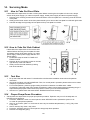
How to Take Out Front Plate ...................... 58
How to Take Out Side Cabinet ................... 58
Test Run ..................................................... 58
Proper Pump Down Procedure................... 58
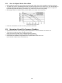
How to Adjust Water Flow Rate.................. 59
Expansion Vessel Pre Pressure
Checking ..................................................... 59
4. Location of Controls and Components..........10
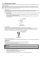
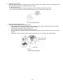
15. Maintenance Guide.......................................... 60
1. Safety Precautions .............................................3
2. Specifications .....................................................5
2.1
2.2
4.1
4.2
WH-SHF09D3E5 WH-UH09DE5 ..................5
WH-SHF12D6E5 WH-UH12DE5 ..................7
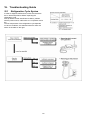
16. Troubleshooting Guide................................... 62
Indoor Unit ...................................................10
Outdoor Unit.................................................15
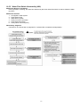
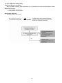
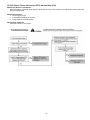
16.1 Refrigeration Cycle System ........................ 62
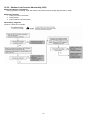
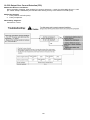
16.2 Relationship between the Condition of the
Air-to-Water Heatpump Indoor and Outdoor
Units and Pressure and Electric Current .... 63
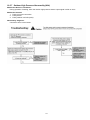
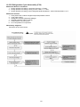
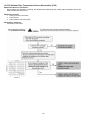
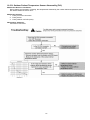
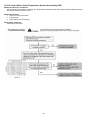
16.3 Breakdown Self Diagnosis Function ........... 64
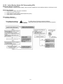
16.4 Error Codes Table....................................... 65
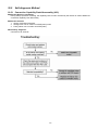
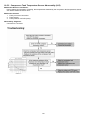
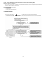
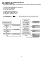
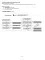
16.5 Self-diagnosis Method ................................ 67
5. Dimensions .......................................................16
5.1
5.2
Indoor Unit ...................................................16
Outdoor Unit.................................................17
6. Refrigeration and Water Cycle Diagram ........18
7. Block Diagram ..................................................20
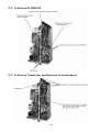
17. Disassembly and Assembly Instructions ... 101
8. Wiring Connection Diagram ............................21
8.1
8.2
17.1
17.2
17.3
17.4
17.5
17.6
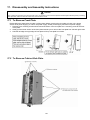
To Remove Front Plate............................. 101
To Remove Cabinet Side Plate ................ 101
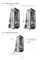
To Remove Pressure Gauge .................... 102
To Remove Control Panel ........................ 102
To Remove RCCB/ELCB.......................... 103
To Remove Transformer and Electronic
Controller Board........................................ 103
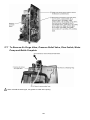
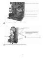
17.7 To Remove Air Purge Valve,
Pressure Relief Valve, Flow Switch,
Water Pump and Bottle Complete ............ 104
Indoor Unit ...................................................21
Outdoor Unit.................................................23
9. Electronic Circuit Diagram ..............................24
9.1
9.2
Indoor Unit ...................................................24
Outdoor Unit.................................................26
10. Printed Circuit Board .......................................27
10.1 Indoor Unit ...................................................27
10.2 Outdoor Unit.................................................29
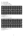
18. Technical Data ............................................... 106
11. Installation Instruction.....................................31
11.1
11.2
11.3
11.4
18.1 Heating Capacity Table............................. 106
18.2 Heating Capacity at Different Piping
Length ....................................................... 107
18.3 Hydraulic Pump Performance................... 107
18.4 Usage Limitation ....................................... 107
Select the Best Location ..............................31
Indoor/Outdoor Unit Installation Diagram ....31
Indoor Unit ...................................................32
Outdoor Unit.................................................37
12. Operation and Control .....................................40
19. Exploded View and Replacement Parts
List .................................................................. 108
12.1 Basic Function .............................................40
12.2 Water Pump .................................................46
12.3 Pump Down Operation ................................47
12.4 Flow Switch..................................................47
12.5 Force Heater Mode Operation .....................47
12.6 Indoor Unit Safety ........................................48
12.7 Auto Restart Control ....................................48
12.8 Indication Panel ...........................................48
12.9 Indoor Back-Up Heater Control ...................49
12.10 Tank Booster Heater Control .......................50
12.11 Three Way Valve Control.............................50
12.12 Sterillization Mode........................................50
12.13 Quiet Operation............................................51
12.14 Solar Operation (Optional)...........................51
12.15 External Room Thermostat Control
(Optional) .....................................................54
19.1 WH-SHF09D3E5 WH-SHF12D6E5 ......... 108
19.2 WH-UH09DE5 WH-UH12DE5 ................. 110
13. Protection Control............................................55
13.1 Protection Control for All Operations ...........55
13.2 Protection Control for Heating Operation ....57
14. Servicing Mode .................................................58
2
1. Safety Precautions
Read the following “SAFETY PRECAUTIONS” carefully before perform any servicing.
Electrical work must be installed or serviced by a licensed electrician. Be sure to use the correct rating and main
circuit for the model installed.
The caution items stated here must be followed because these important contents are related to safety. The
meaning of each indication used is as below. Incorrect installation or servicing due to ignoring of the instruction
will cause harm or damage, and the seriousness is classified by the following indications.
WARNING
This indication shows the possibility of causing death or serious injury.
CAUTION
This indication shows the possibility of causing injury or damage to properties.
The items to be followed are classified by the symbols:
This symbol denotes item that is PROHIBITED from doing.
Carry out test run to confirm that no abnormality occurs after the servicing. Then, explain to user the operation,
care and maintenance as stated in instructions. Please remind the customer to keep the operating instructions for
future reference.
WARNING
1. Do not modify the machine, part or material during repairing service.
2. If wiring unit is supplied as repairing part, do not repair or connect the wire even partial wire break. Exchange the whole wiring unit.
3. Do not wrench the fasten terminal. Pull it out or insert it straightly.
4. Do not install outdoor unit near handrail of veranda. When installing outdoor unit at veranda of high rise building, child may climb up to
outdoor unit and cross over the handrail and causing accident.
5. Do not use unspecified cord, modified cord, joint cord or extension cord for power supply cord. Do not share the single outlet with other
electrical appliances. Poor contact, poor insulation or over current will cause electrical shock or fire.
6. Do not tie up the power supply cord into a bundle by band. Abnormal temperature rise on power supply cord may happen.
7. Do not insert your fingers or other objects into the unit, high speed rotating fan may cause injury.
8. Do not sit or step on the unit, you may fall down accidentally.
9. Keep plastic bag (packaging material) away from small children, it may cling to nose and mouth and prevent breathing.
10. Do not use pipe wrench to install refrigerant piping. It might deform the piping and cause the unit to malfunction.
11. Do not purchase unauthorized electrical parts for installation, service, maintenance and etc.. They might cause electrical shock or fire.
12. Do not modify the wiring of indoor/outdoor unit for installation of other components (i.e. heater, etc). Overloaded wiring or wire
connection points may cause electrical shock or fire.
13. Do not add or replace refrigerant other than specified type. It may cause product damage, burst and injury etc.
14. For electrical work, follow local wiring standard, regulation and this installation instruction. An independent circuit and single outlet must be
used. If electrical circuit capacity is not enough or defect found in electrical work, it will cause electrical shock or fire.
15. For water circuit installation work, follow to relevant European and national regulations (including EN61770) and local plumbing and building
regulation codes.
16. Engage dealer or specialist for installation or servicing. If the installation or servicing done by the user is defective, it will cause water leakage,
electrical shock or fire.
17. This is a R407C model, when connecting the piping, do not use any existing (R22) pipes and flare nuts. Using such same may cause
abnormally high pressure in the refrigeration cycle (piping), and possibly result in explosion and injury. Use only R407C refrigerant.
Thickness or copper pipes used with R407C must be 0.8 mm or more. Never use copper pipes thinner than 0.8 mm.
It is desirable that the amount of residual oil is less than 40 mg/10 m.
18. When install or relocate Air to Water Heatpump indoor/outdoor unit, do not let any substance other than the specified refrigerant, eg. air etc
mix into refrigerant cycle (piping). Mixing of air etc. will cause abnormal high pressure in refrigeration cycle and result in explosion, injury etc.
3
19. Install according to this installation instructions strictly. If installation is defective, it will cause water leakage, electrical shock or fire.
20. Install at a strong and firm location which is able to withstand the set’s weight. If the strength is not enough or installation is not properly done,
the set will drop and cause injury.
21. Do not use joint cable for indoor/outdoor connection cable. Use specified indoor/outdoor connection cable, refer to instruction CONNECT
THE CABLE TO THE INDOOR UNIT and connect tightly for indoor/outdoor connection. Clamp the cable so that no external force will be acted
on the terminal. If connection or fixing is not perfect, it will cause heat up or fi re at the connection.
22. This equipment is strongly recommended to be installed with Residual Current Device (RCD) on-site according to the respective national
wiring rules or country-specific safety measures in terms of residual current.
23. During installation, install the refrigerant piping properly before run the compressor. Operation of compressor without fixing refrigeration piping
and valves at opened condition will cause suck-in of air, abnormal high pressure in refrigeration cycle and result in explosion, injury etc.
24. During pump down operation, stop the compressor before remove the refrigeration piping. Removal of refrigerant piping while compressor is
operating and valves are opened will cause suck-in of air, abnormal high pressure in refrigerant cycle and result in explosion, injury etc.
25. Tighten the flare nut with torque wrench according to specified method. If the flare nut is over tightened, after a long period, the flare may
break and cause refrigerant gas leakage.
26. After completion of installation, confirm there is no leakage of refrigerant gas. It may generate toxic gas when the refrigerant contacts with fire.
27. Ventilate the room if there is refrigerant gas leakage during operation. Extinguish all fire sources if present. It may cause toxic gas when the
refrigerant contacts with fire.
28. Only use the supplied or specified installation or servicing parts, else, it may cause unit vibrate loose, water leakage, electrical shock or fire.
29. The unit is only for use in a closed water system. Utilization in an open water circuit may lead to excessive corrosion of water piping and risk of
incubating bacteria colonies, particularly Legionella, in water.
30. If there is any doubt about the installation procedure or operation, always contact the authorized dealer for advice and information.
31. Select a location where in case of water leakage, the leakage will not cause damage to other properties.
32. When installing electrical equipment at wooden building of metal lath or wire lath, in accordance with electrical facility standard, no electrical
contact between equipment and building is allowed. Insulator must be installed in between.
33. Work done to the indoor/outdoor unit after remove the front plate cover that secured by screws, must be carried out under the supervision of
authorized dealer and licensed installation contractor.
34. This equipment must be properly earthed. Earth line must not be connected to gas pipe, water pipe, earth of lightning rod and telephone.
Otherwise, it may cause electrical shock in case equipment breakdown or insulation breakdown.
CAUTION
1. Do not install the air-to-water heatpump indoor unit and outdoor unit at place where leakage of flammable gas may occur. In case gas
leaks and accumulates at surrounding of the unit, it may cause fire.
2. Do not release refrigerant.
Do not release refrigerant during piping work for installation, re-installation and during repairing a refrigeration parts. Take care of the
liquid refrigerant, it may cause frostbite.
3. Do not install this appliance in a laundry room or other high humidity location. This condition will cause rust and damage to the unit.
4. Make sure the insulation of power supply cord does not contact hot part (i.e. refrigerant piping, water piping) to prevent from insulation
failure (melt).
5. Do not touch the sharp aluminium fin, sharp parts may cause injury.
6. Do not apply excessive force to water pipes that may damage the pipes. If water leakage occur, it will cause flooding and damage to
other properties.
7. Carry out drainage piping as mentioned in installation instructions. If drainage is not perfect, water may enter the room and damage the
furniture.
8. Select an installation location which is easy for maintenance.
9. Power supply connection to indoor unit.
Power supply point should be in easily accessible place for power disconnection in case of emergency.
Must follow local national wiring standard, regulation and this installation instruction.
Strongly recommended to make permanent connection to a circuit breaker. It must be a double pole switch with a minimum 3.0 mm gap.
- Use approved 30A circuit breaker for power supply 1
- Use approved 30A circuit breaker for power supply 2
- Use approved 15A/16A circuit breaker for power supply 3 (Not applicable for SHF09D3E5)
10. Ensure the correct polarity is maintained throughout all wiring. Otherwise, it will cause electrical shock or fire.
11. After installation, check the water leakage condition in connection area during test run. If leakage occur, it will cause damage to other
properties
12. Installation work.
It may need two or more people to carry out the installation work. The weight of indoor/outdoor unit might cause injury if carried by one person.
4
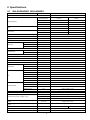
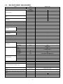
2. Specifications
2.1
WH-SHF09D3E5 WH-UH09DE5
Item
Unit
Outdoor Unit
Performance Test Condition
EN14511
Condition
(Ambient/Water)
kW
Heating Capacity
A7W35
A2W35
9.00
9.00
BTU/h
30700
30700
kcal/h
7740
7740
W/W
4.55
3.40
kcal/hW
3.91
2.92
dB (A)
49
-
Power Level dB
66
COP
Noise Level
3
Air Flow
3
m /min (ft /min)
Refrigeration Control Device
Expansion Valve
3
Refrigeration Oil
cm
Refrigerant (R407C)
Dimension
FV50S (1600)
kg (oz)
2.99 (105.5)
Height
mm (inch)
1340 (52-3/4)
Width
mm (inch)
900 (35-7/16)
Depth
mm (inch)
320 (12-19/32)
kg (lbs)
105 (232)
Liquid
mm (inch)
9.52 (3/8)
Gas
Net Weight
Pipe Diameter
76.8 (2710)
mm (inch)
15.88 (5/8)
Standard Length
m (ft)
7 (23.0)
Pipe Length Range
m (ft)
3 (9.8) ~ 30 (98.4)
I/D & O/D Height Difference
m (ft)
20 (65.6)
Additional Gas Amount
Refrigeration Charge Less
g/m (oz/ft)
70 (0.8)
m (ft)
15 (49.2)
Type
Compressor
Hermetic Motor (Rotary)
Motor Type
Rated Output
Brushless (4-poles)
kW
3.00
Type
Propeller Fan
Material
Fan
PP
Motor Type
Input Power
Output Power
Fan Speed
Induction (8-poles)
W
—
W
60
rpm
490 (Top Fan) 530 (Bottom Fan)
Fin material
Heat Exchanger
Corrugated Fin
Row × Stage × FPI
Size (W × H × L)
Item
Power Source (Phase, Voltage, Cycle)
Power Supply 1: Phase / Max. Current / Max. Input
Power
Power Supply 2: Phase / Max. Current / Max. Input
Power
Input Power
Maximum Input Power For Heat Pump System
Starting Current
Aluminium (Pre Coat)
Fin Type
2 × 51 × 19
mm
898.8 × 1295.4 × 38.1
Unit
ø
Single
V
230
Hz
50
ø/A/W
Single / 28.5 / 5.97k
ø/A/W
Single / 26.0 / 6.00k
kW
1.98
2.65
kW
5.97
A
9.5
5
Item
Unit
Running Current
A
Maximum Current For Heat Pump System
A
Power Factor
%
9.5
12.7
28.5
91
91
Power factor means total figure of compressor and outdoor fan motor.
Number of core
Power Cord
Length
m (ft)
-
Thermostat
Electronic Control
Protection Device
Electronic Control
Item
Unit
Indoor Unit
Performance Test Condition
Operation Range
EN14511
Outdoor Ambient
Water Outlet
Internal Pressure Differential
Noise Level
Dimension
Water Pipe Diameter
-20 ~ 35
°C
25 ~ 65
kPa
13.8
dB (A)
30
Power Level dB
43
Height
mm (inch)
892 (35-1/8)
Width
mm (inch)
502 (19-3/4)
Depth
mm (inch)
353 (13-29/32)
kg (lbs)
50 (110)
mm (inch)
9.52 (3/8)
Net Weight
Refrigerant Pipe Diameter
°C
Liquid
Gas
mm (inch)
15.88 (5/8)
Inlet
mm (inch)
28 (1-3/32)
Outlet
Water Drain Hose Inner Diameter
mm (inch)
28 (1-3/32)
mm (inch)
15.00 (19/32)
Motor Type
Pump
Capacitor Run Induction Motor (5 μF)
No. of Speed
3
Input Power
W
180
Type
Hot Water Coil
Brazed Plate
No. of Plates
100
Size (W x H x L)
mm
Water Flow Rate
l/min (m /h)
25.8 (1.5)
kPa
Open: 300, Close: 265 and below
Pressure Relief Valve Water Circuit
161 × 93 × 325
3
Flow Switch
Magnetic Lead Switch
Protection Device
Expansion Vessel
Capacity of Integrated Electric Heater
Volume
MWP
A
Residual Current Circuit Breaker / Earth Leakage Circuit Breaker (40)
I
10
bar
1
kW
3.00
Note:
Heating capacities are based on outdoor air temperature of 7°C Dry Bulb (44.6°F Dry Bulb), 6°C Wet Bulb
(42.8°F Wet Bulb) with controlled indoor water inlet temperature of 30°C and water outlet temperature of 35°C.
Specification are subjected to change without prior notice for further improvement.
6
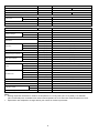
2.2
WH-SHF12D6E5 WH-UH12DE5
Item
Unit
Outdoor Unit
Performance Test Condition
EN14511
Condition
(Ambient/Water)
kW
Heating Capacity
12.00
12.00
41000
41000
kcal/h
10320
10320
W/W
4.40
3.23
kcal/hW
3.78
2.77
dB (A)
50
-
Power Level dB
67
3
Air Flow
3
m /min (ft /min)
Expansion Valve
3
Refrigeration Oil
cm
Refrigerant (R407C)
FV50S (1600)
kg (oz)
Height
mm (inch)
2.99 (105.5)
1340 (52-3/4)
Width
mm (inch)
900 (35-7/16)
Depth
mm (inch)
320 (12-19/32)
kg (lbs)
105 (232)
Liquid
mm (inch)
9.52 (3/8)
Gas
Net Weight
Pipe Diameter
80.0 (2830)
Refrigeration Control Device
Dimension
A2W35
BTU/h
COP
Noise Level
A7W35
mm (inch)
15.88 (5/8)
Standard Length
m (ft)
7 (23.0)
Pipe Length Range
m (ft)
3 (9.8) ~ 30 (98.4)
m (ft)
20 (65.6)
g/m (oz/ft)
70 (0.8)
I/D & O/D Height Difference
Additional Gas Amount
Refrigeration Charge Less
m (ft)
15 (49.2)
Type
Compressor
Hermetic Motor (Rotary)
Motor Type
Rated Output
Brushless (4-poles)
kW
3.00
Type
Propeller Fan
Material
Fan
PP
Motor Type
Input Power
Output Power
Fan Speed
Induction (8-poles)
W
—
W
60
rpm
520 (Top Fan) 560 (Bottom Fan)
Fin material
Heat Exchanger
Corrugated Fin
Row × Stage × FPI
Size (W × H × L)
Item
Power Source (Phase, Voltage, Cycle)
Power Supply 1: Phase / Max. Current / Max. Input
Power
Power Supply 2: Phase / Max. Current / Max. Input
Power
Power Supply 3: Phase / Max. Current / Max. Input
Power
Input Power
Maximum Input Power For Heat Pump System
Starting Current
Aluminium (Pre Coat)
Fin Type
2 × 51 × 19
mm
898.8 × 1295.4 × 38.1
Unit
ø
Single
V
230
Hz
50
ø/A/W
Single / 29.0 / 6.20k
ø/A/W
Single / 26.0 / 6.00k
ø/A/W
Single / 13.0 / 3.00k
kW
2.73
3.72
kW
6.20
A
13.0
7
Item
Unit
Running Current
A
Maximum Current For Heat Pump System
A
Power Factor
%
13.0
17.4
29.0
91
93
Power factor means total figure of compressor and outdoor fan motor.
Number of core
Power Cord
Length
m (ft)
-
Thermostat
Electronic Control
Protection Device
Electronic Control
Item
Unit
Indoor Unit
Performance Test Condition
Operation Range
EN14511
Outdoor Ambient
Water Outlet
Internal Pressure Differential
Noise Level
Dimension
Water Pipe Diameter
-20 ~ 35
°C
25 ~ 65
kPa
23.7
dB (A)
30
Power Level dB
43
Height
mm (inch)
892 (35-1/8)
Width
mm (inch)
502 (19-3/4)
Depth
mm (inch)
353 (13-29/32)
kg (lbs)
52 (115)
mm (inch)
9.52 (3/8)
Net Weight
Refrigerant Pipe Diameter
°C
Liquid
Gas
mm (inch)
15.88 (5/8)
Inlet
mm (inch)
28 (1-3/32)
Outlet
Water Drain Hose Inner Diameter
mm (inch)
28 (1-3/32)
mm (inch)
15.00 (19/32)
Motor Type
Pump
Capacitor Run Induction Motor (5 μF)
No. of Speed
3
Input Power
W
180
Type
Hot Water Coil
Brazed Plate
No. of Plates
100
Size (H x W x L)
mm
Water Flow Rate
l/min (m /h)
34.4 (2.1)
kPa
Open: 300, Close: 265 and below
Pressure Relief Valve Water Circuit
161 × 93 × 325
3
Flow Switch
Magnetic Lead Switch
Protection Device
Expansion Vessel
Capacity of Integrated Electric Heater
Volume
MWP
A
Residual Current Circuit Breaker / Earth Leakage Circuit Breaker (40)
I
10
bar
1
kW
6.00
Note:
Heating capacities are based on outdoor air temperature of 7°C Dry Bulb (44.6°F Dry Bulb), 6°C Wet Bulb
(42.8°F Wet Bulb) with controlled indoor water inlet temperature of 30°C and water outlet temperature of 35°C.
Specification are subjected to change without prior notice for further improvement.
8
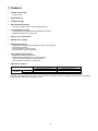
3. Features
Inverter Technology
High Efficiency
Compact Design
Environment Protection
Long Installation Piping
Easy to use control panel
Weekly Timer setting
Quality Improvement
Serviceability Improvement
Operation Condition
- Energy saving
- Non-ozone depletion substances refrigerant (R407C)
- Long piping up to 30 meter with height difference 20 meter
- Flexible 4-way piping for outdoor unit
-
-
Random auto restart after power failure for safety restart operation
Gas leakage protection
Prevent compressor reverse cycle
Inner protector to protect compressor
Breakdown Self Diagnosis function
System Status Check Buttons for servicing purpose
System Pumpdown Button for servicing purpose
Front maintenance design for outdoor unit
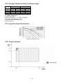
HEATING
Maximum
Minimum
Indoor
Water outlet temperature (°C)
65
25
Outdoor
Ambient temperature (°C)
35
-20
NOTICE : When the outdoor temperature is out of the above temperature range, the heating capacity will drop significantly
and outdoor unit might stop for protection control.
9
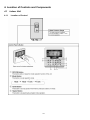
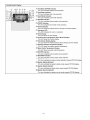
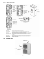
4. Location of Controls and Components
4.1
4.1.1
Indoor Unit
Location of Control
10
11
12
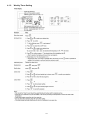
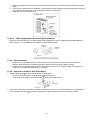
4.1.2
Weekly Timer Setting
13
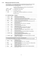
4.1.3
Setting Up the Special Functions
14
4.1.4
4.2
Main Components
Outdoor Unit
15
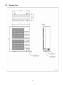
5. Dimensions
5.1
Indoor Unit
16
5.2
Outdoor Unit
17
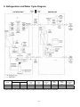
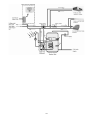
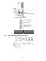
6. Refrigeration and Water Cycle Diagram
Piping size
Model
UH09DE5
UH12DE5
Gas
Liquid
5/8”
5/8”
3/8”
3/8”
Rated
Length
(m)
Common
Length
(m)
Max
Elevation
(m)
7
7
15
15
20
20
Min.
Piping
Length
(m)
3
3
* If piping length is over common length, additional refrigerant should be added as shown in the table.
18
Max.
Piping
Length
(m)
30
30
Additional
Refrigerant
(g/m)
70
70
19
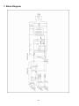
7. Block Diagram
20
8. Wiring Connection Diagram
8.1
8.1.1
Indoor Unit
WH-SHF09D3E5
21
8.1.2
WH-SHF12D6E5
22
8.2
Outdoor Unit
23
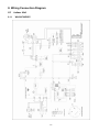
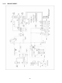
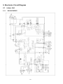
9. Electronic Circuit Diagram
9.1
9.1.1
Indoor Unit
WH-SHF09D3E5
24
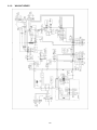
9.1.2
WH-SHF12D6E5
25
9.2
Outdoor Unit
26
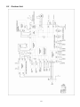
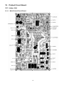
10. Printed Circuit Board
10.1 Indoor Unit
10.1.1 Main Printed Circuit Board
27
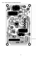
10.1.2 Solar Printed Circuit Board (Optional)
28
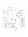
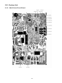
10.2 Outdoor Unit
10.2.1 Main Printed Circuit Board
29
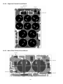
10.2.2 Capacitor Printed Circuit Board
10.2.3 Noise Filter Printed Circuit Board
30
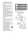
11. Installation Instruction
11.1
Select the Best Location
Indoor Unit
There should not be any heat source or steam
near the unit.
A place where air circulation in the room is good.
A place where drainage can be easily done.
A place where noise prevention is taken into
consideration.
Do not install the unit near the door way.
Ensure the spaces indicated by arrows from the
wall, ceiling, fence or other obstacles.
Recommended installation height for indoor unit
shall be at least 800 mm.
Must install on a vertical wall.
When install electrical equipment at wooden
building of metal lath or wire lath, according to
electrical facility technical standard, no electrical
contact between equipment and building is
allowed. Insulator must be installed in between.
Do not install the unit at outdoor. This is designed
for indoor installation only.
When connecting solar pump station cable
between indoor unit and solar pump station, the
distance between both apparatuses shall be 2 ~ 8
meters and the length of the said cable must be
shorter than 10 meter.
Fail to do so may lead to abnormal operation to
the system.
Piping size
AddiMax Min. Max.
tional
Rated
Eleva- Piping Piping
RefrigeLength
tion Length Length
Gas Liquid (m)
rant
(m)
(m)
(m)
(g/m)
Model
SHF09D3E5/
UH09DE5
ø15.88 ø9.52
mm mm 5~7.5
(5/8”) (3/8”)
20
3
30
70
SHF12D6E5/
UH12DE5
ø15.88 ø9.52
mm mm 5~7.5
(5/8”) (3/8”)
20
3
30
70
Example : For SHF12D6E5/UH12DE5
If piping length is 30m, the quantity of additional
refrigerant should be 1050g. [(30-15)m x 70 g/m =
1050g]
11.2
Outdoor Unit
If an awning is built over the unit to prevent direct
sunlight or rain, be careful that heat radiation from
the condenser is not obstructed.
Avoid location where ambient temperature is
below -20°C.
Keep the spaces indicated by arrows from wall,
ceiling, fence or other obstacles.
Do not place any obstacles which may cause a
short circuit of the discharged air.
If outdoor unit installed near sea, region with high
content of sulphur or oily location (e.g. machinary
oil, etc), it lifespan maybe shorten.
When installing the product in a
place where it will be affected by
typhoon or strong wind such as
wind blowing between buildings,
including the rooftop of a building
and a place where there is no
building in surroundings, fix the
product with an overturn prevention
wire, etc. (Overturn prevention
fitting model number: K-KYZP15C)
If piping length is over 15 m, additional refrigerant
should be added as shown in the table.
31
Indoor/Outdoor Unit
Installation Diagram
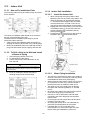
11.3
Indoor Unit
11.3.1 How to Fix Installation Plate
11.3.3 Indoor Unit Installation
The mounting wall is strong and solid enough to prevent
it from vibration.
11.3.3.1
1
2
3
The centre of installation plate should be at more than
551 mm at right and left of the wall.
The distance from installation plate edge to ground
should more than 1550 mm.
Always mount the installation plate horizontally by
aligning the marking thread and using a level gauge.
Mount the installation plate on the wall with 6 sets of
plug, bolt and washer (all non-supply) with size M8.
Install the Indoor Unit
When connecting solar pump station cable
between indoor unit and solar pump station, the
distance between both apparatuses shall be
2 ~ 8 meters and the length of the said cable
must be shorter than 10 meter. Fail to do so
may lead to abnormal operation to the system.
Engage the slots on the indoor unit to the hooks
of installation plate . Ensure the hooks are
properly seated on the installation plate by
moving it left and right.
Fix the screws
to the holes on the hooks of
installation plate, , as illustrated below.
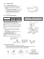
11.3.2 To Drill a Hole in the Wall and Install
a Sleeve of Piping
1
2
3
Insert the piping sleeve to the hole.
Fix the bushing to the sleeve.
Cut the sleeve until it extrudes about 15 mm
from the wall.
CAUTION
When the wall is hollow, please be sure to use the sleeve for
tube assembly to prevent dangers caused by mice biting the
connecting cable.
4
Finish by sealing the sleeve with putty or
caulking compound at the final stage.
11.3.3.2
32
Water Piping Installation
The minimum requirement of water in the system is
50 litres. If this value could not be achieved, please
install additional buffer tank (field supply).
Water inlet and water outlet in indoor unit are used
for connection to water circuit. Please request a
licensed technician to install this water circuit.
This water circuit must comply with all relevant
European and national regulations, i.e. IEC/EN
61770.
Be careful not to deform the piping with excessive
force when doing piping connection job.
Use Rp 1¼” nut for both water inlet and outlet
connection and clean all pipings with tap water
before install.
Cover the pipe end to prevent dirt and dust when
inserting it through a wall.
Choose proper sealer which can withstand the
pressures and temperatures of the system.
If existing tank is to be connected to this
indoor/outdoor unit, ensure the pipes are clean
before water pipe installation is carries out.
11.3.3.3
Install external filter (30 mesh or more, field supply)
before water inlet of indoor unit (with “WATER IN”
indication).
Refer to Diagram 4.1 for pipe connection of Panel
Heater, Floor Heater, Tank Unit, Solar Pump
Station, 3-way Valve Kit and etc. Fail to connect the
pipes appropriately might cause the unit malfunction.
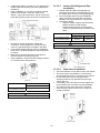
1
2
3
Indoor Unit Refrigerant Pipe
Installation
Please make flare after inserting flare nut
(located at joint portion of tube assembly) onto
the copper pipe. (In case of using long piping)
Do not use pipe wrench to open refrigerant
piping. Flare nut may be broken and cause
leakage. Use proper spanner or ring wrench.
Connect the piping:
o Align the center of piping and sufficiently
tighten the flare nut with fingers.
o Further tighten the flare nut with torque
wrench in specified torque as stated in the
table.
Model
SHF09D3E5/UH09DE5,
SHF12D6E5/UH12DE5
Be sure to use two spanners to tighten the
connection. Further tighten the nuts with torque
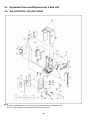
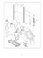
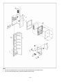
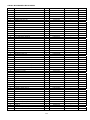
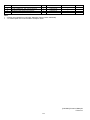
wrench in specified torque as stated in the table.
If non-brass metallic piping is used for installation,
make sure to insulate the pipes to prevent galvanic
corrosion.
Make sure to insulate the water circuit pipes to
prevent reduction of heating capacity.
After installation, check the water leakage condition
in connection area during test run.
ø 9.52mm (3/8”)
[42 N•m]
Do not over tighten, over tightening cause gas leakage.
(SHF09D3E5/UH09DE5,
SHF12D6E5/UH12DE5)
ø15.88mm (5/8”)
[65 N•m]
CAUTION
11.3.3.4
Model
Piping size (Torque)
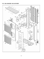
Gas
Liquid
Nut size (Torque)
Water
Rp 1 1/4” [117.6 N•m]
CAUTION
Do not over tighten, over tightening cause gas leakage.
33
Drain Hose Installation
Use inner diameter 15 mm drain hose in the market.
This hose must to be installed in a continuously
downward direction and in a frost-free environment.
Do not insert this hose into sewage hose or
cleaning hose that may generate ammonia gas,
sulfuric gas, etc.
If necessary, use hose clamp to further tighten the
hose at drain hose connector to prevent leakage.
The water may drip from drain hose. Therefore
must ensure the outlet of the hose is always not
closed or blocked.
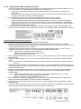
11.3.4 Connect the Cable to the Indoor Unit
1
2
3
Connecting cable between indoor unit and outdoor unit shall be approved polychloroprene sheathed 4 x 4.0
or 6.0 mm2 flexible cord, type designation 60245 IEC 57 or heavier cord.
o Ensure the colour of wires of outdoor unit and the terminal Nos. are the same to the indoor unit’s
respectively.
o Earth wire shall be longer than the other wires as shown in the figure for the electrical safety in case of
the slipping out of the cord from the Holder (Clamper).
Cable connection to the power supply through isolating device (Disconnecting means).
o Isolating device (Disconnecting means) should have minimum 3.0 mm contact gap.
o Connect the approved polychloroprene sheathed power supply 1 cord (3 x 4.0 or 6 mm2) and power
supply 2 cord (3 x 4.0 mm2) and power supply 3 cord (3 x 1.5 mm2) (Not applicable for SHF09D3E5),
type designation 60245 IEC 57 or heavier cord to the terminal board, and to the other end of the cord to
isolating device (Disconnecting means).
To avoid cable and cord harmed by sharp edge, cable and cord must go through bushing (located at the
bottom of indoor unit) before carry out electrical connection. The bushing must be used and must not take off.
Connecting with external device (optional)
1 All connections shall follow to the local national wiring standard.
2 It is strongly recommended to use manufacturer-recommended parts and accessories for installation.
3 Maximum output power of booster heater shall be 3kW. Booster Heater’ s cord must be (3 x min 1.5 mm2),
of type designation 60245 IEC 57 or heavier.
4 Three-Way Valve shall be spring and electronic type. Valve’s cable shall be (3 x min 0.5 mm2), of type
designation 60245 IEC 57 or heavier, or similarly double insulation sheathed cable.
* note: - Should be CE marking compliance component.
- It shall be directed to heating mode when it is OFF.
- Maximum load for the valve is 3VA.
5 Room Thermostat cable must be (4 or 3 x min 0.5 mm2), double insulation layer of PVC-sheathed or rubbersheathed cable.
6 Tank OLP cable must be (2 x min 0.5 mm2), double insulation layer of PVC-sheathed or rubber-sheathed
cable.
* note: if such connection deemed NO necessary for tank OLP, please connect jumper between terminal no.
13 and 14.
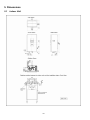
7 Tank Sensor shall be resistance type, please refer to Graph 5.1 for the characteristic and details of sensor. Its
cable shall be (2 x min 0.3 mm2), double insulation layer (with insulation strength of min 30V) of PVC-sheathed
or rubber-sheathed cable.
8 External Controller shall be connected to 1-pole switch with min 3.0 mm contact gap. (connection refer to
Diagram 5.2). Its cable must be (2 x min 0.5 mm2), double insulation layer of PVC-sheathed or rubbersheathed cable.
* note: - When making such connection, kindly remove the jumper between terminal no. 17 and 18.
- Switch used shall be CE marking compliance component.
- Maximum operating current shall be less than 3Arms.
9 Must install Solar Connection PCB
(optional) to indoor unit when Solar Pump Station is utilized. Refer
Solar Connection PCB installation instruction for detail of installation.
10 Solar Three-way Valve cable shall be (3 x min 0.5 mm2), double insulation layer PVC-sheathed or rubbersheathed cable.
2
11 Solar Pump Station cable shall be (2 x min 0.5 mm ), of double insulation PVC-sheathed or rubber-sheathed
cable. Strongly recommended install with maximum length of 10 meter only.
34
11.3.4.1
Terminal screw
Tightening torque N•cm {kgf•cm}
M4
157~196 {16~20}
M5
196~245 {20~25}
Wire Stripping and Connecting Requirement
35
11.3.4.2
Connecting Requirement
The equipment’s power supply 1 complies with IEC/EN 61000-3-12 provided that the short-circuit power Ssc is
greater than or equal to 1700.31kW (for SHF09D3E5/UH09DE5 and SHF12D6E5/UH12DE5) at the interface
point between the user’s supply and the public system. It is the responsibility of the installer or user of the
equipment to ensure, by consultation with the distribution network operator if necessary, that the equipment is
connected only to a supply with a short-circuit power Ssc greater than or equal to 1700.31kW.
The equipment’s power supply 1 shall be connected to a suitable supply network, having service current capacity
≥100A per phase. Please liaise with supply authority to ensure that the service current capacity at the interface
point is sufficient for the installation of the equipment.
The equipment’s power supply 2 complies with IEC/EN 61000-3-12.
The equipment’s power supply 2 shall be connected to a suitable supply network, with the following maximum
permissible system impedance Zmax at the interface for models:
SHF09D3E5/UH09DE5 and SHF12D6E5/UH12DE5 : 0.236 Ω
Please liaise with supply authority to ensure that the power supply 2 is connected only to a supply of that
impedance or less.
The equipment’s power supply 3 complies with IEC/EN 61000-3-12.
The equipment’s power supply 3 shall be connected to a suitable supply network, with the following maximum
permissible system impedance Zmax at the interface for models:
SHF09D3E5/UH09DE5 and SHF12D6E5/UH12DE5 : 0.464 Ω
Please liaise with supply authority to ensure that the power supply 3 is connected only to a supply of that
impedance or less.
36
11.4
Outdoor Unit
11.4.1 Install the Outdoor Unit
After selecting the best location, start installation
according to Indoor/Outdoor Unit Installation
Diagram.
1 Fix the unit on concrete or rigid frame firmly and
horizontally by bolt nut (ø10mm).
2 When installing at roof, please consider strong
wind and earthquake. Please fasten the
installation stand firmly with bolt or nails.
(Unit in mm)
11.4.2 Connecting the Piping
Model
SHF09D3E5/UH09DE5,
SHF12D6E5/UH12DE5
Piping size (Torque)
Gas
Liquid
ø15.88mm (5/8”)
[65 N•m]
ø9.52mm (3/8”)
[42 N•m]
CAUTION
Do not over tighten, over tightening cause gas leakage.
Connecting the Piping to Outdoor Unit
Decide piping length and then cut by using pipe cutter.
Remove burrs from cut edge. Make flare after
inserting the flare nut (locate at valve) onto the copper
pipe.
Align center of piping to valves and then tighten with
torque wrench to the specified torque as stated in the
table.
Local pipes can project in any of four directions.
Make holes in the pipe panels for the pipes to
pass through.
Be sure to install the pipe panels to prevent rain
from getting inside the outdoor unit.
[Removing the service panel].
(1) Remove the three mounting screws.
(2) Slide the service panel downward to release the
pawls.
After this, pull the service panel toward you to remove it.
Cutting and Flaring the Piping
1 Please cut using pipe cutter and then remove the burrs.
2 Remove the burrs by using reamer. If burrs is not removed, gas leakage may be caused.
Turn the piping end down to avoid the metal powder entering the pipe.
3 Please make flare after inserting the flare nut onto the copper pipes.
37
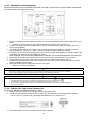
11.4.3 Evacuation of the Equipment
WHEN INSTALLING AN AIR-TO-WATER HEATPUMP, BE SURE TO EVACUATE THE AIR INSIDE THE INDOOR
UNIT AND PIPES in the following procedure.
1
2
3
4
5
6
7
8
Connect a charging hose with a push pin to the Low side of a charging set and the service port of the 3-way
valve.
o Be sure to connect the end of the charging hose with the push pin to the service port.
Connect the center hose of the charging set to a vacuum pump with check valve, or vacuum pump and
vacuum pump adaptor.
Turn on the power switch of the vacuum pump and make sure that the needle in the gauge moves from
0cmHg (0 MPa) to –76cmHg (–0.1 MPa). Then evacuate the air approximately ten minutes.
Close the Low side valve of the charging set and turn off the vacuum pump. Make sure that the needle in the
gauge does not move after approximately five minutes.
Note: BE SURE TO FOLLOW THIS PROCEDURE IN ORDER TO AVOID REFRIGERANT GAS LEAKAGE.
Disconnect the charging hose from the vacuum pump and from the service port of the 3-way valve.
Tighten the service port caps of the 3-way valve at a torque of 18N•m with a torque wrench.
Remove the valve caps of both of the 2-way valve and 3-way valve. Position both of the valves to “OPEN”
using a hexagonal wrench (4mm).
Mount valve caps onto the 2-way valve and the 3-way valve.
o Be sure to check for gas leakage.
CAUTION
Do not add or replace other than R407C type. It may cause product damage, burst, injury and etc. Use compatible
R410A tools for refrigerant piping work and refrigerant charging during installation or servicing.
CAUTION
If gauge needle does not move from 0cmHg (0MPa) to –76cmHg (–0.1MPa), in step
above take the following measure:
If the leak stops when the piping connections are tightened further, continue working from step .
If the leak does not stop when the connections are retightened, repair the location of leak.
Do not release refrigerant during piping work for installation and reinstallation. Take care of the liquid refrigerant,
it may cause frostbite.
11.4.4 Connect the Cable to the Outdoor Unit
(FOR DETAIL REFER TO WIRING DIAGRAM AT UNIT)
1 Remove the control board cover from the unit by loosening the screw.
2 Connecting cable between indoor unit and outdoor unit shall be approved polychloroprene sheathed
4 x (4.0 or 6.0 mm2) flexible cord, type designation 60245 IEC 57 or heavier cord.
3
Secure the cable onto the control board with the holder (clamper).
38
4
5
6
Select required direction and apply protective bushing provided in accessories to protect cables from sharp
edges.
Once all wiring work has been completed, tie the cables and cord together with the binding strap so that they
do not touch other parts such as the compressor and bare copper pipes.
Install back the control board cover.
11.4.4.1
Wire Stripping and Connecting Requirement
Same as indoor requirement. For details please refer the diagram on AIR-TO-WATER HEATPUMP INDOOR
UNIT, section 11.3.4 (CONNECT THE CABLE TO THE INDOOR UNIT).
11.4.5 Pipe Insulation
1
2
Please carry out insulation at pipe connection portion as mentioned in Indoor/Outdoor Unit Installation
Diagram. Please wrap the insulated piping end to prevent water from going inside the piping.
If drain hose or connecting piping is in the room (where dew may form), please increase the insulation by
using POLY-E FOAM with thickness 6 mm or above.
11.4.6 Disposal of Outdoor Unit Drain Water
When a Drain elbow
is used, please ensure to follow below:
o the unit should be placed on a stand which is taller than 50 mm.
o cover the 8 holes (ø20mm) with Rubber cap
(refer to illustration below.)
If the unit is used in an area where temperature falls below 0°C for 2 or 3 consecutive days, it is recommended
not to use the Drain elbow
and Rubber cap , for the drain water freezes and the fan will not rotate.
39
12. Operation and Control
12.1 Basic Function
Inverter control, which equipped with a microcomputer in determining the most suitable operating mode as time
passes, automatically adjusts output power for maximum comfort always. In order to achieve the suitable operating
mode, the microcomputer maintains the set temperature by measuring the temperature of the environment and
performing temperature shifting. The compressor at outdoor unit is operating following the frequency instructed by
the microcomputer at indoor unit that judging the condition according to internal water setting temperature and water
outlet temperature.
12.1.1 Internal Water Setting Temperature
Once the operation starts, control panel setting temperature will be taken as base value for temperature shifting
processes. These shifting processes are depending on the Air-to-Water Heatpump settings and the operation
environment. The final shifted value will be used as internal water setting temperature and it is updated continuously
whenever the electrical power is supplied to the unit.
12.1.2 Heating Operation
12.1.2.1
Thermostat control
Compressor is OFF when Water Outlet Temperature - Internal Water Setting Temperature > 2°C for continuously
3 minutes.
Compressor is ON after waiting for 3 minutes, if the Water Outlet Temperature - Water Inlet Temperature
(temperature at thermostat OFF is triggered) < -3°C.
12.1.3 Tank Mode Operation
Control contents:
3 ways valve direction
- 3 ways valve switch and fix to tank side.
Heat pump Thermostat characteristic
- Water set temperature = Tank set temperature or [60°C] whichever lower.
- Heat pump Water Outlet set temperature is set to Maximum (63°C) at tank mode
i. Case 1
- THERMO OFF TEMP:
1 THERMO OFF TEMP = Water set temperature + [0°C].
2 Tank temperature > THERMO OFF TEMP for continuous 3 minutes, heat pump OFF and water pump OFF.
- THERMO ON TEMP:
1 THERMO ON TEMP = Water set temperature + [-2°C].
When detect tank temperature < THERMO ON TEMP, water pump ON for 3 minutes then heat pump ON.
ii. Case 2
- Heat pump THERMO OFF TEMP:
1 Heat pump THERMO OFF TEMP = 63°C + [+4°C].
2 Water outlet temperature > Heat pump THERMO OFF TEMP for continuous 3 minutes, heat pump OFF.
- Heat pump THERMO ON TEMP:
1 Heat pump THERMO ON TEMP = Water inlet during thermo off time + [-3°C].
2 Heat pump ON back when water outlet temperature < Heat pump THERMO ON TEMP.
iii. Case 3
- Heat pump THERMO OFF TEMP:
1 Water inlet temperature > 65°C for continuous 60 secs, heat pump OFF.
- Heat pump THERMO ON TEMP:
1 Heat pump THERMO ON TEMP = Water inlet temperature < 65°C.
40
Booster heater control
- Booster heater turn On and Off follow normal operation.
- Booster heater turn ON condition:
1 During startup time (initialization), Booster heater turn ON after DELAY TIMER.
2 When tank temperature lower than HEATER ON TEMP
3 20 minutes from previous heater off.
- Booster heater turn OFF condition:
1 When tank temperature higher than tank set temperature for continuous 15 secs.
Solar 3 way valve
- Solar pump operates follow solar operation specification.
2 way valve closes
Others
- Indoor backup heater cannot be ON during tank mode only.
12.1.4 Heat + Tank Mode Operation
Setting 1: When Heating priority is set by control panel:
1 3 ways valve control:
o 3 ways valve switch to room side during External Room Thermo ON OR Solar 3ways valve ON OR Tank
Thermo OFF time, and switch to tank side at External Room Thermo OFF AND Solar 3 ways valve OFF
2
o
o
Heat pump operation control:During External Room Thermo ON time: (When room thermo ON, heat pump must operate to room
side)
Heat pump operate follow normal operation at room side
During External Room Thermo OFF time:
Switch 3 ways valve to tank side, IF
Under Solar Priority Set condition:
o Tank temperature < Tank THERMO ON TEMP AND Solar Valve OFF
Under Solar Priority Not Set condition:
o Tank temperature < Tank THERMO ON TEMP
Switch back 3 ways valve to room side, Heat pump and water pump turn OFF, IF
o External Room Thermo ON back OR
Under Solar Priority Set condition:
Tank temperature > Tank THERMO OFF TEMP. for continuous 3 minutes OR Solar Valve
ON
Under Solar Priority Not Set condition:
Tank temperature > Tank THERMO OFF TEMP for continuous 3 minutes
* THERMO ON and THERMO OFF point refer to case below.
Operation condition when 3 ways valve switch to tank side:
Tank water set temperature = tank set temperature or [60°C] whichever lower
Heat Pump Water Outlet set temperature is set to [63°C] during tank interval
Initial Tank THERMO ON TEMP = heat pump tank target temperature + [-2°C]
Case 1:
o THERMO OFF TEMP:
1. THERMO OFF TEMP = Heat pump tank target temperature + [0°C].
2. Tank temperature > THERMO OFF TEMP for continuous 10 minutes after compressor off, switch 3
ways valve to room side.
o
Next THERMO ON TEMP:
1. THERMO ON TEMP = Heat pump tank target temperature + [-2°C] or
2. If tank temperature < THERMO ON TEMP AND External Room Thermo OFF, switch to tank side.
41
Case 2:
o Heat pump THERMO OFF TEMP:
1. Heat pump THERMO OFF TEMP = 63°C + [+4°C].
2. Water outlet temperature > Heat pump THERMO OFF TEMP for continuous 3 minutes, heat pump
OFF.
o
Next THERMO ON TEMP:
1. THERMO ON TEMP = Water inlet when heat pump THERMO OFF + [-3°C].
2. If water outlet temperature < THERMO ON TEMP AND External Room Thermo OFF, heat pump ON.
Case 3:
o Heat pump THERMO OFF TEMP:
1. Water inlet temperature > 65°C for continuous 60 secs, heat pump OFF.
o
Next THERMO ON TEMP:
1. THERMO ON TEMP = Water inlet temperature < 65°C.
2. If water inlet temperature < THERMO ON TEMP AND External Room Thermo OFF, heat pump ON.
Case 4: (Only during solar priority is set condition)
o When solar request ON, solar valve will ON and switch 3 ways valve to room side
o
THERMO ON TEMP:
1. THERMO ON TEMP = Heat pump tank target temperature + [-2°C].
2. If tank temperature < THERMO ON TEMP AND External Room Thermo OFF AND Solar 3WV OFF,
switch to tank side.
3
o
o
Backup Heater control:During External Room Thermo ON time, follow normal backup heater control operation
During External Room Thermo OFF time, Backup heater OFF
o
Booster heater control:
Booster heater On/Off follow normal operation.
4
* Under solar priority is set condition, when solar 3 way valve is ON, booster heater turn OFF.
5
o
Solar 3 way valve:
Solar 3 way valve operates follow solar operation specification.
* Under solar priority is set condition, when solar 3WV turn ON, booster heater will turn OFF and 3 ways
valve switch to room side.
* Under solar priority is not set condition, solar 3WV will OFF when heat pump operate to tank side.
o
2 way valve opens.
Setting 2: When heating priority is not set by control panel:
When Solar Priority is set / not set by control panel:
1
3 ways valve control:
o 3 ways valve switch to room side during heating heat-up interval, and switch to tank side during tank
heat-up interval. Both mode will switch alternatively. Tank mode is the Initial running mode of this heat +
tank mode (heating no priority).
2
Heat pump operation control:
o During heating heat-up interval
- Follow normal heating operation.
Under solar priority set condition:
- Switch to tank heat-up interval and start counting tank heat-up timer when External Room Thermo
OFF AND solar 3WV OFF AND Tank temperature < THERMO ON TEMP (End Room Interval
Early) OR
- Switch to tank heat-up interval and start counting tank heat-up timer when tank temperature <
THERMO ON TEMP AND solar 3WV OFF after room heat-up timer complete
Under solar priority not set condition:
- Switch to tank heat-up interval and start counting tank heat-up timer when External Room Thermo
OFF AND Tank temperature < THERMO ON TEMP (End Room Interval Early) OR
42
- Switch to tank heat-up interval and start counting tank heat-up timer when tank temperature <
THERMO ON TEMP after room heat-up interval timer complete
* THERMO ON TEMP is defined form following Case1 to Case4.
o
During tank heat-up interval
- Heat pump tank target temperature = Tank set temperature or [60°C] whichever lower
- Heat pump Water Outlet set temperature is set to Maximum [65°C] during tank interval
- Initial Tank THERMO ON TEMP = heat pump tank target temperature + [-2°C]
Case 1:
- THERMO OFF TEMP:
1. THERMO OFF TEMP = Heat pump tank target temperature + [0°C].
2. Tank temperature > THERMO OFF TEMP for continuous 10 seconds after heat pump off due to water
thermo, switch 3 ways valve to room side. End Tank heat-up interval and start count heating heat-up
interval.
- THERMO ON TEMP:
1. THERMO ON TEMP = Heat pump tank target temperature + [-2°C].
2. After Heating heat-up interval, always detect tank temperature. Switch to next tank heat-up interval
when tank temperature < THERMO ON TEMP
Case 2:
- Heat pump THERMO OFF TEMP:
1. Heat pump THERMO OFF TEMP = 53°C + [+4°C].
2. Water outlet temperature > Heat pump THERMO OFF TEMP for continuous 3 minutes, heat pump
OFF.
- THERMO ON TEMP:
1. THERMO ON TEMP = Water inlet temperature, when heat pump thermo off + [-3°C].
Case 3:
- Heat pump THERMO OFF TEMP:
1. Water inlet temperature > 60°C for continuous 60 secs, heat pump OFF.
- THERMO ON TEMP:
1. THERMO ON TEMP = Water inlet temperature < 65°C.
Case 4 (Only during solar priority is set condition):
When solar pump ON, tank heat-up interval end early and 3 ways valve switch to room side.
- THERMO ON TEMP:
1. THERMO ON TEMP = Heat pump tank target temperature + [-2°C].
2. After Heating heat-up interval, always detect tank temperature. Switch to next tank heat-up interval
when tank temperature < THERMO ON TEMP and solar 3 way valve OFF.
- Tank interval will end and start heating interval timer, IF
1. Tank interval timer finish AND External Room Thermo ON OR
2. Fulfill above Case 1 of thermo off condition.
3
Backup heater control:
o During heating heat up interval.
- Follow normal backup heater control operation.
o During tank heat-up interval.
- Backup heater OFF during this interval.
4
Booster heater control:
o During heating heat-up interval.
- Booster heater ON/OFF according to booster heater operation control.
o During tank heat-up interval.
- Once switch from heating heat-up interval to tank heat-up interval, turn off the booster heater and start
counting the BOOSTER HEATER DELAY TIMER.
- Booster heater turn ON after BOOSTER HEATER DELAY TIMER fulfill and tank temperature lower
than tank set temperature.
- BOOSTER HEATER DELAY TIMER is clear when switch to heating heat-up interval.
43
5
Solar 3 way valve:
o Solar 3WV operates follow solar operation specification.
* Under solar priority is set condition, when solar 3WV is ON, booster heater turn OFF
* Under solar priority is not set condition, solar 3WV only can ON during heating heat-up interval.
6
2 way valve opens.
12.1.5 Setting Water Outlet Temperature for Heat Mode
The set temperature define the parameters for the outdoor ambient temperature dependent operation of the unit.
Where by the internal water setting temperature is determined automatically depending on the outdoor
temperature. The colder outdoor temperatures will result in warmer water and vice versa. The user has the
possibility to shift up or down the target water temperature by control panel setting.
Change in setting water outlet temperature is updated every 30 minutes.
12.1.5.1
Heating Mode Operation Time Chart
Operation of heat pump provide heating capacity to room side by hot water through heating panel, floor or fan
coil.
1
2
3
4
5
3 ways valve control:
o 3 ways valve switch and fix to heating side.
Heat pump operate follow normal heating operation.
Backup heater operate follow normal operation.
Solar 3 way valve operates follow solar operation specification.
2 way valve opens.
12.1.6 Water Temperature Thermo Shift Setting
Switchs are ignored during “PUMPDW” = ON.
Switchs are ignored during “STATUS” = ON.
“▲”, “▼”, “SELECT” switch are ignored if “SETTING” = OFF.
“CANCEL” switch is ignored if “SETTING” = OFF & “STATUS” = OFF.
If “SET” Switch pressed for less than 5secs, immediately enter water temperature shift setting mode.
Once enter this setting mode, “SETTING” display is ON.
This setting mode is used to easily shift the target water outlet temperature.
44
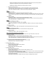
12.1.7 Outdoor Fan Motor Operation
Outdoor fan motor is adjusted according to operation condition. It starts when compressor starts operation and it
stops 30 seconds after compressor stops operation.
45
12.2
Water Pump
12.2.1 Water Pump Control
1
2
3
4
5
6
Once the indoor unit is ON, the water pump will be ON immediately and no error judgement for 9 minutes.
However, during this 9 minutes operation, if there is any abnormality cause at outdoor or malfunction, the
compressor should be OFF immediately and restart delay after 3 minutes.
The system will start checking on the water flow level after operation start for 9 minutes. If water flow level is
detected low continuously for 10 secs, the water pump and compressor will be OFF permanently and
OFF/ON control panel LED will blink (H62 error occurs).
When error happen, the power has to be reset to clear the error.
If there is no error indication, The water pump shall be continuously running.
The water pump will remain ON when compressor OFF due to thermostat OFF setting is reached.
Pump ON-OFF control
a. During operation OFF or water pump stop at Tank Mode
b. During ERROR stop
c. Water flowing flag = ON
d. Outdoor air temperature < 30°C
When above [(a) or (b)] and (c) and (d) conditions fulfilled,
PUMP ON for 4 minutes, and OFF for 55 minutes continuously
When any of below mentioned condition below is achieved, this control is cancelled
f.
Operation = ON (except during water pump stop at tank mode)
g. Water pump run at tank mode
h. Change from tank mode to another mode during water pump stop at tank mode
i.
Outdoor air temperature ≥ 32°C
j.
Water inlet temperature < 38°C for 30 minutes continuously
46
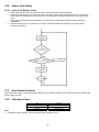
12.3
Pump Down Operation
Purpose
Ensure the pump down operation when relocating or disposing of the unit. The pump down operation will extract all
refrigerant from the piping into the outdoor unit.
Pump down operation control:
1 Press the SERVICE S/W for continuous 5 secs to enter Service mode.
2 In service mode, select Sr:01 and press SET S/W to start Pump Down operation.
3 There will be no Low Pressure error & Freeze prevention judgement during pumpdown operation.
4 3 ways valve will shift to room side.
5 Press the ON/OFF button to stop the unit.
12.4
Flow Switch
12.4.1 Flow Switch Control
1
2
12.5
The water flow switch serve as an overload protector that shuts down the unit when the water level is
detected to be low.
Detection is Lo (0V) when there is no water flow, and detection is Hi (5V) when there is water flow.
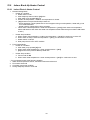
Force Heater Mode Operation
The backup heater also serves as backup in case of malfunctioning of the outdoor unit.
1 Make sure the OFF/ON control panel LED is OFF (no operation).
2 Press the Force button to start the force heater mode operation.
3 During force heater mode, all other operations are not allowed.
4 Press OFF/ON button to stop the force heater mode operation.
47
12.6
Indoor Unit Safety
12.6.1 Indoor Unit Safety Control
1
2
3
12.7
When water pump is ON, the system will start checking flow switch status (ON/OFF).
If the flow switch ON for 10 seconds, the system will check on the water inlet temperature for 10 seconds.
If the water inlet temperature not exceeds 80°C, the water pump shall be continuously running with normal
mode.
If the water inlet temperature exceeds 80°C for continuously 10 seconds, the water pump will be OFF
immediately.
After water pump OFF for more than 10 minutes, it will be ON back and the indoor unit safety control
checking is restarted.
Auto Restart Control
When the power supply is cut off during the operation of Air-to-Water Heatpump, the compressor will re-operate after
power supply resumes.
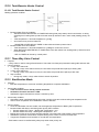
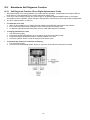
12.8
Indication Panel
LED
Color
Light ON
Light OFF
Operation
Green
Operation ON
Operation OFF
Note:
If Operation LED is blinking, there is an abnormality operation occurs.
48
12.9
Indoor Back-Up Heater Control
12.9.1 Indoor Electric Heater Control
1
Normal Heating Mode
o Heater On condition:
a. Heater switch is ON
b. After Heatpump thermo ON for [30] mins
c. After water pump operate [9] mins
d. Outdoor air temperature < Outdoor set temperature for heater
e. [20] minutes since previous Backup heater Off
* When heatpump cannot operate due to error happens during normal operation, heater will go into
force mode automatic
* Heater need to operate during deice operation
f. When water outlet temperature < Water set temperature + [-8°C] (check water out temperature
before ON heater 3 and check also water out temperature after heater delay timer before ON heater
2 and 1)
o
2
Heater Stop Condition:
a. When outdoor set temperature > outdoor set temperature + [+2°C] for continuous 15 secs OR
b. When water out temp> water set temperature + [-2°C] for continuous 15 secs OR
c. Heater switch is Off OR
d. Heat pump thermo-off or OFF condition
Force Heater Mode
o Heater On Condition:
a. After water pump operate [9] mins
b. When water outlet temperature < water set temperature + [-8°C]
c. [20] minutes since previous Backup heater Off
o
Heater Stop condition
a. Force mode off OR
b. When water outlet temperature > water set temperature + [-2°C] for continuous 15 secs
* Do not operate heater at the following situation
1 Water outlet temperature sensor, and water inlet sensor abnormal
2 Flow switch abnormal
3 Circulation pump stop condition
4 During Heatpump switch to tank side
49
12.10 Tank Booster Heater Control
12.10.1 Tank Booster Heater Control
Heating operation condition:
1
2
Booster heater Turn On condition:
o After BOOSTER HEATER DELAY TIMER fulfill during heat pump startup time in tank mode, or during
switching from heating heat-up interval to tank heat-up interval in heat + tank mode (heating priority not
set).
o Tank temperature < Tank set temperature + [-5°C],
o 20 minutes since previous heater off.
* BOOSTER HEATER DELAY TIMER is clear when tank heat-up interval end.
Booster heater Turn Off condition:
o Tank temperature > Tank set temperature + [+2°C] for continuous 15 secs
o When BOOSTER HEATER DELAY TIMER start count after switch from heating heat-up interval to tank
heat-up interval
* DELAY TIMER can be set by control panel.
12.11 Three Way Valve Control
Purpose:
- 3 ways valve is used to change flow direction of hot water from heat pump between heating side and tank side
Control contents:
1 3 ways valve switch Off:
o During 3 ways valve switch Off time, the hot water will provide heat capacity to heating side.
2 3 ways valve switch On:
o During 3 ways valve switch On time, the hot water will provide heat capacity to tank side.
3 Stop condition:
o During stop mode, 3 ways valve will be in switch off position
12.12 Sterillization Mode
Purpose:
o Boil tank temperature to customer set boiling temperature to operate sterilization.
Control start condition:
o Tank connection set to YES by remote controlller
o Serilization function selection is YES
o Sterilization signal received from remote controller by timer.
Control stop condition:
o After boiling timer completed. Boiling timer start counting once tank achieve boiling set temperature OR
o After 4 hours of operation since sterilization function start OR
Control content:
o Once the sterilization function enable, set the target tank temperature to Boiling Set Temperature.
o Booster heater will allow to ON during solar priority SET condition.
Booster heater OFF Temp. = Boiling Set Temperature + 2°C
Booster heater ON Temp. = Boiling Set Temperature - 5°C
o Boiling timer which set by remote controller will start count after tank achieve boiling set temperature.
o Sterilization operation will end after complete boiling timer or Max 4 hrs from function start.
o Target tank temperature will set back to normal tank set temperature.
* Tank heater control is not affected by solar pump when solar priority set.
50
12.13 Quiet Operation
Purpose:
- To provide quiet operation compare to normal operation by reduces outdoor unit noise.
Starting condition:
1 When quiet button is presses.
2 When quiet request ON time by weekly timer (Refer to control panel.)
When any of above mentioned condition is achieved, this control is activated.
New target FM speed = Present target FM speed - 80 rpm
Minimum target FM speed = 200 rpm
Cancellation condition:
1 Cancel by press quiet button
2 Stop by OFF/ON button
3 When quiet request OFF time by weekly timer
When any of above mentioned condition is achieved, this control is cancelled.
12.14 Solar Operation (Optional)
12.14.1 Solar Operation
1
2
3
4
External solar heat source signal can be connect to unit for proper control of heat source switching during
tank boiling time.
Control according to preset whether solar priority is set or not.
When tank connection is NOT set at SETTING mode, solar operation is disabled.
When Pump A (from solar pump station) is detected On through connection Y3 and Y4, then the Solar pump
3 Way Valve is requested ON (Refer to figure below).
12.14.2 Solar Operation Control
When solar priority is SET
1 Operation condition:
a
Solar pump operates if all of the following conditions are fulfilled:
Power On. (regardless operation ON or OFF)
There is operation request from solar pump station.
Tank hot water temp is below solar on upper limit temp 80°C.
2 Stop condition:
a
Solar pump stops operating when:
No power supply to unit OR
There is NO operation request from solar pump station OR
Tank hot water temp is above solar off upper limit temp 72°C.
* heat pump OFF OR operate to room side when solar pump operate during solar priority set.
* booster heater OFF when solar pump operate during solar priority set.
51
When solar priority is NOT SET
1 Operation condition:
a
Solar pump operates if all of the following conditions are fulfilled:
Power On. (regardless operation ON or OFF).
There is operation request from solar pump station.
Tank hot water temp is below solar on upper limit temp 80°C.
Heat pump thermo OFF in tank mode OR Heat pump operate to room side
(during operation ON and tank mode selected).
2
Stop condition:
a
Solar pump stops operating when:
No power supply to unit OR
There is NO operation request from solar pump station OR
Tank hot water temp is above solar off upper limit temp 72°C.
Heat pump thermo ON and operate to tank side. (during operation ON and tank mode selected).
52
53
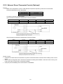
12.15 External Room Thermostat Control (Optional)
Purpose:
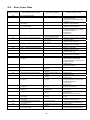
1 Better room temperature control to fulfill different temperature request by external room thermostat.
Recommended external room thermostat:
Maker
Siemen (REV200)
Siemen (RAA20)
Characteristic
Touch panel
Analog
Connection external room thermostat:
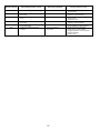
Wire Connection and thermo characteristic of Siemen REV200:
Setting
Set Temp < Actual Temp
Set Temp > Actual Temp
L/L1 (H)
Open Circuit
Short Circuit
Heat Thermo
OFF
ON
L/L2 (C)
Short Circuit
Open Circuit
Cool Thermo
ON
OFF
L/Y2 (C)
Short Circuit
Open Circuit
Cool Thermo
ON
OFF
Wire Connection and thermo characteristic of Siemen RAA20:
Setting
Set Temp < Actual Temp
Set Temp > Actual Temp
L/Y1 (H)
Open Circuit
Short Circuit
Heat Thermo
OFF
ON
Control Content:
External room thermostat control activate only when remote thermostat connection select YES by Indoor control
panel.
When indoor running heat mode, refer thermo On/Off from heating line feedback. And when indoor running cool
mode, refer thermo On/Off from cooling line feedback.
Heat pump Off immediately when receive thermo off feedback.
54
13. Protection Control
13.1
Protection Control for All Operations
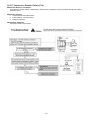
13.1.1 Time Delay Safety Control
1
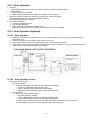
The compressor will not start for three minutes after stop of operation.
13.1.2 30 Seconds Forced Operation
1
2
Once the compressor starts operation, it will not stop its operation for 30 seconds.
However, it can be stopped using control panel at indoor unit.
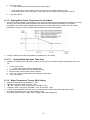
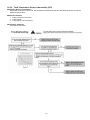
13.1.3 Total Running Current Control
1
2
3
When the outdoor running current exceeds X value, the compressor frequency will decrease.
If the outdoor running current does not exceed X value, the compressor frequency will return to normal
operating frequency.
If the outdoor running current continue to increase till exceed Y value, compressor will stop, and if this occurs
3 times within 20 minutes, system will stop operation and OFF/ON control panel LED will blink (F16 error
occurs).
09D
Operation Mode
Heating
X (A)
24.0
12D
Y (A)
30.0
X (A)
28.0
Y (A)
30.0
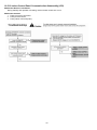
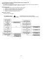
13.1.4 IPM (Power Transistor) Prevention Control
A. Overheating Prevention Control
1 When the IPM temperature rises to 95°C, compressor will stop immediately.
2 Compressor will restart delay 3 minutes when the IPM temperature decreases to 90°C.
If this condition repeats continuously 3 times within 30 minutes, system will stop operation and OFF/ON
control panel LED will blink (F22 error occurs).
B. DC Peak Current Control
1 When the current to IPM exceeds set value of 53.5 ± 5.0 A, compressor will stop. Compressor will restart
after three minutes.
2 If the set value exceeds again for more than 30 seconds after the compressor restarts, operation will restart
after two minutes.
3 If the set value exceeds again for within 30 seconds after the compressor restarts, operation will restart after
one minute. If this condition repeats continuously for seven times, system will stop operation and OFF/ON
control panel LED will blink (F23 error occurs).
13.1.5 Compressor Overheating Prevention Control
The compressor operating frequency is regulated in accordance to compressor tank temperature as shown in
below figures. When the compressor tank temperature exceeds 112°C, compressor will stop, and if this occurs
4 times within 30 minutes, system will stop operation and OFF/ON control panel LED will blink (F20 error occurs).
55
13.1.6 Low Pressure Protection Control
Purpose:
o To protect the system operation.
o Detection period:
After compressor on for 5 minutes.
o Detection conditions:
When detection of Tem above 30°C.
Calculation of average evaporation temperature (Tem).
Use outdoor low pressure sensor.
Tem use the value calculated for discharge temperature setting value
o After detection:
Compressor stops restart again after 3 mins.
When abnormalities continuously generated 60 times within 480 minutes
Protection is prohibited.
Error H42 will be displayed.
13.1.7 High Pressure Sensor Control / Low Pressure Sensor
Purpose:
- To protect the system operation.
Detection period:
- After compressor on for 1 minute.
Detection conditions:
- When abnormal high voltage detection, 5V or when open circuit detection 0V for 5 seconds continuously.
After detection:
- When abnormality is detected continue 5 seconds, unit stop operation.
- OFF/ON control panel LED will blink (H64 error occurs).
13.1.8 Outside Temperature Current Control
13.1.9 Extreme Low Temperature Control
Purpose:
- To improve the compressor reliability during cold start and after deice when running in extreme low outdoor
temperature -20°C.
Starting condition:
1 Heating operation
2 Outdoor air temperature < -10°C
3 Actual frequency ≥ 50Hz
4 Compressor discharge temperature < 20°C
When the above condition is fulfilled, this control is activated.
5Hz up every 30 sec. until it reaches the target frequency.
Cancellation condition:
- starting condition not fulfill.
- Cancel the extreme low temperature control when compressor discharge sensor ≥ 60°C
56
13.1.10 Crank Case Heater Control
Purpose:
- For compressor protection during low outdoor ambient operation (during heating low temperature operation).
Control content:
a. Trigger heater START condition
o When the outdoor air temperature is 13°C or below, and discharge temperature is 13.2°C or below.
b. Resetting heater STOP condition
1. when the outdoor air temperature exceeds entry condition (15°C).
2. when the discharge temperature exceeds entry condition (20.2°C).
13.2
Protection Control for Heating Operation
13.2.1 Outdoor Air Temperature Control
The maximum current value is regulated when the outdoor air temperature rises above 14°C in order to avoid
compressor overloading.
13.2.2 Deice Operation
When outdoor pipe temperature and outdoor air temperature is low, deice operation start where outdoor fan motor
stop.
57
14. Servicing Mode
14.1
How to Take Out Front Plate
Please follow the steps below for take out front plate. Before removing the front plate of indoor unit, always
switch off all power supply (i.e. indoor unit power supply, heater power supply and tank unit power supply).
1 Remove the 2 mounting screws which located at bottom of the front plate and 1 mounting screw at the front
of the plate.
2 Gently pull the lower section of the front plate towards you to remove the front plate from left and right hooks.
3 Hold the left edge and right edge of front plate to lift up front plate from hooks.
14.2 How to Take Out Side Cabinet
Please follow the steps below to remove the side
cabinet. Before removing the front plate of indoor
unit always switch off all power supply (i.e. indoor
power supply, heater power supply and tank unit
power supply).
1 Perform the steps in HOW TO TAKE OUT
FRONT PLATE.
2 Remove all the 13 mounting screws on the left,
right and top of the side cabinet.
3 Gently remove the side cabinet by holding
both of the handles.
14.3
1
2
3
4
14.4
Test Run
Fill up the boiler tank with water. For details refer to boiler tanks installation instruction and operation
instruction.
Set ON to the indoor unit and RCCB/ELCB. Then, for control panel’s operation please refers to air-to-water
heatpump’s operation instruction.
For normal operation, pressure gauge reading should be in between 0.05 MPa and 0.3 MPa.
If necessary, adjust the water pump speed accordingly to obtain normal water pressure operating range. If
adjust water pump speed cannot solve the problem, contact your local authorized dealer.
After test run, please clean the external filter. Reinstall it after finish cleaning.
Proper Pump Down Procedure
Strictly follow the steps below for proper pump down procedure. Explosion may occur if the steps are not
followed as per sequence.
1 Press the “SERVICE” switch on control panel to enter SERVICE mode. Operate the system in Sr :
01 mode for pump down operation.
2 After 10~15 minutes, (after 1 or 2 minutes in case very low ambient temperatures (< 10°C)), fully close
2 way valve.
3 After 3 minutes, fully close 3 way valve.
4 Press the “OFF/ON” switch on control panel to stop pump down operation.
5 Remove the refrigerant piping.
58
14.5
How to Adjust Water Flow Rate
Before adjust the water flow rate, make sure that the total water volume in the installation is 50 litres minimum.
The water flow rate can be adjusted with select the water pump speed on the water pump. The default setting is
moderate speed (II). However, please ensure the minimum flow rate cannot be less than 18L/min. Adjust it to
high speed (III) and slow speed (I) if necessary (e.g. reduce the noise of running water).
Below graph shown the external static pressure (kPa) versus water flow rate (L/min).
Flow rate characteristic of indoor unit is as per above mentioned.
14.6
Expansion Vessel Pre Pressure Checking
Expansion Vessel with 10L air capacity and initial pressure of 1 bar is installed in this indoor unit.
Total amount of water in system should be below 200L.
(Note: This amount of water is not include the tank unit volume)
If total amount of water is over 200L, please add expansion vessel.
Please keep the installation height difference of system water circuit within 10m.
(Inner volume of same indoor unit is about 5L)
59
15. Maintenance Guide
In order to ensure optimal performance of the unit, checks and inspections on the unit and the field wiring must be
carried out regularly.
Before carried out any maintenance or repair work, and removing the front plate of heat exchanger unit, always
switch off all power supply (i.e. indoor unit power supply, heater power supply and sanitary tank power supply).
Below checks must be carried out at least once a year.
1
2
Water pressure
Water pressure should not lower than 0.05 MPa (with inspects the pressure gauge). If necessary add tap
water into boiler tank. Refer to boiler tank installation instruction for details on how to add water.
Pressure relief valve
o Check for correction operation of pressure relief valve by turn up the lever to become horizontal. (Refer
to figure below)
o If you do not hear a clacking sound (due to water drainage), contact your local authorized dealer.
o Turn down the lever after checking finish.
o In case the water keeps drained out from the unit, switch off the system, and then contact your local
authorized dealer.
3
Air purge valve
Air purge valve must be installed at all high points in a closed water circuit system.
An automatic air purge valve is provided inside the indoor unit. To automatically purge the air from the
system, turn the plug on the air outlet anticlockwise by one complete turn from fully closed position.
Excessive air is automatically purged if the plug is kept in this position.
4
Indoor unit control board area
Thorough visual inspection of the control board and look for defects, i.e. loose connection, melting of wire
insulator and etc.
RCCB/ELCB
Ensure the RCCB/ELCB set to “ON” condition before check RCCB/ELCB.
Turn on the power supply to the indoor unit.
This testing could only be done when power is supplied to the indoor unit.
5
WARNING
Be careful not to touch parts other than RCCB/ELCB test button when the power is supplied to Indoor Unit. Else, electrical
shock may happen.
o
o
o
o
Push the “TEST” button on the RCCB/ELCB. The lever would turn down and indicate “0” and indicate
green colour if it functions normal.
Contact authorized dealer if the RCCB/ELCB malfunction.
Turn off the power supply to the indoor unit.
If RCCB/ELCB functions normal, set the lever to “ON” again after testing finish.
60
6
Reset overload protector
Overload protector serves the safety purpose to prevent the water over heating. When the overload protector
trip at high water temperature, take below steps to reset it.
a. Take out OLP cover.
b. Use a test pen to push the centre button gently in order to reset the Overload protector.
c. After finish, install back the Overload protector following the reverse order of step a & b.
7
External water filter (field supply)
Clean the external water filter in regularly basic.
o External water filter is located inside the tube connector which is before water inlet connector of indoor
unit (indicated with “WATER IN”). (Refer to figure below)
o Use spanner to detach the tube connector nut.
o Take out the filter carefully so that not deforms it shape.
o Use tap water only to wash the residue on the filter. If necessary, gently use soft brush only to clean the
hard dirt.
o After clean, put it back to the original location and tighten the nut connection with torque wrench.
61
16. Troubleshooting Guide
16.1
Refrigeration Cycle System
In order to diagnose malfunctions, make sure that there
are no electrical problems before inspecting the
refrigeration cycle.
Such problems include insufficient insulation, problem
with the power source, malfunction of a compressor and a
fan.
The normal pressure of the refrigeration cycle depends
on various conditions, the standard values for them are
shown in the table on the right.
62
16.2
Relationship between the Condition of the Air-to-Water Heatpump
Indoor and Outdoor Units and Pressure and Electric Current
Heating Mode
Condition of the
Air-to-Water Heatpump indoor and outdoor
units
Low Pressure
High Pressure
Electric current during operation
Water leakage or insufficient water flow
rate in the system
Excessive amount of refrigerant
Inefficient compression
Insufficient refrigerant
(gas leakage)
Outdoor heat exchange deficiency
Clogged expansion valve or Strainer
Carry out the measurements of pressure, electric current, and temperature fifteen minutes after an operation is
started.
63
16.3
Breakdown Self Diagnosis Function
16.3.1 Self Diagnosis Function (Three Digits Alphanumeric Code)
When abnormality occur during operation, the system will stop operation, and OFF/ON control panel LED will
blink and error code will display on the control panel timer display LCD.
Even error code is reset by turning OFF power supply or by pressing ERROR RESET button, if the system
abnormality is still un-repaired, system will again stop operation, and OFF/ON control panel LED will again blink.
The error code will store in IC memory.
To check the error code
1 When an abnormality occurs, system will stop operation and OFF/ON control panel LED will blink.
2 Error code of the abnormality will display on the control panel timer display LCD.
3 To determine the abnormality description, the error code table needs to be referred.
To display past/last error code
1 Turn ON power supply.
2 Press and hold the CHECK button for more than 5 seconds to enter status mode.
3 Press the SEARCH DOWN/UP button to retrieve past/last error code.
4 Press the CANCEL button or wait 30 seconds to exit status mode.
To permanently delete error code from IC memory
1 Turn ON power supply.
2 Press and hold the ERROR RESET button for more than 8 seconds till a beep sound is heard.
64
16.4
Error Codes Table
Diagnosis display
Abnormality/Protection control
Abnormality judgement
H00
H12
No abnormality detected
Indoor/Outdoor capacity unmatched
—
continue for 90 sec.
H15
Continue for 90 sec.
H42
Outdoor compressor temperature sensor
abnormality
Indoor refrigerant liquid temperature
sensor abnormality
Compressor low pressure abnormality
H62
Water flow switch abnormality
H63
Refrigerant low pressure abnormality
H64
Refrigerant high pressure abnormality
H70
Back-up heater OLP abnormality
9 minutes after water pump ON
and continue for 1 minute
4 times occurrence within
20 minutes
4 times occurrence in
20 minutes
Continue for 60 sec.
H72
H76
H90
Tank sensor abnormal
Indoor - control panel communication
abnormality
Indoor/outdoor abnormal communication
> 1 min after starting operation
H91
Tank heater OLP abnormality
Continue for 60 sec.
H95
H98
Indoor/Outdoor wrong connection
Outdoor high pressure overload
protection
H99
Indoor heat exchanger freeze prevention
Continue for 10 sec.
F12
Pressure switch activate
F14
Outdoor compressor abnormal revolution
F15
Outdoor fan motor lock abnormality
F16
Total running current protection
F20
Outdoor compressor overheating
protection
4 times occurrence within 20
minutes
4 times occurrence within 20
minutes
2 times occurrence within 20
minutes
3 times occurrence within 20
minutes
4 times occurrence within 30
minutes
F22
IPM (power transistor) overheating
protection
Outdoor Direct Current (DC) peak
detection
Refrigeration cycle abnormality
3 times occurrence within 30
minutes
7 times occurrence
continuously
2 times occurrence within 20
minutes
Cooling/Heating cycle changeover
abnormality
Indoor water inlet temperature sensor
abnormality
Outdoor discharge pipe temperature
sensor abnormality
PFC control
4 times occurrence within 30
minutes
Continue for 5 sec.
H23
F23
F24
F25
F37
F40
F41
F42
Outdoor heat exchanger temperature
sensor abnormality
Continue for 5 sec.
—
Continue for 5 sec.
—
—
—
Continue for 5 sec.
4 times occurrence within 10
minutes
Continue for 5 sec.
65
Primary location to verify
—
Indoor/outdoor connection wire
Indoor/outdoor PCB
Specification and combination table in
catalogue
Compressor temperature sensor
(defective or disconnected)
Refrigerant liquid temperature sensor
(defective or disconnected)
Outdoor pipe temperature sensor
Clogged expansion valve or strainer
Insufficient refrigerant
Outdoor PCB
Compressor
Water flow switch
Outdoor low pressure sensor (defective
or disconnected)
Outdoor high pressure sensor
(defective or disconnected)
Back-up heater OLP
(Disconnection or activated)
Tank sensor
Indoor - control panel
(defective or disconnected)
Internal/external cable connections
Indoor/Outdoor PCB
Tank heater OLP
(Disconnection or activated)
Indoor/Outdoor supply voltage
Outdoor high pressure sensor
Water pump or water leakage
Clogged expansion valve or strainer
Excess refrigerant
Outdoor PCB
Indoor heat exchanger
Refrigerant shortage
Pressure switch
Outdoor compressor
Outdoor PCB
Outdoor fan motor
Excess refrigerant
Outdoor PCB
Compressor tank temperature sensor
Clogged expansion valve or strainer
Insufficient refrigerant
Outdoor PCB
Compressor
Improper heat exchange
IPM (Power transistor)
Outdoor PCB
Compressor
Insufficient refrigerant
Outdoor PCB
Compressor low compression
4-way valve
V-coil
Water inlet temperature sensor
(defective or disconnected)
Outdoor discharge pipe temperature
sensor (defective or disconnected)
Voltage at PFC
Outdoor heat exchanger temperature
sensor (defective or disconnected)
Diagnosis display
Abnormality/Protection control
Abnormality judgement
F43
Outdoor defrost sensor abnormality
Continue for 5 sec.
F45
Indoor water outlet temperature sensor
abnormality
Outdoor Current Transformer open
circuit
Continue for 5 sec.
Outdoor EVA outlet temperature sensor
abnormality
Outdoor bypass outlet temperature
sensor abnormality
Cooling high pressure overload
protection
Continue for 5 sec.
F46
F48
F49
F95
—
Continue for 5 sec.
4 times occurrence in
20 minutes.
66
Primary location to verify
Outdoor defrost sensor (defective or
disconnected)
Water outlet temperature sensor
(defective or disconnected)
Insufficient refrigerant
Outdoor PCB
Compressor low
Outdoor EVA outlet temperature sensor
(defective or disconnected)
Outdoor bypass outlet temperature
sensor (defective or disconnected)
Outdoor high pressure sensor
Water pump or water leakage
Clogged expansion valve or strainer
Excess refrigerant
Outdoor PCB
16.5
Self-diagnosis Method
16.5.1 Connection Capability Rank Abnormality (H12)
Malfunction Decision Conditions:
During startup operation of heating, the capability rank of indoor checked by the outdoor is used to determine
connection capability rank abnormality.
Malfunction Caused:
1 Wrong model interconnected.
2 Wrong indoor unit or outdoor unit PCB (main) used.
3 Faulty indoor unit or outdoor unit PCB (main).
Abnormality Judgment:
Continue for 90 seconds.
67
16.5.2 Compressor Tank Temperature Sensor Abnormality (H15)
Malfunction Decision Conditions:
During startup and operation of heating, the temperatures detected by the compressor tank temperature sensor
are used to determine sensor error.
Malfunction Caused:
1 Faulty connector connection.
2 Faulty sensor.
3 Faulty outdoor unit PCB (main).
Abnormality Judgment:
Continue for 5 seconds.
68
16.5.3 Indoor Refrigerant Liquid Temperature Sensor Abnormality (H23)
Malfunction Decision Conditions:
During startup and operation of heating, the temperatures detected by the indoor refrigerant liquid temperature
sensor are used to determine sensor error.
Malfunction Caused:
1 Faulty connector connection.
2 Faulty sensor.
3 Faulty indoor unit PCB (main).
Abnormality Judgment:
Continue for 5 seconds.
69
16.5.4 Compressor Low Pressure Protection (H42)
Malfunction Decision Conditions:
During operation of heating and after 5 minutes compressor ON, when outdoor pipe temperature below -29°C or
above 26°C is detected by the outdoor pipe temperature sensor.
Malfunction Caused:
1 Dust accumulation on the outdoor unit heat exchanger.
2 Air short circuit at outdoor unit.
3 3 way valve partially closed.
4 Faulty outdoor unit fan motor.
5 Refrigerant shortage (refrigerant leakage).
6 Clogged expansion valve or strainer.
7 Faulty outdoor pipe temperature sensor.
8 Faulty outdoor unit main PCB (main).
70
16.5.5 Water Flow Switch Abnormality (H62)
Malfunction Decision Conditions:
During operation of heating, the water flow detected by the indoor water flow switch is used to determine water
flow error.
Malfunction Caused:
1 Air trapped in water system.
2 Faulty water pump.
3 Water leak in system.
4 Faulty connector connection.
5 Faulty water flow switch.
6 Faulty indoor unit PCB (main).
Abnormality Judgment:
Continue for 10 seconds (but no judgment for 9 minutes after compressor startup/restart).
71
16.5.6 Outdoor Low Pressure Abnormality (H63)
Malfunction Decision Conditions:
During operation of heating, when the outdoor low pressure sensor output signal is 0Vdc or 5Vdc.
Malfunction Caused:
1 Faulty connector connection.
2 Faulty sensor.
3 Faulty outdoor unit PCB (main).
Abnormality Judgment:
Continue 4 times in 20 minutes.
72
16.5.7 Outdoor High Pressure Abnormality (H64)
Malfunction Decision Conditions:
During operation of heating, when the outdoor high pressure sensor output signal is 0Vdc or 5Vdc.
Malfunction Caused:
1 Faulty connector connection.
2 Faulty sensor.
3 Faulty outdoor unit PCB (main).
Abnormality Judgment:
Continue 4 times in 20 minutes.
73
16.5.8 Indoor Backup Heater OLP Abnormality (H70)
Malfunction Decision Conditions:
During operation of indoor backup heater, when no power supplies to indoor backup heater or OLP open circuit.
Malfunction Caused:
1 Faulty power supply connector connection.
2 Faulty connector connection.
3 Faulty indoor backup heater overload protector (OLP).
4 Faulty indoor unit PCB (main).
Abnormality Judgment:
Continue for 60 seconds.
74
16.5.9 Tank Temperature Sensor Abnormality (H72)
Malfunction Decision Conditions:
When tank connection is set to ON, the temperatures detected by the tank temperature sensor are used to
determine sensor error.
Malfunction Caused:
1 Faulty connector connection.
2 Faulty sensor.
3 Faulty indoor unit PCB (main).
Abnormality Judgment:
Continue for 5 seconds.
75
16.5.10 Indoor-Control Panel Communication Abnormality (H76)
Malfunction Decision Conditions:
During standby and operation of heating, indoor-remote control error occur.
Malfunction Caused:
1 Faulty connector connection.
2 Faulty remote control.
3 Faulty indoor unit PCB (main).
76
16.5.11 Indoor/Outdoor Abnormal Communication (H90)
Malfunction Decision Conditions:
During operation of heating, the data received from outdoor unit in indoor unit signal transmission is checked
whether it is normal.
Malfunction Caused:
1 Faulty outdoor unit PCB (main).
2 Faulty indoor unit PCB (main).
3 Indoor-outdoor signal transmission error due to wrong wiring.
4 Indoor-outdoor signal transmission error due to breaking of wire in the connection wires between the indoor
and outdoor units.
5 Indoor-outdoor signal transmission error due to disturbed power supply waveform.
Abnormality Judgment:
Continue for 1 minute after operation.
77
16.5.12 Tank Booster Heater OLP Abnormality (H91)
Malfunction Decision Conditions:
During operation of tank booster heater, and tank booster heater OLP open circuit.
Malfunction Caused:
1 Faulty connector connection.
2 Faulty tank booster heater overload protector (OLP).
3 Faulty indoor unit PCB (main).
Abnormality Judgment:
Continue for 60 seconds.
78
16.5.13 Unspecified Voltage between Indoor and Outdoor (H95)
Malfunction Decision Conditions:
The supply power is detected for its requirement by the indoor/outdoor transmission.
Malfunction Caused:
1 Insufficient power supply.
2 Faulty outdoor unit PCB (noise filter/main).
79
16.5.14 Outdoor High Pressure Protection (H98)
Malfunction Decision Conditions:
During operation of heating, when pressure 4.0 MPa and above is detected by outdoor high pressure sensor.
Malfunction Caused:
1 Faulty water pump.
2 Insufficient water flow rate in system.
3 Water leak in system.
4 3 way closed.
5 Clogged expansion valve or strainer.
6 Excessive refrigerant.
7 Faulty outdoor high pressure sensor.
8 Faulty outdoor unit PCB (main).
80
16.5.15 Indoor Freeze-up Protection (H99)
Malfunction Decision Conditions:
During anti-freezing control in cooling operation, when the indoor refrigerant liquid temperature < 0°C.
Malfunction Caused:
1 Faulty water pump.
2 Insufficient water flow rate in system.
3 Water leak in system.
4 2 way valve partially closed.
5 Clogged expansion valve or strainer.
6 Refrigerant shortage (refrigerant leakage).
7 Faulty indoor refrigerant liquid temperature sensor.
8 Faulty indoor unit PCB (main).
81
16.5.16 Outdoor High Pressure Switch Activate (F12)
Malfunction Decision Conditions:
During operation of heating, when pressure 4.5MPa and above is detected by outdoor high pressure switch.
Malfunction Caused:
1 Faulty water pump.
2 Insufficient water flow rate in system.
3 Water leak in system.
4 3 way valve closed.
5 Clogged expansion valve or strainer.
6 Excessive refrigerant.
7 Faulty outdoor high pressure sensor and switch.
8 Faulty outdoor unit PCB.
Abnormality Judgment:
Continue 4 times in 20 minutes.
82
16.5.17 Compressor Rotation Failure (F14)
Malfunction Decision Conditions:
A compressor rotation failure is detected by checking the compressor running condition through the position
detection circuit.
Malfunction Caused:
1 Compressor terminal disconnect.
2 Faulty outdoor unit PCB (main).
3 Faulty compressor.
Abnormality Judgment:
Continue 4 times in 20 minutes.
83
16.5.18 Outdoor Fan Motor (DC Motor) Mechanism Locked (F15)
Malfunction Decision Conditions:
The rotation speed detected by the Hall IC of the fan motor during fan motor operation is used to determine
abnormal fan motor (feedback of rotation > 2550rpm or < 50rpm).
Malfunction Caused:
1 Operation stop due to short circuit inside the fan motor winding.
2 Operation stop due to breaking of wire inside the fan motor.
3 Operation stop due to breaking of fan motor lead wires.
4 Operation stop due to fan motor Hall IC malfunction.
5 Operation error due to faulty outdoor unit PCB.
Abnormality Judgment:
Continue 2 times in 30 minutes.
84
16.5.19 Input Over Current Detection (F16)
Malfunction Decision Conditions:
During operation of heating, when outdoor current above 27.9A is detected by the current transformer (CT) in the
outdoor unit PCB.
Malfunction Caused:
1 Excessive refrigerant.
2 Faulty outdoor unit PCB (main).
Abnormality Judgment:
Continue 3 times in 20 minutes.
85
16.5.20 Compressor Overheating (F20)
Malfunction Decision Conditions:
During operation of heating, when temperature above 112°C is detected by the compressor tank temperature
sensor.
Malfunction Caused:
1 Faulty compressor tank temperature sensor.
2 3 way valve closed.
3 Refrigerant shortage (refrigerant leakage).
4 Clogged expansion valve or strainer.
5 Faulty outdoor unit PCB (main).
6 Faulty compressor.
Abnormality Judgment:
Continue 4 times in 30 minutes.
86
16.5.21 IPM Overheating (F22)
Malfunction Decision Conditions:
During operation of heating, when temperature 95°C is detected by the outdoor IPM temperature sensor.
Malfunction Caused:
1 Faulty outdoor unit fan motor.
2 Faulty outdoor unit PCB (main).
Abnormality Judgment:
Continue 3 times in 30 minutes.
87
16.5.22 Output Over Current Detection (F23)
Malfunction Decision Conditions:
During operation of heating, when outdoor DC current is above 40.1 ± 5.0A (for: 6kW~9kW) OR 44.7 ± 5.0A
(for: 12kW~16kW) is detected by the IPM DC Peak sensing circuitry in the outdoor unit PCB (main).
Malfunction Caused:
1 Faulty outdoor unit PCB (main).
2 Faulty compressor.
Abnormality Judgment:
Continue for 7 times.
88
16.5.23 Refrigeration Cycle Abnormality (F24)
Malfunction Decision Conditions:
1 During operation of heating, compressor frequency > Frated.
2 During operation of heating, running current: 0.65A < I < 1.65A.
3 During operation of heating, indoor refrigerant liquid temperature - water inlet temperature < 5°C.
Malfunction Caused:
1 Faulty water inlet or indoor refrigerant liquid temperature sensors.
2 3 way valve closed.
3 Refrigerant shortage (refrigerant leakage).
4 Clogged expansion valve or strainer.
5 Faulty outdoor unit PCB (main).
6 Poor compression of compressor.
Abnormality Judgment:
Continue 2 times in 20 minutes.
89
16.5.24 Four Way Valve Abnormality (F25)
Malfunction Decision Conditions:
During heating operation, when the indoor pipe temperature of thermostat ON indoor unit < 0°C.
Malfunction Caused:
1 Faulty sensor.
2 Faulty connector connection.
3 Faulty outdoor unit PCB (noise filter/main).
4 Faulty four way valve.
Abnormality Judgment:
Continue 4 times in 30 minutes.
90
16.5.25 Outdoor High Pressure Switch Abnormal (F27)
Malfunction Decision Conditions:
During compressor stop, and outdoor high pressure switch is remain opened.
Malfunction Caused:
1 Faulty connector connection.
2 Faulty switch.
3 Faulty outdoor unit PCB (main).
Abnormality Judgment:
Continue for 1 minute.
91
16.5.26 Outdoor Air Temperature Sensor Abnormality (F36)
Malfunction Decision Conditions:
During startup and operation of heating, the temperatures detected by the outdoor air temperature sensor are
used to determine sensor error.
Malfunction Caused:
1 Faulty connector connection.
2 Faulty sensor.
3 Faulty outdoor unit PCB (main).
Abnormality Judgment:
Continue for 5 seconds.
92
16.5.27 Indoor Water Inlet Temperature Sensor Abnormality (F37)
Malfunction Decision Conditions:
During startup and operation of heating, the temperatures detected by the indoor water inlet temperature sensor
are used to determine sensor error.
Malfunction Caused:
1 Faulty connector connection.
2 Faulty sensor.
3 Faulty indoor unit PCB (main).
Abnormality Judgment:
Continue for 5 seconds.
93
16.5.28 Outdoor Discharge Pipe Temperature Sensor Abnormality (F40)
Malfunction Decision Conditions:
During startup and operation of heating, the temperatures detected by the outdoor discharge pipe temperature
sensor are used to determine sensor error.
Malfunction Caused:
1 Faulty connector connection.
2 Faulty sensor.
3 Faulty outdoor unit PCB (main).
Abnormality Judgment:
Continue for 5 seconds.
94
16.5.29 Power Factor Correction (PFC) Abnormality (F41)
Malfunction Decision Conditions:
During operation of heating, when the PFC protection circuitry in the outdoor unit PCB (main) senses abnormal
high DC voltage level.
Malfunction Caused:
1 Power supply surge.
2 Compressor windings not uniform.
3 Faulty outdoor unit PCB (main).
Abnormality Judgment:
Continue 4 times in 10 minutes.
95
16.5.30 Outdoor Pipe Temperature Sensor Abnormality (F42)
Malfunction Decision Conditions:
During startup and operation of heating, the temperatures detected by the outdoor pipe temperature sensor are
used to determine sensor error.
Malfunction Caused:
1 Faulty connector connection.
2 Faulty sensor.
3 Faulty outdoor unit PCB (main).
Abnormality Judgment:
Continue for 5 seconds.
96
16.5.31 Outdoor Defrost Temperature Sensor Abnormality (F43)
Malfunction Decision Conditions:
During startup and operation of heating, the temperatures detected by the outdoor defrost temperature sensor
are used to determine sensor error.
Malfunction Caused:
1 Faulty connector connection.
2 Faulty sensor.
3 Faulty outdoor unit PCB (main).
Abnormality Judgment:
Continue for 5 seconds.
97
16.5.32 Indoor Water Outlet Temperature Sensor Abnormality (F45)
Malfunction Decision Conditions:
During startup and operation of heating, the temperatures detected by the indoor water outlet temperature sensor
are used to determine sensor errors.
Malfunction Caused:
1 Faulty connector connection.
2 Faulty sensor.
3 Faulty indoor unit PCB (main).
Abnormality Judgment:
Continue for 5 seconds.
98
16.5.33 Outdoor Current Transformer Open Circuit (F46)
Malfunction Decision Conditions:
A current transformer (CT) open circuit is detected by checking the compressor running frequency (≥ rated
frequency) and CT detected input current (< 0.65A) for continuously 20 seconds.
Malfunction Caused:
1 CT defective.
2 Faulty outdoor unit PCB.
3 Compressor defective (low compression).
Abnormality Judgment:
Continue 3 times in 20 seconds.
99
16.5.34 Cooling High Pressure Overload Protection (F95)
Malfunction Decision Conditions:
During operation of cooling, when pressure 4.0MPa and above is detected by outdoor high pressure sensor.
Malfunction Caused:
1 Dust accumulation in the outdoor unit heat exchanger.
2 Air short circuit at outdoor unit.
3 2 way valve closed.
4 Faulty outdoor unit fan motor.
5 Clogged expansion valve or strainer.
6 Excessive refrigerant.
7 Faulty outdoor high pressure sensor.
8 Faulty outdoor unit PCB (main).
100
17. Disassembly and Assembly Instructions
WARNING
High Voltage are generated in the electrical parts area by the capacitor. Ensure that the capacitor has discharged sufficiently before proceeding
with repair work. Failure to heed this caution may result in electric shocks.
17.1 To Remove Front Plate
Please follow the steps below for take out front plate. Before removing the front plate of indoor unit, always
switch off all power supply (i.e. indoor unit power supply, heater power supply and tank unit power supply).
1 Remove the 2 mounting screws which located at bottom of the front plate and 1 mounting screw at the front
of the plate.
2 Gently pull the lower section of the front plate towards you to remove the front plate from left and right hooks.
3 Hold the left edge and right edge of front plate to lift up front plate from hooks.
17.2 To Remove Cabinet Side Plate
101
17.3 To Remove Pressure Gauge
17.4 To Remove Control Panel
102
17.5 To Remove RCCB/ELCB
17.6 To Remove Transformer and Electronic Controller Board
103
17.7 To Remove Air Purge Valve, Pressure Relief Valve, Flow Switch, Water
Pump and Bottle Complete
When reinstall the water pipe, use grease or water at the joining.
104
When reinstall the water pipe, use grease or water at the joining.
When reinstall the water pipe, use grease or water at the joining.
105
18. Technical Data
18.1 Heating Capacity Table
18.1.1 WH-SHF09D3E5 WH-UH09DE5
LWC
Tamb
-15
-7
2
7
16
25
HC
9000
9000
9000
9000
9000
12000
30
LWC
Tamb
-15
-7
2
7
16
25
HC
8600
8900
9000
9000
9000
10600
35
IP
3500
3100
2470
1860
1500
1700
HC
9000
9000
9000
9000
9000
12000
IP
4650
4150
3590
2800
2400
2500
HC
8500
8900
9000
9000
9000
10200
50
40
IP
3750
3330
2650
1980
1600
1800
HC
8900
9000
9000
9000
9000
12000
IP
4950
4500
3920
3100
2700
2700
HC
8000
8900
9000
9000
9000
10000
55
45
IP
4050
3600
2950
2250
1850
2050
HC
8800
8900
9000
9000
9000
10800
IP
5100
5000
4390
3500
3150
2950
HC
7800
8900
9000
9000
9000
9800
IP
5550
4950
3900
3100
2560
2050
HC
10600
11200
11300
12000
12000
12000
IP
6050
5700
5350
4900
4350
3450
HC
8000
9600
10300
12000
12000
12000
60
IP
4300
3870
3250
2500
2100
2180
65
IP
5900
5500
4800
4000
3600
3350
HC: Heating Capacity (kW)
IP: Power Input (kW)
LWC: Leaving Water Condenser Temperature (°C)
Tamb: Ambient Temperature (°C)
Piping Length: 7m
18.1.2 WH-SHF12D6E5 WH-UH12DE5
LWC
Tamb
-15
-7
2
7
16
25
HC
12000
12000
12000
12000
12000
12000
30
LWC
Tamb
-15
-7
2
7
16
25
HC
10300
10800
11000
12000
12000
12000
35
IP
5200
4470
3460
2560
2070
1700
HC
12000
12000
12000
12000
12000
12000
IP
5670
5200
4550
3850
3450
2680
HC
9700
10100
10800
12000
12000
12000
50
40
IP
5570
4800
3720
2730
2210
1800
HC
11000
11500
11500
12000
12000
12000
IP
5800
5320
4900
4320
3900
3000
HC
9000
9850
10650
12000
12000
12000
55
45
60
HC: Heating Capacity (kW)
IP: Power Input (kW)
LWC: Leaving Water Condenser Temperature (°C)
Tamb: Ambient Temperature (°C)
Piping Length: 7m
106
IP
5570
5100
4180
3480
2900
2450
65
IP
6150
5950
5630
5450
4800
3900
18.2 Heating Capacity at Different Piping Length
Pipe Length
3
7
10
20
30
WH-SHF09
HC
IP
9000
1990
9000
1980
8000
1880
7400
1880
7000
1880
WH-SHF12
HC
IP
12000
2750
12000
2730
10300
2550
9500
2550
9000
2550
HC: Heating Capacity (kW)
IP: Power Input (kW)
Outdoor air temperature: 7°C (DBT), 6°C (WBT)
Indoor water inlet temperature: 30°C
Indoor water outlet temperature: 35°C
Piping Length: 7m
18.3 Hydraulic Pump Performance
18.4 Usage Limitation
107
19. Exploded View and Replacement Parts List
19.1 WH-SHF09D3E5 WH-SHF12D6E5
Note:
The above exploded view is for the purpose of parts disassembly and replacement.
The non-numbered parts are not kept as standard service parts.
108
< Model: WH-SHF09D3E5 WH-SHF12D6E5>
REF. NO.
DESCRIPTION & NAME
QTY.
WH-SHF09D3E5
WH-SHF12D6E5
1
BASE PAN
1
CWD521266
←
2
HOT WATER COIL-COMPLETE
1
CWB90C1035
←
3
RECEIVER
1
CWB141039
←
4
FLOAT (FLOW SWITCH)
1
CWB601008
←
5
TUBE CONNECTOR-COMPLETE
1
CWT29C1043
←
6
FLARE NUT (5/8)
1
CWT251061
←
7
FLARE NUT (7/8)
1
CWT251064
←
9
PUMP
1
CWB532096
←
10
PACKING (O-RING) I.D 32mm
2
CWB811082
←
REMARKS
O
O
O
11
PACKING (O-RING) I.D 13.8mm
2
CWB811022
←
12
RETAINING RING D:22mm
2
CWH581007
←
13
VALVE BODY (AIR TO WATER)
1
CWB621094
←
16
BOTTLE COMPLETE
1
CWH90C0027
CWH90C0028
17
HEATER ASS'Y
1
CWA34K1014
CWA34K1020
18
SOUND PROOF MATERIAL
1
CWG302595
CWG302702
19
THERMOSTAT
2/3
CWA151065
←
O
20
ELECTRONIC CONTROLLER-MAIN
1
CWA73C6516
CWA73C6517
O
21
TERMINAL BOARD ASS'Y
1
CWA28K1217
←
25
TERMINAL BOARD ASS'Y
1
CWA28K1229
←
26
TERMINAL BOARD ASS'Y
1
CWA28K1230
←
28
TERMINAL BOARD ASS'Y
1
CWA28K1231
←
29
RESIDUAL CURRENT CIRCUIT BREAKER
2/3
CWA181005
←
O
30
TRANSFORMER-COMPLETE
1
CWA40C1096
←
O
31
SENSOR-COMPLETE
1
CWA50C2762
←
O
32
REMOTE CONTROL COMPLETE
1
CWA75C3998
←
O
33
PRESSURE GAUGE
1
CWB070001
←
O
34
VALVE BODY (AIR TO WATER)
1
CWB621092
←
35
CABINET
1
CWE001050A
←
36
HANDLE
2
CWE161008
←
37
CABINET FRONT PLATE
1
CWE061265A
←
38
INSTALLING HOLDER
1
CWH361103A
←
39
OPERATING INSTRUCTION
1
CWF568253
←
40
OPERATING INSTRUCTION
1
CWF568677
←
41
INSTALLATION INSTRUCTION
1
CWF614964
←
42
ACCESSORY-COMPLETE
1
CWH82C1754
←
Note:
All parts are supplied from PAPAMY, Malaysia (Vendor Code: 00029488).
“O” marked parts are recommended to be kept in stock.
109
O
19.2 WH-UH09DE5 WH-UH12DE5
110
111
Note:
The above exploded view is for the purpose of parts disassembly and replacement.
The non-numbered parts are not kept as standard service parts.
112
< Model: WH-UH09DE5 WH-UH12DE5>
REF. NO.
DESCRIPTION & NAME
QTY.
WH-UH09DE5
WH-UH12DE5
1
BASE PAN ASS’Y
1
CWD52K1275
←
2
COMPRESSOR
1
4JD650XAA22
←
3
BUSHING - COMPRESSOR MOUNT
3
CWH50055
←
4
NUT-COMPRESSOR MOUNT
3
CWH561049
←
4a
PACKING
3
CWB811017
←
5
CRANKCASE HEATER
1
CWA341053
←
6
CONDENSER COMPLETE
1
CWB32C3494
←
7
HIGH PRESSURE SENSOR
1
CWA50C2570
←
8
DISCHARGE MUFFLER
1
CWB121014
←
9
PRESSURE SWITCH
1
CWA101013
←
10
3-WAYS VALVE (GAS)
1
CWB011251
←
11
4-WAYS VALVE
1
CWB001046
←
12
3-WAYS VALVE (LIQUID)
1
CWB011292
←
13
STRAINER
4
CWB111032
←
14
LOW PRESSURE SENSOR
1
CWA50C2571
←
19
ACCUMULATOR ASS'Y
1
CWB131026A
←
20
SOUND PROOF MATERIAL
1
CWG302265
←
21
SOUND PROOF MATERIAL
1
CWG302266
←
22
SOUND PROOF BOARD ASS'Y
1
CWH15K1019
←
REMARKS
O
23
V-COIL COMPLETE - 4-WAYS VALVE
1
CWA43C2169J
←
O
24
V-COIL COMPLETE - EXP.VALVE
1
CWA43C2478
←
O
25
SENSOR-COMP. TEMP COIL
1
CWA50C2730
←
26
SENSOR-COMP. DISCHARGE
1
CWA50C2576
←
27
SENSOR-COMP. TOP
1
CWA50C2629
←
27a
SENSOR-COMP. DEF
1
CWA50C2577
←
28
CABINET REAR PLATE-COMPLETE
1
CWE02C1067
←
29
CONTROL BOARD CASING
1
CWHH10K1049
←
31
TERMINAL BOARD ASS’Y
1
CWA28K1213
←
36
ELECTRONIC CONTROLLER (CAPACITOR)
1
CWA746082
←
O
38
ELECTRONIC CONTROLLER (NOISE FILTER)
1
CWA746991
←
O
44
ELECTRONIC CONTROLLER (MAIN)
1
CWA73C6518R
CWA73C6519R
O
46
REACTOR
1
G0C592J00006
←
48
TERMINAL COVER
1
CWH171054
←
49
NUT-TERMINAL COVER
1
CWH7080300J
←
50
FAN MOTOR BRACKET
1
CWD54K1024
←
50a
SCREW-FAN MOTOR BRACKET
2
CWH551040J
←
53
FAN MOTOR
1
EHDS80AAC
←
O
54
FAN MOTOR
1
EHDS80BAC
←
O
54a
SCREW-FAN MOTOR MOUNT
8
CWH551323
←
55
PROPELLER FAN ASSY
2
CWH00K1006
←
56
NUT FOR PROPELLER FAN
2
CWH561038J
←
57
CABINET FRONT PLATE
1
CWE061098A
←
58
DISCHARGE GRILLE
2
CWE201073
←
59
CABINET SIDE PLATE ASSY
1
CWE04K1023A
←
60
WIRE NET
1
CWD041103A
←
61
CABINET TOP PLATE CO.
1
CWE03C1096
←
62
ACCESSORY-COMPLETE
1
CWH82C1535
←
64
PIPE COVER (FRONT)
1
CWD601074A
←
65
PIPE COVER (BACK)
1
CWD601075A
←
66
CABINET FRONT PLATE CO.
1
CWE06C1091
←
67
HANDLE
2
CWE161008
←
68
TUBE ASSY (CAP.TUBE)
1
CWT07K1619
←
70
EXPANSION VALVE
2
CWB051029
←
113
REF. NO.
DESCRIPTION & NAME
QTY.
WH-UH09DE5
WH-UH12DE5
72
MAGNET RELAYS
1
K6C1AYY00003
←
73
V-COIL COMPLETE - EXP. VALVE (BYPASS)
1
CWA43C2335
←
74
SENSOR-COMP. TEMP COIL (BYPASS)
1
CWA50C2797
←
76
ACCESSORY CO.(DRAIN ELBOW)
1
CWG87C2030
←
REMARKS
Note:
All parts are supplied from PAPAMY, Malaysia (Vendor Code: 00029488).
“O” marked parts are recommended to be kept in stock.
[PAPAMY] Printed in Malaysia
FO0112-0
114