1
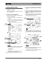
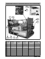
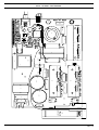
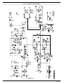
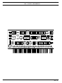
Language: English
MMA UNITS
125-130A
Date Creation: Jan. 2005
Rev.: 00
Service Manual
1105
INVERTERS MMA 130A
1.0 REPAIR INSTRUCTIONS
2. Check on all the harnesses the insulation of
the cables and the state at the connection
points.
1.1 GENERAL CLEANING
Remove the machine shell and clean carefully
with compressed air.
1.2 MACHINE: VISUAL INSPECTION
1. Check the general conditions of the electronic
circuit ref. 1, particularly:
• the varistor (RV1) (fig. 1) if it presents bursting marks
1.3 CHECK OF THE MAIN COMPONENTS WITH
TESTER (OHMMETER) ON THE CIRCUIT
REF. 1
1. Check for the presence of short circuits on the
rectifier bridge (VD1) and the correct value of
the power resistance (R14) (fig. 3).
R14
• the state of the levelling condensers C32
and C33 (fig. 2) check if there are swellings
or breaks on the container
RV1
VB1
FIG.3
RIF. 1
FIG. 1 REF. 1
1. IGBT of the primary circuit and diodes of recycle: test points G-C, G-E, C-E of components 1
and 2; points A-K of components 3 and 4 (fig.
4).
1
3
C32
2
4
C33
FIG. 2 REF. 1
• check for the presence of cracks or breaks
on the welds of the following components:
• transformer T1
• impedance L2
• the presence of burn tracks or electric discharge marks on the printed circuit
In case of faults, replace the electronic circuit ref. 1
1105
FIG. 4 RIF. 1
2. Diodes of the secondary circuit: check points
1-K of diodes VD1 and VD2 (fig. 5).
If there are short circuits or faults during these
tests, replace the electronic circuit.
Pag. 3
INVERTERS MMA 130A
VD1
VD2
FIG. 5 REF. 1
1.4 CHECK OF GENERATOR OPERATION
WITH OSCILLOSCOPE AND VOLTMETER
FIG. 8 REF. 1
2. Disconnect the feeder; set the oscilloscope
with a range of 1V/Div and connect the probe
X100 between points M and P (fig. 9); connect
the machine to the power supply, switch it on:
1. Connect a feeder on the zener V13 with GND
on the anode and supply with approx. 15Vdc;
set the oscilloscope on a time base of 5 uS
and a range of 0.5 V/Div with probe x10 and
verify:
• the presence between points: E (GND) - A
(probe) and F (GND) - B (probe) (fig. 6) of
the waveform shown in fig. 7: if the waveform differs from the one in the figure or it is
not present, the electronic circuit is broken.
Solution: board replacement ref. 1.
A
P
M
E
FIG.8 RIF. 1
B
• the motor fan starts up, and after approx. 2
seconds a wave will appear as in fig. 9.
F
FIG. 7 REF. 1
FIG. 9 REF.1
1105
Pag. 5
INVERTERS MMA 130A
• check with a voltmeter that the output voltage is approx. 47Vdc (see test specification
point 2).
• If the wave form does not appear or the output voltage is not correct, replace the electronic circuit ref. 1
Carry out the final test after the repair.
U
T
2.0 FINAL TEST
1. Carry out the safety test according to our operative instruction N. SLL12, before proceeding,
act as follows:
FIG. 10 RIF. 1
• on the electronic board (ref. 1) short-circuit
points U, T and a rheophore of the primary
circuit of the transformer (fig. 10)
PRIMARY CIRCUIT
OF THE TRASF.
• switch on
• short-circuit the feeder plug
• short-circuit the output dinse..
After the test remove all the short circuits and switch
off.
2. Connect the generator to the power supply
(230 Vac), switch it on and check if the voltage
of the outputs is 47 Vdc (+/- 5%): switch off the
generator.
3. Connect the generator to the resistive load: the
load must be regulated so that the voltage on
the load, with maximum current, is between
20V and 23V. Apply oscilloscope probe as in
fig. 8
4. Set the regulation knob to the centre of the
dial, switch on the generator, turn the knob to
the maximum welding current and read with
the amperometer the maximum current indicated on the technical table with +/- 5% tolerance. You will see on the oscilloscope a
waveform as in fig. 11.
5. If the current readings differ, use the trimmer T
(fig. 13) to obtain the correct current value.
FIG. 11 REF. 1
T
6. Short-circuit the load and verify that after 1,5
sec. the current descends to approx. 25A.
7. Regulate the resistive load to measure the
minimum current (5A - 20V), set the minimum
current on the frontal panel and check with the
amperometer that there is a value near than
the one indicated on the technical table.
FIG. 12 REF. 1
8. Disconnect the probe, switch off the generator
and with the load to the maximum current, let
the machine work at the greatest capacity.
9. Carry out MMA welding tests at maximum current (one electrode)
1105
Pag. 7
LISTA PEZZI DI RICAMBIO - SPARE PARTS LIST - PIÈCES DÉTACHÉES - ERSATZTEILLISTE - LISTA DE LAS PIEZAS DE RECAMBIO
06
05
11 09
56
12
08 72 14
01
SAXO 1300
R.
COD.
01
05
06
DESCRIZIONE
DESCRIPTION
DESCRIPTION
BESCHREIBUNG
DESCRIPCIÓN
W000050018
CIRCUITO ELETTRONICO CE 22599
CIRCUIT BOARD CE
22599
CIRCUIT ÉLECTRONIQUE CE 22599
STEUERPLATINE CE
22599
CIRCUITO ELECTRÓNICO CE 22599
W000050019
POTENZIOMETRO
POTENTIOMETER
POTENTIOMÉTRE
POTENTIOMETER
W000050028
AGGANCIO CINGHIA
STRAP ATTACHMENT
ANNEAU ACC. DE LA
SANGLE
CÂBLE D'ALIMENTATION
RIEMENKUPPLUNG
NETZKABEL
POTENCIÓMETRO
ENGANCE DE LA CORREA
CABLE DE ALIMENTACIÓN
08
W000050020
CAVO ALIMENTAZIONE
POWER CABLE
09
W000050021
PRESSACAVO
CABLE CLAMP
SERRE-CABLE
KABELSCHELLE
PRENSACABLE
11
W000050022
INTERRUTTORE
SWITCH
INTERRUPTEUR
SCHALTER
INTERRUPTOR
RACOR DE SALIDA
12
W000050023
RACCORDO USCITA
OUTLET CONNECTOR
RACCORD SORTIE
AUSGANGSANSCHLUSS
14
W000050026
MOTOVENTILATORE
ELECTRIC FAN
MOTOVENTILATEUR
MOTORLÜFTER
VEN. ELÉCTRICO
--
W000050029
CINGHIA NYLON
NYLON STRAP
COURROIE NYLON
NYLONRIEMEN
CORREA DE NYLON
56
W000050025
MANOPOLA
KNOB
BOUTON
DREHKNOPF
PERILLA
56
W000050024
CAPPUCCIO
HOOD
CAPUCHON
KAPPE
CAPUCHÓN
72
W000050027
SUPPORTO SCHEDA
SUPPORT
SUPPORT
AUFHANGUNG
SUPORTE
1105
SAXO 1300
SCHEMA ELETTRICO - WIRING DIAGRAM - SCHÉMA ÉLECTRIQUE - STROMLAUFPLAN - ESQUEMA ELÉCTRICO
1105
TAV. 2
R37
V26
2
3
RB1
R35
E3
RB2
V17
1
V29
1
R34
R41
3
V27
R36
V21
R29
R28
1
VM3
C25
3
2
3
R38
V24
VM4
3
R32
V18
2
VM2
R27
R39
V25
V19
TA1
XTA2
RTH1
ISOLANTE PRESSPAN
2
1
V20
2
VM1
E2
2
E6
V23
R31
1
C19
XTA1
E1+E5
VB1
A
T1
K
VD1
A
6
E8
E7
R16
V16
C7
C17
C16
3
M1
AIR FLOW
C12
XP2
L1
C11
C9
R23
R25
R24
E4
A
XP4 XP3
2
1
V3
3
V2
R3
R4
V6
XPE1
R2
C6
K
VD2
R33
C2
A
3
RP2
2
1
L4
TI1
V1
A
C10
K
VD3
C22
A
1
XP7
C15
R8
XP8
V4
R10
V9
V10
X1
R12
1
2
3
XPE2
+
XP10
-
XP9
C5
C3
R18
R19
XP1
1
R26
R1
V13
V7
V11
C13
R20
K1
U1
V14
V15
V5
1
2
3
C14
R17
V12
R21
R22
C18
R13
R14
R15
L2
8
L3
7
5
V8
4
RTH2
3
R30
2
C20
R5
C4
R6
R7
1
1
C24
2
1105
3
C1
VH1
21min
23max
RP1
CIRCUITO ELETTRONICO - ELECTRONIC CIRCUIT - CIRCUIT ÉLECTRONIQUE - ELEKTRONIKSCHALTUNG - CIRCUITO ELECTRÓNICO
RIF.01 - CE 22599 - COD. 800022599
2
1
TAV. 3 A
CIRCUITO ELETTRONICO - ELECTRONIC CIRCUIT - CIRCUIT ÉLECTRONIQUE - ELEKTRONIKSCHALTUNG - CIRCUITO ELECTRÓNICO
RIF. 01 - CE 22599 - COD. 800022599
1105
TAV. 3 B
R17
R16
R15
R14
R13
R12
R11
C9
C4
C3
R10
C8
R18
R9
C2
R8
R7
R6
R5
C1
V5
V6
V10
V11
R32
R31
R30
R29
R27
R28
N1
R19
C19
C10
C18
R26
R25
C17
R24
C15
C16
C14
R23
R22
C13
R21
C12
V9
R20
C11
U1
C6
V8
V12
X1
1
1105
C5
V4
V7
C20
C7
V3
V2
R4
R3
R2
V1
R1
CIRCUITO ELETTRONICO - ELECTRONIC CIRCUIT - CIRCUIT ÉLECTRONIQUE - ELEKTRONIKSCHALTUNG - CIRCUITO ELECTRÓNICO
RIF. 1 - CE 22597 - COD. 800022597
23
25
TAV. 3 C
CIRCUITO ELETTRONICO - ELECTRONIC CIRCUIT - CIRCUIT ÉLECTRONIQUE - ELEKTRONIKSCHALTUNG - CIRCUITO ELECTRÓNICO
COLT 1300 - RIF. 1 - CE 22597 - COD. 800022597
1105